

Page 1

RuggedRouter®
RX1000/RX1100™ User Guide
RuggedCom Inc.
300 Applewood Crescent,
Concord, Ontario
Canada L4K 5C7
Tel: +1 905 856 5288
Fax: +1 905 856 1995
Toll Free: 1 888 264 0006
support@ruggedcom.com
Page 2

RuggedRouter®
RuggedRouter® User Guide
for use with RX1000/RX1100 Products
ROX™ 1.14.3 release date: July 6, 2010
User guide: December 22, 2010
RuggedCom Inc.
300 Applewood Crescent,
Concord, Ontario
Canada L4K 5C7
Tel: +1 905 856 5288
Fax: +1 905 856 1995
Toll Free: 1 888 264 0006
support@ruggedcom.com
Disclaimer
RuggedCom Inc. makes no warranty of any kind with regard to this material.
RuggedCom shall not be liable for errors contained herein or for consequential damages in
connection with the furnishing, performance, or use of this material.
Warranty
Five (5) years from date of purchase, return to factory. For warranty details, visit
www.ruggedcom.com or contact your customer service representative.
ALL RIGHTS RESERVED
This document contains proprietary information, which is protected by copyright. All rights
are reserved.
The RuggedRouter® includes components licensed under the GPL and BSD style licenses.
The full licences of such are included in an associated document.
No part of this document may be photocopied, reproduced or translated to another language
without the prior written consent of RuggedCom Inc.
Linux® is the registered trademark of Linus Torvalds in the U.S. and other countries.
The registered trademark Linux® is used pursuant to a sublicense from LMI, the exclusive
licensee of Linus Torvalds, owner of the mark on a world-wide basis.
Industrial Defender® is the registered trademark of Industrial Defender Corporation.
Page 3

RuggedRouter®
Table of Contents
About this User Guide ................................................................................................................... 19
Applicable Firmware Revision ................................................................................................ 19
Who Should Use This User Guide ........................................................................................ 19
How To Use This User Guide ............................................................................................... 19
Document Conventions .......................................................................................................... 19
Quick Start Recommendations .............................................................................................. 20
1. Setting Up And Administering The Router ................................................................................ 23
1.1. Introduction .................................................................................................................... 23
1.1.1. Access Methods ................................................................................................... 23
1.1.2. Accounts And Password Management ................................................................ 23
1.1.3. Default Configuration ............................................................................................ 23
1.2. Accessing The RuggedRouter Command Prompt .......................................................... 24
1.2.1. From the Console Port ....................................................................................... 24
1.2.2. From SSH ............................................................................................................ 24
1.3. The RuggedRouter Setup Shell ...................................................................................... 24
1.3.1. Configuring Passwords ........................................................................................ 25
1.3.2. Configuring IP Address Information ..................................................................... 25
1.3.3. Setting The Hostname and Domain .................................................................... 26
1.3.4. Configuring RADIUS Authentication ..................................................................... 26
1.3.5. Enabling And Disabling The SSH and Web Server ............................................. 26
1.3.6. Enabling And Disabling The Gauntlet Security Appliance .................................... 27
1.3.7. Configuring The Date, Time And Timezone ........................................................ 27
1.3.8. Displaying Hardware Information ......................................................................... 27
1.3.9. Restoring A Configuration .................................................................................... 28
1.4. The RuggedRouter Web Interface .................................................................................. 29
1.4.1. Using a Web Browser to Access the Web Interface ............................................ 29
1.4.2. SSL Certificate Warnings ..................................................................................... 30
1.4.3. The Structure of the Web Interface ...................................................................... 30
1.5. Using The LED Status Panel ........................................................................................ 32
1.6. Obtaining Chassis Information ........................................................................................ 33
2. Webmin Configuration ............................................................................................................... 34
2.1. Introduction ...................................................................................................................... 34
2.2. Webmin Configuration Menu .......................................................................................... 34
2.2.1. IP Access Control ................................................................................................ 34
2.2.2. Change Help Server ............................................................................................ 36
2.2.3. Logging ................................................................................................................. 36
2.2.4. Authentication ....................................................................................................... 37
2.2.5. Webmin Events Log ............................................................................................. 38
3. Configure Webmin Users .......................................................................................................... 39
3.1. Introduction ...................................................................................................................... 39
3.2. Webmin User and Group Fundamentals ........................................................................ 39
3.3. RADIUS User Access Control Fundamentals ................................................................. 39
3.4. Webmin Users Menu ...................................................................................................... 40
3.5. Edit Webmin User menu ................................................................................................. 41
3.6. Current Login Sessions Menu ........................................................................................ 42
3.7. Password Restrictions Menu .......................................................................................... 42
Revision 1.14.3 3 RX1000/RX1100™
Page 4

RuggedRouter®
4. Configuring The System ............................................................................................................ 44
4.1. Introduction ...................................................................................................................... 44
4.2. Bootup And Shutdown ................................................................................................... 45
4.3. Change Password Command ........................................................................................ 46
4.4. Scheduled Commands .................................................................................................... 47
4.5. Scheduled Cron Jobs .................................................................................................... 47
4.6. System Hostname ......................................................................................................... 49
4.7. System Time .................................................................................................................. 49
5. Configuring Networking .............................................................................................................. 50
5.1. Introduction ...................................................................................................................... 50
5.2. IPv6 Fundamentals ......................................................................................................... 50
5.3. Network Configuration ..................................................................................................... 50
5.3.1. Core Settings ....................................................................................................... 51
5.3.2. Dummy Interface .................................................................................................. 52
5.3.3. Static Routes ...................................................................................................... 52
5.3.4. Static Multicast Routing ........................................................................................ 55
5.3.5. DNS Client ........................................................................................................... 55
5.3.6. Host Addresses .................................................................................................... 56
5.3.7. End To End Backup ............................................................................................. 56
5.3.8. Current Routing & Interface Table ....................................................................... 58
6. Configuring Ethernet Interfaces ................................................................................................. 59
6.1. Introduction ...................................................................................................................... 59
6.1.1. Ethernet Interface Fundamentals ......................................................................... 59
6.1.2. VLAN Interface Fundamentals ............................................................................. 59
6.1.3. PPPoE On Native Ethernet Interfaces Fundamentals .......................................... 60
6.1.4. IPv6 on Ethernet Fundamentals ........................................................................... 60
6.1.5. Bridge Fundamentals ........................................................................................... 60
6.2. Ethernet Configuration .................................................................................................... 61
6.2.1. Ethernet Interfaces ............................................................................................... 62
6.2.2. Editing Currently Active Interfaces ...................................................................... 62
6.2.3. Edit Boot Time Interfaces .................................................................................... 63
6.2.4. Bridge Configuration ............................................................................................. 64
6.2.5. PPPoE On Native Ethernet Interfaces ................................................................ 64
6.2.6. Edit PPPoE Interface ........................................................................................... 65
6.2.7. PPP Logs ............................................................................................................. 66
6.2.8. Current Routes & Interface Table ........................................................................ 66
7. Configuring Frame Relay/PPP And T1/E1 ................................................................................ 67
7.1. Introduction ...................................................................................................................... 67
7.1.1. T1/E1 Fundamentals ............................................................................................ 67
7.2. T1/E1 Configuration ........................................................................................................ 68
7.2.1. T1/E1 Network Interfaces ..................................................................................... 69
7.2.2. Editing A T1/E1 Interface ..................................................................................... 71
7.2.3. Editing A Logical Interface (Frame Relay) .......................................................... 72
7.2.4. Editing A Logical Interface (PPP) ....................................................................... 73
7.2.5. T1/E1 Statistics .................................................................................................... 74
7.2.6. T1/E1 Loopback ................................................................................................... 76
7.2.7. Current Routes & Interface Table ........................................................................ 78
7.2.8. Upgrading Software .............................................................................................. 78
7.2.9. Upgrading Firmware ............................................................................................. 78
Revision 1.14.3 4 RX1000/RX1100™
Page 5

RuggedRouter®
8. Configuring Frame Relay/PPP And T3/E3 ................................................................................ 79
8.1. Introduction ...................................................................................................................... 79
8.1.1. T3/E3 Fundamentals ............................................................................................ 79
8.1.2. Location Of Interfaces And Labeling .................................................................... 79
8.1.3. LED Designations ................................................................................................. 79
8.2. T3/E3 Configuration ....................................................................................................... 80
8.2.1. T3/E3 Trunk Interfaces ......................................................................................... 80
8.2.2. Editing Logical Interfaces ..................................................................................... 82
8.2.3. T3/E3 Statistics .................................................................................................... 83
8.2.4. Current Routes & Interface Table ........................................................................ 84
8.2.5. Upgrading Software ............................................................................................ 84
9. Configuring Frame Relay/PPP And DDS .................................................................................. 85
9.1. Introduction ...................................................................................................................... 85
9.1.1. DDS Fundamentals .............................................................................................. 85
9.2. DDS Configuration .......................................................................................................... 85
9.2.1. DDS Network Interfaces ....................................................................................... 86
9.2.2. Editing A Logical Interface (Frame Relay) ........................................................... 87
9.2.3. Editing A Logical Interface (PPP) ......................................................................... 88
9.2.4. DDS Statistics ...................................................................................................... 88
9.2.5. DDS Loopback ..................................................................................................... 89
9.2.6. Current Routes & Interface Table ........................................................................ 89
9.2.7. Upgrading Software .............................................................................................. 90
10. Multilink PPP over T1/E1 ....................................................................................................... 91
10.1. Introduction .................................................................................................................... 91
10.1.1. Multilink PPP Fundamentals .............................................................................. 91
10.1.2. Notes on T1/E1 Channelization ......................................................................... 91
10.2. Configuring PPP Multilink over T1/E1 ......................................................................... 91
10.3. Multilink PPP Statistics ................................................................................................. 92
11. Configuring PPPoE/Bridged Mode On ADSL .......................................................................... 94
11.1. Introduction .................................................................................................................... 94
11.1.1. ADSL Fundamentals .......................................................................................... 94
11.1.2. PPPoE/Bridged Mode Fundamentals ................................................................. 94
11.2. ADSL Configuration ...................................................................................................... 96
11.2.1. ADSL Network Interfaces ................................................................................... 96
11.2.2. Editing A Logical Interface (PPPoE) .................................................................. 97
11.2.3. Editing A Logical Interface (Bridged) ................................................................. 98
11.2.4. ADSL Statistics .................................................................................................. 99
11.2.5. Current Routes & Interface Table ...................................................................... 99
11.2.6. Upgrading Software ............................................................................................ 99
12. Configuring PPP And the Embedded Modem ....................................................................... 100
12.1. Introduction .................................................................................................................. 100
12.1.1. PPP and Modem Fundamentals ...................................................................... 100
12.2. PPP Modem Configuration ......................................................................................... 101
12.2.1. Modem Configuration ....................................................................................... 102
12.2.2. Modem PPP Client Connections ...................................................................... 104
12.2.3. Modem PPP Client ......................................................................................... 105
12.2.4. Modem PPP Server ........................................................................................ 106
12.2.5. Modem Incoming Call Logs ............................................................................. 108
12.2.6. Modem PPP Logs ............................................................................................ 108
Revision 1.14.3 5 RX1000/RX1100™
Page 6

RuggedRouter®
12.2.7. Modem PPP Connection Logs ......................................................................... 109
12.2.8. Current Routes & Interface Table .................................................................... 109
13. Configuring PPP And The Cellular Modem ........................................................................... 110
13.1. Introduction ................................................................................................................ 110
13.1.1. PPP and Cellular Modem Fundamentals ......................................................... 110
13.2. PPP Cellular Modem Configuration ............................................................................ 111
13.2.1. Cellular Modem Account Activation ................................................................ 112
13.2.2. Cellular Modem Configuration .......................................................................... 113
13.2.3. Modem PPP Client Connections ...................................................................... 116
13.2.4. Modem PPP Client ........................................................................................... 117
13.2.5. PPP Logs, PPP Connection Logs .................................................................... 117
13.2.6. Current Route and Interfaces Table ................................................................. 117
14. Configuring The Firewall ........................................................................................................ 118
14.1. Introduction .................................................................................................................. 118
14.2. Firewall Fundamentals ................................................................................................ 118
14.2.1. Stateless vs Stateful Firewalls ......................................................................... 118
14.2.2. Linux® netfilter, iptables And The Shoreline Firewall ....................................... 118
14.2.3. Network Address Translation ........................................................................... 119
14.2.4. Port Forwarding ................................................................................................ 119
14.3. Shorewall Quick Setup ................................................................................................ 120
14.4. ShoreWall Terminology And Concepts ....................................................................... 121
14.4.1. Zones ................................................................................................................ 121
14.4.2. Interfaces .......................................................................................................... 121
14.4.3. Hosts ................................................................................................................ 122
14.4.4. Policy ................................................................................................................ 122
14.4.5. Masquerading And SNAT ................................................................................ 123
14.4.6. Rules ................................................................................................................ 124
14.5. Configuring The Firewall And VPN ............................................................................. 125
14.5.1. Policy Based Virtual Private Networking .......................................................... 125
14.5.2. Virtual Private Networking To A DMZ .............................................................. 126
14.6. Firewall Configuration ................................................................................................. 126
14.6.1. Network Zones ................................................................................................. 128
14.6.2. Network Interfaces ........................................................................................... 129
14.6.3. Network Zone Hosts ......................................................................................... 131
14.6.4. Default Policies ................................................................................................. 131
14.6.5. Masquerading ................................................................................................... 132
14.6.6. Firewall Rules ................................................................................................... 133
14.6.7. Static NAT ........................................................................................................ 134
14.6.8. TC (Traffic Control) Interfaces, Classes, and Rules ......................................... 135
14.6.9. Actions When Stopped ..................................................................................... 135
15. Traffic Control ....................................................................................................................... 137
15.1. Traffic Control (TC) Fundamentals ............................................................................ 137
15.1.1. Traffic Control Example .................................................................................... 137
15.2. Traffic Control Configuration ....................................................................................... 138
15.2.1. TC Interfaces (tcdevices) ................................................................................. 138
15.2.2. TC Classes ....................................................................................................... 139
15.2.3. TC Rules .......................................................................................................... 141
16. Configuring IPsec VPN ......................................................................................................... 144
16.1. Introduction .................................................................................................................. 144
Revision 1.14.3 6 RX1000/RX1100™
Page 7

RuggedRouter®
16.1.1. VPN Fundamentals .......................................................................................... 144
16.2. IPsec VPN Configuration ............................................................................................ 147
16.2.1. VPN Main Menu Before Key Generation ......................................................... 147
16.2.2. VPN Main Menu ............................................................................................... 148
16.2.3. Server Configuration ........................................................................................ 149
16.2.4. L2TPD Configuration ........................................................................................ 150
16.2.5. Public Key ........................................................................................................ 151
16.2.6. Pre-shared Keys ............................................................................................... 151
16.2.7. List Certificates ................................................................................................. 151
16.2.8. VPN Connections ............................................................................................. 152
16.2.9. Showing IPsec Status ...................................................................................... 155
16.2.10. IPSec X.509 Roaming Client Example ........................................................... 156
17. Configuring Dynamic Routing ................................................................................................ 160
17.1. Introduction .................................................................................................................. 160
17.1.1. Quagga, RIP, OSPF, and BGP ....................................................................... 160
17.1.2. BGP Fundamentals .......................................................................................... 160
17.1.3. RIP Fundamentals .......................................................................................... 160
17.1.4. OSPF Fundamentals ....................................................................................... 161
17.1.5. Key OSPF And RIP Parameters ...................................................................... 162
17.1.6. OSPF And VRRP Example Network ................................................................ 164
17.2. Dynamic Routing Configuration .................................................................................. 165
17.2.1. Enable Protocols .............................................................................................. 166
17.2.2. Core .................................................................................................................. 166
17.2.3. BGP configuration ............................................................................................ 167
17.2.4. OSPF ................................................................................................................ 173
17.2.5. RIP ................................................................................................................... 177
18. Link Backup ........................................................................................................................... 182
18.1. Introduction .................................................................................................................. 182
18.1.1. Link Backup Fundamentals .............................................................................. 182
18.2. Link Backup Configuration .......................................................................................... 183
18.2.1. Link Backup Main Menu ................................................................................... 183
18.2.2. Link Backup Configurations .............................................................................. 184
18.2.3. Edit Link Backup Configuration ........................................................................ 184
18.2.4. Link Backup Logs ............................................................................................. 185
18.2.5. Link Backup Status .......................................................................................... 186
18.2.6. Testing A Link Backup Configuration ............................................................... 186
18.2.7. Scheduled Link Backup Test ........................................................................... 186
19. Configuring VRRP .................................................................................................................. 189
19.1. Introduction .................................................................................................................. 189
19.1.1. VRRP Fundamentals ........................................................................................ 189
19.2. VRRP Configuration .................................................................................................... 192
19.2.1. VRRP Main Menu ............................................................................................ 192
19.2.2. VRRP Configuration Menu ............................................................................... 192
19.2.3. Editing A VRRP Instance ................................................................................. 193
19.2.4. Editing A VRRP Group .................................................................................... 194
19.2.5. Viewing VRRP Instances Status ...................................................................... 194
20. Traffic Prioritization ............................................................................................................... 196
20.1. Introduction .................................................................................................................. 196
20.1.1. Traffic Prioritization Fundamentals .................................................................. 196
Revision 1.14.3 7 RX1000/RX1100™
Page 8

RuggedRouter®
20.1.2. Prioritization Example ....................................................................................... 198
20.2. Configuring Traffic Prioritization .................................................................................. 199
20.2.1. Traffic Prioritization Main Menu ........................................................................ 199
20.2.2. Interface Prioritization Menu ............................................................................. 200
20.2.3. Prioritization Statistics ...................................................................................... 202
21. Link Layer Discovery Protocol (LLDP) ................................................................................. 203
21.1. LLDP Status .............................................................................................................. 203
22. Configuring Generic Routing Encapsulation ......................................................................... 204
22.1. Introduction .................................................................................................................. 204
22.1.1. GRE Fundamentals .......................................................................................... 204
22.2. GRE Configuration ...................................................................................................... 205
22.2.1. GRE Main Menu .............................................................................................. 205
22.2.2. GRE Configuration Menu ................................................................................. 205
23. Network Utilities ..................................................................................................................... 207
23.1. Introduction .................................................................................................................. 207
23.2. Network Utilities Main Menu ....................................................................................... 207
23.3. Ping Menu ................................................................................................................. 208
23.4. Ping Check Menu ...................................................................................................... 208
23.5. Traceroute Menu ......................................................................................................... 209
23.6. Host Menu ................................................................................................................... 210
23.7. Trace Menu ................................................................................................................. 210
23.7.1. Tcpdump A Network Interface ........................................................................ 211
23.7.2. Frame Relay Link Layer Trace A WAN Interface ............................................. 212
23.7.3. Serial Trace A Serial Server Port ..................................................................... 212
23.8. Interface Statistics Menu ............................................................................................. 213
23.8.1. Current Routing & Interface Table ................................................................... 213
24. Configuring Serial Protocols ................................................................................................. 215
24.1. Introduction .................................................................................................................. 215
24.1.1. Serial IP Port Features .................................................................................... 215
24.1.2. Serial Protocols Applications ............................................................................ 216
24.1.3. Serial Protocols Concepts And Issues ............................................................. 217
24.1.4. TcpModBus Server Application ........................................................................ 218
24.1.5. TcpModbus Concepts And Issues ................................................................... 219
24.1.6. DNP (Distributed Network Protocol) ................................................................. 221
24.2. Serial Protocols Configuration ..................................................................................... 222
24.2.1. Serial Protocols Main Menu ............................................................................. 222
24.2.2. Assign Protocols Menu .................................................................................... 223
24.2.3. Port Settings Menu .......................................................................................... 223
24.2.4. RawSocket Menu ............................................................................................. 224
24.2.5. TcpModBus Menu ............................................................................................ 224
24.2.6. DNP Menu ........................................................................................................ 225
24.2.7. Serial Protocols Statistics Menu ....................................................................... 227
24.2.8. Serial Protocols Trace Menu ............................................................................ 228
24.2.9. Serial Protocols Sertrace Utility ........................................................................ 228
25. Synchronous Serial Ports ..................................................................................................... 230
25.1. Introduction .................................................................................................................. 230
25.1.1. Synchronous Serial Port Features ................................................................... 230
25.1.2. Raw Socket Operation On Synchronous Ports ................................................ 230
25.2. Synchronous Serial Port Configuration ....................................................................... 230
Revision 1.14.3 8 RX1000/RX1100™
Page 9

RuggedRouter®
25.2.1. Synchronous Port Settings Menu ..................................................................... 231
25.2.2. Configuring Raw Socket On Synchronous Serial Ports .................................... 232
25.3. Synchronous Serial Diagnostics ................................................................................. 233
26. Configuring Layer 2 Tunnels ................................................................................................. 234
26.1. Introduction .................................................................................................................. 234
26.1.1. IEC61850 GOOSE Fundamentals .................................................................... 234
26.1.2. Generic Layer 2 Tunnel Fundamentals ............................................................ 235
26.2. Layer 2 Tunnel Configuration ..................................................................................... 236
26.2.1. Layer 2 Tunnels Main Menu ............................................................................ 236
26.2.2. General Configuration Menu ............................................................................ 237
26.2.3. GOOSE Tunnels Menu .................................................................................... 237
26.2.4. Generic L2 Tunnels Menu ................................................................................ 238
26.2.5. GOOSE Statistics Menu ................................................................................... 240
26.2.6. Generic L2 Tunnel Statistics Menu .................................................................. 241
26.2.7. Activity Trace Menu .......................................................................................... 242
27. Configuring The DHCP server ............................................................................................... 243
27.1. Introduction .................................................................................................................. 243
27.1.1. DHCP Fundamentals ...................................................................................... 243
27.1.2. Example DHCP Scenarios And Configurations ................................................ 245
27.2. DHCP Configuration .................................................................................................... 249
27.2.1. DHCP Server Main Menu ................................................................................ 249
27.2.2. DHCP Shared Network Configuration .............................................................. 249
27.2.3. DHCP Subnet Configuration ............................................................................ 250
27.2.4. DHCP Group Configuration .............................................................................. 251
27.2.5. DHCP Host Configuration ................................................................................ 252
27.2.6. DHCP Pool Configuration ................................................................................ 253
28. DHCP Relay ......................................................................................................................... 254
28.1. Introduction .................................................................................................................. 254
28.1.1. DHCP Relay Fundamentals ............................................................................ 254
28.2. Configuring DHCP Relay ........................................................................................... 254
29. Configuring NTP .................................................................................................................... 256
29.1. Introduction .................................................................................................................. 256
29.1.1. NTP Fundamentals ......................................................................................... 256
29.2. NTP Configuration ....................................................................................................... 257
29.2.1. NTP Server Main Menu ................................................................................... 257
29.2.2. Generic Options ............................................................................................... 258
29.2.3. Servers Configuration ....................................................................................... 258
29.2.4. Peers Configuration .......................................................................................... 259
29.2.5. Viewing NTP Status ......................................................................................... 259
29.2.6. Viewing The NTP Log ...................................................................................... 260
29.2.7. Viewing GPS Status ......................................................................................... 261
29.2.8. Viewing The GPS Log ..................................................................................... 261
30. Configuring SSH ................................................................................................................... 262
30.1. Introduction .................................................................................................................. 262
30.1.1. SSH Fundamentals ......................................................................................... 262
30.2. SSH Configuration ...................................................................................................... 263
30.2.1. SSH Main Menu ............................................................................................... 263
30.2.2. Authentication ................................................................................................... 263
30.2.3. Networking ........................................................................................................ 264
Revision 1.14.3 9 RX1000/RX1100™
Page 10

RuggedRouter®
30.2.4. Access Control ................................................................................................ 264
31. Configuring The Telnet Server ............................................................................................. 266
31.1. Introduction .................................................................................................................. 266
31.2. Telnet Fundamentals ................................................................................................. 266
31.3. Telnet Server Configuration ....................................................................................... 266
32. Configuring IRIGB And IEEE1588 ......................................................................................... 268
32.1. Introduction .................................................................................................................. 268
32.1.1. IEEE1588 Fundamentals .................................................................................. 268
32.1.2. IRIGB Fundamentals ........................................................................................ 269
32.1.3. GPS Cable compensation ............................................................................... 270
32.2. IRIGB/IEEE1588 Configuration ................................................................................... 271
32.2.1. IRIGB/IEEE1588 Main Menu ............................................................................ 271
32.2.2. General Configuration ...................................................................................... 271
32.2.3. IRIGB Configuration ......................................................................................... 271
32.2.4. IEEE1588 Configuration ................................................................................... 272
32.2.5. IRIGB Status .................................................................................................... 273
32.2.6. IEEE1588 Status .............................................................................................. 273
32.2.7. IRIGB Log ........................................................................................................ 274
33. Configuring the Intrusion Detection System .......................................................................... 275
33.1. Introduction .................................................................................................................. 275
33.1.1. Snort Fundamentals ......................................................................................... 275
33.2. IDS Configuration ........................................................................................................ 276
33.2.1. Snort IDS Main Menu ...................................................................................... 276
33.2.2. Network Settings .............................................................................................. 278
33.2.3. PreProcessors .................................................................................................. 279
33.2.4. Alerts & Logging ............................................................................................... 279
33.2.5. Edit Config File ................................................................................................. 279
34. Maintaining The Router ......................................................................................................... 280
34.1. Introduction .................................................................................................................. 280
34.2. Alert System ................................................................................................................ 280
34.2.1. Alert Main Menu ............................................................................................... 281
34.2.2. Alert Configuration ............................................................................................ 282
34.3. Industrial Defender ...................................................................................................... 285
34.3.1. What information is sent to an SEM unit ......................................................... 285
34.3.2. Industrial Defender Configuration ..................................................................... 286
34.4. Access Manager Security ........................................................................................... 288
34.4.1. What Access Manager's Secure Access Portal Protects And How .................. 288
34.4.2. Access Manager And The Firewall .................................................................. 288
34.4.3. Access Manager's Secure Access Portal Status Menu .................................... 291
34.4.4. Upgrading the Access Manager's Secure Access Portal ................................. 291
34.5. Backup And Restore ................................................................................................... 291
34.5.1. General Configuration ...................................................................................... 292
34.5.2. Configuration Rollback ..................................................................................... 293
34.5.3. Archive History ................................................................................................. 295
34.5.4. Archive Backup ................................................................................................ 296
34.5.5. Archive Restore ................................................................................................ 296
34.5.6. Archive Difference Tool .................................................................................... 298
34.6. SNMP Configuration .................................................................................................. 299
34.6.1. SNMP Main Configuration Menu .................................................................... 300
Revision 1.14.3 10 RX1000/RX1100™
Page 11

RuggedRouter®
34.6.2. System Configuration ....................................................................................... 300
34.6.3. Network Addressing Configuration .................................................................. 301
34.6.4. Access Control ................................................................................................. 301
34.6.5. Trap Configuration ............................................................................................ 303
34.6.6. MIB Support ..................................................................................................... 304
34.7. RADIUS Authentication .............................................................................................. 305
34.7.1. Introduction ....................................................................................................... 305
34.7.2. RADIUS Authentication Configuration .............................................................. 307
34.7.3. Edit RADIUS Server Parameters ..................................................................... 307
34.8. Outgoing Mail .............................................................................................................. 308
34.9. Chassis Parameters .................................................................................................... 309
34.10. Power over Ethernet ................................................................................................. 309
34.10.1. Power over Ethernet Menu ............................................................................ 310
34.11. Banner Configuration ................................................................................................ 311
34.12. System Logs ............................................................................................................. 313
34.12.1. Syslog Factory Defaults ................................................................................. 314
34.12.2. Remote Logging ............................................................................................. 314
34.13. Upgrade System ....................................................................................................... 316
34.13.1. RuggedRouter Software Fundamentals ......................................................... 316
34.13.2. Upgrade to RX1100 ....................................................................................... 317
34.13.3. Change Repository Server ............................................................................. 317
34.13.4. Upgrading All Packages ................................................................................. 318
34.13.5. Installing A New Package .............................................................................. 319
34.13.6. Pre-upgrade/Post-upgrade scripts .................................................................. 319
34.14. Uploading And Downloading Files ............................................................................ 320
35. Security Considerations ......................................................................................................... 322
35.1. Introduction .................................................................................................................. 322
35.1.1. Security Actions ................................................................................................ 322
A. Setting Up A Repository .......................................................................................................... 323
A.1. Repository Server Requirements .................................................................................. 323
A.2. Initial Repository Setup ................................................................................................. 323
A.3. Upgrading The Repository ............................................................................................ 324
A.4. Setting Up The Routers ................................................................................................ 324
A.4.1. An Alternate Approach ....................................................................................... 324
A.4.2. Upgrading Considerations .................................................................................. 325
B. Re-Flashing Router Software ................................................................................................. 326
B.1. Introduction ................................................................................................................... 326
B.2. Use Cases .................................................................................................................... 326
B.3. Re-flashing The ROX System Software ....................................................................... 326
C. Installing Apache Web Server On Windows ........................................................................... 328
D. Installing IIS Web Server On Windows ................................................................................... 329
E. RADIUS Server Configuration ................................................................................................. 331
E.1. Webmin Privilege Levels and FreeRADIUS ................................................................. 332
E.2. Webmin Privilege Levels and Windows IAS ................................................................. 332
E.3. PPP / CHAP and Windows IAS .................................................................................... 335
F. VPN/L2TP Configuration in Windows ...................................................................................... 337
Index ............................................................................................................................................. 338
Revision 1.14.3 11 RX1000/RX1100™
Page 12

RuggedRouter®
List of Figures
1.1. RuggedRouter Setup Main Menu ........................................................................................... 24
1.2. RuggedRouter Setup Password Change Menu ...................................................................... 25
1.3. RuggedRouter Interfaces Setup Menu ................................................................................... 25
1.4. RuggedRouter DNS Client Menu ........................................................................................... 25
1.5. Hostname and Domain Configuration Menu ........................................................................... 26
1.6. RADIUS Server Configuration menu ...................................................................................... 26
1.7. Gauntlet Setup Menu .............................................................................................................. 27
1.8. RuggedRouter Date/Time/Timezone Menu ............................................................................ 27
1.9. RuggedRouter Hardware Information Menu ........................................................................... 28
1.10. Selecting a configuration to reload ....................................................................................... 29
1.11. Selecting a previously made configuration ........................................................................... 29
1.12. Signing On To The Router With A Web Browser ................................................................. 30
1.13. RuggedRouter Web Interface Main Menu Window .............................................................. 31
1.14. LED Status Panel ................................................................................................................. 33
2.1. Webmin Configuration Menu .................................................................................................. 34
2.2. Webmin Configuration Menu, IP Access Control .................................................................... 34
2.3. Webmin Configuration Menu, Ports and Addresses ............................................................... 35
2.4. Webmin Configuration Menu, Change Help Server ................................................................ 36
2.5. Webmin Configuration Menu, Logging ................................................................................... 36
2.6. Webmin Configuration Menu, Authentication .......................................................................... 37
2.7. Webmin Events Log ............................................................................................................... 38
3.1. Webmin users menu ............................................................................................................... 40
3.2. Edit Webmin User Menu ........................................................................................................ 41
3.3. Current login sessions menu .................................................................................................. 42
3.4. Password Restrictions Menu .................................................................................................. 42
4.1. Bootup and Shutdown, Part 1 ................................................................................................ 45
4.2. Bootup and Shutdown, Part 2 ................................................................................................ 46
4.3. System Menu Change Password Command .......................................................................... 46
4.4. Scheduled Commands ............................................................................................................ 47
4.5. Scheduled Commands Displaying a Command ..................................................................... 47
4.6. Webmin Scheduled Cron Jobs ............................................................................................... 47
4.7. Creating a Cron Job ............................................................................................................... 48
4.8. Scheduled Cron Jobs menu displaying cron jobs ................................................................... 48
4.9. System Hostname ................................................................................................................... 49
4.10. System Time ......................................................................................................................... 49
5.1. Network Configuration Menu .................................................................................................. 50
5.2. Core Networking Settings ....................................................................................................... 51
5.3. Dummy Interface ..................................................................................................................... 52
5.4. Static Routes .......................................................................................................................... 53
5.5. Static Multicast Routing .......................................................................................................... 55
5.6. DNS Client .............................................................................................................................. 55
5.7. Host Addresses ...................................................................................................................... 56
5.8. End To End Backup Example ................................................................................................ 57
5.9. End To End Backup ............................................................................................................... 58
6.1. Ethernet Menu ........................................................................................................................ 61
6.2. Current and Boot Time Ethernet Configuration ...................................................................... 62
Revision 1.14.3 12 RX1000/RX1100™
Page 13

RuggedRouter®
6.3. Editing a Network Interface .................................................................................................... 62
6.4. Creating a Virtual Lan Interface .............................................................................................. 63
6.5. Editing a Boot Time Interface ................................................................................................. 63
6.6. Creating an Ethernet Bridge ................................................................................................... 64
6.7. List PPPoE Interfaces ............................................................................................................. 65
6.8. Editing a PPPoE Interface ...................................................................................................... 65
6.9. Display PPP Logs ................................................................................................................... 66
7.1. T1/E1 Trunks And Interfaces .................................................................................................. 68
7.2. T1/E1 Network Interfaces Initial Configuration ....................................................................... 69
7.3. T1/E1 Network Interfaces After Channel Creation .................................................................. 69
7.4. T1/E1 Network Interfaces After Interface Creation ................................................................. 70
7.5. Edit T1 Interface ..................................................................................................................... 71
7.6. Editing A Logical Interface (Frame Relay) .............................................................................. 72
7.7. Edit Logical Interface (PPP) ................................................................................................... 73
7.8. T1/E1 Link Statistics ............................................................................................................... 74
7.9. Frame Relay Statistics ............................................................................................................ 75
7.10. PPP Link Statistics ............................................................................................................... 76
7.11. T1/E1 Loopback Menu .......................................................................................................... 77
7.12. T1/E1 Loopback .................................................................................................................... 77
8.1. T3/E3 Trunks And Interfaces .................................................................................................. 80
8.2. T3/E3 Network Interface Initial Configuration ......................................................................... 80
8.3. T3/E3 Network Interface With Logical Interfaces .................................................................... 81
8.4. Edit T3 Interface ..................................................................................................................... 81
8.5. Edit E3 Interface ..................................................................................................................... 82
8.6. Creating a Frame Relay Logical Interface .............................................................................. 82
8.7. Edit Logical Interface (Frame Relay) ...................................................................................... 83
8.8. Edit Logical Interface (PPP) ................................................................................................... 83
9.1. DDS Trunks And Interfaces .................................................................................................... 85
9.2. DDS WAN Interfaces .............................................................................................................. 86
9.3. DDS WAN Interfaces after logical interface assignment ........................................................ 86
9.4. Edit Logical Interface (Frame Relay), single DLCI ................................................................. 87
9.5. Edit Logical Interface (Frame Relay), multiple DLCIs ............................................................. 87
9.6. Edit Logical Interface (PPP) ................................................................................................... 88
9.7. DDS Link Statistics ................................................................................................................. 89
10.1. T1/E1 WAN Interfaces .......................................................................................................... 92
10.2. Edit MLPPP Logical Interface Menu ..................................................................................... 92
10.3. MLPPP Link Statistics .......................................................................................................... 93
11.1. ADSL Interfaces .................................................................................................................... 96
11.2. ADSL WAN Interfaces .......................................................................................................... 96
11.3. Edit Logical Interface (PPPoE) ............................................................................................. 97
11.4. Edit Logical Interface (Bridged) ............................................................................................ 98
11.5. ADSL Link Statistics ............................................................................................................. 99
12.1. Modem Configuration Main Menu ....................................................................................... 101
12.2. Edit Internal Modem Configuration ..................................................................................... 102
12.3. Edit External Modem Configuration .................................................................................... 102
12.4. Modem PPP Client Connections ........................................................................................ 104
12.5. Configure Modem PPP Client ............................................................................................. 105
12.6. Configure Modem PPP Server ........................................................................................... 106
12.7. Add Routes for PPP User .................................................................................................. 107
Revision 1.14.3 13 RX1000/RX1100™
Page 14

RuggedRouter®
12.8. Incoming Call Logs ............................................................................................................. 108
12.9. PPP Logs ............................................................................................................................ 108
12.10. PPP Connection Logs ....................................................................................................... 109
13.1. Cellular Modem Interface .................................................................................................... 111
13.2. Cellular Modem Interface (CDMA modem not yet activated) .............................................. 111
13.3. Over The Air Account Activation ........................................................................................ 112
13.4. Manual Account Activation ................................................................................................. 113
13.5. Cellular Modem Configuration (with an Edge/GPRS modem) ............................................ 114
13.6. Cellular Modem Status (HSPA/GPRS) ............................................................................... 115
13.7. Cellular Modem Status (CDMA) ......................................................................................... 116
13.8. Modem PPP Client Connections ........................................................................................ 116
13.9. Configure Modem PPP Client ............................................................................................. 117
14.1. Starting Shorewall Firewall Menu ....................................................................................... 126
14.2. Shorewall Firewall Menu ..................................................................................................... 127
14.3. Firewall Network Zones ...................................................................................................... 128
14.4. Firewall Network Interfaces ................................................................................................ 129
14.5. Editing Network Interface's Firewall Settings ...................................................................... 129
14.6. Firewall Zone Hosts ............................................................................................................ 131
14.7. Firewall Default Policies ...................................................................................................... 131
14.8. Editing A Firewall Default Policy ......................................................................................... 132
14.9. Firewall Masquerading And SNAT ...................................................................................... 132
14.10. Editing A Masquerading Rule ........................................................................................... 132
14.11. Firewall Rules ................................................................................................................... 133
14.12. Editing A Firewall Rule ..................................................................................................... 133
14.13. Static NAT ......................................................................................................................... 134
14.14. Creating a Static NAT Entry ............................................................................................. 135
14.15. Actions When Stopped ..................................................................................................... 135
15.1. TC Interfaces ...................................................................................................................... 138
15.2. Edit TC Interface ................................................................................................................. 139
15.3. TC Classes ......................................................................................................................... 139
15.4. Edit TC Classes .................................................................................................................. 140
15.5. TC Rules ............................................................................................................................. 141
15.6. Edit TC Rule ....................................................................................................................... 142
16.1. IPsec VPN Configuration Menu Before Key Generation ..................................................... 147
16.2. IPsec VPN Configuration Menu Before After Generation ................................................... 148
16.3. IPsec VPN Configuration After Connections Have Been Created ...................................... 149
16.4. Server Configuration ........................................................................................................... 149
16.5. L2TPD Configuration Menu ................................................................................................ 150
16.6. Show Public Key ................................................................................................................. 151
16.7. Pre-shared Keys ................................................................................................................. 151
16.8. List Certificates ................................................................................................................... 151
16.9. Editing A VPN Connection, Part 1 ...................................................................................... 152
16.10. Editing A VPN Connection, Part 2 .................................................................................... 154
16.11. IPSec X.509 Roaming Client Example ............................................................................. 156
17.1. OSPF and VRRP Example ................................................................................................. 164
17.2. Dynamic Routing Main Menu ............................................................................................. 165
17.3. Dynamic Protocol Enable Menu ......................................................................................... 166
17.4. Core Menu .......................................................................................................................... 166
17.5. Core Global Parameters ..................................................................................................... 166
Revision 1.14.3 14 RX1000/RX1100™
Page 15

RuggedRouter®
17.6. Core Interface Parameters ................................................................................................. 167
17.7. BGP Main Configuration Menu ........................................................................................... 167
17.8. BGP Global Parameter Menu ............................................................................................. 168
17.9. BGP Networks Menu .......................................................................................................... 170
17.10. BGP Network Neighbor Configuration Menu .................................................................... 171
17.11. BGP Status Display .......................................................................................................... 172
17.12. View BGP Configuration Menu ......................................................................................... 173
17.13. OSPF Menu ...................................................................................................................... 173
17.14. OSPF Global Parameters ................................................................................................. 174
17.15. OSPF Interfaces ............................................................................................................... 176
17.16. Network Areas .................................................................................................................. 177
17.17. RIP Menu .......................................................................................................................... 177
17.18. RIP Global Parameters ..................................................................................................... 178
17.19. RIP Interfaces ................................................................................................................... 180
17.20. RIP Networks .................................................................................................................... 181
18.1. Link Backup Example ......................................................................................................... 183
18.2. Link Backup Main Menu ..................................................................................................... 183
18.3. Link Backup Configurations ................................................................................................ 184
18.4. Edit Link Backup Configuration .......................................................................................... 184
18.5. Link Backup Log ................................................................................................................. 185
18.6. Link Backup Status ............................................................................................................. 186
18.7. Test Link Backup ................................................................................................................ 186
19.1. VRRP Example ................................................................................................................... 190
19.2. VRRP Group Example ........................................................................................................ 191
19.3. VRRP Main Menu ............................................................................................................... 192
19.4. VRRP Configuration Menu ................................................................................................. 192
19.5. VRRP Instance ................................................................................................................... 193
19.6. VRRP Group ....................................................................................................................... 194
19.7. VRRP Instances Status ...................................................................................................... 194
20.1. Traffic Prioritization Main Menu .......................................................................................... 199
20.2. Interface Prioritization Menu ............................................................................................... 200
20.3. Prioritization Queue Configuration ...................................................................................... 200
20.4. Prioritization Filter Configuration ......................................................................................... 201
20.5. Prioritization Statistics ......................................................................................................... 202
21.1. LLDP Summary Display ...................................................................................................... 203
22.1. GRE Example ..................................................................................................................... 204
22.2. GRE Main Menu ................................................................................................................. 205
22.3. GRE Tunnel Configuration Menu ........................................................................................ 205
23.1. Network Utilities Main Menu ............................................................................................... 207
23.2. Ping Menu ........................................................................................................................... 208
23.3. Ping Check Menu ............................................................................................................... 208
23.4. Ping Check Edit Menu ........................................................................................................ 209
23.5. Traceroute Menu ................................................................................................................. 209
23.6. Host Menu .......................................................................................................................... 210
23.7. Tcpdump Menu ................................................................................................................... 211
23.8. Frame Relay Trace Menu ................................................................................................... 212
23.9. Serial Server Port Trace Menu ........................................................................................... 212
23.10. Interface Statistics Menu .................................................................................................. 213
23.11. Current Routing & Interface Table .................................................................................... 213
Revision 1.14.3 15 RX1000/RX1100™
Page 16

RuggedRouter®
24.1. Sources of Delay and Error in an End to End Exchange ................................................... 220
24.2. Serial Protocols Server Main Menu .................................................................................... 222
24.3. Assign Protocols Menu ....................................................................................................... 223
24.4. Port Settings Menu ............................................................................................................. 223
24.5. Raw Socket Menu .............................................................................................................. 224
24.6. TcpModbus Menu ............................................................................................................... 224
24.7. DNP Settings ...................................................................................................................... 225
24.8. DNP Device Table Settings ................................................................................................ 226
24.9. Serial Protocols Statistics Menu ......................................................................................... 227
24.10. Serial Protocols Trace Menu ............................................................................................ 228
25.1. Synchronous Serial Main Menu .......................................................................................... 231
25.2. Synchronous Port Settings Menu ....................................................................................... 231
25.3. Edit Synchronous Serial Port Parameters .......................................................................... 232
25.4. Edit Synchronous Serial Raw Socket Parameters .............................................................. 232
26.1. Layer 2 Tunnels Main Menu ............................................................................................... 236
26.2. General Configuration Menu ............................................................................................... 237
26.3. GOOSE Menu ..................................................................................................................... 237
26.4. GOOSE Menu ..................................................................................................................... 238
26.5. Generic L2 Tunnels Menu .................................................................................................. 238
26.6. Create an L2 Tunnel ........................................................................................................... 238
26.7. Edit Generic L2 Tunnel ....................................................................................................... 239
26.8. GOOSE Statistics Menu ..................................................................................................... 240
26.9. Generic L2 Statistics Menu ................................................................................................. 241
26.10. Activity Trace Menu .......................................................................................................... 242
27.1. DHCP Server Menu ............................................................................................................ 249
27.2. DHCP Shared Network Configuration ................................................................................ 250
27.3. DHCP Subnet Configuration ............................................................................................... 251
27.4. DHCP Group Configuration ................................................................................................ 252
27.5. DHCP Host Configuration ................................................................................................... 252
27.6. DHCP Pool Configuration ................................................................................................... 253
28.1. DHCP Relay Configuration ................................................................................................. 254
29.1. NTP Server ......................................................................................................................... 257
29.2. NTP Generic Options .......................................................................................................... 258
29.3. NTP Server List .................................................................................................................. 258
29.4. NTP Status ......................................................................................................................... 259
29.5. NTP Log .............................................................................................................................. 260
29.6. GPS Status ......................................................................................................................... 261
29.7. GPS Log ............................................................................................................................. 261
30.1. SSH Server ......................................................................................................................... 263
30.2. SSH Server Authentication Menu ....................................................................................... 263
30.3. SSH Server Networking ...................................................................................................... 264
30.4. SSH Server Access Control ............................................................................................... 264
31.1. Telnet Server Configuration Main Menu ............................................................................. 266
32.1. IRIGB/1588 Main Menu ...................................................................................................... 271
32.2. IRIGB/IEEE1588 General Configuration menu ................................................................... 271
32.3. IRIGB Configuration menu .................................................................................................. 271
32.4. IEEE1588 Configuration Menu ........................................................................................... 272
32.5. IRIGB GPS Status .............................................................................................................. 273
32.6. IEEE1588 Status ................................................................................................................. 273
Revision 1.14.3 16 RX1000/RX1100™
Page 17

RuggedRouter®
32.7. IRIGB GPS Status .............................................................................................................. 274
33.1. Snort Main Menu part 1 ...................................................................................................... 276
33.2. Snort Main Menu part 2 ...................................................................................................... 277
33.3. Snort Main Menu part 3 ...................................................................................................... 277
33.4. Snort Ruleset Edit ............................................................................................................... 277
33.5. Snort Network Settings ....................................................................................................... 278
33.6. Snort Preprocessors ........................................................................................................... 279
33.7. Snort Alerts ......................................................................................................................... 279
34.1. Alert Main Menu ................................................................................................................. 281
34.2. Alert Configuration Menu .................................................................................................... 282
34.3. Alert Filter Configuration Menu ........................................................................................... 282
34.4. Alert Definition Configuration Menu .................................................................................... 283
34.5. Change Alert Definition Menu ............................................................................................. 284
34.6. Industrial Defender Agent Configuration ............................................................................. 286
34.7. Industrial Defender Configuration – IP addresses saved .................................................... 287
34.8. Industrial Defender Configuration - key obtained ............................................................... 287
34.9. Access Manager's Secure Access Portal Status ................................................................ 291
34.10. System Backup And Restore ............................................................................................ 291
34.11. Backup and Restore General Configuration ..................................................................... 292
34.12. Configuration Rollback menu ............................................................................................ 293
34.13. Ethernet main menu while Configuration Rollback is active ............................................. 294
34.14. Configuration Rollback menu ready to accept changes .................................................... 294
34.15. Archive History .................................................................................................................. 295
34.16. Archive Backup ................................................................................................................. 296
34.17. Archive Backup, Complete ............................................................................................... 296
34.18. Archive Restore Menu ...................................................................................................... 297
34.19. Start Restore ..................................................................................................................... 297
34.20. Archive Differences Menu ................................................................................................. 298
34.21. Archive Differences List .................................................................................................... 298
34.22. Show Difference for selected file between two targets ..................................................... 299
34.23. SNMP Main Configuration Menu ...................................................................................... 300
34.24. System Configuration Menu .............................................................................................. 300
34.25. Network Addressing Configuration Menu, Client Address ................................................ 301
34.26. Network Addressing Configuration Menu, Addresses to listen on .................................... 301
34.27. Access Control Menu, SNMP V1 and V2c ....................................................................... 301
34.28. Access Control Menu, SNMP V3 ...................................................................................... 302
34.29. Trap Configuration Menu, Trap Options ........................................................................... 303
34.30. Trap Destinations V1 and V2c .......................................................................................... 303
34.31. Trap Destinations V3 ........................................................................................................ 304
34.32. RADIUS Authentication Main Menu .................................................................................. 307
34.33. RADIUS Authentication Server Parameters ...................................................................... 307
34.34. Outgoing Mail .................................................................................................................... 308
34.35. Chassis Parameters Menu ............................................................................................... 309
34.36. PoE pinout on 10/100BaseT ports .................................................................................... 310
34.37. Power over Ethernet Menu ............................................................................................... 310
34.38. Banner Configuration Menu .............................................................................................. 311
34.39. Webmin Banner Configuration Fields ............................................................................... 312
34.40. System Logs ..................................................................................................................... 313
34.41. Changing a Syslog entry to log remotely .......................................................................... 315
Revision 1.14.3 17 RX1000/RX1100™
Page 18

RuggedRouter®
34.42. Software Upgrade System ................................................................................................ 316
34.43. Upgrade to RX1100 .......................................................................................................... 317
34.44. Change Repository Server ............................................................................................... 317
34.45. Upgrading All Packages ................................................................................................... 318
34.46. Installing A New Package ................................................................................................. 319
34.47. Upload/Download menu .................................................................................................... 320
B.1. Bootloader Menu .................................................................................................................. 327
B.2. Re-flashing prompt ............................................................................................................... 327
C.1. Apache Default Web Page ................................................................................................... 328
D.1. Installing IIS .......................................................................................................................... 329
E.1. IAS Window - Edit Remote Access Policy ........................................................................... 333
E.2. IAS Window - Edit Profile ..................................................................................................... 333
E.3. IAS Window - Add Attribute ................................................................................................. 334
E.4. IAS Window - Multivalued Attribute Information ................................................................... 334
E.5. IAS Window - Vendor-Specific Attribute Information ............................................................ 335
E.6. IAS Window - Configure VSA (RFC compliant) ................................................................... 335
E.7. Active Directory - User Account Properties .......................................................................... 336
Revision 1.14.3 18 RX1000/RX1100™
Page 19

About this User Guide
About this User Guide
The aim of this user guide is to provide a reference and to aid in the configuration and operation of the
RuggedRouter® using the RuggedCom command line, setup menu and web management interfaces.
Specifically, this guide details aspects of:
• Accessing the user interfaces
• Configuring the router
• Security
• Status determination
• Performance measurement
• Uploading and downloading files
• Dealing with alarms
This guide also details operation of the RX1100 security appliance.
This guide is intended solely for the purpose of familiarizing the reader with the ways that the
RuggedRouter can be used to support routing over Ethernet, T1/E1, T3 ADSL, DDS and Frame Relay
as well as act as a Serial server and time synchronization device.
Applicable Firmware Revision
This guide is applicable to ROX software revision 1.14.3.
Who Should Use This User Guide
This guide is to be used by network technical support personnel who are familiar with the operation
of networks. Others who might find the book useful are network and system planners, system
programmers and line technicians.
How To Use This User Guide
Each chapter has been prepared with a feature description, an application section and a description
of the default mode of operation. It is recommended that you use this guide along with the following
applicable documents.
1. RuggedRouter® Installation Guide
2. Rugged MediaConverter Installation Guide
3. RuggedCom Fiber Guide
4. Industrial Defender Access Manager User Manual
5. Industrial Defender Access Client User Manual
6. Industrial Defender Access Manager System Installation Manual
Document Conventions
This publication uses the following conventions:
Revision 1.14.3 19 RX1000/RX1100™
Page 20

About this User Guide
Note
Means reader take note. Notes contain helpful suggestions or references to materials not
contained in this guide.
Helpful Hint
This type of note indicates useful shortcuts or methods employed by other RuggedCom
customers.
Quick Start Recommendations
The following description is included to aid those users experienced with communications equipment
that may wish to attempt to configure the router without fully reading the guide.
1. Locate/mount the chassis in its final resting place and apply power.
2. The router can be configured through its web management interface, or for advanced users,
through ssh. The default Ethernet addresses for ports one through four are 192.168.1.1
through 192.168.4.1. Two shell accounts, rrsetup and root, are provided. Both accounts have a
default password of “admin”. The web management interface uses the root account password.
The rrsetup account provides a shell that configures such items as passwords, addresses,
date/time and services offered by the router. The root account provides a full shell.
3. Attach a PC running terminal emulation software to the RS232 port and apply power to the
chassis (default baud rate, data bits, parity - “38400 8 n 1”, no hardware/software flow control).
Set the terminal type to VT100. Press ENTER to obtain a login prompt.
Initial Configuration Before Attaching To The Network
4. Login as the rrsetup user with password “admin”.
5. Change the root and rrsetup passwords from the shell. Record the passwords in
a secure manner. If RADIUS authentication will be employed, configure at least one
authentication server address.
6. Configure the router’s hostname, IP address, subnet mask, and gateway addresses for the
built-in Ethernet ports.
7. For an RX1100 router, the Gauntlet Security application may be configured with the
passphrase allocated to the network the network address of the Command and Control Center
(CCC). Note that you must also configure and activate the firewall before using the Gauntlet.
8. Ensure that the date, time and timezone fields are correctly set.
9. If Web or SSH services will not be used, these can be disabled from the setup shell.
10. All further configuration is accomplished through the web management interface. Attach
the configuring host to one of the Ethernet ports configured above. Point your web
browser at the address for that port, use https and specify a port number of 10000, e.g.
https://192.168.1.1:10000 (or otherwise if configured in step 4). Login with the root user and
password (configured above). If RADIUS authentication is configured and a server is available,
you may also login via a RADIUS user.
Revision 1.14.3 20 RX1000/RX1100™
Page 21

About this User Guide
Basic Web Based Configuration
11. Change the router password from the System menu, Change Password sub-menu.
12. If you are using the web management interface you may wish to restrict the allowed users to a
specific subnet. This can be done in the Webmin menu, Webmin Configuration, IP Access
Control sub-menu.
13. If you are planning to SSH in to the router you may wish to restrict the allowed users to a
specific subnet. This can be done in the Servers menu, SSH Server, Networking sub-menu.
14. The router's local hostname may configured in the System Menu, System Hostname sub-
menu.
15. The router may be configured to log to a remote server by the Maintenance menu, System
Logs sub-menu. See the chapter “Maintaining The Router” for more details.
16. The router's DNS settings may configured in the DNS Clients sub-menu. You may also specify
the IP addresses of frequently used hosts. See the chapter “Configuring Networking” for more
details.
Physical Interface Related
17. Ethernet port parameters may be changed in the Networking menu, Ethernet sub-menu.
The Ethernet Interfaces sub-menu will configure the IP address, subnet mask, gateway
address, proxy arping and media type of each interface. See the chapter “Configuring Ethernet
Interfaces” for more details.
18. If your router is equipped with T1/E1 WAN interfaces, the Networking menu, T1/E1 sub-
menu will allow you to configure them with Frame Relay or PPP connections. See the chapter
“Configuring Frame Relay/PPP And T1/E1” for more details.
19. If your router is equipped with T3 WAN interfaces, the Networking menu, T3 sub-menu
will allow you to configure them with Frame Relay or PPP connections. See the chapter
“Configuring Frame Relay/PPP And T3” for more details.
20. If your router is equipped with DDS interfaces, the Networking menu, DDS sub-menu
will allow you to configure them with Frame Relay or PPP connections. See the chapter
“Configuring Frame Relay/PPP And DDS” for more details.
21. If your router is equipped with ADSL interfaces, the Networking menu, ADSL sub-menu will
allow you to configure them. See the chapter “Configuring PPPoE On ADSL” for more details.
If you wish to use PPPOE with an external ADSL modem, the Networking menu, Ethernet
sub-menu will configure it.
22. If your router is equipped with an embedded modem, the Networking menu, Modem sub-
menu will allow you to configure it with PPP or incoming console connections. See the chapter
“Configuring PPP And Modem” for more details.
23. If your router is equipped with Serial Interfaces, the Servers menu, Serial Protocols sub-
menu will allow you to configure them with an operating protocol. See the chapter “Configuring
Serial Protocols” for more details.
24. If your router is equipped with a Precision Time Protocol Card, the Servers menu, IRIGB sub-
menu will allow you to enable and configure its output ports. See the chapter “Configuring
IRIGB” for more details.
Revision 1.14.3 21 RX1000/RX1100™
Page 22

About this User Guide
Additional Configuration
25. You may wish to configure a backup interface to use in the event of a failure of your default
gateway interface. This can be done in the Networking menu, Network Configuration, End
To End Backup sub-menu.
26. If you are planning to connect your router to the Internet, configure the firewall and then
activate it. This can be done in the Networking menu, Shorewall Firewall sub-menu.
27. The router provides a default event logging configuration. You can modify this configuration
through the Maintenance menu, System Logs sub-menu. Remote logging can be activated
here.
28. The routers SSH and Web Management interfaces are enabled by default. The routers
DHCP server, IPsec VPN server, NTP server, OSPF/RIP protocol, VRRP protocol and firewall
are disabled by default. To changes these services visit the System menu, Bootup and
Shutdown sub-menu.
29. You can install static IP and Multicast routings for Ethernet and WAN interfaces via
the Networking menu, Network Configuration, Routing and Default Route and Static
Multicast Routing sub-menus.
30. You can configure the NTP server through the Servers menu, NTP Server sub-menu. See
the chapter “Configuring NTP” for more details.
31. You can configure SSH through the Servers menu, SSH Server sub-menu. SSH can be set-
up to issue a login banner from this menu. See the chapter “Configuring SSH” for more details.
32. Traffic prioritization can be configured on the network interfaces through the Networking
menu, Traffic Prioritization sub-menu.. See the chapter “Traffic Prioritization” for more
details.
33. SNMP is disabled by default. You can configure SNMP by following the instructions in the
Appendix on SNMP. You may allow read and write access, set community names, enable
traps and program the router to issue traps with a specific client address.
34. If your router is an RX1100 you may configure and activate the Snort Intrusion Detection
system and the Gauntlet Security Appliance. If you decide to forward daily email summaries
you must configure a mail forwarder in the Maintenance menu Miscellaneous sub-menu
Outgoing Mail sub-menu.
35. When your routers configuration is stable, it is recommended that the configuration should
be uploaded from the router and stored as a backup. The Maintenance menu Backup And
Restore sub-menu will be useful.
36. Should you need to transfer files to or from the router, the Maintenance menu Upload/
Download Files sub-menu will be useful.
37. Further concerns such as ensuring robustness, measuring and optimizing performance are
dealt with by reading the guide fully.
Revision 1.14.3 22 RX1000/RX1100™
Page 23

1. Setting Up And Administering The Router
1. Setting Up And Administering The Router
1.1. Introduction
This chapter familiarizes the user with the RuggedCom Serial Console interface, the RuggedRouter
Setup script and signing on to the Web interface. This chapter describes the following procedures:
• Running the Setup Script
• Signing on the Web Interface
• Signing on to the Command Prompt
• Restoring the default configuration
1.1.1. Access Methods
You can access the router through the console, Ethernet ports, WAN ports and the modem port.
1.1.2. Accounts And Password Management
The router provides an "rrsetup" account which provides a shell that quickly configures such items as
passwords, addresses, date/time and services offered by the router. It is very useful to sign-in to this
shell first, harden the router, and configure network addresses in order that the router be reachable
from the network through Web Management.
Note
The rrsetup password should be changed, recorded securely and restricted to qualified personnel.
The root account provides a superuser capability for SSH shell access and the Web server.
Note
The root password should be changed, recorded securely and restricted to qualified personnel.
The root and rrsetup accounts may be also be managed through RADIUS authentication.
The Web management agent can be accessed through the root account. It may also be accessed
through a number of RADIUS accounts via RADIUS authentication. This offers the advantage of
attributing actions in logs to the specific user, as opposed to the root user.
1.1.3. Default Configuration
Your RuggedRouter is shipped from the factory with the following defaults:
• Ethernet ports are enabled and have an address of 192.168.X.1 where X is the port number,
• WAN and modem ports are disabled,
• IRIG-B output ports are disabled,
• Setup account "rrsetup", password "admin",
Revision 1.14.3 23 RX1000/RX1100™
Page 24
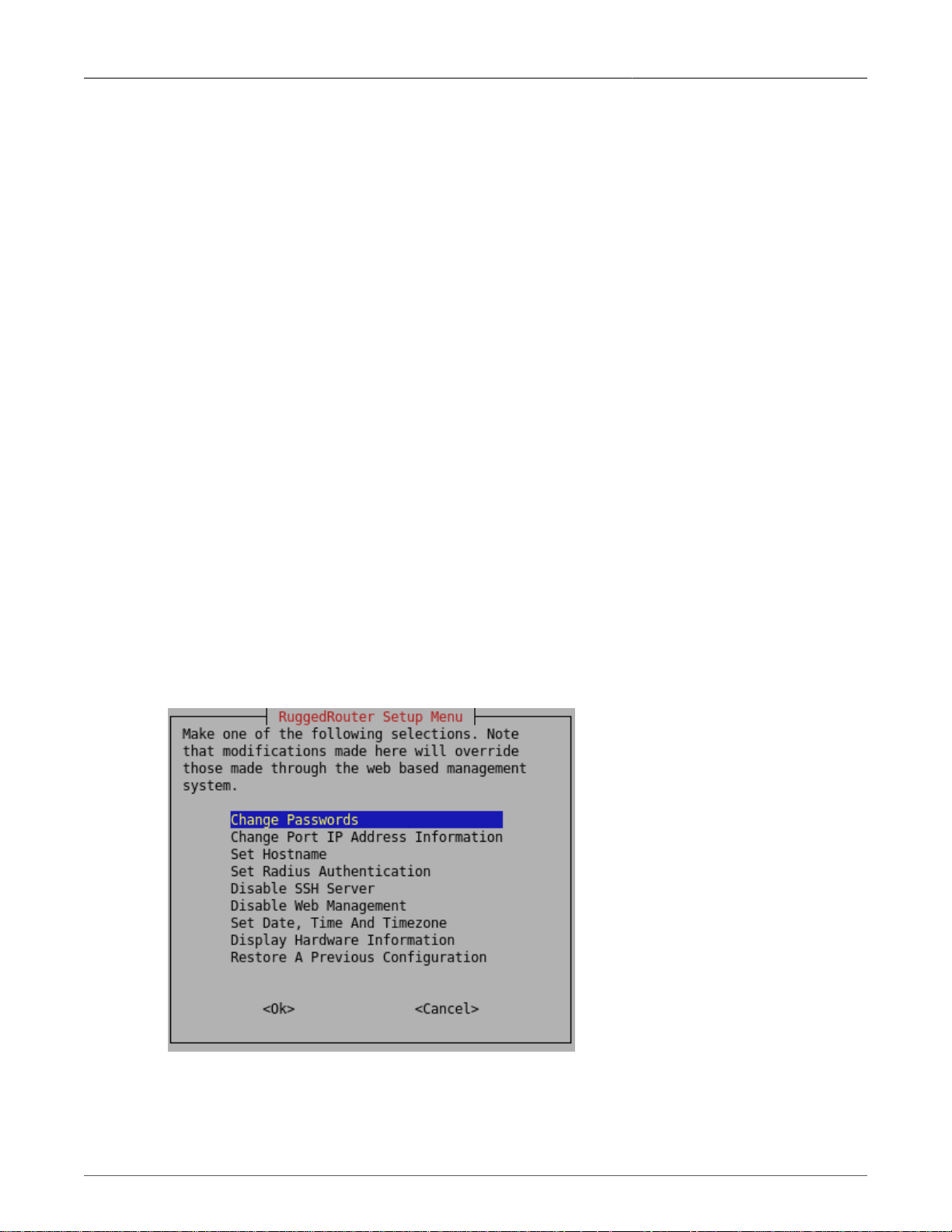
1. Setting Up And Administering The Router
• Superuser account "root", password "admin",
• SSH and Web Management interfaces are enabled by default. All other services (including
Serial Protocol Server, DHCP server, NTP server, End to End Backup Server, VPN Server,
NFS, OSPF/RIP protocol and firewall) are disabled by default.
1.2. Accessing The RuggedRouter Command Prompt
1.2.1. From the Console Port
Attach a terminal (or PC running terminal emulation software) to the RS232 port on the rear of the
chassis. The terminal should be configured for 8 bits, no parity operation at 38.4 Kbps. Hardware and
software flow control must be disabled. Select a terminal type of VT100.
Once the terminal is connected, pressing <CR> will prompt for the user to login as and that user's
password. Sign-in as either the rrsetup or root user. The router is shipped with default passwords of
"admin" for either of these accounts.
1.2.2. From SSH
Use an SSH agent running the version 2 protocol. SSH to either the rrsetup or root accounts of the
router at one of its IP addresses described above. The router is shipped with default passwords of
"admin" for either of these accounts.
1.3. The RuggedRouter Setup Shell
Signing-in as the rrsetup user will automatically enter the configuration shell shown below. Quitting
the shell (with cancel, or by entering escape) will cause the connection to close.
Figure 1.1. RuggedRouter Setup Main Menu
The shell provides a number of configuration commands, described below.
Revision 1.14.3 24 RX1000/RX1100™
Page 25
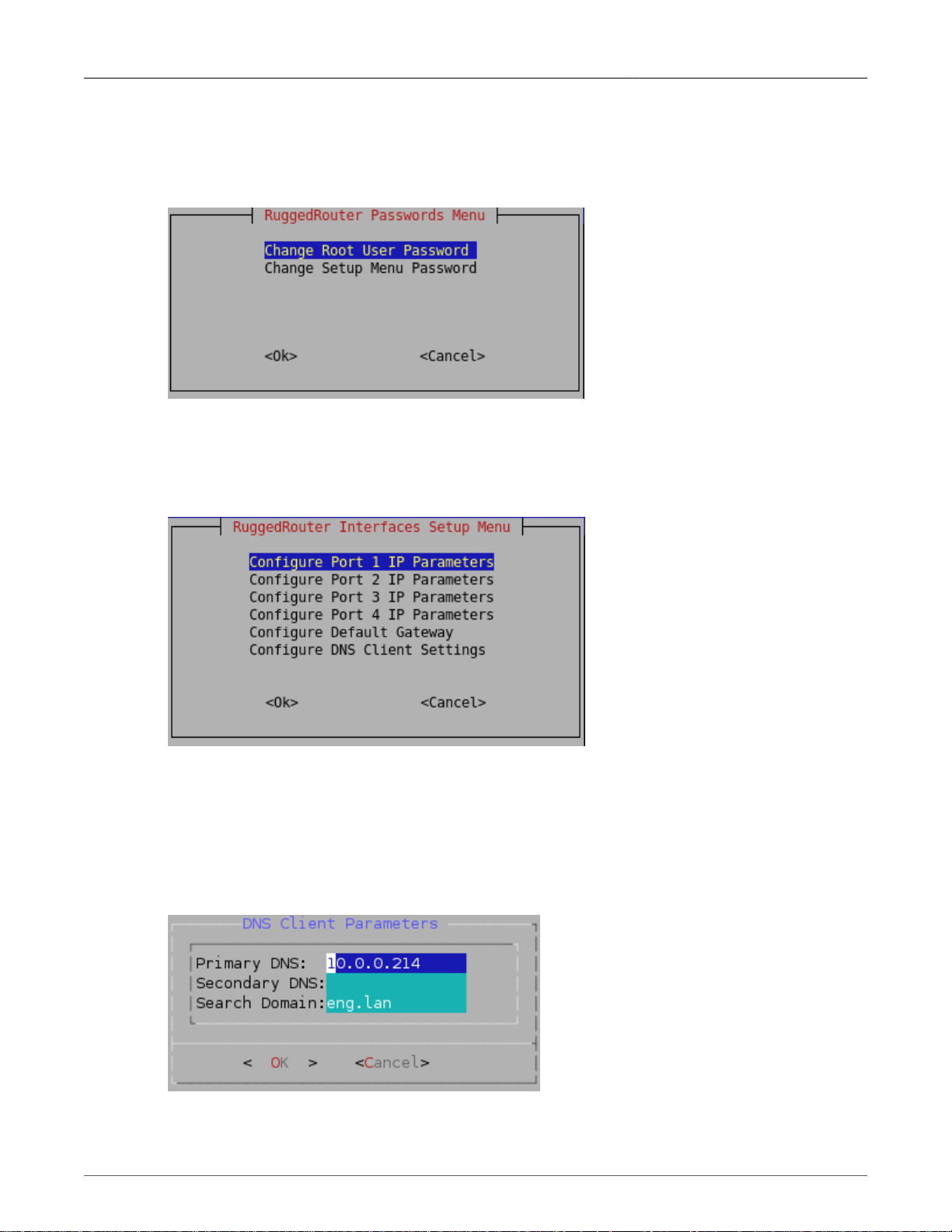
1. Setting Up And Administering The Router
1.3.1. Configuring Passwords
The Change Passwords command changes the rrsetup and root account passwords. These
passwords should be changed before installing the router on the network.
Figure 1.2. RuggedRouter Setup Password Change Menu
1.3.2. Configuring IP Address Information
The Change Port IP Address command configures port IP addresses and gateways.
Figure 1.3. RuggedRouter Interfaces Setup Menu
Each port number X has a default address of 192.168.X.1 and a mask of 255.255.255.0.
The Configure Default Gateway Settings command configures the default gateway.
The Configure DNS Client Settings command configures the DNS server address. If the router is
part of a domain, enter the domain name in the Search Domain field.
Figure 1.4. RuggedRouter DNS Client Menu
Revision 1.14.3 25 RX1000/RX1100™
Page 26
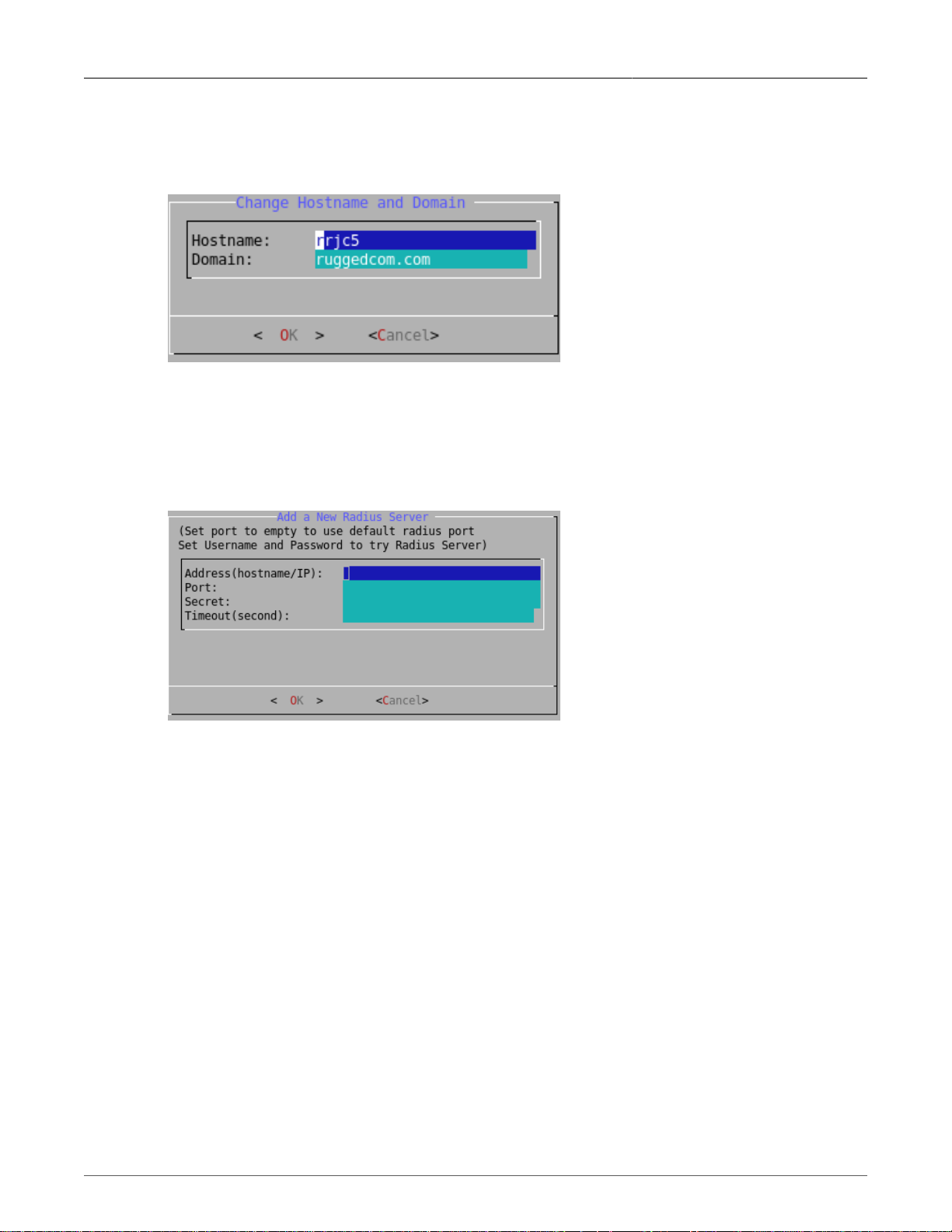
1. Setting Up And Administering The Router
1.3.3. Setting The Hostname and Domain
The Set Hostname command sets the hostname and the domain.
Figure 1.5. Hostname and Domain Configuration Menu
1.3.4. Configuring RADIUS Authentication
The Set RADIUS Authentication command configures the address of a RADIUS server, if one is
available.
Figure 1.6. RADIUS Server Configuration menu
The Hostname/IP field configures the RADIUS server's IP address.
The Port Number field sets the port number used by the RADIUS server. The default port for RADIUS
is 1812.
The Shared Secret field configures a unique password used to authenticate communications with
this server. Note that the shared secret must also be configured on the RADIUS server for the router
being configured.
The Timeout field sets the maximum time in seconds to wait for responses from the RADIUS server
before aborting a transaction.
The entry, created for both LOGIN and PPP Login, can be changed from the web interface.
1.3.5. Enabling And Disabling The SSH and Web Server
By default SSH and Web Management are enabled. The Disable SSH and Disable Web
Management commands allows these services to be disabled. The servers will be immediately
Revision 1.14.3 26 RX1000/RX1100™
Page 27
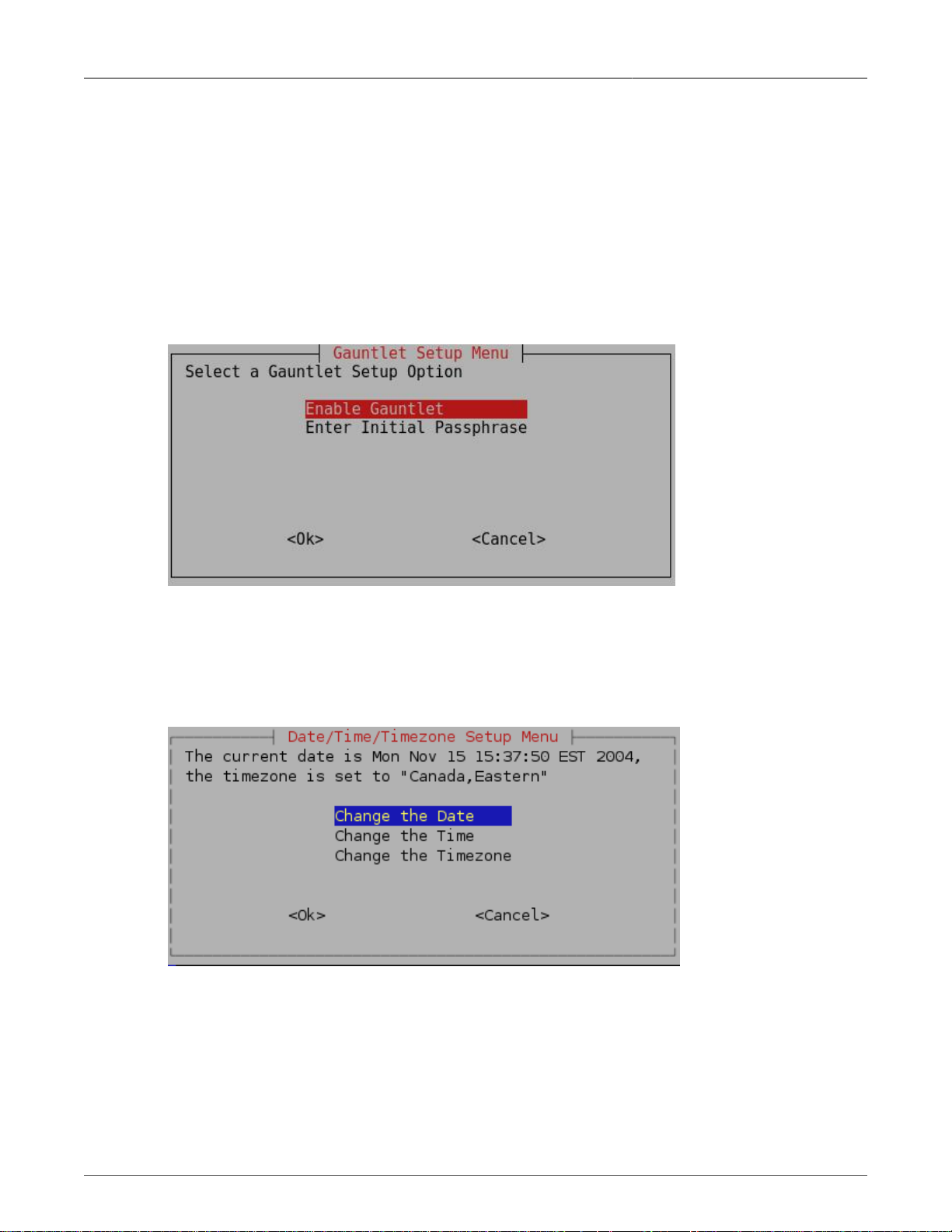
1. Setting Up And Administering The Router
stopped. If access to the shell has been made through ssh the session will continue, but no new
sessions will be allowed.
Upon disabling the services, the titles in the main menu will change to Enable SSH and Enable Web
Management to reflect the disabled state. Enabling a service automatically restarts it.
1.3.6. Enabling And Disabling The Gauntlet Security Appliance
The Gauntlet security Appliance requires a pass phrase unique to your network. This menu will
configure it.
Figure 1.7. Gauntlet Setup Menu
1.3.7. Configuring The Date, Time And Timezone
The Set The Date, Time And Timezone command allows these parameters to be set.
Figure 1.8. RuggedRouter Date/Time/Timezone Menu
Once set, the router will account for Daylight Savings time.
1.3.8. Displaying Hardware Information
The Display Hardware Information command describes commissioned hardware.
Revision 1.14.3 27 RX1000/RX1100™
Page 28
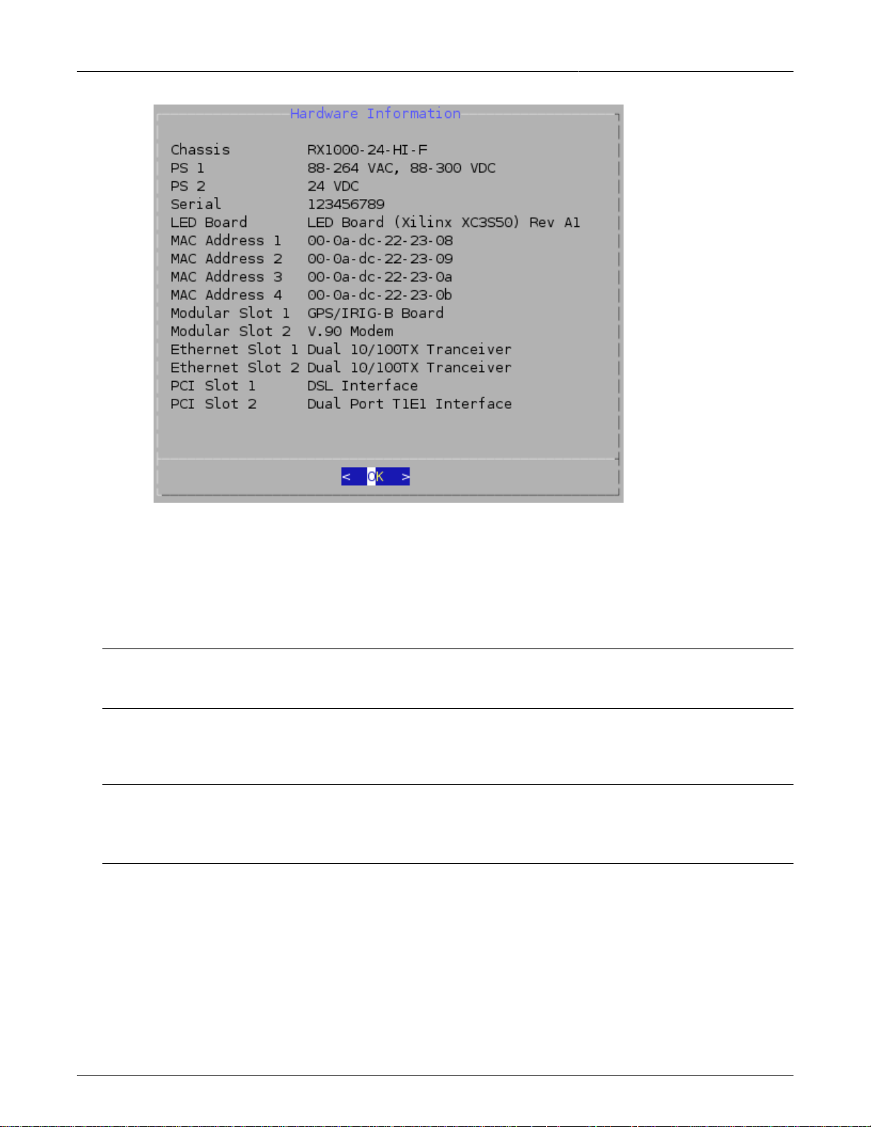
1. Setting Up And Administering The Router
Figure 1.9. RuggedRouter Hardware Information Menu
1.3.9. Restoring A Configuration
The Restore A Previous Configuration command provides a means to restore a previously taken
snapshot of the configuration of the router.
Note
The router will reboot immediately after restoring configuration.
The user is first prompted to select either the factory default configuration or a previously made
archive.
Note
Restoring the factory defaults will reset IP addresses and may make the router impossible to reach
from the network.
Revision 1.14.3 28 RX1000/RX1100™
Page 29
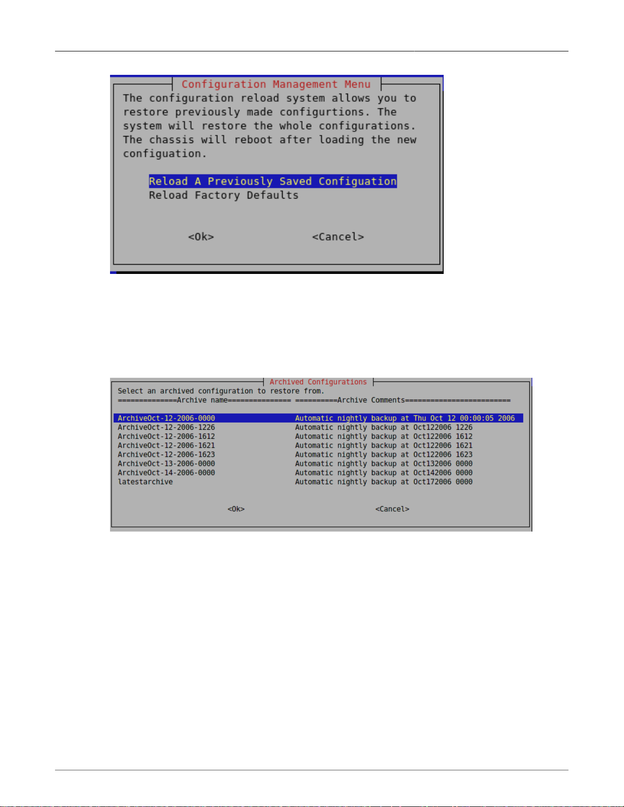
1. Setting Up And Administering The Router
Figure 1.10. Selecting a configuration to reload
Initially, your RuggedRouter will have no previously saved configurations. The factory defaults will
always be available.
Once a configuration is selected the archive will be restored. After the configuration is restored, the
router will reboot immediately.
Figure 1.11. Selecting a previously made configuration
1.4. The RuggedRouter Web Interface
The RuggedCom Web interface is provided by an enhanced version of the popular Webmin interface.
1.4.1. Using a Web Browser to Access the Web Interface
Start a web browser session and open a connection to the router by entering a URL that specifies its
hostname or IP address (e.g. h ttps://179.1.0.45:10000). Once the router is contacted, start the login
process by clicking on the Login link. The resulting page should be similar to that presented below.
Enter the "root" user name and the appropriate password for that user, then click on the Login button.
The router is shipped with a default administrator password of "admin". Once successfully logged in,
the user will be presented with the main menu.
Revision 1.14.3 29 RX1000/RX1100™
Page 30

1. Setting Up And Administering The Router
Figure 1.12. Signing On To The Router With A Web Browser
1.4.2. SSL Certificate Warnings
Your browser may complain about the SSL certificate that Webmin issues.
This happens because the default SSL certificate that comes with Webmin is not issued by a
recognized certificate authority. From a security point of view, this makes the certificate less secure
because an attacker could theoretically redirect traffic from your server to another machine without
you knowing, which is normally impossible if using a proper SSL certificate.
Network traffic is still encrypted though, so you are safe against attackers who are just listening in
on your network connection.
If you are initiating the connection to the router, and your network is private, a VPN or firewalled, it
should be safe to have your browser permanently accept the certificate.
If you want to be really sure that the Webmin server you are connecting to is really your own, the only
solution is to order a certificate from an authority like Verisign that is associated with your router's
hostname and will be recognized by web browsers.
1.4.3. The Structure of the Web Interface
The Web interface presents an web page with two frames. The leftmost or index frame selects
subsystems to configure and is always displayed.
The rightmost or configuration frame presents the configuration for the currently selected subsystem,
or in the case of signing-on, the home page window. The home page window presents an annotated
view of the front of the chassis as well as a number of important system parameters. These parameters
include:
• The router uptime and load averages for the past 1, 5 and 15 minutes. Under normal operation
the load average should be less than 2.0.
• The disk usage. A disk usage higher than 92% requires attention.
• The memory usage, indicating the amount of memory used by applications. Under normal
operation memory usage should be less than 60%.
• The chassis temperature.
• Any major alarms, such as the failure of hardware components.
Revision 1.14.3 30 RX1000/RX1100™
Page 31

1. Setting Up And Administering The Router
Figure 1.13. RuggedRouter Web Interface Main Menu Window
The index frame presents a number of entries with associated icons:
•
The icon causes home page window to be redisplayed.
•
The icon signifies that the next level contains a menu of menus.
•
The icon signifies that clicking the entry will run a single menu.
•
The icon logs out of Webmin.
The menu system entries are composed of the Webmin, System, Servers, Networking and
Maintenance menus.
The Webmin Menu provides the ability to:
• Configure the sign-on password,
• Specify session timeouts,
• Restrict the Subnet of IP addresses that can login,
• Configure and view Webmin event logs,
Revision 1.14.3 31 RX1000/RX1100™
Page 32

1. Setting Up And Administering The Router
The System Menu provides the ability to:
• Change the router password,
• Enable and disable applications from running,
• Reboot the router,
• Schedule one time and periodic tasks to run,
• Change the router's name (hostname),
• Change the time and date.
The Servers Menu provides the ability to:
• Control and configure the Serial Protocol, DHCP, NTP, IRIGB and SSH servers.
The Networking Menu provides the ability to:
• Configure the network interfaces,
• Configure static IP and Multicast Routings and configure a default gateway,
• Select a DNS server and edit local host addresses,
• Configure End To End Backup,
• Configure DDS, T1/E1, T3 and ADSL Networking,
• Configure the embedded modem,
• Set up the firewall,
• Set up Virtual Private Networking,
• Configure Routing protocols such as OSPF and RIP,
• Configure Virtual Router Redundancy Protocol (VRRP),
• Configure Traffic Prioritization,
• Perform pings, traceroutes, host lookups and line tracing.
The Maintenance Menu provides the ability to:
• Manage the Gauntlet Security Appliance
• Backup and restore configurations,
• Configure SNMP access,
• Configure RADIUS Authentication,
• View system logs,
• Upgrade the software of the router,
• Upgrade the router type to RX1100,
• Upload/Download files to and from the router.
1.5. Using The LED Status Panel
The LED status Panel provides the console port, indicates the status of hardware/software and can
initiate a controlled reboot.
Revision 1.14.3 32 RX1000/RX1100™
Page 33

1. Setting Up And Administering The Router
Figure 1.14. LED Status Panel
The LEDs are organized into three primary groups; the port group, GPS/PPP group and the Alarm/
Power Supply group. The display possibilities are as follows:
LED Name Description
LED 1-4 Green: link activity on Ethernet port 1-4
LED 5-8 Green: link detected on Ethernet port 1-4
Red: link failure on Ethernet port 1-4
LED 9-12 Green: link activity on WAN port 1-4
LED 13-16 Green: link detected on WAN port 1-4
Red: link failure on WAN port 1-4
LED 17-20 Green: link activity on WAN port 5-8
LED 21-24 Green: link detected on WAN port 5-8
Red: link failure on WAN port 5-8
PPP-DATA Green: link activity on PPP Modem port
PPP-LINK green: link detected on PPP Modem port
GPS-LOCK Green: The PTP card has acquired a GPS satellite lock
ALARM Red: A Major Alarm exists
POWER 1 Green: Power Supply 1 is working properly
Red: failure detected in Power Supply 1
POWER 2 Green: Power Supply 2 is working properly
Red: failure detected in Power Supply 2
Table 1.1. Meaning of LEDs
The software will cause the ALARM LED to become active for various reasons. Any condition that
causes the ALARM LED to become active will activate the critical fail relay. The Web interface displays
the alarms.
Pressing the pushbutton for more than five seconds will reboot the router.
1.6. Obtaining Chassis Information
The chassis displays the hardware inventory at boot time. This information is captured in the /var/
log/messages file after boot. The Web Management interface home page displays the chassis serial
number.
Revision 1.14.3 33 RX1000/RX1100™
Page 34

2. Webmin Configuration
2. Webmin Configuration
2.1. Introduction
This chapter familiarizes the user with configuring the router through the Webmin menu and describes
the following procedures:
• Configuring the IP Address and Subnet Mask
• Configuring the Gateway Address
• Viewing the Webmin Log
2.2. Webmin Configuration Menu
Figure 2.1. Webmin Configuration Menu
2.2.1. IP Access Control
Figure 2.2. Webmin Configuration Menu, IP Access Control
Webmin uses a secure communications method called Secure Sockets Layer (SSL) to encrypt traffic
with its clients. Webmin guarantees that communications with the client is kept private. But Webmin
will provide access to any client that provides the correct password, rendering it vulnerable to brute
Revision 1.14.3 34 RX1000/RX1100™
Page 35

2. Webmin Configuration
force attacks. The best way of addressing this problem is to restrict access to specific IP addresses
or subnets.
By default, IP access control allows all IP addresses to access Webmin.
If your router is being used on a completely private network, or IP access control is being provided
by the firewall you may leave IP Access Control disabled. Select the Allow from all addresses field
and Save.
If you wish to restrict access to a single address or subnet, select the Only allow from listed
addresses field. Enter a single IP address or a subnetted address.
If you wish to deny access to a specific subnet, select the Deny from listed addresses field. Enter
a single IP address or a subnetted address.
If DNS is configured you may allow and deny based upon hostname. Partially qualified domain names
such as *.foo.com are acceptable.
The Resolve hostnames on every request field forces Webmin to perform a hostname lookup for
every user access. The result of this will be that a dynamically assigned IP with a DNS entry with a
Dynamic DNS registrar will be able to be checked against the IP Access Control list, just like a fixed
address. This method is useful for administrators who travel or simply don't have a fixed address at
their normal location.
Note
This is not efficient if you have more than a few domain names entered in the IP Access Control
list, due to the high overhead of performing a name lookup for every hostname in the list on every
request.
2.2.1.1. Ports And Addresses
Figure 2.3. Webmin Configuration Menu, Ports and Addresses
This command allows you to restrict access to Webmin from one particular network interface on your
server. If your Webmin server has a non-routable local address and a routable Internet address, you
should decide whether anyone will ever need to be able to access the Webmin server from outside
of your local network. If not, simply configure Webmin to listen on the local interface.
By default, Webmin listens on TCP port 10000 for clients. It is possible to change this default
behaviour.
Revision 1.14.3 35 RX1000/RX1100™
Page 36

2. Webmin Configuration
2.2.2. Change Help Server
Figure 2.4. Webmin Configuration Menu, Change Help Server
The Web management package provides context sensitive help in each of its menus. When a help
link is selected the router instructs the browser to open the help text from a help server. In this way the
router does not waste large amounts of disk space storing help text and network bandwidth sending
large web pages. By default, the router directs the browser to the same server used to upgrade the
router. This is as specified in the Maintenance menu Upgrade System sub-menu Change Repository
Server command.
This command allows you to disable Web management help, use the upgrade repository server as
well as specify a new server. If you specify an alternate web server to host the help text, you must
install release specific help directories below the document root. The menu suggests the currently
expected directory. The actual help files are provided with every release under the html directory at
the repository server.
2.2.3. Logging
Figure 2.5. Webmin Configuration Menu, Logging
Revision 1.14.3 36 RX1000/RX1100™
Page 37

2. Webmin Configuration
This menu allows you to log actions taken by Webmin administrators.
It is also possible to log actions based on the module where the actions are performed.
The Log resolved hostnames field will cause Webmin to provide a hostname rather than just an IP
address for the client computer that performed an action.
The Clear logfiles every...hours field causes Webmin to rotate its own logs and keep them from
overfilling the disk with old logs.
Currently, the Log actions by all users field should be left selected.
The Log changes made to files by each action field causes verbose logging and should be left
enabled.
2.2.4. Authentication
Figure 2.6. Webmin Configuration Menu, Authentication
This menu allows you to configure what Webmin will do when a number of failed logins from the same
IP address occur.
If the Enable password timeouts field is selected, the host will be blocked for the specified period
of time. If the Log blocked hosts, logins and authentication failures to syslog field is selected,
warning messages will be added to the syslog.
Enabling the Enable session authentication field, activating “Auto-logout after..” will cause an
individual administrators session to be logged out after the specified period.
Revision 1.14.3 37 RX1000/RX1100™
Page 38

2. Webmin Configuration
2.2.5. Webmin Events Log
Figure 2.7. Webmin Events Log
This menu allows you to search the Webmin log for changes made by yourself or other administrators.
Revision 1.14.3 38 RX1000/RX1100™
Page 39

3. Configure Webmin Users
3. Configure Webmin Users
3.1. Introduction
This chapter familiarizes the user with:
• Configuring Webmin users
• Displaying and removing existing login sessions
• Setting up password restrictions
3.2. Webmin User and Group Fundamentals
When the Webmin package is installed for the first time, an account for the user: "root" exists on the
router. Besides the root account, three groups, or privilege levels, are defined: "admin", "operator",
and "guest".
• Users belonging to the "admin" group have full access to all Webmin modules.
• Users belonging to the "operator" group have full access to most Webmin modules with the
following exceptions:
• Webmin Configuration
• Webmin Event Log
• Webmin Users
• Scheduled Commands
• Scheduled Cron Jobs
• System Hostname
• System Time
• SSH Server
• Backup And Restore
• Upgrade System
• Upload/Download Files
• Users belonging to the "guest" group can only view configuration and statistics but can not
change them. Besides this limitation, they also have no access to the modules forbidden to the
"operator" group, listed above.
The "root" user must always be defined. New Webmin users can be created and deleted, and must
belong to one of the three aforementioned groups. New Webmin user names must contain only the
characters "a-zA-Z0-9-.@" but must not begin with "@" and must not conflict with any existing user
or group name.
3.3. RADIUS User Access Control Fundamentals
Webmin provides the ability to authenticate against a RADIUS server in order to centralize the creation
and maintenance of user accounts. Multiple RuggedRouters may be configured to authenticate
Revision 1.14.3 39 RX1000/RX1100™
Page 40

3. Configure Webmin Users
Webmin users using a common RADIUS server, eliminating the need to replicate the effort of
configuring the same user account information on many routers.
If RuggedRouter is configured to use RADIUS to authenticate Webmin users (in the Miscellaneous
module under the Maintenance category), the router will present the configured RADIUS server with
the user name and password presented to a Webmin session for authentication. If the RADIUS server
authenticates the user, it will return an indication of success along with the privilege level (described
above) associated with the user.
A user successfully authenticated by a RADIUS server will have Webmin access corresponding to
his/her privilege level, as configured for the user account on the RADIUS server. For information on
how to configure user accounts on a RADIUS server, please refer to RADIUS Server Configuration.
Note
A Webmin user will only be authenticated locally if a user account of that name has already been
created in Webmin.
Note
The Change Password Command can only be accessed via a locally defined user account.
3.4. Webmin Users Menu
Figure 3.1. Webmin users menu
This menu allows you to create, change or delete a Webmin user, to view and remove current login
sessions, and to set password restrictions.
Click the Select all link to select all manually created users.
Click the Invert selection link to deselect all manually created users.
Click the Create a new Webmin user link to create a new Webmin user.
Revision 1.14.3 40 RX1000/RX1100™
Page 41

3. Configure Webmin Users
Click on manually created user name to change its setting.
Click the Delete Selected button to delete selected users.
Click the View login sessions button to view all current login sessions.
Click the Password Restrictions button to set the password restriction rules.
Note
The accounts managed from this menu are local to the RuggedRouter, and are not maintained
on a RADIUS server, even if one is configured.
3.5. Edit Webmin User menu
This menu allows you to change the user name, group membership, password, and real name for
a user account.
Figure 3.2. Edit Webmin User Menu
The Username field sets the user name for the Webmin user. This user name will be used in the login.
The Member of group field determines which group the user belongs to. Recall that the group is
equivalent to the privilege level, which determines the user's access level for the Webmin system.
The Password field sets the password for the user.
The Real name field sets the real name for the user.
The Save button will save the changes permanently.
The View Logs button will display the action logs for this Webmin user.
The Delete button will delete the current user from Webmin.
Note
When a Webmin user is deleted, any current session the user may have established will be
terminated.
Revision 1.14.3 41 RX1000/RX1100™
Page 42

3. Configure Webmin Users
3.6. Current Login Sessions Menu
Figure 3.3. Current login sessions menu
This menu allows you to view and delete current login sessions (delete login session will force the
login user to login again).
Click on Session link under the Session ID column to cancel a session.
Click the Webmin user link under the Webmin user column to display the Webmin user edit menu
for that user.
Click the View logs link to display logs for that Webmin user.
3.7. Password Restrictions Menu
Figure 3.4. Password Restrictions Menu
This menu allows you to set restrictions for password selection in order to prevent the use of trivial,
or machine-guessable passwords.
The Minimum password length field sets the minimum length for password.
The Regular expression passwords must match field sets the regular expression that a new
password must match. The above example restricts new passwords to begin with an alpha character
followed by at least another 5 alphanumeric characters.
The Disallow passwords containing username field prevents new passwords from containing the
user name.
The Number of old passwords to reject field determines after how many successful passwords
settings you are allowed to reuse an old password.
Revision 1.14.3 42 RX1000/RX1100™
Page 43

3. Configure Webmin Users
A Note on Regular Expressions
The Password restriction mechanism in ROX uses PERL regular expression syntax. For the
definitive reference documentation on regular expressions in PERL, please refer to:
• http://perldoc.perl.org/perlreref.html
• http://perldoc.perl.org/perlre.html
• http://perldoc.perl.org/perlretut.html
• http://perldoc.perl.org/perlrequick.html
If you do not have access to an Internet connection, but do have a UNIX / Linux system with PERL
installed, access the local manual pages by typing:
• man perlreref
• man perlre
• man perlretut
• man perlrequick
at the command line. Root privilege is not required to access manual pages.
Revision 1.14.3 43 RX1000/RX1100™
Page 44

4. Configuring The System
4. Configuring The System
4.1. Introduction
This chapter familiarizes the user with:
• Enabling and disabling processes such as SSH and Web Management
• Changing the system password
• Shutting down and rebooting the system
• Scheduling one-off and periodic commands
• Examining system logs
• Changing the hostname
• Changing the system time and timezone
Revision 1.14.3 44 RX1000/RX1100™
Page 45

4. Configuring The System
4.2. Bootup And Shutdown
Figure 4.1. Bootup and Shutdown, Part 1
This menu allows you to enable/disable services and to perform actions at boot. The first part of the
menu manages services. Check the box for the desired service and click on Start Selected to start
the service and have it start at the next boot. Click on Stop Selected to stop the service and not
have it start at boot.
The Reboot System button will cause the system to reboot.
The Shutdown System button shuts down the system in order to remove power.
Revision 1.14.3 45 RX1000/RX1100™
Page 46

4. Configuring The System
Note
The RuggedRouter never enters a permanent shutdown state. If the RuggedRouter is instructed
to shutdown, either from Webmin or from a shell command, it will reboot into a command line shell
that waits five minutes before restarting.
If you really want the router to remain powered but permanently inactive, you must issue the shutdown,
connect a terminal to the serial port, wait for the router to enter the shutdown shell and issue a CTRL-C.
The second part of the menu allows you to program specific actions at boot time. The script will be
run after all regular boot actions have completed.
Figure 4.2. Bootup and Shutdown, Part 2
The actions may be a series of commands that can be executed at the command line. Each entered
line is executed independently of the previous line, so change directory commands will not be effective.
Always specify the absolute path of files used in commands. Selecting Save And Run Now will run
the script and show its output, allowing you to debug it.
4.3. Change Password Command
Figure 4.3. System Menu Change Password Command
This command changes only the root account password used to login to Webmin and the root account
via the serial console or SSH.
Revision 1.14.3 46 RX1000/RX1100™
Page 47

4. Configuring The System
4.4. Scheduled Commands
Figure 4.4. Scheduled Commands
This menu allows you to schedule a command to run in the future.
Begin by selecting the time and date you wish to run the command at using the Run on date and
Run at time fields.
Use the Run in directory field to enter a directory to run the command in, or simply use “/”.
Finally, enter the command to execute in the Commands to execute field.
Note that the command will remain scheduled after reboot. After the command is entered, the
Scheduled Commands menu will display any commands and allow you cancel them.
Figure 4.5. Scheduled Commands Displaying a Command
4.5. Scheduled Cron Jobs
"Cron" is a service that allows flexible, regular scheduling of system commands. A "Cron job" is the
set of a command to run and a definition of the times at which to run it. The Scheduled Cron Jobs
menu allows you to create, edit, and delete these jobs.
Figure 4.6. Webmin Scheduled Cron Jobs
Revision 1.14.3 47 RX1000/RX1100™
Page 48

4. Configuring The System
Initially, there will be no scheduled jobs. Follow the create link to create one.
Figure 4.7. Creating a Cron Job
Begin the creation of a cron job specification by selecting a user to execute as. For most purposes,
"root" will suffice. Enter the user name in the Execute cron job as field.
Enter the command to execute and any input to the command in the Command field. Select the times
the script is to run from the When to execute table (remember to check the selected button above
any column you edit).
The Active radio button at the top of the menu temporarily disables the job.
After selecting the Create button, the Scheduled Cron Jobs menu will display the job.
Figure 4.8. Scheduled Cron Jobs menu displaying cron jobs
Follow the link of a specific job in order to delete the job, edit it, or test the command part of the job
by running it immediately.
Revision 1.14.3 48 RX1000/RX1100™
Page 49

4. Configuring The System
If you have multiple jobs, the arrows in the Move column will alter the order in which they are
presented.
4.6. System Hostname
Figure 4.9. System Hostname
The Hostname field modifies the hostname as presented in the web server and shell sessions.
The Domain field modifies the domain as presented in the web server and shell sessions. The default
is "localdomain".
Note that the new hostname and domain settings will only appear in new sessions.
4.7. System Time
Figure 4.10. System Time
This menu provides a method to set the router's time and timezone.
Note
OSPF and RIP are sensitive to accurate system time. If OSPF or RIP are enabled, changing the
time from this menu will cause them to be restarted.
Revision 1.14.3 49 RX1000/RX1100™
Page 50

5. Configuring Networking
5. Configuring Networking
5.1. Introduction
This chapter familiarizes the user with:
• Configuring routing and gateways
• Configuring DNS (Dynamic Name Service)
• Entering host addresses
• Configuring a pair of End To End Backup interfaces
• Viewing routing tables
5.2. IPv6 Fundamentals
Version 6 of the Internet Protocol (IPv6, RFC 2460) has been designated to replace IPv4 throughout
the Internet. Some important changes that IPv6 introduces relative to IPv4 fall into the following
categories:
• Addressing
IPv6 addresses are four times the length of IPv4 addresses, at 128 bits, to be used as 64 bits
of network and 64 bits of host address. The larger address space allows much greater flexibility
in hierarchical network definition and routing.
• Header Format
The IPv6 packet header has been simplified relative to IPv4 in order to simplify and therefore
speed the processing of packets by routing nodes. It also features more efficiently encoded
options and greater flexibility in creating extensions.
• Security
Security has been designed into IPv6, rather than being treated as a component that must be
added to existing IPv4 network stacks.
5.3. Network Configuration
Figure 5.1. Network Configuration Menu
This menu allows you to configure IP networking parameters.
Revision 1.14.3 50 RX1000/RX1100™
Page 51

5. Configuring Networking
Select the Core Settings icon to configure kernel networking settings such as syncookies filtering.
Select the Dummy Interface in order to assign an IP Address to the router that is independent of
its interfaces.
Select the Routing and Default Route icon to assign a gateway address.
Select the Static Multicast Routing icon to configure static multicast routes.
Select the DNS Client icon to point the router at a DNS server.
Select the Host Addresses icon to locally configure IP address-hostname mappings.
Select the End To End Backup icon to configure an end to end backup connection.
Select the Current Routing & Interface Table icon to view the routing table.
The Apply Configuration button serves to restore the permanently saved changes and restart
Ethernet networking.
5.3.1. Core Settings
Figure 5.2. Core Networking Settings
This menu allows you to configure core networking settings.
The Allow IPv6 Configuration field determines whether IPv6 may be configured via Webmin.
The Ignore All ICMP ECHO field corresponds to the kernel icmp_echo_ignore_all setting. Setting
Ignore All ICMP ECHO to "yes" will cause the kernel to reject incoming ICMP ECHO request packets.
The Ignore ICMP Broadcasts field corresponds to the kernel icmp_echo_ignore_broadcasts setting.
Setting Ignore ICMP Broadcasts to "yes" will cause the kernel to reject incoming ICMP ECHO request
packets if their destination address is a broadcast address.
The Syncookie Protection field corresponds to the kernel tcp_syncookie setting. Setting Syncookie
Protection to "yes" will cause the kernel to protect against SYN flood attacks.
The Send ICMP Redirect field corresponds to the kernel send_redirect setting. Consider a networked
host H1 sending an IP datagram to a remote host H2. H1 is on the same network segment as two
routers: R1 and R2. If host H2 is reachable via R2, and H1 sends an IP datagram to H2 via R1, then
Revision 1.14.3 51 RX1000/RX1100™
Page 52

5. Configuring Networking
assuming that R1 has a route to H2 via R2, R1 will send an ICMP redirection message to H1 informing
it that the route to H2 is via R2. Setting Send ICMP Redirect to "no" will cause the kernel not to send
an ICMP redirect message even if one would normally be sent.
5.3.2. Dummy Interface
Figure 5.3. Dummy Interface
This menu allows you to configure a dummy interface. Normally the router is reachable on any of its
interface addresses, whether the interface is active or not. When OSPF and link detection is used,
inactive interfaces are not advertised to the network and thus not reachable. A dummy interface is
always advertised and is thus reachable. Pressing the Save button will save the configuration change.
Pressing the Delete button will remove the dummy interface.
5.3.3. Static Routes
This menu allows you to configure static routing entries, including default routes. Each static route
specifies how the router can reach a remote subnet. It also allows the conversion of other static routes,
obtained via DHCP for example, to permanently configured static routes.
If IPv6 support is enabled in the Core settings menu, IPv6 static routes may also be configured here.
If multiple gateways are availabe to route to a given remote subnet, a static route entry may be entered
for each one, with the same subnet and different gateway specifications. Typically, one would also
enter a different metric for each route, the lowest metric indicating the preferred route.
Multipath Routes
It is also possible to specify the same metric for each one of several alternative routes to the same
remote subnet. This allows the creation of a multipath route. With such a set of redundant routes
available to a remote subnet, the router will select one or another route to transmit traffic destined
to the subnet.
The end result is that the aggregate of data traffic to the remote subnet is shared among the multiple
routes. Note the distinction between Multipath Routing and Multilink PPP: whereas Multilink PPP
effectively multiplies the bandwidth for all traffic by the number of links that comprise a 'bundle',
Multipath Routing multiplies the capacity of the route, at link-native speeds, by the number of different
routes provided.
Default Routes
A default route is a special instance of a static route. The destination network of 0.0.0.0/0 is the
most general possible IPv4 network specification. Packets destined to an IPv4 subnet that is not
Revision 1.14.3 52 RX1000/RX1100™
Page 53

5. Configuring Networking
reachable via any other routing entry in the system will be forwarded to the default gateway, i.e., the
gateway for the default route. Default routes for both IPv4 and IPv6 may be configured.
5.3.3.1. Configuring Static Routes
Figure 5.4. Static Routes
Note
Modem PPP, PPPoE on ADSL, and any interface configured to obtain IP configuration via DHCP
may also negotiate default gateways independently of this configuration menu.
The Network/Mask field specifies the remote subnet field of a static route definition. If this field is
cleared, the route will be deleted when Save is clicked. The Network is specified in dotted quad
notation, and the Mask (the number of bits in the subnet mask) is an integer between 0 (for a default
route) and 32 (for a host route).
Note
It is possible to create a route on a locally connected broadcast network (i.e. without a gateway)
without also bringing up a corresponding IP address on that interface. For example, it would
be possible to add 192.168.30.0/24 to eth1, which has an IP address of 10.0.1.1 but no
corresponding alias address on the 192.168.30.0/24 subnet.
The Gateway field specifies the IP address of the 'next hop' to which to forward traffic destined to the
specified subnet. If the gateway to a particular subnet is across a point-to-point link, it is not necessary
to specify a gateway, but a network interface (below) must be specified.
The Interface field specifies the network interface to use to reach the gateway. The interface does
not need to be active or even exist, but the route will not be installed until both are true. Specifying
an interface is only strictly necessary when a gateway address is not specified. The menu provides
a list of currently configured interfaces for quick reference.
Revision 1.14.3 53 RX1000/RX1100™
Page 54

5. Configuring Networking
Note
A "blackhole", or "null" route may be installed by entering "null0" in the interface field.
The Metric field specifies an integer cost metric for the route, which is used when choosing among
multiple routes in the routing table that most closely match the destination address of a packet being
forwarded. The route with the lowest metric is chosen as the active route.
Note
Multiple routes to the same destination subnet may also be specified using identical metrics in
order to create multipath routes. Please refer to Multipath.
The Comment field shows the status of the static route, and provides a basic cause when the route
is not installable.
The Save button below the table will perform the following sanity checks on routing entries that have
been added or modified. If the tests pass, the routes will be saved and immediately installed.
• A specified Gateway must be reachable, and if a network interface is also specified, must be
reachable via that interface.
• If a specified network interface exists but is not active, the static route will be installed and
marked, "Inactive (interface is not active)".
• If a specified network interface does not exist (e.g. an on-demand modem PPP connection) the
static route will be installed and marked, "Inactive (interface does not exist)".
Delete routes by removing their Network/Mask addresses before saving.
Note
In order to redistribute static routes to other routers, the Redistribute Static option must be
enabled in the corresponding OSPF, RIP, or BGP configuration's Global parameters menu in
Webmin.
5.3.3.2. Other Static Routes
This table will be shown if there are active static routes which were not configured manually in the
Configured Static Routes table. The Save to Configured Static Routes link next to each route
entry in this table will make the corresponding route permanent.
Note
There are situations where manually entered routes should not be converted, e.g. routes
dynamically added by IPsec and GRE tunnels. Making these routes permanent may cause the
daemons that add them to fail.
Revision 1.14.3 54 RX1000/RX1100™
Page 55

5. Configuring Networking
5.3.4. Static Multicast Routing
Figure 5.5. Static Multicast Routing
This menu allows you to configure static multicast routing.
The Configured Static Multicast Routes table shows configured multicast routes.
New routings may be added by completing the bottom row of the table and selecting the Save button.
Routings may be deleted by clearing the routings Multicast IP Address field and selecting the Save
button.
The Multicast IP Address field specifies the multicast IP address to be forwarded.
The Input Interface field specifies the interface upon which the multicast packet arrives.
The Source IP Address specifies the multicast packet's expected source IP address.
The Output Interface specifies the interface to which the matched multicast packet will be forwarded.
The Comment field shows the current status of the routing.
The Note field below the table shows current active interfaces.
In order to start Multicast routing at each and every boot, you must enable it via the System folder,
Bootup And Shutdown menu.
5.3.5. DNS Client
Figure 5.6. DNS Client
Revision 1.14.3 55 RX1000/RX1100™
Page 56

5. Configuring Networking
This menu allows you to display and configure various DNS client fields.
The DNS servers fields allow you to specify, in order, the servers from which to request Internet
Domain Name resolution.
The Search domains field allow you to specify the domain names of, primarily, the domain of which
the router is a member, and secondarily, other domains that may be used to search for an unqualified
host name (i.e. as though it were local). If a domain name is not specified here, the router will attempt
to extract this information from the host addresses.
5.3.6. Host Addresses
Figure 5.7. Host Addresses
This menu allows you to display and configure host addresses. Host addresses are useful when a
non-changing IP address is often used or when DNS is not configured.
Follow the Add a new host address link to add an address.
5.3.7. End To End Backup
End To end backup is method of using two interfaces to ensure a reliable end to end connection
between two routers using alternate routing, without the need to configure routing protocols.
The two interfaces are assigned as a primary:secondary backup pair. The primary interface serves
as the gateway. If connectivity to the target is lost from the primary interface, traffic is migrated to the
secondary interface. When connectivity is restored on the primary path, traffic will be restored to it.
Revision 1.14.3 56 RX1000/RX1100™
Page 57

5. Configuring Networking
Figure 5.8. End To End Backup Example
The backup is “end to end” because connectivity is determined by the availability of an interface on the
target system, and not a local link. In the above figure, interface w1ppp acts as the primary interface
and eth1 acts as the secondary interface. The router tests the primary path by probing 192.168.16.2
on router 2. A failure of the either w1ppp, network A or the remote link on router2 will render the
primary path as “failed”.
If the primary path fails, the routing table will be modified to direct packets out the secondary (eth1
in the above figure).
Presumably, the secondary is a higher cost (and perhaps lower throughput) path. In the initial
deployment of this feature, the secondary path was implemented with Ethernet-CDMA modem. The
modem featured a low latency connection time (initiated by the reception of packets) but had a low
bandwidth capability and high monetary cost.
Note that the feature must be implemented at both routers. If the feature is only implemented at
router 1, the second router's gateway will still point towards Network A after a failure of the primary
path. Packets from router 1 would reach router 2 through the secondary, but the responses would
disappear in the black hole of the failed path.
Revision 1.14.3 57 RX1000/RX1100™
Page 58

5. Configuring Networking
5.3.7.1. Configuring End To End Backup
Figure 5.9. End To End Backup
This menu allows you to display and configure end to end backup.
In order to start end to end backup at each and every boot, you must enable it via the System folder,
Bootup And Shutdown menu. The menu will remind you if the feature is not enabled.
The Primary Interface field determines the primary interface. The interface selected should be
configured to supply the default gateway.
The Peer IP Address on Primary field sets the IP address to probe for connectivity on the primary
interface.
The Secondary Interface field determines the secondary interface.
The Peer IP Address on Secondary field sets the IP address to probe for connectivity on the
secondary interface.
The Fail Over Timer field determines the amount of time the primary link must be failed before
directing packets down the secondary link.
The Generate Alarms field determines whether alarms are generated upon configuration problems
and link failures.
The Save button will save changes to the configuration file. The Save and Apply button will save
changes restart the end to end backup daemon.
5.3.8. Current Routing & Interface Table
This menu displays the current routing table and the state of the router's interfaces. Consult the
Network Utilities chapter for details of this menu.
Revision 1.14.3 58 RX1000/RX1100™
Page 59

6. Configuring Ethernet Interfaces
6. Configuring Ethernet Interfaces
6.1. Introduction
This chapter familiarizes the user with:
• Reading the Ethernet LEDs
• Configuring Ethernet Network Interfaces
• Configuring VLANs
• Configuring an Ethernet Bridge
• Configuring PPPoE
6.1.1. Ethernet Interface Fundamentals
RuggedCom manufactures dual Ethernet Interface boards in a variety of formats. Some (most notably
the optical interfaces) have the same outward appearance but different order numbers. A complete
set of descriptions is displayed on the console during boot and can be found after boot in the file /
var/cache/ruggedrouter/inventory.
6.1.1.1. LED Designations
The RuggedRouter includes two sources of LED indicated information about Ethernet ports, the front
panel LEDs and the LED Panel.
A LED is associated with each port, next to the Ethernet interface RJ45 socket. This LED is off when
the link is disconnected, remains solidly on when the link is established and flashes briefly from on
to off when traffic occurs.
The LED Panel also summarizes this information. LEDs 1-4 reflect traffic on Ethernet port 1-4. LEDs
5-8 reflect the link status of the same ports.
6.1.2. VLAN Interface Fundamentals
A virtual LAN (VLAN) is a group of devices on one or more LAN segments that communicate as if
they were attached to the same physical LAN segment. VLANs are extremely flexible because they
are based on logical instead of physical connections. When VLANs are introduced, all traffic in the
network must belong to one or another VLAN. Traffic on one VLAN cannot pass to another, except
through an intranetwork router or layer 3 switch.
The IEEE 802.1Q protocol specifies how traffic on a single physical network can be partitioned into
VLANs by “tagging” each frame or packet with extra bytes to denote which virtual network the packet
belongs to.
6.1.2.1. VLAN Tag
A VLAN tag is the identification information that is present in frames in order to support VLAN
operation. If an Ethernet frame is VLAN tagged, the EtherType value (immediately following the
Revision 1.14.3 59 RX1000/RX1100™
Page 60

6. Configuring Ethernet Interfaces
Source MAC address) is set to 0x8100, denoting 802.1Q (VLAN). The next 2-bytes of the VLAN tag
contain: a 3-bit User Priority Field that may be used as a priority level for Ethernet frames, a 1-bit
Canonical Format Indicator (CFI) used to indicate the presence of a Routing Information Field (RIF),
and finally the 12-bit VLAN Identifier (VID) which uniquely identifies the VLAN to which the Ethernet
frame belongs. These four bytes, known as the VLAN tag, are followed by the rest of the Ethernet
frame, starting with the length field.
6.1.2.2. RuggedRouter Functions Supporting VLANs
Functions Support Comments
Static Route and Default Route Y
Static Multicast Routing Y
End To End backup Y
PPPoE N
Shorewall Firewall Y
IPSec Y
VRRP Y
Traffic Prioritization Y
Dynamic Routing Both OSPF and RIP support VLAN
GRE Tunnel Y
DHCP Server Y
6.1.3. PPPoE On Native Ethernet Interfaces Fundamentals
RuggedRouter supports PPPoE (Point-to-Point Protocol Over Ethernet) over both external modems
(described here) and internal interfaces (described in the chapter “PPPOE On ADSL”). The PPPOE
On ADSL chapter contains more useful information on PPPOE Authentication, Addresses, DNS
Servers and MTU Issues.
Only one PPPoE interface can be created on each Ethernet Interface. Each PPPoE interface name is
assigned internally. The name is “pppX”, where X is 10 plus the native Ethernet interface the PPPoE
is created upon (e.g. a PPPoE on eth1 is ppp11).
6.1.4. IPv6 on Ethernet Fundamentals
By default, IPv6 disabled on the router, in which caseIPv6 addresses may not be assigned to Ethernet
interfaces. IPv6 may be enabled via the IPv6 Support option in Core settings under the Network
Configuration category.
If IPv6 is enabled on the router, and link is asserted on a given ethernet port, the system
will automatically assign a "link-local" address on that port beginning with 0xfe80, for example:
fe80::20a:dcff:fe1a:e401/64.
6.1.5. Bridge Fundamentals
RuggedRouter supports software-based Ethernet Bridging. The bridge appears to the router as an
Ethernet interface, and may be assigned an IP address statically or via DHCP. Network services such
as SSH, DHCP, NTP, VRRP, etc, may be configured to run on the bridge interface.
Revision 1.14.3 60 RX1000/RX1100™
Page 61

6. Configuring Ethernet Interfaces
Note
Care must be taken when adding interfaces to the bridge. Any network services running on the
individual interfaces will need to be reconfigured to refer to the bridge interface. For example, if a
DHCP server is running on eth1 and eth1 is subsequently made a member of the bridge br1, the
DHCP configuration must be changed to refer to br1.
Note
Bear in mind that RuggedRouter's Ethernet bridge is implemented in software, and the CPU
resource is needed to perform forwarding of broadcast, multicast, and unicast traffic alike on the
bridge.
Note
If the router is running as a firewall, the routeback option must be enabled for the bridge interface
in the Edit Network Interface submenu under the Firewall menu.
6.2. Ethernet Configuration
Figure 6.1. Ethernet Menu
This menu allows you to configure Ethernet interface, Bridge, PPPoE and display the routes and
status of all network interfaces.
Select the Ethernet Interfaces icon to configure Ethernet interfaces.
The Network Interfaces menu lets you edit the permanent configuration of Ethernet interfaces, or
simply try out changes. The Apply Configuration button serves to restore the permanently saved
changes and restart Ethernet networking.
Revision 1.14.3 61 RX1000/RX1100™
Page 62

6. Configuring Ethernet Interfaces
6.2.1. Ethernet Interfaces
Figure 6.2. Current and Boot Time Ethernet Configuration
This menu allows you to display and configure the Ethernet interfaces in the router.
The Current Configuration table allows you to try out changes on the existing interfaces before
making permanent changes. Any changes made take effect immediately, but will not be present after
the next boot. The entries in this table can also be used to temporarily disable or re-enable an interface.
The Boot Time Configuration table router allows you make changes to the "permanent" configuration
of any interface.
The Network Configuration menu Apply Configuration button applies permanent changes and
restart Ethernet networking. If only temporary changes have been made, the permanent configuration
will be re-applied.
In either table, edit the desired interface by clicking on its link under the Name column.
6.2.2. Editing Currently Active Interfaces
Figure 6.3. Editing a Network Interface
Revision 1.14.3 62 RX1000/RX1100™
Page 63

6. Configuring Ethernet Interfaces
This menu allows you to make changes to the currently active interfaces. The Save button will
activate any changes, and will not affect the permanent configuration.
The IP Address/Mask field sets the IP address and mask for this interface. You can assign
multiple IPv4 or IPv6 addresses to the interface, one on each line. Please note that IPv6 address
fe80::20a:dcff:fe0a:1540/64 in this example is the automatically assigned link-local IPv6 address.
The Status field provides a way to disable the interface or bring it back into service.
The Proxy ARP fields display whether the interface has proxy-arp activated.
The Media Type field displays the current media type. Copper interfaces may be configured to Auto-
negotiable, 10 BaseT Half Duplex, 10 BaseT Full Duplex, 100 BaseT Half Duplex and 100 BaseT
Full Duplex modes.
The Virtual LAN interfaces field displays how many VLAN interfaces are created on this interface
and the link, Add virtual lan interface allows you to add a VLAN interface on the physical interface.
6.2.2.1. Virtual LAN Interfaces
Click the link Add Virtual Lan Interface in order to create a VLAN interface.
Figure 6.4. Creating a Virtual Lan Interface
The only new parameter is the VLAN ID, which must be a numeric value between 1 and 4094. The
VLAN ID will be presented automatically as 4 digits (prefixed with 0) if the input is smaller than 4 digits.
For example, if the input is 2, it will be automatically changed to 0002.
6.2.3. Edit Boot Time Interfaces
Figure 6.5. Editing a Boot Time Interface
Revision 1.14.3 63 RX1000/RX1100™
Page 64

6. Configuring Ethernet Interfaces
This menu allows you to make permanent changes to interfaces and to immediately apply those
changes if desired. The Save button will save changes to the permanent configuration.
The Proxy ARP, Media Type and Virtual Lan Interfaces controls are as described above.
The IP Address/Mask fields allow you to manually specify one or multiple IP address/Mask for this
interface, or to obtain the address from DHCP or from BOOTP. You can have both IPv4 and IPv6 (if
IPv6 is enabled) addresses at the same time, one on each line.
The Activate fields allow you permanently disable the interface without actually deleting it.
The Save and Apply button applies any changes after they have been saved.
6.2.4. Bridge Configuration
Figure 6.6. Creating an Ethernet Bridge
This menu allows you to configure the Ethernet bridge interface.
The Enable Bridge field controls whether the bridge interface is enabled. If the bridge interface is
disabled, the other fields will be ignored.
The IP Address/Mask field assigns the IP address and mask on this bridge interface. The bridge
interface may similarly use one or more static IPv4 or IPv6 addresses, or obtain an address via DHCP.
The Select Bridge Devices list is used to select which Ethernet interfaces are to be part of the bridge
interface.
The Save button will save the configuration changes. Please note that the changes will be effective
immediately after clicking the save button.
6.2.5. PPPoE On Native Ethernet Interfaces
This menu allows you to display and configure the PPPoE interfaces on all available Ethernet ports.
Revision 1.14.3 64 RX1000/RX1100™
Page 65

6. Configuring Ethernet Interfaces
Figure 6.7. List PPPoE Interfaces
The PPPoE Interfaces table allows you to add a PPPoE interface on an Ethernet ports or change
PPPoE interface parameters of created interfaces. Only one PPPoE interface can be created on each
Ethernet port.
The Ethernet field shows all available Ethernet ports.
The Interface Name field shows created PPPoE interfaces and provides a link to edit the existing
configuration or create a new one.
The MTU, Use Peer DNS and Default Route fields are the configured information for PPPoE
interfaces.
The Status field shows the current PPPoE link status.
6.2.6. Edit PPPoE Interface
This menus allows you to edit a PPPoE interface.
Figure 6.8. Editing a PPPoE Interface
The PPPoE Username field determines the username to use when connecting to the PPPoE server
as specified by your provider.
The Password field determines the password provided to the PPPoE server.
The Default Route checkbox enables automatically setting a default route using this interface
whenever it connects. If this is your primary connection you probably want this option enabled.
The Use peer DNS checkbox enables automatically setting the DNS server entries that the PPPoE
server recommends. Enable this option unless you provide your own name servers.
Revision 1.14.3 65 RX1000/RX1100™
Page 66

6. Configuring Ethernet Interfaces
The MTU field defines the MTU size to request when connecting to the PPPoE server. In some cases
the PPPoE provider may provide a smaller MTU in which case the smaller setting will be used, or it
may refuse to alter the MTU and use whatever it considers to be the default.
The Save button will update all of the changes. The current PPPoE link will be connected.
The Delete button will delete the PPPoE interface, closing the current PPPoE link.
6.2.7. PPP Logs
Figure 6.9. Display PPP Logs
This menu displays the native Ethernet and internal ADSL interface PPPoE connection messages.
This is mainly useful when trying to debug a PPP connection problem.
6.2.8. Current Routes & Interface Table
The table provided by this command is as described in the Networking menu, Network Utilities sub-
menu. It is also provided here as a convenience.
Revision 1.14.3 66 RX1000/RX1100™
Page 67

7. Configuring Frame Relay/PPP And T1/E1
7. Configuring Frame Relay/PPP And T1/E1
7.1. Introduction
This chapter familiarizes the user with:
• Frame Relay and PPP Terminology and Issues
• Configuring Frame Relay and PPP Links
• Viewing status and statistics
• Upgrading Firmware
7.1.1. T1/E1 Fundamentals
A T1 is a communications circuit upon which has been imposed a digital signal 1 (DS1) signaling
scheme. The scheme allows 24 "timeslots" of 64 Kbps DS0 information (as well as 8 Kbps of signaling
information) to be multiplexed to a 1544 Kbps circuit.
The 24 DS0s can be used individually as standalone channels, bonded into groups of channels or can
be bonded to form a single 1536 Kbps channel, referred to as a clear channel. Not all channels need
be used. It is quite common to purchase N channels of 64Kbps bandwidth and leave the remainder
unused, this is known as fractional T1.
The telephone network terminates the T1 line and maps each of the channels through the T1 network
to a chosen T1 line. Individual and bonded DS0s from more than one remote T1 can be aggregated
into a full T1 line (often referred to as central site concentration).
Whereas the T1 line itself is referred to as the physical interface, groups of DS0s form channels and
the protocols that run on the channels are known as a logical interfaces. The RuggedRouter provides
you the ability to operate Frame Relay or PPP over your logical interfaces.
An E1 is is a communications circuit conforming to European standards, possessing 32 64 Kbps
channels, of which one is usually reserved for signaling information.
7.1.1.1. Frame Relay
Frame Relay is a packet switching protocol for use over the WAN. The RuggedRouter provides the
ability to construct point-to-point IP network connections over Frame Relay.
Each Frame Relay interface provides a link between a local and peer station. One of the stations
must be configured as a Data Communications Equipment (DCE) device (often known as the Switch)
while the peer station must be configured as a Data Terminal Equipment (DTE) device (often known
as Customer Premises Equipment (CPE)). The DCE is responsible for managing the link, advertising
connections to the DTE and switching packets between connections. The DTE raises individual
connections and sends data on them.
When using a T1/E1 line to access a public Frame Relay provider, configure the Router as a DTE.
Revision 1.14.3 67 RX1000/RX1100™
Page 68

7. Configuring Frame Relay/PPP And T1/E1
Unlike PPP, a Frame Relay link can provide multiple connections. Each connection is identified by
a Data Link Connection Identifier (DLCI) and must match at the DCE and DTE. The use of multiple
connections can support meshed network interconnections and disaster recovery.
7.1.1.2. Location Of Interfaces And Labeling
Unlike the Ethernet ports (which are statically located), the location of T1/E1, DDS and ADSL ports
in your router depends upon the number of ports and how they were ordered. Refer to the labeled
hardware image as presented in the Webmin home page.
To make labeling easy to understand, all T1/E1, T3, DDS and ADSL ports are assigned a unique port
number that relates to the LEDs on the status panel.
7.1.1.3. LED Designations
The RuggedRouter includes two sources of LED indicated information about T1/E1 lines, the T1/E1
card itself and the LED Panel.
One LED is associated with each line, next to the interface jack. This LED is red when the link is
disconnected, flashes green when the link is connecting and remains solid green when the link is
established.
The RuggedRouter also indicates information about T1/E1 ports on the LED Panel. A pair of LEDs
will indicate traffic and link status of the port. Consult the section Using The LED Status Panel to
determine which LEDs correspond to the port.
7.1.1.4. Included With T1/E1
T1/E1 includes wanpipemon, a utility that can capture traces from the T1/E1 line.
7.2. T1/E1 Configuration
Figure 7.1. T1/E1 Trunks And Interfaces
This menu allows you to display and configure T1 or E1 Trunks as well as display the routes and
status of the network interfaces.
Revision 1.14.3 68 RX1000/RX1100™
Page 69

7. Configuring Frame Relay/PPP And T1/E1
7.2.1. T1/E1 Network Interfaces
Figure 7.2. T1/E1 Network Interfaces Initial Configuration
This menu allows you to display and configure T1/E1 Trunk parameters, Channels and the logical
interfaces that run on them. A table is presented for each interface.
Note that the interface number is the same regardless of whether it is a T1 or E1 interface. Interface
numbers are as described by the "WAN" labels as shown in the home page chassis diagram.
The status of the trunks physical and logical interfaces are shown This menu presents connection
statuses but does not update them in real time. Click on the Refresh this page link to update to the
current status.
7.2.1.1. Strategy For Creating Interfaces
Initially, each interface will be configured as T1 and will have a single channel that includes all
timeslots (1-24). Channelized cards can have their timeslots reassigned to make additional channels.
Unchannelized cards may have timeslots removed from their single timeslot.
If the interface is to be an E1, convert it using the “Edit T1-1 Parameters” link.
If the interface is channelized and you need to have more than one channel, construct the channel
groups with the desired bandwidths. This can be done by editing the single initially configured channel
and removing timeslots. The unassigned timeslots will be displayed on the main menu in a link that
creates channels, as shown below.
Figure 7.3. T1/E1 Network Interfaces After Channel Creation
Revision 1.14.3 69 RX1000/RX1100™
Page 70

7. Configuring Frame Relay/PPP And T1/E1
Once all timeslots have been assigned to channels, the “Timeslots..” link will no longer appear. Note
that you do not have to assign all timeslots.
Assign Frame Relay or PPP to the channels by following the “Assign .. Protocol” links. The resultant
menus will allow you select the desired channel.
If you are assigning multiple DLCIs, assign the first DLCI used by that interface and configure the
Frame Relay Link Parameters and that DLCIs network parameters.
After assigning the first DLCI, you may revisit the interface through the link under the Name field and
add additional DLCIs.
Once all channels have been assigned, the “Assign” links will no longer appear, as shown below.
Note that any of the Frame Relay interfaces on a channel (in this case w1c4fr16 and w1c4fr17) may
be used to edit the Frame Relay Link Parameters.
Figure 7.4. T1/E1 Network Interfaces After Interface Creation
7.2.1.2. Naming Of Logical Interfaces
Webmin names the logical interfaces for you (but allows you to provide a description). All interfaces
start with a "w" to identify them as wan interfaces, followed by the physical interface number.
Unchannelized hardware interfaces supply only one channel (that can be composed of a varying
number of timeslots) logical interface. You may configure one PPP interface or up to 992 Frame Relay
DLCI interfaces. The next part of the identifier is either "ppp" or "frX" where X the frame relay channel
number.
Channelized hardware allows more than one logical interface. The next part of the identifier indicates
the channel the interface uses with a "c" followed by the lowest channel used. The final part of the
identifier is either "ppp" or "fr" and the frame relay channel number.
Revision 1.14.3 70 RX1000/RX1100™
Page 71

7. Configuring Frame Relay/PPP And T1/E1
Note
Once a channel is created, and an interface is constructed on it, the name of the interface will
never change. This will remain true even if the number of timeslots on the channel is changed.
This property is desirable since interface names used by features such as OSPF, RIP and the
firewall can rely on the interface name. Channel re-assignments can, however, lead to a nonintuitive relationship between channels and timeslots.
7.2.2. Editing A T1/E1 Interface
Figure 7.5. Edit T1 Interface
This menu allows you to display and configure T1 or E1 Trunk parameters. By default the interface
is set for T1 operation. The Convert this interface to E1 link will set the interface for E1 operation
and allow you to configure its settings.
If logical interfaces use a channel number larger than 24, an attempt to convert from E1 to T1 will
prompt to delete the logical interface first.
7.2.2.1. T1 Settings
The Framing field determines the framing format used. Your line provider will indicate the correct
format. Modern facilities usually employ Extended Super Frame (ESF), an enhanced T1 format that
allows a line to be monitored during normal operation.
The Line Decoding field reflects the line encoding/decoding scheme. Almost all T1s now use B8ZS.
The Clocking field selects whether to accept or provide clocks. In normal use the central office
provides clocks and your setting should be "Normal". You may also connect to another router by using
a cross-over cable and selecting a "Master" clocking option on one of the two routers.
The Line Build Out field “tunes” the shape of the T1 pulses and adjusts their amplitude depending
upon distances and the desired attenuation.
7.2.2.2. E1 Settings
The Framing and Line Decoding fields for E1 reflect the European variants.
The Clocking field performs the same function as that described for T1.
Revision 1.14.3 71 RX1000/RX1100™
Page 72

7. Configuring Frame Relay/PPP And T1/E1
7.2.3. Editing A Logical Interface (Frame Relay)
Figure 7.6. Editing A Logical Interface (Frame Relay)
This menu allows you to configure Frame Relay link and logical interface fields.
7.2.3.1. Frame Relay Link Parameters
The first table presents the link parameters and applies to all logical interfaces.
The Station Type field determines whether the router acts as a customer premises equipment or as
a frame relay switch. When a Frame Relay network provider is used, the CPE interface should be
chosen. When the connection is end to end, it is typical to set the central site end to switch and the
remote end to be CPE.
The Signaling type field reflects the Frame Relay link management protocol used, which include
ANSI T1.617 Annex D, LMI and Q.933 signaling.
The Link Failure field determines whether the IP interface should reflect the state of the T1
(connected/disconnected). If you are using SNMP, enable this option as SNMP uses the state of the
interface to determine the state of the connection.
The T391 (Link Integrity Verification polling) timer is valid at the CPE and indicates the number of
seconds between the transmission of In-channel Signaling messages.
The T392 (verification of polling cycle) timer is valid at the Switch and indicates the expected number
of seconds between the reception of In-channel Signaling messages transmitted by the CPE.
The N391 counter is valid at the CPE and defines the frequency of transmission of Full Status enquiry
messages.
The N392 counter is valid at both the CPE and the Switch and defines the number of errors during
N393 events which cause the channel to be inactive.
The N393 counter is valid at both the CPE and the Switch and is an event counter for measuring N392.
The EEK Type field controls whether End to End Keepalive messages are sent while operating as
a CPE device. If this option is set to “Off”, EEK is disabled. If this option is set to “Request”, EEK
Revision 1.14.3 72 RX1000/RX1100™
Page 73

7. Configuring Frame Relay/PPP And T1/E1
messages are sent every EEK Timer x T391 seconds. This timer may be configured from 1 to 100
periods in duration.
Your network provider will inform you of what is proper for these parameters.
7.2.3.2. Frame Relay DLCIs
The second table provides a listing of all DLCIs available on the channel. Only the DLCI selected from
the main menu can be edited, although another DLCI can be added by following the Add another
DLCI to this channel link.
The DLCI Number refers to the Data Link Connection Identifier. This number should be provided to
you by your provider.
The Local IP Address field defines the IP address for this logical interface.
The Netmask field displays the network address mask. The value 255.255.255.255 indicates that the
connection is point-to-point.
The Remote IP Address field defines the IP address for other side of this interface. As most WAN
links are of point-to-point type, there is only one host connected to the other end of the link and its
address is known in advance. This option is the address of the 'other end' of the link and is usually
assigned by the network administrator or Internet service provider.
The Description field attaches a description to the logical interface viewable from the network
interfaces menu.
The Delete this logical interface button removes the currently selected interface. Repetitive use of
this button on other DLCIs assigned to the channel will free the channel up.
7.2.4. Editing A Logical Interface (PPP)
Figure 7.7. Edit Logical Interface (PPP)
The Local Address, Netmask, Remote Address, and Description fields are as described in the
previous section.
Some PPP implementations exist that are unable to negotiate the LCP Magic Number feature
correctly. The Disable Magic Number field disables PPP LCP negotiation of the Magic Number
feature altogether.
Revision 1.14.3 73 RX1000/RX1100™
Page 74

7. Configuring Frame Relay/PPP And T1/E1
7.2.5. T1/E1 Statistics
When at least one logical interface is configured, T1/E1 Link and logical interface statistics will be
available. These statistics are available from links on the T1/E1 WAN Interfaces menu.
Link Statistics are provided through the View Link Statistics link at the bottom of each interface table.
Frame Relay and PPP statistics are available through (Statistics) links under the interface name
column of each interface table.
7.2.5.1. Link Statistics
Figure 7.8. T1/E1 Link Statistics
The Link Alarms indicate ongoing problems.
ALOS/LOS (Loss of Signal) – This alarm indicates a complete absence of synchronization pulses on
the line.
RED (Red Alarm) - This is a local equipment alarm. It indicates that the incoming signal has been
corrupted for a number of seconds. This equipment will then begin sending a yellow alarm as its
outbound signal.
AIS (Alarm Indication Signal, or BLUE alarm) - This alarm indicates the total absence of incoming
signal as a series of continuous transitions (an all 1's pattern) is received.
YEL (Yellow Alarm) – This alarm is transmitted to the network and alerts it that a failure has been
detected.
Revision 1.14.3 74 RX1000/RX1100™
Page 75

7. Configuring Frame Relay/PPP And T1/E1
OOF (Out of Frame) – This alarm signifies the occurrence of a particular density of framing error
events. This alarm could signify that the wrong framing mode is configured.
7.2.5.2. Frame Relay Interface Statistics
Figure 7.9. Frame Relay Statistics
Note that the Frame Relay Trunk Statistics and Frame Relay Trunk Communications Errors
tables are common to all Frame Relay DLCIs on the trunk.
Revision 1.14.3 75 RX1000/RX1100™
Page 76

7. Configuring Frame Relay/PPP And T1/E1
7.2.5.3. PPP Interface Statistics
Figure 7.10. PPP Link Statistics
7.2.6. T1/E1 Loopback
When at least one logical interface is configured, a T1/E1 Loopback tests can be performed. This
menu can be reached from a link on the T1/E1 WAN Interfaces menu.
Revision 1.14.3 76 RX1000/RX1100™
Page 77

7. Configuring Frame Relay/PPP And T1/E1
Figure 7.11. T1/E1 Loopback Menu
The loopback test provides a means to test the digital and analog hardware of your T1/E1 hardware
and the T1/E1 line. The sender transmits a number of frames which are looped back to it. The returning
frames are verified for correctness.
A digital loopback is started first, verifying the digital section of the interface. If a loopback stub is
inserted in the interface jack, a remote loopback will verify the interfaces digital and analog sections.
If the remote equipment is able to loop, the entire T1/E1 line can be verified. If the remote router is
another RuggedCom router, a starting a line loopback will verify both cards and the line. This router
will display the count of loopback frames as they arrive.
Figure 7.12. T1/E1 Loopback
The Select Loopback Type field selects the loopback.
The Number of Loops field controls the frames sent during digital and remote loopback. This
parameter is not used during line loopback.
The Time to run test field limits the time the sender will transmit and the router running line loopback
will wait.
Running a loop test on an active interface will immediately cause it to go down. The loop test
automatically initializes the trunk after completing the test.
Revision 1.14.3 77 RX1000/RX1100™
Page 78

7. Configuring Frame Relay/PPP And T1/E1
7.2.7. Current Routes & Interface Table
The table provided by this command is as described in the Networking menu, Network Utilities sub-
menu. It is also provided here as a convenience.
7.2.8. Upgrading Software
For some customers, access to remote sites in accomplished solely by a T1 or E1 connection. Usually
a software upgrade will stop the system being upgraded, perform the upgrade and then restart it. If
T1/E1 was upgraded in this way, the upgrade would fail as the T1/E1 link was taken down. Instead,
T1/E1 software upgrades modify only the software on the disk. You must schedule a reboot in order
to run the new version of T1/E1 software.
7.2.9. Upgrading Firmware
RuggedCom T1/E1 interfaces reside upon PCI interface cards. These cards contain FLASH memory
which (from time to time) will be required to be upgraded. The upgrade process will take down the T1/
E1 links, upgrade the firmware and then restart the interfaces.
Note
The upgrade process requires upwards of 15 minutes for each PCI interface card. Because of the
lengthy duration required to upgrade the interfaces, RuggedCom does not automatically perform
the firmware upgrade. Instead, the scheduling of the upgrade is left to the user.
The upgrade can be performed by signing on to the platform via the console or ssh and running the
command “/usr/sbin/update-wanfirmware”. If the ssh connection has been made over an active T1/
E1 interface, the connection will fail but the upgrade will continue.
The upgrade can also be scheduled for a specific time by using the System menu, Scheduled
Commands sub-menu. Set the Commands to execute field to “/usr/sbin/update-wanfirmware
proceed”, set the Run in directory field to “/root” and set the Run at time field to the desired upgrade
time.
After the upgrade completes, alarms recommending an upgrade will be cleared.
Revision 1.14.3 78 RX1000/RX1100™
Page 79

8. Configuring Frame Relay/PPP And T3/E3
8. Configuring Frame Relay/PPP And T3/E3
8.1. Introduction
This chapter familiarizes the user with:
• Configuring Frame Relay and PPP Links
• Viewing status and statistics
• Upgrading Firmware
8.1.1. T3/E3 Fundamentals
T3 refers to a communications link upon which has been imposed a Digital Signal 3 (DS3) signaling
scheme. The scheme allows 672 time slots of 64 Kbps DS0 information to be multiplexed onto a
44.736 Mbps circuit.
E3 refers to the ITU standard corresponding to the mainly North American T3 standard. E3 calls for
512 DS0-equivalent time slots multiplexed onto a 34.368 Mbps circuit.
RuggedRouter provides the ability to operate Frame Relay or PPP over your physical T3/E3 interfaces.
Note
Channel groups and fractional lines are not supported on RuggedRouter T3 and E3 interfaces.
8.1.2. Location Of Interfaces And Labeling
Unlike the Ethernet ports (which are statically located), the location of T1/E1, T3, DDS and ADSL
ports in your router depends on the number of ports and how they are ordered. Refer to the labeled
hardware image as presented in the Webmin home page.
To make labeling easy to understand, all T1/E1, T3/E3, DDS and ADSL ports are assigned a unique
port number that relates to the LEDs on the status panel.
8.1.3. LED Designations
RuggedRouter includes two sources of LED indicated information about T3/E3 lines, the T3/E3 card
itself and the LED Panel.
One LED is associated with each line, next to the interface jack. This LED is red when the link is
disconnected, flashes green when the link is connecting and remains solid green when the link is
established.
The RuggedRouter also indicates information about T3/E3 ports on the LED Panel. A pair of LEDs
will indicate traffic and link status of the port. Consult the section Using The LED Status Panel to
determine which LEDs correspond to the port.
Revision 1.14.3 79 RX1000/RX1100™
Page 80

8. Configuring Frame Relay/PPP And T3/E3
8.2. T3/E3 Configuration
Figure 8.1. T3/E3 Trunks And Interfaces
This menu allows you to display and configure T3/E3 Trunks as well as display the routes and status
of the network interfaces.
8.2.1. T3/E3 Trunk Interfaces
Figure 8.2. T3/E3 Network Interface Initial Configuration
This menu allows you to display and configure T3/E3 Trunk parameters. A table is presented for each
interface.
Interface numbers are as described by the "WAN" labels as shown in the home page chassis diagram.
The status of each trunk's physical and logical interface is shown. The menu presents connection
status, but note that it does not update in real time. Click on the Refresh this page link to update
the status display.
Each T3/E3 trunk may be configured as a Frame Relay link with one or more DLCIs, or as a single PPP
link. Select Assign a New Frame Relay logical interface or Assign a new PPP logical interface,
respectively.
The contents of the menu will change after the creation of logical interfaces, providing links to logical
interface configuration and statistics and overall trunk statistics, as seen below:
Revision 1.14.3 80 RX1000/RX1100™
Page 81

8. Configuring Frame Relay/PPP And T3/E3
Figure 8.3. T3/E3 Network Interface With Logical Interfaces
8.2.1.1. Naming Of Logical Interfaces
RuggedRouter names the logical interfaces that are created for T3/E3 Trunks, but allows you to
provide a description. All interfaces start with a "w" to identify them as wan interfaces, followed by the
interface number. The next part of the identifier is either "ppp" or "fr" and the frame relay DLCI number.
8.2.1.2. T3 Interface Parameters
The Edit T3-X Parameters link from the T3/E3 WAN Interfaces menu links to this menu, which
displays and configures T3 Trunk parameters, including the option to use the interface in E3 mode.
Figure 8.4. Edit T3 Interface
The Framing field determines the framing format used. Your line provider will indicate the correct
format.
The Line Decoding field reflects the line encoding/decoding scheme. Almost all T3s now use B3ZS.
The Clocking field selects whether to accept or provide clock signal. In normal use the central office
provides the clock signal in which case the setting should be "Normal". It is also possible to connect
to another router, for example, by using a cross-over cable and selecting "Master" on one of the two
routers to provide the clock signal.
The link: Convert this interface to E3 reconfigures the interface for use as an E3 trunk.
Revision 1.14.3 81 RX1000/RX1100™
Page 82

8. Configuring Frame Relay/PPP And T3/E3
8.2.1.3. E3 Interface Parameters
Figure 8.5. Edit E3 Interface
The Framing field determines the framing format used. Your line provider will indicate the correct
format.
The Line Decoding field reflects the line encoding/decoding scheme.
The Clocking field selects whether to accept or provide clock signal. In normal use the central office
provides the clock signal in which case the setting should be "Normal". It is also possible to connect
to another router, for example, by using a cross-over cable and selecting "Master" on one of the two
routers to provide the clock signal.
The link: Convert this interface to T3 reconfigures the interface for use as a T3 trunk.
8.2.2. Editing Logical Interfaces
8.2.2.1. Editing A Logical Interface (Frame Relay)
Figure 8.6. Creating a Frame Relay Logical Interface
This menu allows you to display and configure logical interface fields for Frame Relay. The menu is
composed of two tables. The first table contains configuration parameters that apply to all DLCIs in
the Frame Relay link. The second table configures network parameters of individual DLCIs.
The fields and buttons in this menu are the same as those those described in the section on Editing A
Logical Interface (Frame Relay) in the Chapter 7, Configuring Frame Relay/PPP And T1/E1 chapter.
Once the first DLCI has been configured, revisiting the link to that DLCI from the "Trunks And
Interfaces" page will display a menu that allows additional DLCIs to be configured.
Revision 1.14.3 82 RX1000/RX1100™
Page 83

8. Configuring Frame Relay/PPP And T3/E3
Figure 8.7. Edit Logical Interface (Frame Relay)
8.2.2.2. Editing A Logical Interface (PPP)
Figure 8.8. Edit Logical Interface (PPP)
The Local IP Address field defines the IP address for the PPP interface.
The Netmask field displays the network address mask. The value 255.255.255.255 indicates that the
connection is point-to-point.
The Remote IP Address field defines the IP address for other side of the link. This address is usually
assigned by the network administrator or Internet service provider.
The Description field attaches a description to the logical interface viewable from the network
interfaces menu.
The Delete button removes the currently selected interface.
8.2.3. T3/E3 Statistics
When at least one logical interface is configured, T3/E3 Link and logical interface statistics will be
available. These statistics are available from links on the T3/E3 WAN Interfaces menu.
Link Statistics are available via the View T3(E3)-X Link Statistics link at the bottom of each interface
table. Frame Relay and PPP statistics are available through "(Statistics)" links under the interface
name column of each interface table.
Revision 1.14.3 83 RX1000/RX1100™
Page 84

8. Configuring Frame Relay/PPP And T3/E3
Link, Frame Relay And PPP Interface Statistics are as described in detail in the T1/E1 Statistics
section of the chapter on Chapter 7, Configuring Frame Relay/PPP And T1/E1. The differences are
that the T3/E3 link reports only only AIS, LOS, OOF and YEL alarms.
8.2.4. Current Routes & Interface Table
The table provided by this command is the same one as described in the Networking menu, Network
Utilities sub-menu. It is also provided in the T3/E3 configuration menu as a convenience.
8.2.5. Upgrading Software
In some installations, the only access to a RugegdRouter at a remote site may be via a a T3 or E3
connection. Usually a ROX system software upgrade will stop the system, perform the upgrade, and
then restart it. If the T3/E3 port were to be upgraded in this way, the upgrade would fail as the T3/
E3 link would be taken down. Instead, T3/E3 software upgrades modify only the software on the disk.
You must schedule a reboot in order to run the new version of T3 software.
Revision 1.14.3 84 RX1000/RX1100™
Page 85

9. Configuring Frame Relay/PPP And DDS
9. Configuring Frame Relay/PPP And DDS
9.1. Introduction
This chapter familiarizes the user with:
• Configuring Frame Relay and PPP Links
• Viewing status and statistics
• Upgrading software
9.1.1. DDS Fundamentals
A Digital Data Services (DDS) line is a North American digital transmission method that operates at
56 Kbps synchronously over an unloaded, 4-Wire metallic-pair circuit.
The DDS line is typically a telephone grade network connection often called the “local loop”. A Data
Terminal Equipment (DTE) device attaches to the line and transmits data to the telephone company
(TELCO), which routes the data to a remote DDS line. A short-haul, synchronous-data line driver
known as a CSU/DSU terminates the line and attaches to the DTE. The DSU part of the DSU/CSU
manages the format of the data signal while the CSU manages electrical levels, isolation and provides
loopback to the TELCO.
RuggedCom DDS port provides an integrated DTE, DSU and CSU.
9.1.1.1. Location Of Interfaces And Labeling
Unlike the Ethernet ports (which are statically located), the location of T1/E1, DDS and ADSL ports
in your router depends upon the number of ports and how they were ordered. Refer to the labeled
hardware image as presented in the Webmin home page.
To make labeling easy to understand, all T1E1, T3, DDS and ADSL ports are assigned a unique port
number that relates to the LEDs on the status panel.
9.1.1.2. LED Designations
The RuggedRouter indicates information about DDS ports on the LED Panel. A pair of LEDs will
indicate traffic and link status of the port. Consult the section “Using The LED Status Panel” to
determine which LEDs correspond to the port.
9.2. DDS Configuration
Figure 9.1. DDS Trunks And Interfaces
Revision 1.14.3 85 RX1000/RX1100™
Page 86

9. Configuring Frame Relay/PPP And DDS
This menu allows you to display and configure DDS Trunks. The Current Routes menu will display
the routes and status of the network interfaces.
9.2.1. DDS Network Interfaces
Figure 9.2. DDS WAN Interfaces
This menu allows you to display DDS trunks and configure the logical interfaces that run on them. A
table is presented for each interface.
Interface numbers are as described by the “DDS” labels as shown in the home page chassis diagram.
The status of both the physical interface and its corresponding logical interface is shown.
If no interfaces have been configured the menu will provide links to Frame Relay and PPP
configuration menus.
This menu presents connection statuses but does not update them in real time. Click on the Refresh
this page link to update to the current status.
The menu will change after assignment of a logical interface, providing links to logical interface and
link statistics.
Figure 9.3. DDS WAN Interfaces after logical interface assignment
9.2.1.1. Naming Of Logical Interfaces
Webmin names the logical interfaces for you (but allows you to provide a description). All interfaces
start with a “w” to identify them as wan interfaces, followed by the interface number. The next part of
the identifier is either “ppp” or “fr” and the frame relay DLCI number.
Revision 1.14.3 86 RX1000/RX1100™
Page 87

9. Configuring Frame Relay/PPP And DDS
9.2.2. Editing A Logical Interface (Frame Relay)
Figure 9.4. Edit Logical Interface (Frame Relay), single DLCI
This menu allows you to display and configure logical interface fields for Frame Relay. The menu is
composed of two tables. The first table provides link based configuration, which affect all DLCIs. The
second table provides configuration parameters for individual DLCIs.
After the first DLCI has been configured, revisiting that DLCI will display a menu that allows additional
DLCIs to be configured.
Figure 9.5. Edit Logical Interface (Frame Relay), multiple DLCIs
The fields and buttons in this menu are the same as those described in the Editing A Logical
Interface (Frame Relay) section of the Configuring Frame Relay/PPP And T1/E1 chapter.
Revision 1.14.3 87 RX1000/RX1100™
Page 88

9. Configuring Frame Relay/PPP And DDS
9.2.3. Editing A Logical Interface (PPP)
Figure 9.6. Edit Logical Interface (PPP)
The fields and buttons in this menu are the same as those described in the Editing A Logical
Interface (PPP) section of the previous chapter.
9.2.4. DDS Statistics
When at least one logical interface is configured, DDS Link and logical interface statistics will be
available. These statistics are available from links on the DDS WAN Interfaces menu.
Link Statistics are provided through the “View Link Statistics” link at the bottom of each interface table.
Frame Relay and PPP statistics are available through “(Statistics)” links under the interface name
column of each interface table.
Revision 1.14.3 88 RX1000/RX1100™
Page 89

9. Configuring Frame Relay/PPP And DDS
9.2.4.1. Link Statistics
Figure 9.7. DDS Link Statistics
9.2.4.2. Frame Relay And PPP Interface Statistics
Frame Relay And PPP Interface Statistics are as described in the Configuring Frame Relay/PPP
And T1/E1 chapter.
9.2.5. DDS Loopback
When at least one logical interface is configured and that interface is active, a DDS Loopback test
can be performed. This menu can be reached from a link on the DDS WAN Interfaces menu.
The remote equipment must be able to loop, allowing the entire line to be verified. If the remote
equipment is another RuggedRouter, starting a line loopback will verify both cards and the line. DDS
has no standard for performing digital loopback.
For more information on DDS loopback refer to T1/E1 Loopback.
9.2.6. Current Routes & Interface Table
The table provided by this command is as described in the Networking menu, Network Utilities sub-
menu. It is also provided here as a convenience.
Revision 1.14.3 89 RX1000/RX1100™
Page 90

9. Configuring Frame Relay/PPP And DDS
9.2.7. Upgrading Software
For some customers, access to remote sites in accomplished solely by a DDS connection. Usually
a software upgrade will stop the system being upgraded, perform the upgrade and then restart it. If
DDS port was upgraded in this way, the upgrade would fail as the DDS link was taken down. Instead,
DDS software upgrades modify only the software on the disk. You must schedule a reboot in order
to run the new version of DDS software.
Revision 1.14.3 90 RX1000/RX1100™
Page 91

10. Multilink PPP over T1/E1
10. Multilink PPP over T1/E1
10.1. Introduction
This chapter familiarizes the user with:
• Multilink PPP in overview
• Configuring Multilink PPP
• Viewing MLPPP statistics
10.1.1. Multilink PPP Fundamentals
The PPP Multilink Protocol (also known as Multilink PPP) is defined in Internet RFC 1990. Its purpose
is to combine two or more PPP links into one so-called "bundle" in order to provide more bandwidth
to a point to point connection.
PPP Multilink must be supported on both sides of the link, and may be used if there is more than one
PPP link connecting the two endpoints. It works by multiplexing data on a per-packet basis to transmit
across multiple PPP links. Sequence numbering is used to attempt to preserve the order of packets
transmitted across the bundle.
RuggedRouter is capable of running PPP Multilink over two or more T1/E1 links. It is capable of
defining only one MLPPP bundle.
10.1.2. Notes on T1/E1 Channelization
T1/E1 lines can be configured as "channelized" or "unchannelized". A more complete discussion
of this topic than the one provided below can be found in the section on Strategy For Creating
Interfaces.
In unchannelized mode, an entire T1/E1 link is aggregated into one channel. In the MLPPP Channel
Setting table below, unchannelized T1/E1 interfaces will be seen to have only one channel: channel 1.
In channelized mode, more than one channel is defined for each T1/E1 interface. The section on
Strategy For Creating Interfaces describes the process of creating multiple channels on a T1/E1
interface. Note that in order for PPP Multilink to operate optimally, it is advisable to ensure that each
link in the MLPPP bundle has the same bandwidth. This means that the number of time slots, the
clocking mode and rate for each T1/E1 link that is used by PPP Multilink should be the same.
10.2. Configuring PPP Multilink over T1/E1
In order to begin creating an MLPPP bundle, click on T1/E1 in the Networking folder of the main
Webmin menu. T1/E1 Trunks and Interfaces will display the menu below:
Revision 1.14.3 91 RX1000/RX1100™
Page 92

10. Multilink PPP over T1/E1
Figure 10.1. T1/E1 WAN Interfaces
Click on Assign new MLPPP logical interfaces to specify the parameters of the MLPPP bundle.
The bundle can have one or more PPP links over T1/E1.
Figure 10.2. Edit MLPPP Logical Interface Menu
• The Local IP address field specifies the IP address of the MLPPP interface.
• The Netmask field specifies the Network Address mask.
• The Remote Address field specifies the IP address of the remote end of the MLPPP link.
• The Default Gateway field specifies the IP address of the default gateway to use while the
MLPPP link is active (optional).
• The Description field allows the administrator to store a brief description of MLPPP link.
• The MLPPP Channel Setting table allows one or more T1/E1 channels to be included in the
MLPPP bundle.
After the fields have been entered, click the Save button to create the MLPPP bundle.
10.3. Multilink PPP Statistics
Once an MLPPP interface is configured, interface statistics become available for both the T1/E1 links
which comprise the MLPPP bundle and for the MLPPP interface itself.
The T1/E1 link statistics interface is described in T1/E1 Link Statistics.
Revision 1.14.3 92 RX1000/RX1100™
Page 93

10. Multilink PPP over T1/E1
The statistics of the PPP links comprising the MLPPP bundle can also be displayed by clicking the
(Statistics) link below the MLPPP interface name (e.g. "w1c1mlppp") in the table for each T1/E1
interface.
Figure 10.3. MLPPP Link Statistics
Revision 1.14.3 93 RX1000/RX1100™
Page 94

11. Configuring PPPoE/Bridged Mode On ADSL
11. Configuring PPPoE/Bridged Mode On ADSL
11.1. Introduction
This chapter familiarizes the user with:
• Configuring PPPoE and Bridged Mode Links
• Viewing status
11.1.1. ADSL Fundamentals
An ADSL (Asymmetric Digital Subscriber Line) line is a communications link running over regular
POTS telephone service. The link is asymmetric, supporting data transfer at up to 8 Mbps from the
network and up to 1 Mbps to the network. The actual bandwidth depends upon the distance between
the router and telco central office, the maximum distance of which may be up to 5480 m. An ADSL
card must connect to a central ADSL DSLAM for its connection.
ADSL shares ordinary telephone lines by using frequencies above the voice band. ADSL and voice
frequencies will interfere with each other. If the line will be used for both data and voice, a “splitter”
should be installed to divide the line for DSL and telephone.
ADSL is almost always used to make a connection to the Internet via an ISP. There are two methods
for establishing the connection, PPPoe and Bridged mode.
ADSL uses the ATM protocol to communicate with the central office DSLAM. ATM uses virtual
channels to route traffic and the DSL connection needs to know which virtual channels to use. Most
providers use VPI=0 and VCI=35. There are exceptions to this. Some providers that use different
settings are listed in the following table.
Provider VPI VCI
Typical Provider 0 35
Bell South 8 35
New Edge 0 38
Sprint 8 35
US West/Qwest 0 32
11.1.2. PPPoE/Bridged Mode Fundamentals
In PPPoE (Point-to-Point Protocol Over Ethernet) the PPP dial-up protocol is used with Ethernet over
ADSL as the transport. PPPoE supports the protocol layers and authentication widely used in PPP
and enables a point-to-point connection to be established in the normally multipoint architecture of
Ethernet.
As your PPPoE connection is established a PPP interface will be created. The name will be “pppX”
where X is the same as the interface number. Use this interface name in firewall rules.
11.1.2.1. Authentication, Addresses and DNS Servers
PPP authentication utilizes PAP or CHAP. Your ISP will provide you with a user-ID and password
which you will enter in the GUI. The authentication process will assign a local IP address and
Revision 1.14.3 94 RX1000/RX1100™
Page 95

11. Configuring PPPoE/Bridged Mode On ADSL
addresses of the ISPs DNS servers to the router. You should use these DNS servers unless you wish
to provide your own.
You will obtain either a dynamic or static IP from your ISP. Firewall configuration should be performed
as is appropriate.
11.1.2.2. PPPoE MTU Issues
The use of PPPoE introduces a limitation of the maximum length of packets. The maximum Ethernet
frame is 1518 bytes long. 14 bytes are consumed by the header, and 4 by the frame-check sequence,
leaving 1500 bytes for the payload. For this reason, the Maximum Transmission Unit (MTU) of an
Ethernet interface is usually 1500 bytes.
This is the largest IP datagram which can be transmitted over the interface without fragmentation.
PPPoE adds another six bytes of overhead, and the PPP protocol field consumes two bytes, leaving
1492 bytes for the IP datagram. This reduces the MTU of PPPoE interfaces to 1492 bytes.
Packets received by hosts via Ethernet that are sized to the Ethernet MTU will be too large for the
PPPoE connections MTU and will be fragmented. Large packets from hosts on the Internet will be
fragmented by the ISP. The router will re-assemble these packets, but at the cost of increased latency.
Configuring smaller MTUs at your hosts may reduce latency.
11.1.2.3. Bridged Mode
In bridged mode, the router simply employs the ADSL interface as a carrier of Ethernet frames. The
interface will be created at boot time with a 1500 byte MTU.
No authentication information is required for bridged mode.
Your ISP will provide you with one or more IP addresses and an appropriate subnet mask. Your ISP
will also suggest a DNS server which you can configure via the Networking, Network Configuration,
DNS Client menu.
11.1.2.4. Location Of Interfaces And Labeling
Unlike the Ethernet ports (which are statically located), the location of ADSL ports in your router
depends upon the number of ports and how they were ordered. Refer to the labeled hardware image
as presented in the Webmin home page.
To make labeling easy to understand, all T1E1, T3, DDS and ADSL ports are assigned a unique port
number that relates to the LEDs on the status panel.
11.1.2.5. LED Designations
The RuggedRouter includes two sources of LED indicated information about ADSL lines, the ADSL
card itself and the LED Panel.
Four LEDs are associated with the line, next to the interface jack.
Power (Green) indicates when the card is active and powered.
Revision 1.14.3 95 RX1000/RX1100™
Page 96

11. Configuring PPPoE/Bridged Mode On ADSL
Link (Green) indicates when the DSL link is established.
TX (Red) indicates when data is being transmitted over DSL.
RX (Red) indicates when data is being received over DSL.
While connecting the LEDs are flashing sequentially.
The RuggedRouter also indicates information about ADSL ports on the LED Panel. A pair of LEDs
will indicate traffic and link status of the port. Consult the section Using The LED Status Panel to
determine which LEDs correspond to the port.
11.2. ADSL Configuration
Figure 11.1. ADSL Interfaces
This menu allows you to display and configure ADSL interfaces. The PPP Logs menu will display a
log of PPP releated information. The Current Routes menu will display the routes and status of the
network interfaces.
11.2.1. ADSL Network Interfaces
Figure 11.2. ADSL WAN Interfaces
This menu allows you to display and configure ADSL interfaces and the protocols that run on them.
A table is presented for each interface.
Interface numbers are as described by the “ADSL” labels as shown in the home page chassis diagram.
The status of the physical interface, its corresponding logical interface and link statistics are provided.
Revision 1.14.3 96 RX1000/RX1100™
Page 97

11. Configuring PPPoE/Bridged Mode On ADSL
This menu presents connection statuses but does not update them in real time. Click on the Refresh
this page link to update to the current status.
11.2.2. Editing A Logical Interface (PPPoE)
Figure 11.3. Edit Logical Interface (PPPoE)
This menu allows you to display and configure logical interface fields for PPPoE and to convert the
interface to Bridged Mode.
By default, interfaces are created with PPPoE. If you want the interface to be Bridged Mode, click on
the Convert this interface to bridged link.
The Description field attaches a description to the logical interface viewable from the network
interfaces menu.
The VPI field determines the VPI number the connection uses. The default of 0 is correct for most
providers. The VCI field determines the VCI number the connection uses. The default of 35 is correct
for most providers.
The Attempt ATM Autoconfiguration option causes the router to attempt to automatically determine
the VPI and VCI used on the connection. This does not work with all providers and may case the
connection to fail even if the link light is on. If this option is used it should only be used to find out what
the correct values are if your provider isn't willing to help you, and when the correct values are found
it should be disabled with the correct values entered in the VPI and VCI fields instead.
The PPPoE Username field determines the username to use when connecting to the PPPoE server
as specified by your provider.
The Password field determines the password provided to the PPPoE server.
The Default Route checkbox enables automatically setting a default route using this interface
whenever it connects. If this is your primary connection you probably want this option enabled.
The Use peer DNS checkbox enables automatically setting the DNS server entries that the PPPoE
server recommends. Enable this option unless you provide your own name servers.
The MTU field defines the MTU size to request when connecting to the PPPoE server. In some cases
the PPPoE provider may provide a smaller MTU in which case the smaller setting will be used, or it
may refuse to alter the MTU and use whatever it considers to be the default.
Revision 1.14.3 97 RX1000/RX1100™
Page 98

11. Configuring PPPoE/Bridged Mode On ADSL
Note
If the negotiated MTU is different from the requested MTU, a warning will be displayed on the
Networking, ADSL menu.
11.2.3. Editing A Logical Interface (Bridged)
Figure 11.4. Edit Logical Interface (Bridged)
The Description field attaches a description to the logical interface viewable from the network
interfaces menu.
The VPI field determines the VPI number the connection uses. The default of 0 is correct for most
providers.
The Attempt ATM Autoconfiguration option causes the router to attempt to automatically determine
the VPI and VCI used on the connection. This does not work with all providers and may case the
connection to fail even if the link light is on. If this option is used it should only be used to find out what
the correct values are if your provider isn't willing to help you, and when the correct values are found
it should be disabled with the correct values entered in the VPI and VCI fields instead.
The VCI field determines the VCI number the connection uses. The default of 35 is correct for most
providers.
The Use DHCP field forces the router to fetch its IP address from the peer via DHCP. Note that
DHCP is selected the local and remote IP addresses are immediately dummied out to 169.254.0.1
and 169.254.0.2, the netmask is set to 255.255.0.0 and default gateway option is suppressed.
The Local IP Address field defines the IP address for this interface.
The Netmask field defines the network address mask The value 255.255.255.255 specifies a point-
to-point connection which is almost always correct.
The Remote IP Address field defines the IP address for other side of this interface. As most WAN
links are of point-to-point type, there is only one host connected to the other end of the link and its
address is known in advance. This option is the address of the 'other end' of the link and is usually
assigned by the network administrator or Internet service provider.
Revision 1.14.3 98 RX1000/RX1100™
Page 99

11. Configuring PPPoE/Bridged Mode On ADSL
The Gateway IP Address field defines the IP address to use as the gateway for sending to other
sites. This is usually the same as the Remote IP Address.
11.2.4. ADSL Statistics
Figure 11.5. ADSL Link Statistics
When at least one logical interface is configured, ADSL Link statistics will be available. These statistics
are available from links on the DDS WAN Interfaces menu.
The Local SNR Ratio is an effective indicator of line quality. SNR values above 40 db correspond to
excellent line quality while values below 10 db result in marginal operation or failure.
11.2.5. Current Routes & Interface Table
The table provided by this command is as described in the Networking menu, Network Utilities sub-
menu. It is also provided here as a convenience.
11.2.6. Upgrading Software
For some customers, access to remote sites in accomplished solely by an ADSL connection. Usually
a software upgrade will stop the system being upgraded, perform the upgrade and then restart it. If
ADSL was upgraded in this way, the upgrade would fail as the ADSL link was taken down. Instead,
ADSL software upgrades modify only the software on the disk. You must schedule a reboot in order
to run the new version of ADSL software.
Revision 1.14.3 99 RX1000/RX1100™
Page 100

12. Configuring PPP And the Embedded Modem
12. Configuring PPP And the Embedded Modem
12.1. Introduction
This chapter familiarizes the user with:
• Configuring PPP Client
• Configuring PPP Server
• Configuring Dial in console
• Viewing status
12.1.1. PPP and Modem Fundamentals
RuggedRouter may be equipped with an internal modem or with a serial card, which will allow
connection to an external modem. A modem allows connections to be made over standard telephone
lines. PPP (the Point-to-Point Protocol) is used to establish a network connection over a modem link.
12.1.1.1. PPP Interface
When a PPP connection is established, a network interface is created in the system. The interface
name for both internal and external modem connections is ppp0. Refer to this interface name when
configuring firewall rules.
12.1.1.2. Authentication, Addresses and DNS Servers
PPP authentication will, automatically, use either of the PAP or CHAP protocols.
In order to create a PPP client connection in Webmin, you will need to obtain a user ID and password
along with a telephone number from the operator of the PPP server that you will be dialing. The
operator might be an Internet Service Provider or a system administrator within your organization.
The authentication process will provide a local IP address for use on the PPP interface and optionally
the addresses of the DNS servers and a default gateway address to use. You should generally use
these addresses unless you need to provide your own.
The PPP interface's IP address, obtained from the PPP server, can be either a dynamic or a static IP
address. Firewall configuration should be performed as is appropriate.
In the case of a PPP server configuration, you must configure the parameters described above for
incoming PPP client connections.
12.1.1.3. When the Modem Connects
A PPP Client Connection may be configured to connect at boot time.
12.1.1.4. PPP Dial on Demand
The PPP client can be configured to dial only when there is traffic to be transmitted. In order to do
that, the PPP interface must be configured to be the default gateway (on Ruggedrouter, if the PPP
Revision 1.14.3 100 RX1000/RX1100™
 Loading...