

Page 1
FORM NO. C11-206 REV. 14
Supersedes Form No. C11-206 Rev. 13
INDOOR COILS
RCBA-/RCHJ-/RCHLMULTIFLEX
®
CASED OR
UNCASED INDOOR
COILS
AIRFLOW CAPACITIES
600-2000 CFM
[218-944 L/s]
Rheem®Indoor Coils are designed for use with Rheem outdoor units and are available in upflow, downflow and horizontal configurations. All configurations are convertible to
any of the other airflow possibilities.
The MultiFlex
®
coils provide capacities ranging from 18,000
to 60,000 BTUH [5.27 to 17.58 kW].
The patented single-row, single-coil pleated concept results
in extremely low pressure drops and corresponding easy
cleaning.
Front refrigerant and drain connection add to ease of
installation. Coils can be field modified for left side refrigerant connections and side connections on some models.
Double stacked coils are side refrigerant connect only with
front condensate.
Engineering Features
■ Constructed of enhanced aluminum fins bonded to inner
grooved copper tubing.
■ Coils have sweat fitting refrigerant connections.
■ Primary condensate drain connections are
3
/4" [19 mm]
F.N.P.T.
■ Coils are A.R.I. certified for system application with a wide
variety of Rheem outdoor units.
■ Condensate drain pan is constructed of a high grade, heat
resistant, corrosion free polymer material.
■ Double-wall construction offers sturdiness along with
dead air space insulation and sound attenuation.
■ Internally checked TX valves are used on high efficiency
heat pump coils for quieter refrigerant metering.
Page 2
2 Rheem Heating, Cooling and Water Heating
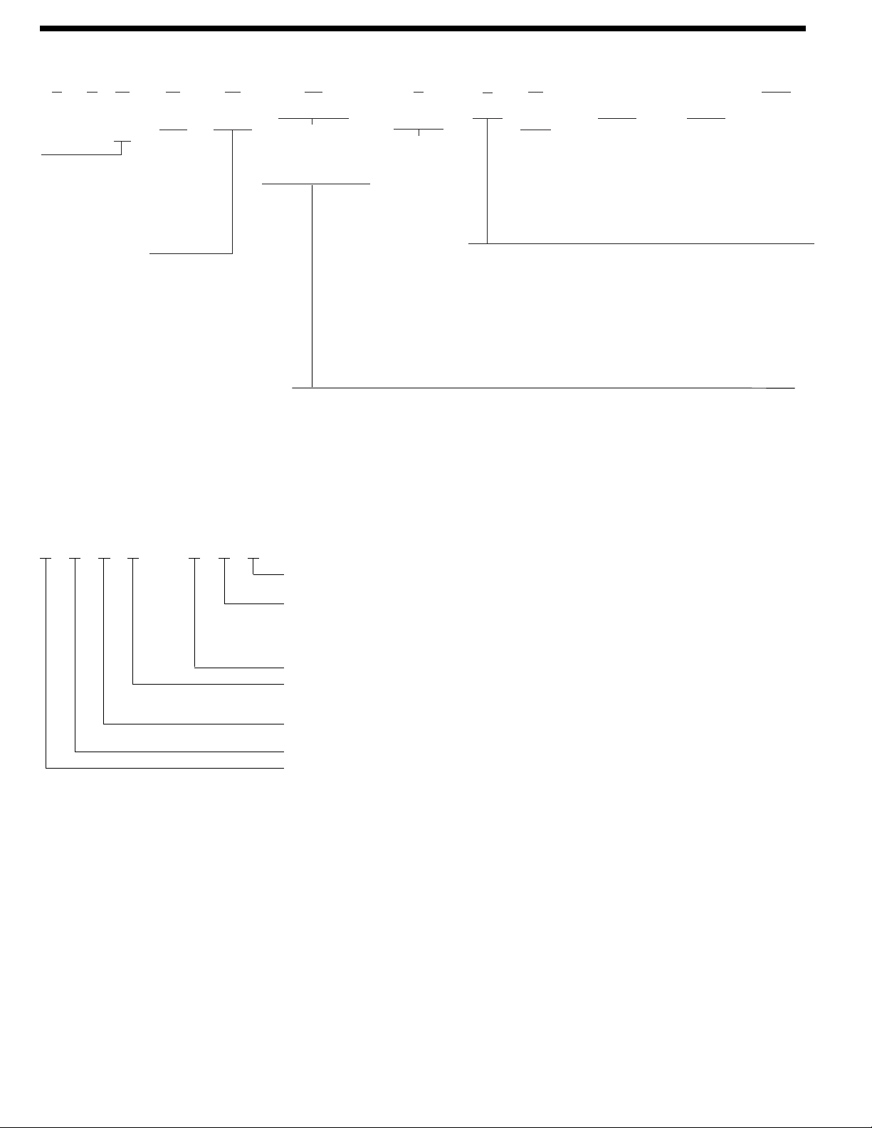
R C (-) (-) 36 A1 A
Rheem Coil Ty pe
of
Coil
Design
Series
A = 1st
Design
J= High
Efficiency
Design
(1st Design)
L= R410A
Airflow
➀
U
Nominal
Capacity
Metering Device
** = Flowcheck
Piston
(RCBA Coils)
A1 or A2 = TX Valve
(RCHJ/RCHL Coils)
Refrigerant
Connection
➂A(-)= Standard
Side
Connections
G(-) = Front
Connections
Variation
Blank = None
A = Filter/Filter Rack
B = Adapters
(78/80% Furnace)
X = Unit Has
Insulation
A
Variation
Blank = None
M = Revised
Horizontal
I = Revised
Horizontal
with
Insulation
—
031 =
Side Connect
Condensate
Drain Option
for 14” & 17”
models
OPT
B= Flowcheck
Standard Cooling/
Heat Pump
H = Expansion Valve
Heat Pump
Coil
Casing
14 = 14.0"
17 = 17.5"
21 = 21.0"
24 = 24.5"
17
—
24 = 18,000 To 24,000 BTUH
[5.27 to 7.03 kW]
36/37 = 30,000 To 36,000 BTUH
[8.79 to 10.55 kW]
48 = 42,000 To 48,000 BTUH
[12.31 to 14.06 kW]
60 = 60,000 BTUH
[17.58 kW]
NOTES: ➀ End of uncased model number.
➁ May Be Used in Horizontal Position with
the Addition of Horizontal Drain Pan Kits.
➂ Double coils RCGJ/RCHJ/RCHL-51A1
and 61A1 are not available with “F” or “H”
airflow direction (front connection).
Metering Device also available as a field installed kit. (RXCT-C**)
RCHJ—AE1
1 = Coil #1
2 = Coil #2
E = RCHJ-51A1A
Y = RCHJ-61A1A
Z = RCGJ-61A1A (Reference Only)
6 = RCHL-51A1
8 = RCHL-61A1
A = Replacement Coil
Design Type
J = High Efficiency Coil
L = R410A
Product Classification
H = Heat Pump Coil (With TX Valve)
C = Coil
R = Rheem
Current end items are:
RCHJ-AE1 RCHJ-AY1
RCHJ-AE2 RCHJ-AY2
[ ] Designates Metric Conversions
DOUBLE STACKED COILS FOR REPLACEMENT
MODEL NUMBER IDENTIFICATION
“A” Refrigerant Connection:
U = Upflow/Downflow-Left (Std.)
D = Upflow/Downflow-Right
L = Horizontal (Left)-Top
R = Horizontal (Right)-Top
➁S = Upflow/Downflow- Left or Right
“G” Refrigerant Connection:
G = Upflow/Downflow
H = Horizontal
Z = Horizontal
Page 3
Rheem Heating, Cooling and Water Heating 3
CHC
RCBA-36/37
RCGA-36A1
RCGJ-24A2
RCGA-36A2
RCHA-36A1
RCHA-36A2
RCGJ-36A1
RCGA-24A2
CHA
RCBA-24
RCGA-24A1
RCHA-24A1
RCHA-24A2
RCGJ-24A1
CHG
RCHJ-36A1
RCGJ-36A2
RCHJ-36A2
CHF (2) RCBA-60 RCHJ-51A1A
(2) RCBA-60
RCGJ-61A1A
CHJ RCBA-60
RCGA-60A1
RCGJ-60A1
RCGJ-60A2
CHL
RCBA-48
RCGA-48A1
RCHA-48A1
RCHJ-24A1
RCHJ-61A1A
RCHA-60A1
RCHJ-60A1
RCGJ-48A1
RCHJ-48A1
RCHJ-48A2
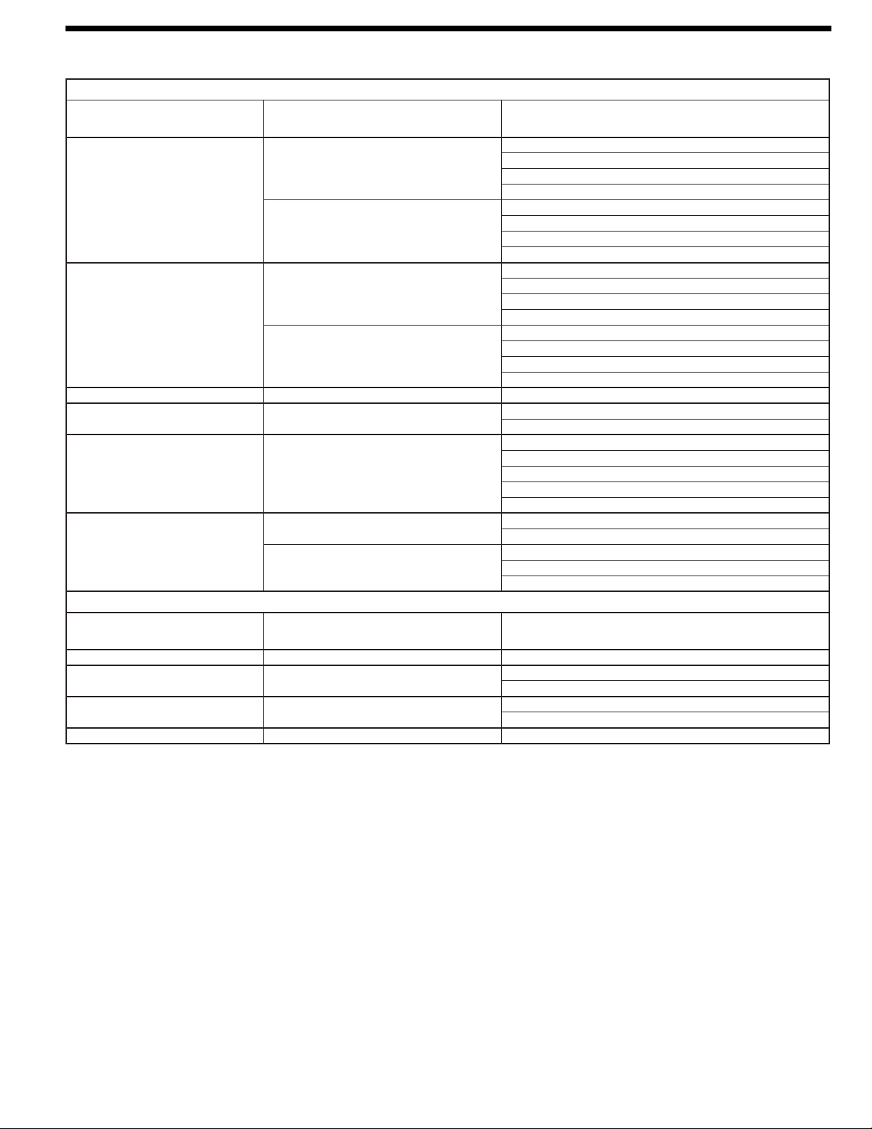
R-22 TXV KIT APPLICATION GUIDELINE
RCHJ-24A2
R-410A TXV KIT APPLICATION GUIDELINE
DHA RCBA-36/37 RCHL-24A2
DHB RCBA-48
RCHL-36A1
RCHL-36A2
DHC RCBA-60
RCHL-48A1
RCHL-48A2
DHD RCBA-60 RCHL-60A1
RCBA-36/37
RCBA-48
RCBA-60
TXV KIT #:
RXCT-
PLUS BASE COIL
MAKES REPLACEMENT COIL
FOR THESE MODELS
TXV KIT #:
RXCT-
PLUS BASE COIL
MAKES REPLACEMENT COIL
FOR THESE MODELS
RXCT- EXPANSION VALVE CONVERSION KIT FOR RCBA INDOOR COILS
Use an expansion valve kit to convert RCBA- indoor coils to RCGA-/RCGJ-/RCHA- and RCHJ- Coils
Kits may be used for conversion of side or front connect with the exception of the RXCT-CHF and RXCT-CHG, which is side connect only.
[ ] Designates Metric Conversions
Page 4
4 Rheem Heating, Cooling and Water Heating
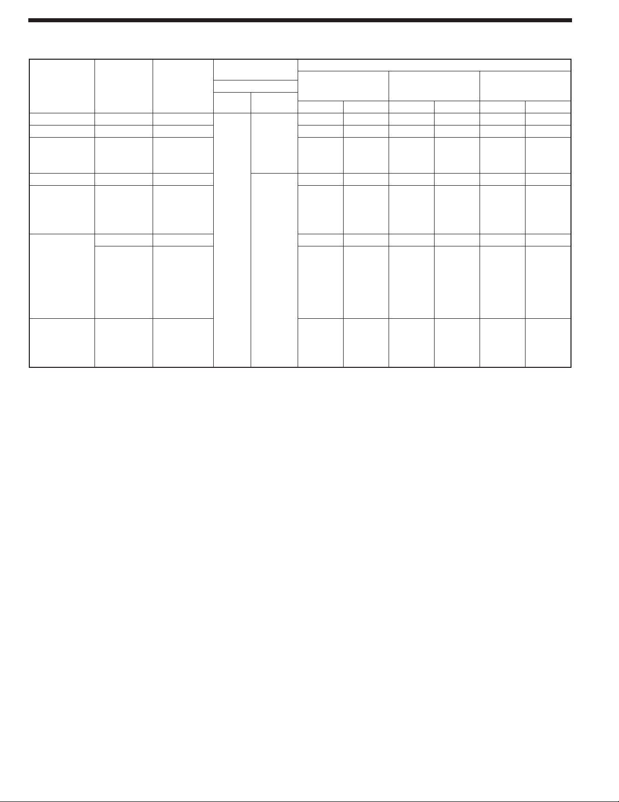
UNIT DIMENSIONS & WEIGHTS—
RCBA-/RCHJ-/RCHL- CASED AND UNCASED COILS
[ ] Designates Metric Conversions
CONNECTION
MODEL
NUMBER
RCBA-24
RCBA-36/37
RCHL-24A1
RCHJ-24A2
RCBA-48
RCHL-36A1
RCHJ-36A1
RCHJ-36A2
RCHL-36A2
RCBA-60
RCHL-48A1
RCHJ-48A2
RCHL-48A2
RCHJ-60A1
RCHJ-48A1
RCHL-60A1
RCHJ-51A1
RCHL-51A1
RCHJ-61A1
RCHL-61A1
UNCASED
COIL
“X” IN. [mm]
121/4 [311] 141/4 [356]
153/4 [400] 171/2 [445]
153/4 [400] 171/2 [445]
191/4 [489] 21 [533]
191/4 [489] 21 [533]
223/4
[578]
223/4 [578] 241/2 [622]
N/A
STANDARD
CASED COIL
“W” IN. [mm]
241/2
241/2 [622]
[622]
SIZE (IN.) [mm]
SWEAT
LIQUID
3
/8
SUCTION
I.D.
[10]
I.D.
3
/4 [19]
7
/8 [22]
UNCASED
COIL
WT. SHIP WT. WT. SHIP WT. WT. SHIP WT.
15 [6.80] 17 [7.11] 32 [14.51] 34 [15.42] 37 [16.78] 39 [17.69]
20 [9.07] 22 [9.98] 39 [17.69] 41 [18.60] 44 [19.96] 47 [21.31]
21 [9.53] 23 [10.43] 40 [18.14] 42 [19.05] 45 [20.41] 48 [21.77]RCHJ-24A1
26 [11.79] 29 [13.15] 46 [20.87] 49 [22.22] 52 [23.59] 55 [24.95]
27 [12.25] 30 [13.61] 47 [21.32] 50 [22.68] 53 [24.04] 56 [25.40]
32 [14.51] 35 [15.88] 54 [24.49] 57 [25.85] 60 [27.22] 64 [29.03]
33 [14.97] 36 [16.33] 55 [24.95] 58 [26.31] 61 [27.67] 65 [29.48]
N/A N/A 110 116 122 130
UNIT WEIGHT (LBS.) [Kg]
STANDARD
CASED COIL
CASED COIL WITH
HORIZ. DRAIN PAN
Page 5

Rheem Heating, Cooling and Water Heating 5
I153
UNIT DIMENSIONS & WEIGHTS—
RCBA-/RCHJ-/RCHL- CASED AND UNCASED COILS
(cont.)
[ ] Designates Metric Conversions
Page 6

6 Rheem Heating, Cooling and Water Heating
RCHJ-51A1
RCHL-51A1
RCHJ-61A1
RCHL-61A1
DOUBLE STACKED COILS
[ ] Designates Metric Conversions
55
55
5
55
55
55
55
55
55
55
55
55
UNIT MAY BE INSTALLED
UPFLOW OR DOWNFLOW
AIR SUPPLY.
ALL OPENINGS
IN CASING
ARE KNOCKOUTS.
REFRIGERANT &
DRAIN K.O.'S ARE
TYPICAL BOTH SIDES
OF CABINET.
CAUTION
ALL VERTICAL DRAIN CONNECTIONS
HAVE PLASTIC WEB COVERING
OPENING, WHICH MUST BE
KNOCKED OUT BEFORE
CONNECTION(S) ARE MADE.
35
[889 mm]
VAPOR LINE CONNECTION
22
[558.8 mm]
DIMENSION FROM BACK
OF CASING TO CENTER
OF KNOCKOUT (K.O.)
35 [889 mm]
DIMENSION FROM BOTTOM
OF CASING (0
OF KNOCKOUT (K.O.)
1
55
21
/8
[537 mm]–323/8
215/16 5[541 mm]–319/32 5[395 mm]
211/32 5[534 mm]–30
211/32 5[534 mm]–221/2
215/16 5[541 mm]–217/32 5[539 mm]
55
211/8
[537 mm]–201/8
55
171/2
[445 mm]
1
55
21
/8
[537 mm]–147/8
215/16 5[541 mm]–1325/32 [350 mm]
1
21
/32 5[534 mm]–121/2
) TO CENTER
/
55
[822 mm]
5
[762 mm]
55
[572 mm]
55
[511 mm]
55
[378 mm]
55
[318 mm]
LIQUID LINE CONNECTION
24
[609.6 mm]
AUXILIARY DRAIN CONNECTION
1
/4 FEMALE PIPE THREAD (NPT)
PRIMARY DRAIN CONNECTION
3
/4 FEMALE PIPE THREAD (NPT)
1
21
/32 5[534 mm]–5 [127 mm]
5
21
/16 5[541 mm]–323/32 [350 mm]
1
55
21
/8
[537 mm]–25/8
0
55
[67 mm]
Page 7

Rheem Heating, Cooling and Water Heating 7
RCBA-/RCHJ-/RCHL- SUPPLY & RETURN AIR DIMENSIONS
UPFLOW/HORIZONTAL
“G(-)” FRONT CONNECTION FOR RCBA-/RCHJ-/RCHL-
PHYSICAL DATA
DOWNFLOW
COIL
MODEL NUMBER
APPROX. DESIGN
AIRFLOW RANGE (CFM) [L/s]
FACE AREA
(SQ. FT.) [m2]
FINS/IN.
RCBA-24** 600-800 [283.1-377.6] 5.07 [.471]
18
RCHJ-/RCHL-24** 600-800 [283.1-377.6] 7.60 [.706]
RCBA-36/37** 1000-1200 [471.1-566.3] 7.60 [.706]
RCHJ-/RCHL-36** 1000-1200 [471.1-566.3] 10.13 [.941] 8
6
6
4
NUMBER
OF SLABS
2-10 Slab Coils
8RCBA-48** 1400-1600 [660.7-755.1] 10.13 [.941]
RCHJ-/RCHL-61** 1800-2000 [849.5-943.9] 12.67 [1.18]
10RCBA-60** 2000 [943.9] 12.67 [1.18]
2-10 Slab CoilsRCHJ-/RCHL-51** 1600 [755.1] 12.67 [1.18]
10RCHJ-/RCHL-48** 1400-1600 [660.7-755.1] 12.67 [1.18]
[ ] Designates Metric Conversions
NOTES: **—Indicates piston size on RCBA coils and TX valve on RCHJ-/RCHL- coils.
NOTE: Models 14 & 17 have front connections only, unless option 031 is available, which allows side connections. Side connections can also be field-
installed to models 21 & 24.
I235
Front Connection
Designated as (G) in model number.
CABINET WIDTH 14" [356]
SUPPLY AIR
RETURN AIR
“W” IN. [mm]
“D” IN. [mm]
“W” IN. [mm]
“D” IN. [mm]
13"7/3 [330]
195/8" [498]
13"7/3 [330]
197/8" [505]
17.5" [445]
161/2" [419]
195/8" [498]
161/2" [419]
197/8" [505]
CABINET WIDTH 14" [356]
SUPPLY AIR
RETURN AIR
“W” IN. [mm]
“D” IN. [mm]
“W” IN. [mm]
“D” IN. [mm]
13"7/3 [330]
197/8" [505]
13"7/3 [330]
195/8" [498]
17.5" [445]
161/2" [419]
197/8" [505]
161/2" [419]
195/8" [498]
21" [533]
20"7/3 [508]
195/8" [498]
20"7/3 [508]
197/8" [505]
21" [533]
20"7/3 [508]
197/8" [505]
20"7/3 [508]
195/8" [498]
24.5" [622]
231/2" [597]
195/8" [498]
231/2" [597]
197/8" [505]
24.5" [622]
231/2" [597]
197/8" [505]
231/2" [597]
195/8" [498]
Page 8

8 Rheem Heating, Cooling and Water Heating
NOTES: BOLD AREAS INDICATE FLUSH FIT APPLICATIONS
A — Upflow/Downflow/Horizontal Application. Horizontal application requires factory installed
horizontal drain pan or field installed horizontal drain pan accessory RXBD-DB or RXBD-DA for smaller coils in larger coil cases.
(One pan fits all).
B — Upflow/Downflow/Horizontal Application. Requires use of RXBA-AA internal coupler accessory
designated by “B” (with adapter) in coil model number.
C—Upflow/Downflow/Horizontal Application. Requires use of RXBA-AB internal coupler accessory
designated by “B” (with adapter) in coil model number.
D—Requires plenum adapter accessory RXBA-AE (Upflow application only).
E — Upflow, Upflow/Horizontal and Horizontal “Only” application requires external plenum adapter accessory RXBA-AC.
Downflow/Horizontal application requires external plenum adapter accessory RXBA-AD.
[ ] Designates Metric Conversions
CASED COIL APPLICATION
Coil can be matched to heating products as listed in table below.
NO. OF
COIL
SLABS
WIDTH IN. [mm]14[355.6]
COIL
PLENUM
WIDTH
4
14
4
17.5
4
21
6 E
17.5
6
21
6
24.5
8 E
21
8
24.5
10 E
24.5
FURNACE
78/80% UPFLOW, DOWNFLOW &
05E 07E 10A 07G 10B 12 15 04EM 06EM 07EM 07EY 09EZ 10EZ 12 ER 056 067 084 095 11 2 130 150
A
GAS FURNACE
HORIZONTAL MODELS
A & B
A & BAA & B
A
A
A&B
17.5
[444.5]
[533.4]
A & C A & C
A A A A A A
A & B A & B A & B A & B A & B A & B
A A A A A A
21
24.5
[622.3]
34" 90 PLUS UPFLOW, DOWNFLOW &
HORIZONTAL CONDENSING MODELS
A & B
A
[444.5]
GAS FURNACE
A & BAA & B
A
17.5
A & C
A & B
A & C
A & B
21
[533.4]
A & C
A & B
A & C
24.5
[622.3]
80 PLUS UPFLOW, DOWNFLOW
A & C
A
[533.4]
OIL FURNACE
& HORIZONTAL MODELS
A & C
A
A A A
21
24.5
[622.3]
D D
28
[711.2]
Page 9

Rheem Heating, Cooling and Water Heating 9
ACCESSORIES
HORIZONTAL DRAIN PAN KIT RXBD-DA
This horizontal drain pan accessory is for installation in cased
indoor cooling coils for gas or oil furnaces ONLY. This accessory
allows an upflow/downflow coil to be converted for horizontal
application. The same drain pan fits all RCBA-/RCHJ-/RCHLcoils. (Kit has metal drain pan extension).
HORIZONTAL DRAIN PAN KIT RXBD-CA
This horizontal drain pan accessory is for installation in indoor
cooling coils for air handlers ONLY. This accessory allows an
upflow/downflow coil to be converted for horizontal applications.
The same drain pan fits all RCBA-/RCHJ-/RCHL- coils. (Kit has
no metal drain pan extension.) (For RCHJ-51A1, RCHL-51A1,
RCHJ-61A1 and RCHL-61A1 two pans are required).
RXBD— DA
RHEEM
CLASSIFICATION
X = ACCESSORIES
APPLICATION
B = BLOWER UNIT
ONE SIZE (Fits All)
DESIGN SERIES
KIT TYPE
D = HORIZONTAL
DRAIN PAN
RCBA-/RCHJ-/RCHL—PRESSURE DROP
NOTES: * Air pressure drop for horizontal airflow is the same as that shown for upflow.
➀ RCHJ- coils.
For RCHJ-51 and RCHJ- double the static pressure drop shown for 10 slab coil.
GENERAL TERMS OF LIMITED WARRANTY
Rheem will furnish a replacement for any part of this product
which fails in normal use and service within the applicable
period stated, in accordance with the terms of the limited
warranty.
For Complete Details of the Limited Warranty, Including Applicable Terms
and Conditions, See Your Local Installer or Contact the Manufacturer for
a Copy.
MultiFlex Coil leaks caused by
factory defects ........................................Five (5) Years
*Any Part ..................................................Five (5) Years
*This five year limited warranty is applicable only to single-phase prod-
ucts installed in residential applications on or after January 1, 2001.
[ ] Designates Metric Conversions
Cased Coil Size In. [mm] 14 [355.6]
No. of Coil Slabs 4
Coil Cooling Size -018, -024
Coil Position (Airflow) Up
.05 [.01] 578 [272.8]
Static Pressure
Drop Through Wet
Cooling Coil In.
W.C. [kPa]
.10 [.02] 889 [419.6]
.15 [.04] 1158 [546.5] 977 [461.1] 1416 [668.3] 1244 [587.1] 1641 [774.5] 1386 [654.1] 1939 [915.1] 1605 [757.5]
.20 [.05] 1346 [635.2] 1149 [542.3] 1647 [777.3] 1413 [666.9] 1960 [925.0] 1637 [772.6] 2271 [1071.8] 1883 [888.7]
.25 [.06] 1546 [729.6] 1271 [599.8] 1876 [885.4] 1633 [770.7] 2187 [1032.1] 1826 [861.8] 2552 [1204.4] 2134 [1007.1]
.30 [.07] 1665 [785.8] 1401 [661.2] 2065 [974.6] 1784 [841.0] 2429 [1146.4] 2013 [950.0] 2890 [1363.9] 2365 [1116.2]
Down
521 [245.9]
827 [390.3]
171/2 [444.5]
6
-018➀, -024➀, -030, -036
Up
752 [354.9]
1113 [525.3]
Down
AIRFLOW CFM [L/s]
673 [317.6]
977 [461.1]
21 [533.4]
8
-030➀, -036➀, -042, -048
Up
895 [422.4]
1299 [613.1]
Down
764 [360.6]
1103 [520.6]
241/2 [622.3]
-042➀, -048➀, -060
Up
1005 [474.3]
1559 [437.8]
10
Down
885 [417.7]
1308 [617.3]
Page 10

10 Rheem Heating, Cooling and Water Heating
RCBA-/RCHJ-/RCHL- HORIZONTAL INDOOR COIL ASSEMBLY
Figure 1.
Indoor coil and drain pan set-up
for horizontal left-hand air supply.
Designated as (L) in model number.
Side connection coil shown.
Figure 2.
Indoor coil and drain pan set-up
for horizontal right-hand air supply.
Designated as (R) in model number.
Side connection coil shown.
*Foam Tape
Foam tape is factory installed on the sides of the vertical drain pan if the coil is provided in a coil casing. Foam tape is
shipped loose with uncased coils.
If uncased coil is installed vertical in a coil casing or air handler, install the foam tape on the sides of the vertical drain pan.
If installed horizontal, DO NOT install foam tape on the side of the vertical drain pan that fits into the horizontal drain pan.
Remove foam tape, if already attached, from the side of the vertical drain pan that fits into the horizontal drain pan.
If coil, vertical or horizontal, is installed in coil casing or air handler with optional “Florida Insulation,” DO NOT install foam
tape on either side of the vertical drain pan.
ACCESSORIES (continued)
I151
Page 11

Rheem Heating, Cooling and Water Heating 11
ACCESSORIES (continued)
INTERNAL COUPLER ACCESSORY RXBA-AA
AND RXBA-AB
This internal coupler accessory is for installation in cased indoor
cooling and heat pump coils. This allows a nominal size coil to
be installed in the next larger size casing to be used on a gas or
oil furnace. NOTE: This accessory is for installation in coil
casings to fit gas or oil furnaces only—this accessory must
not be used on electric furnaces or heat pump air handlers.
The RXBA-AA can be ordered factory installed by both designating the next size larger casing width and by designating a “with adapter” (B) in the coil model number.
PLENUM ADAPTER ACCESSORY RXBA-AC
AND RXBA-AD
This plenum adapter accessory is for installation on cased
indoor cooling and heat pump coils. This allows a nominal size
cased coil to be installed on the next smaller size gas or oil furnace. NOTE: This accessory is for installation on coil cas-
ings to fit gas or oil furnaces only—this accessory must not
be used on electric furnaces or heat pump air handlers.The
RXBA-AC (Upflow Only) can be ordered factory installed by
designation as “with adapter” (B) in the coil model number.
The RXBA-AD for Downflow/Horizontal applications can be
ordered separately through the order center.
PLENUM ADAPTER ACCESSORY RXBA-AE
This plenum adapter accessory is for use with the 24.5"
[622.3 mm] wide cased indoor cooling and heat pump coils. This
allows a 24.5" [622.3 mm] wide cased coil to be installed on a
28" [711.2 mm] wide oil furnace.
RXBA-AA
[ ] Designates Metric Conversions
DESIGN SERIES
A = 1ST DESIGN
KIT TYPE
A = COUPLER/COMBINATION
(ADAPTERS)
APPLICATIONS
B = BLOWER UNITS
CLASSIFICATION
X = ACCESSORIES
RHEEM
COUPLING COMBINATIONS
RCGJ-/RCHJ- HIGH EFFICIENCY COILS
COIL TO CASING
CASING TO FURNACE
COIL TO CASING
CASING TO FURNACE
CODE
A
B
C
D
E 60,000 [17.58] 24.5 [622.3]
NOMINAL
COIL
BTUH [kW]
24,000 [7.03]
36,000 [10.55]
48,000 [14.07]
24,000 [7.03]
36,000 [10.55]
36,000 [10.55]
48,000 [14.07]
60,000 [17.58]
36,000 [10.55]
48,000 [14.07]
60,000 [17.58]
CASING
WIDTH
IN. [mm]
17.5 [444.5]
21.0 [533.4]
24.5 [622.3]
21.0 [533.4]
24.5 [622.3]
17.5 [444.5]
21.0 [533.4]
24.5 [622.3]
17.5 [444.5]
21.0 [533.4]
24.5 [622.3]
FURNACE
WIDTH
IN. [mm]
17.5 [444.5]
21.0 [533.4]
24.5 [622.3]
21.0 [533.4]
24.5 [622.3]
14.0 [355.6]
17.5 [444.5]
21.0 [533.4]
14.0 [355.6]
17.5 [444.5]
21.0 [533.4]
28.0 [711.2]
INTERNAL
EXTERNAL
Internal
Internal
External
Upflow
Only
External
Downflow/
Horizontal
External
CODE
A
B 24,000 [7.03] 24.5 [622.3]
C
D
E 60,000 [17.58] 24.5 [622.3] 28.0 [711.2]
NOMINAL
COIL
BTUH [kW]
24,000 [7.03]
36,000 [10.55]
24,000 [7.03]
36,000 [10.55]
48,000 [14.07]
60,000 [17.58]
24,000 [7.03]
36,000 [10.55]
48,000 [14.07]
60,000 [17.58]
CASING
WIDTH
IN. [mm]
21.0 [533.4]
24.5 [622.3]
17.5 [444.5]
21.0 [533.4]
24.5 [622.3]
24.5 [622.3]
17.5 [444.5]
21.0 [533.4]
24.5 [622.3]
24.5 [622.3]
FURNACE
WIDTH
IN. [mm]
21.0 [533.4]
24.5 [622.3]
24.5 [622.3]
14.0 [355.6]
17.5 [444.5]
21.0 [533.4]
21.0 [533.4]
14.0 [355.6]
17.5 [444.5]
21.0 [533.4]
21.0 [533.4]
INTERNAL
EXTERNAL
Internal
Internal
External
Upflow
Only
External
Downflow/
Horizontal
External
Page 12

AIR BYPASS FRAME FOR UNCASED COILS—
(STANDARD ON ALL UNCASED COILS)
UNIT DIMENSIONS & WEIGHTS—RXBC- INDOOR COIL CASINGS
RXBC-A14XXX
When using RCGJ-61A1, RCHJ-51A1 or RCHJ-61A1
(double stacked coils) use two RXBC-A24 casings.
OPTION CODE
031 = Side Connect
CABINET WIDTH
14 = 14" [355.6 mm]
17 = 17.5" [444.5 mm]
21 = 21" [533.4 mm]
24 = 24.5" [622.3 mm]
DESIGN SERIES
A = 1st Design—Side Connections
C = Front Connection
COIL CASING
BLOWER UNIT
ACCESSORY
RHEEM
RXBC- INDOOR COIL CASING
Coil support frame is only used
when coil is installed in other than
standard coil casing.
I423
NOTES: ➀ Supply dimensions for upflow & horizontal units. This is return dimensions for downflow units.
➁ Return dimensions for upflow & horizontal units. This is supply dimensions for downflow units.
*A = Side Connection; G = Front Connection
[ ] Designates Metric Conversions
To prevent air bypass around the drain pan,
coil support frames are provided with each
uncased coil.
Before proceeding with installation, refer
to installation instructions packaged
with each model, as well as complying
with all Federal, State, Provincial, and
Local codes, regulations, and practices.
Rheem Heating,
Cooling and
Water Heating
P.O. Box 17010, Fort Smith, AR 72917
“In keeping with its policy of continuous progress and product improvement, Rheem reserves the right to make changes without notice.”
PRINTED IN U.S.A. 1-09 DC FORM NO. C11-206 REV. 14
Supersedes Form No. C11-206 Rev. 13
MODEL
NUMBER
RXBC-*14
RXBC-*17
RXBC-*21
RXBC-*24
WIDTH
“W” IN. [mm]
141/2 [356]
171/2 [445]
211/2 [533]
241/2 [622]
HEIGHT
IN. [mm]
171/2
[445]
DEPTH
IN. [mm]
22
[559]
UNIT WEIGHT
WT.
[Kg]
17 [7.11]
19 [8.62]
20 [9.07]
22 [9.98]
SHIP WT.
[Kg]
19 [8.62]
21 [5.33]
23 [10.43]
25 [11.34]
SUPPLY ➀
WIDTH
IN. [mm]
131/2 [330]
161/2 [419]
201/2 [508]
231/2 [597]
DEPTH
IN. [mm]
195/8
[498]
RETURN ➁
WIDTH
IN. [mm]
131/2 [330]
161/2 [419]
201/2 [508]
231/2 [597]
DEPTH
IN. [mm]
197/8
[505]
 Loading...