


Ruckus Wireless ICX 7150-C12P, ICX 7150-24, ICX 7150-48PF, ICX 7150-48, ICX 7150-24P Hardware Installation Manual
...Page 1

HARDWARE INSTALLATION GUIDE
Ruckus ICX 7150 Switch
Hardware Installation Guide
Part Number: 53-1004928-05
Publication Date: 21 December 2017
Page 2

Copyright Notice and Proprietary Information
Copyright 2017 Brocade Communications Systems, Inc. All rights reserved.
No part of this documentation may be used, reproduced, transmitted, or translated, in any form or by any means, electronic, mechanical,
manual, optical, or otherwise, without prior written permission of or as expressly provided by under license from Brocade.
Destination Control Statement
Technical data contained in this publication may be subject to the export control laws of the United States of America. Disclosure to
nationals of other countries contrary to United States law is prohibited. It is the reader’s responsibility to determine the applicable regulations
and to comply with them.
Disclaimer
THIS DOCUMENTATION AND ALL INFORMATION CONTAINED HEREIN (“MATERIAL”) IS PROVIDED FOR GENERAL INFORMATION
PURPOSES ONLY. BROCADE and RUCKUS WIRELESS, INC. AND THEIR LICENSORS MAKE NO WARRANTY OF ANY KIND, EXPRESS
OR IMPLIED, WITH REGARD TO THE MATERIAL, INCLUDING, BUT NOT LIMITED TO, THE IMPLIED WARRANTIES OF
MERCHANTABILITY, NON-INFRINGEMENT AND FITNESS FOR A PARTICULAR PURPOSE, OR THAT THE MATERIAL IS ERROR-FREE,
ACCURATE OR RELIABLE. BROCADE and RUCKUS RESERVE THE RIGHT TO MAKE CHANGES OR UPDATES TO THE MATERIAL AT
ANY TIME.
Limitation of Liability
IN NO EVENT SHALL BROCADE or RUCKUS BE LIABLE FOR ANY DIRECT, INDIRECT, INCIDENTAL, SPECIAL OR CONSEQUENTIAL
DAMAGES, OR DAMAGES FOR LOSS OF PROFITS, REVENUE, DATA OR USE, INCURRED BY YOU OR ANY THIRD PARTY, WHETHER
IN AN ACTION IN CONTRACT OR TORT, ARISING FROM YOUR ACCESS TO, OR USE OF, THE MATERIAL.
Trademarks
Ruckus Wireless, Ruckus, the bark logo, BeamFlex, ChannelFly, Dynamic PSK, FlexMaster, Simply Better Wireless, SmartCell, SmartMesh,
SmartZone, Unleashed, ZoneDirector and ZoneFlex are trademarks of Ruckus Wireless, Inc. in the United States and in other countries.
Brocade, the B-wing symbol, MyBrocade, and ICX are trademarks of Brocade Communications Systems, Inc. in the United States and in
other countries. Other trademarks may belong to third parties.
2 Part Number: 53-1004928-05
Ruckus ICX 7150 Switch Hardware Installation Guide
Page 3

Contents
Preface..........................................................................................................................................................................................................7
Document Conventions..........................................................................................................................................................................7
Notes, Cautions, and Warnings.......................................................................................................................................................7
Command Syntax Conventions..............................................................................................................................................................7
Document Feedback..............................................................................................................................................................................8
Ruckus Product Documentation Resources...........................................................................................................................................8
Online Training Resources...................................................................................................................................................................... 8
Contacting Ruckus Customer Services and Support..............................................................................................................................9
What Support Do I Need?...............................................................................................................................................................9
Open a Case...................................................................................................................................................................................9
Self-Service Resources................................................................................................................................................................... 9
About This Document..................................................................................................................................................................................11
Supported hardware and software....................................................................................................................................................... 11
What's new in this document............................................................................................................................................................... 12
Device Overview..........................................................................................................................................................................................13
Hardware features................................................................................................................................................................................13
License options....................................................................................................................................................................................14
Port-side view...................................................................................................................................................................................... 15
Nonport-side view................................................................................................................................................................................17
Device management options................................................................................................................................................................19
LRM Adapter support.......................................................................................................................................................................... 19
Preparing for the Installation........................................................................................................................................................................ 21
Safety precautions............................................................................................................................................................................... 21
General precautions......................................................................................................................................................................21
ESD precautions...........................................................................................................................................................................21
Power precautions........................................................................................................................................................................22
Lifting and weight-related precautions...........................................................................................................................................22
Laser precautions......................................................................................................................................................................... 23
Facility requirements.............................................................................................................................................................................23
Quick installation checklist....................................................................................................................................................................24
Pre-installation tasks..................................................................................................................................................................... 24
Installation and initial configuration................................................................................................................................................ 24
Shipping carton contents..................................................................................................................................................................... 26
Mounting the Device....................................................................................................................................................................................27
Mounting options................................................................................................................................................................................. 27
Precautions specific to mounting..........................................................................................................................................................27
Mounting on a desktop or flat surface.................................................................................................................................................. 28
Mounting the compact device with a magnet....................................................................................................................................... 30
Attaching the magnet sheet to the device..................................................................................................................................... 31
Mounting the device on a metal surface or metal wall....................................................................................................................32
Mounting the device under a metal desk.......................................................................................................................................34
Mounting the compact device under a fixed surface.............................................................................................................................36
Mounting the compact device directly on a wall................................................................................................................................... 39
Mounting on a wall using the wall mount brackets................................................................................................................................43
Ruckus ICX 7150 Switch Hardware Installation Guide
Part Number: 53-1004928-05 3
Page 4

Mounting on a two-post rack............................................................................................................................................................... 48
Installing the 1U, 1.5U, and 2U Universal Kit for Four Post Racks (XBR-R000295)................................................................................53
Time and items required.......................................................................................................................................................................54
Parts list...............................................................................................................................................................................................54
Flush-front mounting the device in the rack.......................................................................................................................................... 55
Attaching the front brackets..........................................................................................................................................................56
Attaching the bracket extensions to the device............................................................................................................................. 57
Installing the device in the rack......................................................................................................................................................58
Attaching the rear brackets to the extensions................................................................................................................................59
Attaching the rear brackets to the rack posts................................................................................................................................61
Flush-rear (recessed) mounting the device in the rack.......................................................................................................................... 62
Attaching the front brackets to the rear of the device.................................................................................................................... 62
Attaching the bracket extensions to the front of the device............................................................................................................63
Installing the device in the rack......................................................................................................................................................64
Attaching the rear brackets to the bracket extensions at the front of the device............................................................................ 65
Attaching the rear brackets to the front rack posts........................................................................................................................67
Connecting ICX 7150 Devices in a Stack.....................................................................................................................................................69
Stacking configuration requirements.....................................................................................................................................................69
ICX 7150 stacking ports.......................................................................................................................................................................69
ICX 7150 stacking topologies...............................................................................................................................................................71
Initial Setup and Verification.........................................................................................................................................................................75
Items required......................................................................................................................................................................................75
Providing power to the device.............................................................................................................................................................. 75
Establishing a first-time connection to the console port........................................................................................................................76
Recovering from a lost password..................................................................................................................................................78
Configuring an IP address for the device.............................................................................................................................................. 79
Customizing the host name and chassis name ....................................................................................................................................79
Setting the date and time..................................................................................................................................................................... 80
Establishing a connection to the out-of-band management port...........................................................................................................80
Getting in-band access........................................................................................................................................................................ 81
Verifying the correct operation..............................................................................................................................................................81
Backing up the running configuration................................................................................................................................................... 81
Installing Transceivers and Cables............................................................................................................................................................... 83
Time and items required.......................................................................................................................................................................83
Precautions specific to transceivers and cables....................................................................................................................................83
Managing cables..................................................................................................................................................................................84
Installing the Ethernet RJ-45 cables..................................................................................................................................................... 84
Cleaning the fiber-optic connectors......................................................................................................................................................86
Installing a new fiber-optic transceiver.................................................................................................................................................. 86
Cabling a fiber-optic transceiver........................................................................................................................................................... 87
Replacing a fiber-optic transceiver........................................................................................................................................................88
Monitoring the Device..................................................................................................................................................................................91
Interpreting port-side LEDs.................................................................................................................................................................. 91
System LEDs................................................................................................................................................................................ 93
OOB LED......................................................................................................................................................................................97
RJ-45 Ethernet port status LED in default mode........................................................................................................................... 97
Interpreting nonport-side LEDs.............................................................................................................................................................98
Pinging an IP address.......................................................................................................................................................................... 98
4 Part Number: 53-1004928-05
Ruckus ICX 7150 Switch Hardware Installation Guide
Page 5

Tracing a route..................................................................................................................................................................................... 98
Digital optical monitoring...................................................................................................................................................................... 99
Monitoring power and cooling.............................................................................................................................................................. 99
Ruckus ICX 7150 Switch Technical Specifications..................................................................................................................................... 101
System specifications.........................................................................................................................................................................101
Ethernet............................................................................................................................................................................................. 102
LEDs..................................................................................................................................................................................................102
Other................................................................................................................................................................................................. 103
Weight and physical dimensions.........................................................................................................................................................103
Environmental requirements............................................................................................................................................................... 103
Power supply specifications (per PSU)............................................................................................................................................... 104
Power consumption (idle configuration).............................................................................................................................................. 105
Power consumption (typical configuration)......................................................................................................................................... 106
Power consumption (maximum configuration).................................................................................................................................... 107
Data port specifications (Ethernet)......................................................................................................................................................108
Serial port specifications (pinout RJ-45)..............................................................................................................................................109
Serial port specifications (protocol).....................................................................................................................................................109
Memory specifications........................................................................................................................................................................109
Regulatory compliance (EMC)............................................................................................................................................................ 110
Regulatory compliance (safety)...........................................................................................................................................................110
Regulatory compliance (environmental).............................................................................................................................................. 110
Regulatory Statements.............................................................................................................................................................................. 111
CE statement..................................................................................................................................................................................... 111
China ROHS...................................................................................................................................................................................... 111
BSMI statement (Taiwan)....................................................................................................................................................................111
Canadian requirements...................................................................................................................................................................... 112
China CCC statement........................................................................................................................................................................ 112
Europe and Australia (CISPR 32 Class A Warning)..............................................................................................................................113
FCC warning (US only)....................................................................................................................................................................... 113
Germany statement............................................................................................................................................................................113
KCC statement (Republic of Korea)....................................................................................................................................................113
VCCI statement..................................................................................................................................................................................113
Cautions and Danger Notices....................................................................................................................................................................115
Cautions............................................................................................................................................................................................ 115
General cautions.........................................................................................................................................................................115
Electrical cautions....................................................................................................................................................................... 117
Danger Notices.................................................................................................................................................................................. 118
General dangers......................................................................................................................................................................... 119
Electrical dangers........................................................................................................................................................................119
Dangers related to equipment weight..........................................................................................................................................121
Laser dangers.............................................................................................................................................................................122
Ruckus ICX 7150 Switch Hardware Installation Guide
Part Number: 53-1004928-05 5
Page 6

6 Part Number: 53-1004928-05
Ruckus ICX 7150 Switch Hardware Installation Guide
Page 7

Preface
• Document Conventions.............................................................................................................................................7
• Command Syntax Conventions................................................................................................................................. 7
• Document Feedback.................................................................................................................................................8
• Ruckus Product Documentation Resources.............................................................................................................. 8
• Online Training Resources......................................................................................................................................... 8
• Contacting Ruckus Customer Services and Support................................................................................................. 9
Document Conventions
The following tables list the text and notice conventions that are used throughout this guide.
TABLE 1 Text conventions
Convention Description Example
monospace
bold User interface (UI) components such
italics
Identifies command syntax
examples.
as screen or page names, keyboard
keys, software buttons, and field
names
Publication titles Refer to the
device(config)# interface ethernet 1/1/6
On the Start menu, click All Programs.
Ruckus Small Cell Release Notes
for more information
Notes, Cautions, and Warnings
Notes, cautions, and warning statements may be used in this document. They are listed in the order of increasing severity of potential
hazards.
NOTE
A NOTE provides a tip, guidance, or advice, emphasizes important information, or provides a reference to related information.
CAUTION
A CAUTION statement alerts you to situations that can be potentially hazardous to you or cause damage to hardware, firmware,
software, or data.
DANGER
A DANGER statement indicates conditions or situations that can be potentially lethal or extremely hazardous to you. Safety labels
are also attached directly to products to warn of these conditions or situations.
Command Syntax Conventions
Bold and italic text identify command syntax components. Delimiters and operators define groupings of parameters and their logical
relationships.
Convention
bold text Identifies command names, keywords, and command options.
Description
Ruckus ICX 7150 Switch Hardware Installation Guide
Part Number: 53-1004928-05 7
Page 8

Preface
Document Feedback
Convention Description
italic
text Identifies a variable.
[ ]
{ x | y | z } A choice of required parameters is enclosed in curly brackets separated by vertical bars. You must select
x | y A vertical bar separates mutually exclusive elements.
< >
... Repeat the previous element, for example,
\ Indicates a “soft” line break in command examples. If a backslash separates two lines of a command input,
Syntax components displayed within square brackets are optional.
Default responses to system prompts are enclosed in square brackets.
one of the options.
Nonprinting characters, for example, passwords, are enclosed in angle brackets.
member[member
enter the entire command at the prompt without the backslash.
...].
Document Feedback
Ruckus is interested in improving its documentation and welcomes your comments and suggestions.
You can email your comments to Ruckus at: docs@ruckuswireless.com
When contacting us, please include the following information:
• Document title and release number
• Document part number (on the cover page)
• Page number (if appropriate)
• For example:
– Ruckus Small Cell Alarms Guide SC Release 1.3
– Part number: 800-71306-001
– Page 88
Ruckus Product Documentation Resources
Visit the Ruckus website to locate related documentation for your product and additional Ruckus resources.
Release Notes and other user documentation are available at https://support.ruckuswireless.com/documents. You can locate
documentation by product or perform a text search. Access to Release Notes requires an active support contract and Ruckus Support
Portal user account. Other technical documentation content is available without logging into the Ruckus Support Portal.
White papers, data sheets, and other product documentation are available at https://www.ruckuswireless.com.
Online Training Resources
To access a variety of online Ruckus training modules, including free introductory courses to wireless networking essentials, site surveys,
and Ruckus products, visit the Ruckus Training Portal at https://training.ruckuswireless.com.
8 Part Number: 53-1004928-05
Ruckus ICX 7150 Switch Hardware Installation Guide
Page 9

Preface
Contacting Ruckus Customer Services and Support
Contacting Ruckus Customer Services and Support
The Customer Services and Support (CSS) organization is available to provide assistance to customers with active warranties on their
Ruckus Networks products, and customers and partners with active support contracts.
For product support information and details on contacting the Support Team, go directly to the Support Portal using https://
support.ruckuswireless.com, or go to https://www.ruckuswireless.com and select Support.
What Support Do I Need?
Technical issues are usually described in terms of priority (or severity). To determine if you need to call and open a case or access the selfservice resources use the following criteria:
• Priority 1 (P1)—Critical. Network or service is down and business is impacted. No known workaround. Go to the Open a Case
section.
• Priority 2 (P2)—High. Network or service is impacted, but not down. Business impact may be high. Workaround may be available.
Go to the Open a Case section.
• Priority 3 (P3)—Medium. Network or service is moderately impacted, but most business remains functional. Go to the Self-Service
Resources section.
• Priority 4 (P4)—Low. Request for information, product documentation, or product enhancements. Go to the Self-Service
Resources section.
Open a Case
When your entire network is down (P1), or severely impacted (P2), call the appropriate telephone number listed below to get help:
• Continental United States: 1-855-782-5871
• Canada: 1-855-782-5871
• Europe, Middle East, Africa, and Asia Pacific, toll-free numbers are available at https://support.ruckuswireless.com/contact-us and
Live Chat is also available.
Self-Service Resources
The Support Portal at https://support.ruckuswireless.com/contact-us offers a number of tools to help you to research and resolve problems
with your Ruckus products, including:
• Technical Documentation—https://support.ruckuswireless.com/documents
• Community Forums—https://forums.ruckuswireless.com/ruckuswireless/categories
• Knowledge Base Articles—https://support.ruckuswireless.com/answers
• Software Downloads and Release Notes—https://support.ruckuswireless.com/software
• Security Bulletins—https://support.ruckuswireless.com/security
Using these resources will help you to resolve some issues, and will provide TAC with additional data from your troubleshooting analysis if
you still require assistance through a support case or RMA. If you still require help, open and manage your case at https://
support.ruckuswireless.com/case_management
Ruckus ICX 7150 Switch Hardware Installation Guide
Part Number: 53-1004928-05 9
Page 10

10 Part Number: 53-1004928-05
Ruckus ICX 7150 Switch Hardware Installation Guide
Page 11

About This Document
• Supported hardware and software.......................................................................................................................... 11
• What's new in this document.................................................................................................................................. 12
Supported hardware and software
This document is applicable for the various Ruckus ICX 7150 Ethernet switch models. The following tables list the device models and rack
mount kits supported.
TABLE 2 OS-dependent models
Model number Short description Introduced (OS) Currently supported
(OS)
ICX 7150-48ZP Sixteen 2.5G and thirty-two 1G Copper ports with
eight SFP+ 1G/10-GbE ports - four are optical
stacking or uplink ports, and four are uplink ports
only
ICX 7150-C12P Twelve GbE (124 W) PoE+ ports with two 1-GbE
uplink ports and two SFP+ 10-GbE optical stacking
or uplink ports
ICX 7150-24 Twenty-four GbE non-PoE ports with two 1-GbE
uplink ports and four SFP+ 10-GbE optical
stacking or uplink ports
ICX 7150-24P Twenty-four GbE (370 W) PoE+ ports with two 1-
GbE uplink ports and four SFP+ 10-GbE optical
stacking or uplink ports
ICX 7150-48 Forty-eight GbE non-PoE ports with two 1-GbE
uplink ports and four SFP+ 10-GbE optical
stacking or uplink ports
ICX 7150-48P Forty-eight GbE (370 W) PoE+ ports with two 1-
GbE uplink ports and four SFP+ 10-GbE optical
stacking or uplink ports
ICX 7150-48PF Forty-eight GbE (740 W) PoE+ ports with two 1-
GbE uplink ports and four SFP+ 10-GbE optical
stacking or uplink ports
FastIron 08.0.61 Yes hot-swap fan tray (up to 2
FastIron 08.0.60 Yes Fanless
FastIron 08.0.60 Yes Fanless
FastIron 08.0.60 Yes Two built-in fans
FastIron 08.0.60 Yes Fanless
FastIron 08.0.60 Yes Two built-in fans
FastIron 08.0.60 Yes Three built-in fans
Notes
per switch)
Mountable on a desktop,
rack, or wall
Mountable on a desktop,
rack, wall, under a fixed
surface, under a desk,
under a shelf, or using a
magnet
Mountable on a desktop,
rack, or wall
Support fanless mode
Mountable on a desktop,
rack, or wall
Mountable on a desktop,
rack, or wall
Support fanless mode
Mountable on a desktop,
rack, or wall
Mountable on a desktop,
rack, or wall
Ruckus ICX 7150 Switch Hardware Installation Guide
Part Number: 53-1004928-05 11
Page 12

About This Document
What's new in this document
NOTE
For ICX 7150-C12P, ICX 7150-24, ICX 7150-24P, ICX 7150-48, ICX 7150-48P, and ICX 7150-48PF, the AC power supply and
fans are integrated with the device. The power supply or the fans are not field replaceable units (FRUs).
TABLE 3 Rack mount kits
Part number Short description Notes
ICX6400-C12-MGNT Magnet mount kit for ICX 7150-C12P. This is not a rack mount kit. It is a
magnet which could be used on a rack or on any surface that is magnetic
such as a metal desk or cabinet
ICX7000-C12-RMK Rack mount kit for ICX 7150-C12P on 2-post racks Not included with the device. Optionally
ICX7000-C12-WMK Wall / under desk mount kit for ICX 7150-C12P Not included with the device. Optionally
ICX7000-RMK Rack mount kit for 2-post racks Included with 24-port and 48-port ICX 7150
XBR-R000295 Universal rack mount kit for 4-post racks Not included with the device. Optionally
RMK-LRM-ADP Rack mount kit for LRM adapters. 1RU shelf can accommodate up to eight
LRM adapters.
Not included with the device. Optionally
orderable.
orderable.
orderable.
models.
orderable.
Not included with the device. Optionally
orderable.
TABLE 4 Supported Adapter
Adapter Type Short description Notes
10G LRM SFP +
Adapter
10GE SFP+ adapter for LRM optics Not included with the device. Optionally
orderable.
What's new in this document
The following table includes descriptions of new information added to this guide for the FastIron 08.0.70 release.
TABLE 5 Summary of enhancements in FastIron release 08.0.70
Feature Description Described in
Status Button Support You must press the status mode selection button
to select the status mode to display the
corresponding status on the individual port status
LED.
Updates to LED Several updates to the LED status. Refer to the topics under Interpreting port-side
Status mode LEDs on page 94
LEDs on page 91.
12 Part Number: 53-1004928-05
Ruckus ICX 7150 Switch Hardware Installation Guide
Page 13

Device Overview
• Hardware features...................................................................................................................................................13
• License options....................................................................................................................................................... 14
• Port-side view......................................................................................................................................................... 15
• Nonport-side view................................................................................................................................................... 17
• Device management options................................................................................................................................... 19
• LRM Adapter support..............................................................................................................................................19
Hardware features
The Ruckus ICX 7150 offers the following hardware features and capabilities:
• ICX 7150 Z-series new for this release have the following features:
– 16 2.5G+ Copper ports , that support 100M/1G/2.5G operation.
– 32 1G Copper ports, that support 10M/100M/1G operation.
– 8 SFP+ Fiber Ports supporting 1G/10G operation , in which the first 4 ports can be configured as stacking ports and the last
4 ports can be used for uplink/user port.
– The ports 1/2/1 and 1/2/3 comes up in 10G speed by default.
– The other ports comes up in 1G speed default , enabling 10G on these ports requires a software license. The ports 1/2/1
through 1/2/4 can be configured as stacking port or as user/uplink ports, where as 1/2/5 through 1/2/8 can be configured as
user/uplink ports.
– The first 16 ports complies with the power-over-HDBase T and each port can provide up to 90W.
– The 32 1G Copper ports complies with the IEEE 802.3af/at standard.
• The table below lists the ICX 7150 switch models with 12, 24, or 48 auto-negotiating 10/100/1000 Mbps full duplex RJ-45 ports
that can be used for downlink. These ports reside on slot 1 of the switch and can be non-PoE, PoE/POE+, or PoE+ ports.
TABLE 6 Switch model and corresponding IO port configurations
Switch model Down Link
Ports
ICX 7150-48 48x1G Copper NA NA 2x1G Copper + 4xSFP + 2xSFP+
ICX 7150-48P 48x1G Copper 48 370W 2x1G Copper + 4xSFP+ 2xSFP+
ICX 7150-48PF 48x1G Copper 48 740W 2x1G Copper +4xSFP+ 2xSFP+
ICX 7150-24 24x1G Copper NA NA 2x1G Copper + 4xSFP+ 2xSFP+
ICX 7150-24P 24x1G Copper 24 370W 2x1G Copper + 4xSFP+ 2xSFP+
ICX 7150-C12P 12x1G Copper 12 124W 2x1G Copper + 2xSFP 2xSFP+
ICX 7150-48ZP 16x2.5G
Copper 32x
1G Copper
• Two 10/100/1000Base-T full duplex RJ-45 ports that can be used as uplink data ports. These ports reside on slot 2 of the switch.
• Two or four SFP+ optical 10-Gbps full duplex ports that can be used as stacking or uplink data ports. These ports reside on slot 3
of the switch.
• 10-GbE SFP+ dongle for LRM optic (Now supported in this release and onwards).
• Switch Port Extender (PE) mode (not supported currently).
• Maximum two FRUs power supply units.
Ruckus ICX 7150 Switch Hardware Installation Guide
Part Number: 53-1004928-05 13
PoE
Ports
48 1480W 4xSFP + 8xSFP 4xSFP+
PoE Power Up Link / Stacking Ports Stacking Ports
Page 14

Device Overview
License options
• Maximum two FRU fans for cooling the system with sides-to-back airflow.
• System LEDs
– Power status
– DIAG status
– Master/Slave status
– Cloud management status (not enabled currently).
– Software update status (not enabled currently).
• Status mode LEDs (not enabled currently).
– Port link status mode
– Port speed status mode
– PoE status mode
– Member ID status mode
– USB modes
• Management interfaces
– Mode switch button (not enabled currently)
– Reset button
– Out-of-band (OOB) GbE management port
– USB 2.0 general purpose Type-A port for file transfer with removable media (removable media not included with the device)
– Type-C USB console port (Type-C USB cable not included with the device)
– RS-232 console port with RJ-45 form factor (RJ-45 console cable not included with the device)
License options
The following table displays Ruckus ICX 7150 part number and license information available when upgrading to a licensed feature set. The
licensed feature set includes the Premium Layer 3 license, and the Ports on Demand license. When upgrading to a licensed feature set, a
Certificate of Entitlement (CoE) is shipped to you upon purchase of the license. The CoE is a “proof of purchase” for any features that have
been purchased. The CoE is a .PDF certificate that has a unique serial number. One CoE is issued for each feature license that is
purchased. Refer to the
TABLE 7 Ruckus ICX 7150 SKU and license information
Part Number for Upgrades License Name Description
BR-ICX-7150-41U210-P-01 2X10G CoE license to upgrade any ICX 7150 24-port or 48-port model from 4x1G
BR-ICX-7150-210U410R-P-01 4X10GR CoE license to upgrade any ICX 7150 24-port or 48-port model from 2x1G
BR-ICX-7150-41U410R-P-01 4X10GR CoE license to upgrade any ICX 7150 24-port or 48-port model from 4x1G
BR-ICX-7150C-21U210R-P-01 2X10GR CoE license to upgrade the ICX 7150-C12P switch from 2x1G SFP to a
BR-ICX-7150Z210U810R-P-01 8X10GR CoE license to upgrade an ICX 7150-48ZP Z-Series switch from 6x1G SFP
Brocade FastIron Software Licensing Guide
for more details.
SFP to a 2x1G SFP and 2x10G SFP+ uplink or stacking ports.
SFP and 2x10G SFP+ to a 4x10G SFP+ uplink or stacking ports. Two
default ports are available for stacking. Layer 3 Premium license features
(OSPF, VRRP, PIM, PBR) are also included.
SFP to a 4x10G SFP+ uplink or stacking ports. Two default ports are
available for stacking. Layer 3 Premium license features (OSPF, VRRP, PIM,
PBR) are also included.
2x10G SFP+ uplink or stacking ports. Layer 3 Premium license features
(OSPF, VRRP, PIM, PBR) are also included.
& 2x10G SFP+ to 8x10G SFP+ uplink or stacking ports. Layer 3 Premium
license features (OSPF, VRRP, PIM, PBR) are also included.
14 Part Number: 53-1004928-05
Ruckus ICX 7150 Switch Hardware Installation Guide
Page 15

Port-side view
FIGURE 1 Port-side view of ICX 7150-C12P
Device Overview
Port-side view
1. Type-C USB console port
2. Port status mode selection button and LEDs
3. System LEDs
4. Slot 1 (10/100/1000 Mbps RJ-45 downlink) ports
5. Slot 2 (10/100/1000 Mbps RJ-45 uplink) ports (half-duplex is not support
on these ports)
6. Slot 3 (SFP+ uplink or stacking ports)
7. SFP+ Port X2 status LED
8. SFP+ Port X1 status LED
9. Reserved for future use
10. RJ-45 uplink port C2 RX/TX activity LED
11. Reserved for future use
12. RJ-45 downlink port 8 RX/TX activity LED
13. Out-of-band management port (RJ-45) with 2 LEDs
a. Left LED - Off: Link-down, Steady green: Link-up, and Blinking green:
when there is RX/TX activity
b. Right LED - Off: when offline or linked at 10/100Mbps, Blinking green:
when there is RX/TX activity
14. USB port
15. RJ-45 console port
16. Reset button
Ruckus ICX 7150 Switch Hardware Installation Guide
Part Number: 53-1004928-05 15
Page 16

Device Overview
Port-side view
FIGURE 2 Port-side view of ICX 7150-24 and ICX 7150-24P
1. Type-C USB console port
2. Port status mode selection button and LEDs
3. System LEDs
4. RJ-45 downlink port 17 status LED
5. RJ-45 downlink port 17 RX/TX activity LED
6. RJ-45 uplink port C1 status LED
7. RJ-45 uplink port C1 RX/TX activity LED
8. SFP+ port X1 status LED
9. SFP+ port X2 status LED
10. Slot 3 (SFP+ uplink or stacking) ports
FIGURE 3 Port-side view of ICX 7150-48, ICX 7150-48P, and ICX 7150-48PF
11. Slot 2 (10/100/1000 Mbps RJ-45 uplink) ports (half-duplex is not support
on these ports)
12. Slot 1 (10/100/1000 Mbps RJ-45 downlink) ports
13. USB port
14. Out-of-band management port (RJ-45) with 2 LEDs
a. Left LED - Off: Link-down, Steady green: Link-up, and Blinking green:
when there is RX/TX activity
b. Right LED - Off: when offline or linked at 10/100Mbps, Blinking green:
when there is RX/TX activity
15. RJ-45 console port
16. Reset button
1. Type-C USB console port
2. Port status mode selection button and LEDs
3. System LEDs
4. RJ-45 downlink port 29 status LED
5. RJ-45 downlink port 29 RX/TX activity LED
6. RJ-45 uplink port C1 status LED
7. RJ-45 uplink port C1 RX/TX activity LED
8. SFP+ port X1 status LED
9. SFP+ port X2 status LED
10. Slot 3 (SFP+ uplink or stacking) ports
16 Part Number: 53-1004928-05
11. Slot 2 (10/100/1000 Mbps RJ-45 uplink) ports (half-duplex is not support
on these ports)
12. Slot 1 (10/100/1000 Mbps RJ-45 downlink) ports 1-48
13. USB port
14. Out-of-band management port (RJ-45) with 2 LEDs
a. Left LED - Off: Link-down, Steady green: Link-up, and Blinking green:
when there is RX/TX activity
b. Right LED - Off: when offline or linked at 10/100Mbps, Blinking green:
when there is RX/TX activity
15. Reset button
Ruckus ICX 7150 Switch Hardware Installation Guide
Page 17

FIGURE 4 Port-side view of ICX 7150-48ZP
Device Overview
Nonport-side view
1. Type-C USB console port
2. Pushbutton to cycle through Mode LEDs
3. Mode LEDs
4. System LEDs
5. Reset Button
6. Venting holes
7. Logo and Model name
8. SFP+ Fiber Stacking/Uplink ports
Nonport-side view
FIGURE 5 Nonport-side view of ICX 7150-C12P
9. 1G PoE-2 pair user Ports 17 - 48
10. 2.5G PoE-2 pair user Ports 1-16
11. Type-A USB port
12. Out-of-band management port (RJ-45) with 2 LEDs
a. Left LED - Off: Link-down, Steady green: Link-up, and Blinking green:
when there is RX/TX activity
b. Right LED - Off: when offline or linked at 10/100Mbps, Blinking green:
when there is RX/TX activity
1. Kensington security slot
2. AC power supply socket
FIGURE 6 Nonport-side view of ICX 7150-24
1. AC power supply socket
Ruckus ICX 7150 Switch Hardware Installation Guide
Part Number: 53-1004928-05 17
Page 18

Device Overview
Nonport-side view
FIGURE 7 Nonport-side view of ICX 7150-48
1. Management console port - RJ-45 2. AC power supply socket
FIGURE 8 Nonport-side view of ICX 7150-24P and ICX 7150-48P
1. Fan 1
2. Fan 2
FIGURE 9 Nonport-side view of ICX 7150-48PF
1. Fan 1
2. Fan 2
3. Fan 3
FIGURE 10 Nonport-side view of ICX 7150-48ZP
3. Management console port - RJ-45 (available in the front panel for ICX
7150-24P)
4. AC power supply socket
4. Management console port - RJ-45
5. AC power supply socket
1. Fan 1
2. Fan 2
3. Management console port - RJ-45
18 Part Number: 53-1004928-05
4. 920W PSU with 740W of PoE budget
5. 920W PSU with 740W of PoE budget
Ruckus ICX 7150 Switch Hardware Installation Guide
Page 19

Device Overview
LRM Adapter support
Device management options
You can use the management functions built into the device to monitor the topology, port status, physical status, and other information to
help you analyze switch performance and to accelerate system debugging. The device automatically performs power-on self-test (POST)
each time it is turned on. Any errors are recorded in the syslog messages.
You can manage the device using any of the management options listed in the following table.
TABLE 8 Management options for the device
Management tool Out-of-band support Reference documents
Command line interface (CLI) Ethernet, serial connection, or USB console
Standard SNMP applications Ethernet or serial connection
Brocade FastIron Web Management Interface Ethernet or connection via IP address
Brocade FastIron Command Reference Guide
Feature-based
Unified IP MIB Reference Guide
Brocade FastIron Web Management Interface
User Guide
Configuration Guides
NOTE
Not all FastIron features are
supported via the web management
interface.
Brocade Network Advisor (BNA)
NOTE
BNA must be purchased separately.
Ethernet or serial connection Brocade Network Advisor documentation set
LRM Adapter support
Some ICX switches do not support Long Reach Module (LRM) optics on 10G fiber ports. LRM adapter can connect to any 10G fiber ports
of the ICX switch. It has two 10G fiber ports and both ports can be used at the same time.
The LRM Adapter is supported on all 10G fiber ports for all models of the ICX7150 Family of switches. Below is the front view of the LRM
adapter and the SPF+ Optic module with copper pigtail.
Ruckus ICX 7150 Switch Hardware Installation Guide
Part Number: 53-1004928-05 19
Page 20

Device Overview
LRM Adapter support
FIGURE 11 LRM Adapter front view
1. Port Status LEDs (see per Port LED status definition below)
a. Amber off, Green off : No Power
b. Amber on, Green off : Link down
FIGURE 12 SPF+ Optic module with copper pigtail
NOTE
The LRM adapter is used to support LRM optics on the ICX7750, ICX7250 and ICX7150 switches. The ICX7450 support LRM
optics natively.
c. Amber off, Green on : Link Up
d. Amber off, Green Blinking : Link activity
2. Panel Label
20 Part Number: 53-1004928-05
Ruckus ICX 7150 Switch Hardware Installation Guide
Page 21

Preparing for the Installation
• Safety precautions...................................................................................................................................................21
• Facility requirements................................................................................................................................................23
• Quick installation checklist.......................................................................................................................................24
• Shipping carton contents........................................................................................................................................ 26
Safety precautions
When using this product, observe all danger, caution, and attention notices in this manual. The safety notices are accompanied by symbols
that represent the severity of the safety condition
Refer to Cautions and Danger Notices at the end of this guide for translations of safety notices for this product.
General precautions
DANGER
The procedures in this manual are for qualified service personnel.
DANGER
Before beginning the installation, see the precautions in “Power precautions.”
DANGER
The equipment ports are intra-building type and must not be directly connected to metallic outside plant (OSP) cable conductors.
CAUTION
Changes or modifications made to this device that are not expressly approved by the party responsible for compliance could void
the user's authority to operate the equipment.
CAUTION
Make sure the airflow around the front, and back of the device is not restricted.
CAUTION
Never leave tools inside the chassis.
CAUTION
To protect the serial port from damage, keep the cover on the port when not in use.
CAUTION
Do not install the device in an environment where the operating ambient temperature might exceed 45°C (113°F).
ESD precautions
DANGER
For safety reasons, the ESD wrist strap should contain a series 1 megaohm resistor.
Ruckus ICX 7150 Switch Hardware Installation Guide
Part Number: 53-1004928-05 21
Page 22

Preparing for the Installation
Safety precautions
CAUTION
Before plugging a cable into any port, be sure to discharge the voltage stored on the cable by touching the electrical contacts to
ground surface.
CAUTION
Static electricity can damage the chassis and other electronic devices. To avoid damage, keep static-sensitive devices in their
static-protective packages until you are ready to install them.
NOTE
Wear a wrist grounding strap connected to the chassis ground (if the device is plugged in) or to a bench ground.
Power precautions
DANGER
Make sure that the power source circuits are properly grounded.
DANGER
Make sure you use a power cord displaying the mark of the safety agency that defines the regulations for power cords in your
country. The mark is your assurance that the power cord can be used safely with the device.
DANGER
To reduce the risk of electric shock, disconnect all power cords before servicing.
DANGER
Disconnect the power cord from all power sources to completely remove power from the device.
DANGER
To avoid high voltage shock, do not open the device while the power is on.
DANGER
Batteries used for RTC/NVRAM backup are not located in operator-access areas. There is a risk of explosion if a battery is replace
by an incorrect type. Dispose of used components with batteries according to local ordinance and regulations.
CAUTION
Ensure that the device does not overload the power circuits, wiring, and over-current protection. To determine the possibility of
overloading the supply circuits, add the ampere (amp) ratings of all devices installed on the same circuit as the device. Compare
this total with the rating limit for the circuit. The maximum ampere ratings are usually printed on the devices near the input power
connectors.
Lifting and weight-related precautions
DANGER
Use safe lifting practices when moving the product.
DANGER
Mount the devices you install in a rack as low as possible. Place the heaviest device at the bottom and progressively place lighter
devices above.
22 Part Number: 53-1004928-05
Ruckus ICX 7150 Switch Hardware Installation Guide
Page 23

DANGER
Make sure the rack housing the device is adequately secured to prevent it from becoming unstable or falling over.
CAUTION
Do not use the port cover tabs to lift the module. They are not designed to support the weight of the module, which can fall and
be damaged.
Laser precautions
DANGER
All fiber-optic interfaces use Class 1 lasers.
DANGER
Use only optical transceivers that are qualified by Brocade Communications Systems, Inc. and comply with the FDA Class 1
radiation performance requirements defined in 21 CFR Subchapter I, and with IEC 60825 and EN60825. Optical products that do
not comply with these standards might emit light that is hazardous to the eyes.
Preparing for the Installation
Facility requirements
Facility requirements
Before installing the device, be sure the following facilities requirements are met.
TABLE 9 Facility requirements
Type Requirements
General
Electrical
Thermal
• The site should be accessible for installing, cabling, and maintaining the devices.
• Maintain the operating environment as specified in the Technical Specifications.
• Allow at least 7.62 cm (3 in.) of space between the front and the back of the device and walls or other obstructions
for proper airflow.
• Allow at least 7.62 cm (3 in.) of space at the front and back of the device for the twisted-pair, fiber-optic, and power
cabling.
• Allow the status LEDs to be clearly visible.
• Allow for the unit to be connected to a separate grounded power outlet that provides 100 to 240 VAC, 50/60 Hz,
within 2 m (6.6 ft) of each device, and is powered from an independent circuit breaker. As with any equipment, a filter
or surge suppressor is recommended.
• Allow for twisted-pair cables to be routed away from power lines, fluorescent lighting fixtures, and other sources of
electrical interference, such as radios and transmitters.
• Adequate supply circuit, line fusing, and wire size, as specified by the electrical rating on the switch nameplate
• Circuit protected by a circuit breaker and grounded in accordance with local electrical codes
Refer to the Technical Specifications at the end of this guide for complete power supply specifications.
• A minimum airflow of 39.1 cubic meters/hour (23 cubic ft/min.) available in the immediate vicinity of the switch
NOTE
Although this airflow may exceed the airflow maximum listed in the device Technical Specifications, the
additional airflow is recommended to pressurize the inlet (cool isle) side of rack installations relative to the
exhaust side to minimize recirculation of hot air back to the inlet side.
• Ambient air temperature not exceeding 45°C (113°F) while the switch is operating
Rack (when rackmounted)
Ruckus ICX 7150 Switch Hardware Installation Guide
Part Number: 53-1004928-05 23
• One rack unit (1U) in a 48.3 cm (19-inch) rack
• All equipment in the rack grounded through a reliable branch circuit connection
Page 24

Preparing for the Installation
Quick installation checklist
TABLE 9 Facility requirements (continued)
Type Requirements
• Additional weight of switch not to exceed the rack’s weight limits
• Temperature: Because the temperature within a rack assembly may be higher than the ambient room temperature,
check that the rack-environment temperature is within the specified operating temperature range.
• Airflow: Be sure that the airflow direction for all equipment in a rack is the same or consistent.
• Mechanical loading: Do not place any equipment on top of a rack-mounted unit.
• Rack secured to ensure stability in case of unexpected movement
• Circuit overloading: Be sure that the supply circuit to the rack assembly is not overloaded.
Quick installation checklist
The following checklist provides a high-level overview of the basic installation process from the planning stage to the point where the device
comes online and is ready to be deployed. Completing all the tasks in the suggested order ensures successful installation. Brocade
recommends that you print this checklist and take it to the installation site.
Pre-installation tasks
Review all installation requirements ahead of time as part of your site preparation. Careful planning and site preparation ensures seamless
installation, especially when installing multiple devices.
TABLE 10 Installation prerequisites
Task Task details or additional information Completed
Unpack the device. Take an inventory of the hardware components included in your shipment. Refer to
Shipping carton contents on page 26.
Gather necessary components and required
tools.
Review the safety precautions. Refer to Safety precautions on page 21. For translation of these messages, refer to
Plan the installation. Decide whether you want to install the unit on a flat surface or in a rack. For rack
Review and verify installation requirements. Verify that the following requirements are met. Refer to Facility requirements on page 23.
Gather network configuration parameters.
Review the time and items required information at the beginning of each chapter to ensure
you have gathered all necessary components required for the following installation tasks:
• Mounting the Device on page 27.
• Installing Transceivers and Cables on page 83.
Cautions and Danger Notices on page 115.
installation, obtain the appropriate rack mount kit. Refer to Mounting options on page 27.
• General requirements
• Power requirements
• Environmental requirements
• Clearance for standalone or rack installation
• IP address:
• Subnet mask:
• Default gateway:
• Time zone:
Installation and initial configuration
The initial setup includes mounting the device on a flat surface or in a rack and completing the configuration tasks necessary to bring the
device online and verify the operation.
24 Part Number: 53-1004928-05
Ruckus ICX 7150 Switch Hardware Installation Guide
Page 25

Preparing for the Installation
Quick installation checklist
TABLE 11 Installation and basic system configuration
Task Task details or additional information Completed
Mount the device. Choose one of the following mounting options:
• Mount the device on a desktop or flat surface. Refer to Mounting on a desktop or
flat surface on page 28.
• Mount the compact device with a magnet. Refer to Mounting the compact
device with a magnet on page 30.
• Mount the compact device under a fixed surface or desk. Refer to Mounting the
compact device under a fixed surface on page 36.
• Mount the compact device directly on a wall. Refer to Mounting the compact
device directly on a wall on page 39
• Mount the device on a wall using the wall mount brackets. Refer to Mounting on
a wall using the wall mount brackets on page 43.
• Mount the device on a two-post rack. Refer to Mounting on a two-post rack on
page 48.
• Mount the device on a universal four-post rack. Refer to Installing the 1U, 1.5U,
and 2U Universal Kit for Four Post Racks (XBR-R000295) on page 53.
Gather all components required for the initial
setup.
Provide power to the device. Refer to Providing power to the device on page 75.
Attach a management station, establish a
console connection, and configure the
various levels of passwords.
Set the IP address, subnet mask, and the
default gateway IP address.
Set the date and time
Customize the host name and chassis
name.
Establish a connection to the out-of-band
management port.
Verify that the device operates correctly.
Back up the configuration.
Refer to Items required on page 75.
Refer to Establishing a first-time connection to the console port on page 76. After
completing this task, log in to the console port to configure the device.
Use the ip address command to configure a static device IP address, subnet mask, and
gateway IP address, or you can use a DHCP server to obtain the information dynamically.
Refer to Configuring an IP address for the device on page 79.
• Use the clock set command to set the current date and time for the device.
Refer to Setting the date and time on page 80 for more information.
• Use the hostname command to change the default host name and CLI prompt.
• Use the chassisname command to change the default chassis name or ID.
Refer to Customizing the host name and chassis name on page 79 for more information.
By establishing a connection to the out-of-band management port, you can complete the
device configuration using an SSH session, Telnet, or management application, such as
Brocade Network Advisor. Refer to Establishing a connection to the out-of-band
management port on page 80.
• Check the LEDs to verify operation of functional parts. Refer to Verifying the
correct operation on page 81.
• The following commands can be useful to establish an operational baseline for
the device. Refer to the
information on these commands:
show chassis
–
show version
–
show cpu
–
show ash
–
show les
–
show run
–
show boot-preference
–
show conguration
–
show running-cong
–
show logging
–
Use the write memory command to replace the startup configuration with the running
configuration. Refer to Backing up the running configuration on page 81 for more
information.
Ruckus FastIron Command Reference
guide for more
Ruckus ICX 7150 Switch Hardware Installation Guide
Part Number: 53-1004928-05 25
Page 26

Preparing for the Installation
Shipping carton contents
Shipping carton contents
When unpacking the device, verify that the contents of the shipping carton is complete. Save the shipping carton and packaging in the
event you need to return the shipment.
• The Ruckus ICX 7150 device
• An accessory kit containing the following items:
– Rack mounting kit containing two L-shaped mounting brackets and two sets of eight sink-head screws (included only with
24-port and 48-port models)
– Wall mounting kit containing two wall-mount screws and two plastic anchors (included only with ICX 7150-C12P)
– Two-post rack kit containing four rack-mounting screws and four cage nuts (included only with 24-port and 48-port models)
– Four rubber feet
– One AC power cord, shielded (US only)
– One power cord retainer clip
– China-RoHS Hazardous/Toxic Substance statement
– Read Me First document
26 Part Number: 53-1004928-05
Ruckus ICX 7150 Switch Hardware Installation Guide
Page 27

Mounting the Device
• Mounting options.................................................................................................................................................... 27
• Precautions specific to mounting.............................................................................................................................27
• Mounting on a desktop or flat surface..................................................................................................................... 28
• Mounting the compact device with a magnet.......................................................................................................... 30
• Mounting the compact device under a fixed surface................................................................................................36
• Mounting the compact device directly on a wall.......................................................................................................39
• Mounting on a wall using the wall mount brackets...................................................................................................43
• Mounting on a two-post rack.................................................................................................................................. 48
• Installing the 1U, 1.5U, and 2U Universal Kit for Four Post Racks (XBR-R000295)...................................................53
• Time and items required..........................................................................................................................................54
• Parts list.................................................................................................................................................................. 54
• Flush-front mounting the device in the rack............................................................................................................. 55
• Flush-rear (recessed) mounting the device in the rack..............................................................................................62
Mounting options
You can install the device in several ways:
• As a standalone unit on a flat surface, for example, a table top. Use the rubber feet included with the shipment to secure the
device on the surface. No other equipment is required for desktop installation.
• Only ICX 7150-C12P compact device:
– As a standalone unit using a magnet (ICX6400-C12-MGNT) on a rack or on any surface that is magnetic such as a metal
desk or cabinet.
– As a standalone unit under a fixed surface, under a desk, or under a shelf using the wall / under desk mount kit (ICX7000-
C12-WMK) or two-post rack mount kit (ICX7000-C12-RMK ) .
– As a standalone unit directly on a wall using two screws.
• As a standalone unit on a wall using the wall mounting brackets included with the shipment to secure the device on the wall. No
other equipment is required for wall mount installation.
• In a two-post Telco rack: You will need a Universal Two-Post Rack Kit (ICX7000-RMK or ICX7000-C12-RMK ) to install in a twopost telecommunications (Telco) rack.
• In a four-post EIA rack: You will need a Universal Four-Post Rack Kit (XBR-R000295) to install devices in EIA racks that are
between L-13.7 to 81.28 cm deep (L-5.0 to 32.0 in.), where L is the chassis depth.
Precautions specific to mounting
The following precautions specifically apply to mounting the device.
DANGER
Use safe lifting practices when moving the product.
DANGER
Make sure the rack housing the device is adequately secured to prevent it from becoming unstable or falling over.
Ruckus ICX 7150 Switch Hardware Installation Guide
Part Number: 53-1004928-05 27
Page 28

Mounting the Device
Mounting on a desktop or flat surface
DANGER
Mount the devices you install in a rack as low as possible. Place the heaviest device at the bottom and progressively place lighter
devices above.
DANGER
This equipment is suitable for mounting on concrete or other noncombustible surfaces only.
CAUTION
Make sure the airflow around the front, and back of the device is not restricted.
CAUTION
Never leave tools inside the chassis.
CAUTION
Use the screws specified in the procedure. Using longer screws can damage the device.
CAUTION
The device must be turned off and disconnected from the fabric during this procedure.
Mounting on a desktop or flat surface
Complete the following steps to install the device on a desktop or other flat surface. The device you are installing might look different than
the one in the following illustration.
NOTE
The hardware device illustrated in this procedure is only for reference and may not depict the actual device that you are installing.
28 Part Number: 53-1004928-05
Ruckus ICX 7150 Switch Hardware Installation Guide
Page 29

FIGURE 13 Attaching the adhesive feet on a compact device
Mounting the Device
Mounting on a desktop or flat surface
Ruckus ICX 7150 Switch Hardware Installation Guide
Part Number: 53-1004928-05 29
Page 30

Mounting the Device
Mounting the compact device with a magnet
FIGURE 14 Attaching the adhesive feet on a 24-port or 48-port device
1. Attach the four adhesive feet to the bottom of the device. If installing multiple devices, attach the adhesive feet to each device.
2. Set the device on a flat desktop, table, or shelf near an AC power source. Make sure that adequate ventilation is provided for the
system. A 7.62 cm (3 in.) clearance is recommended on each side.
3. If installing multiple devices, place each device squarely on top of the one below. If you have both compact devices and regular
devices, place the regular devices at the bottom.
4. Power on the system.
Mounting the compact device with a magnet
CAUTION
Ensure that adequate ventilation is provided for the system. A 3 cm clearance is recommended above the device and 8 cm
clearance is recommended on each side.
CAUTION
When magnet mounting a switch, do not install it in a position where it can easily become unstable and fall, causing injury or
damage to the switch.
Use the magnet-mount kit to mount the device on a metal wall or a metal surface, including underneath a metal desk. The magnet-mount
kit is available for order separately from the device and consists of a single magnet sheet.
30 Part Number: 53-1004928-05
Ruckus ICX 7150 Switch Hardware Installation Guide
Page 31

Mounting the Device
Mounting the compact device with a magnet
Before mounting the device to a metal surface using the magnet sheet, ensure that the following requirements are met:
• The magnet sheet is attached to the bottom panel of the device. Refer to Attaching the magnet sheet to the device on page 31.
• Ensure that the device is not installed more than 110 mm. above the floor.
Note the following important installation considerations before installing the device on a metal surface using the magnet mount:
• The strength of the magnet will vary depending on the surface it is used on.
• The magnet’s force might weaken over time. Check the strength of the magnet regularly for about one year. Move the device up
and down and confirm the magnet strength.
When adequate ventilation is provided and the magnet is attached to the device, you can securely mount the device in the following
locations:
• A metal wall or metal surface. Refer to Mounting the device on a metal surface or metal wall on page 32.
• Underneath a metal desktop. Refer to Mounting the device under a metal desk on page 34.
Attaching the magnet sheet to the device
Before mounting the device to a metal surface, place the logo side of the magnet sheet (displaying the Brocade logo) squarely against the
bottom panel of the device to attach the device to the magnet sheet.
CAUTION
The magnet sheet can only be placed against the bottom panel of the device. Do not attempt to attach the magnet sheet to any
other panels on the device.
CAUTION
Before mounting the device using the magnet sheet, make sure the rubber feet are not installed on the device to ensure that the
magnet sheet holds on to the device strongly and does not detach. If the rubber feet are already installed, remove them first
before attaching the magnet sheet.
Ruckus ICX 7150 Switch Hardware Installation Guide
Part Number: 53-1004928-05 31
Page 32
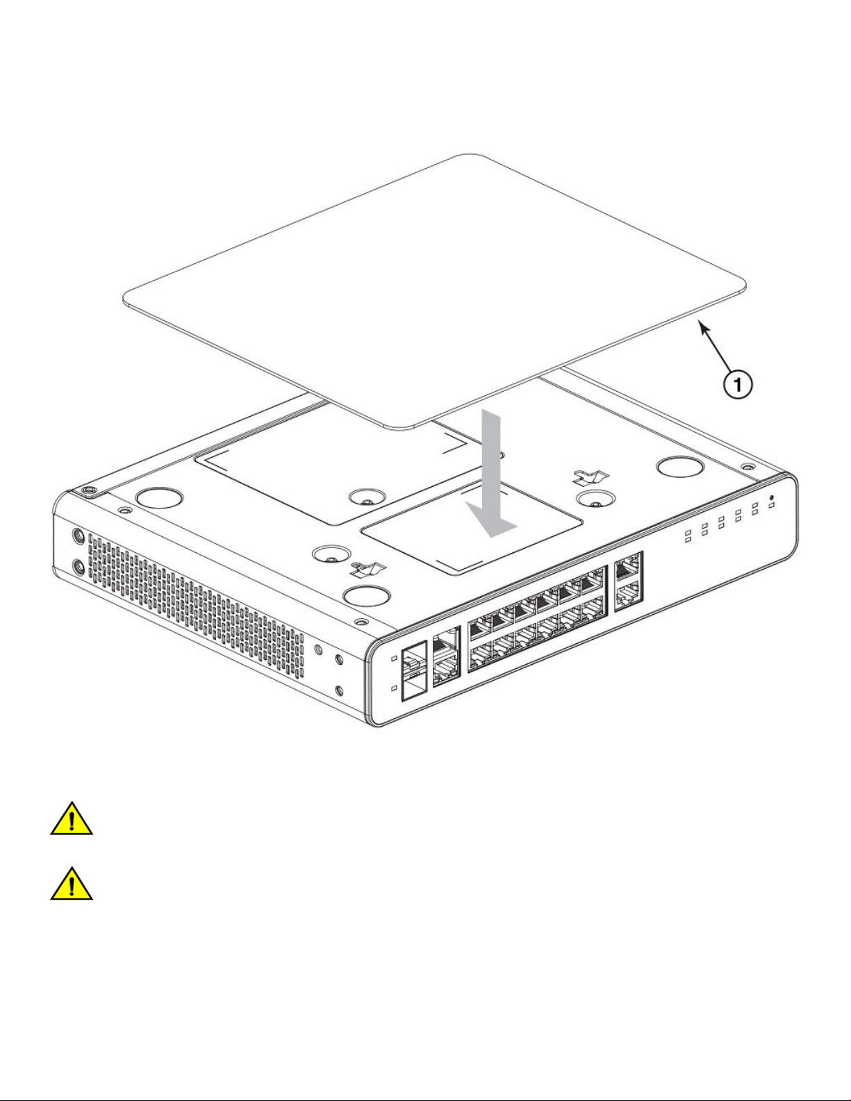
Mounting the Device
Mounting the compact device with a magnet
FIGURE 15 Attaching the logo side of the magnet sheet to the bottom panel of the compact device
Mounting the device on a metal surface or metal wall
CAUTION
Do not mount the device on a surface with the top panel facing downward. Mount the device only on a vertical metal surface with
the front panel port-side facing downward.
CAUTION
Ensure that the metal surface is flat and the texture is smooth to hold the device strongly. Check for other conditions that might
impede secure magnetic mount.
Complete the following steps to securely mount a compact device on a metal surface or metal wall:
1. Ensure that the magnet sheet is attached to the bottom panel of the device. Refer to Attaching the magnet sheet to the device on
page 31.
32 Part Number: 53-1004928-05
Ruckus ICX 7150 Switch Hardware Installation Guide
Page 33

Mounting the Device
Mounting the compact device with a magnet
2. Place the magnet sheet (with the logo side now attached to the bottom panel of the device) against the metal surface or metal
wall.
FIGURE 16 Mounting a compact device to a metal surface using the magnet mount
Ruckus ICX 7150 Switch Hardware Installation Guide
Part Number: 53-1004928-05 33
Page 34

Mounting the Device
Mounting the compact device with a magnet
FIGURE 17 A compact device mounted on a metal surface with ports down
Mounting the device under a metal desk
NOTE
Do not mount the device directly underneath a desktop surface with the top panel facing downward. Mount the device only on
the vertical metal surface of the desk with the front panel ports side facing downward.
Complete the following steps to securely mount a compact device under a metal desktop:
1. Ensure that the magnet sheet is attached to the bottom panel of the device. Refer to Attaching the magnet sheet to the device on
page 31.
34 Part Number: 53-1004928-05
Ruckus ICX 7150 Switch Hardware Installation Guide
Page 35

Mounting the Device
Mounting the compact device with a magnet
2. Place the bottom panel of the device with the magnet sheet attached under the metal desk, against the side of the device. Ensure
that the front panel (port side) of the device is facing downward.
FIGURE 18 Mounting a compact device underneath a metal desktop using the magnet mount
1. Magnet 2. Metal desk
Ruckus ICX 7150 Switch Hardware Installation Guide
Part Number: 53-1004928-05 35
Page 36
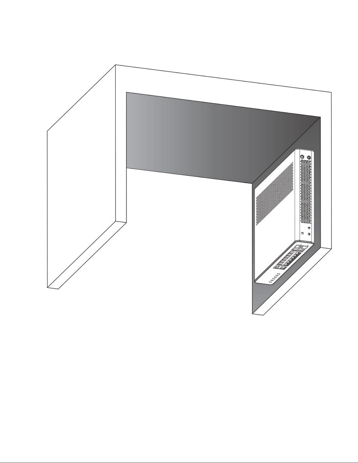
Mounting the Device
Mounting the compact device under a fixed surface
FIGURE 19 A compact device securely mounted underneath a metal desk with the port side facing down
Mounting the compact device under a fixed surface
Use the following items to mount the device under a fixed surface such as under a desk, or under a shelf.
• #2 Phillips screwdriver
• Hammer
• Drill
• Mounting anchors
• Wall / under desk mount kit (ICX7000-C12-WMK - short brackets) or two-post rack mount kit (ICX7000-C12-RMK - long brackets)
• Mounting screws
36 Part Number: 53-1004928-05
Ruckus ICX 7150 Switch Hardware Installation Guide
Page 37

Mounting the Device
Mounting the compact device under a fixed surface
DANGER
When mounting the device under a fixed surface, under a desk, or under a shelf, mount the device with the bottom panel down
and in a place where there is not much foot traffic. The fixed surface must be strong enough to withstand the weight of the device
such that the device or the surface does not fall down.
CAUTION
When mounting the device under a fixed surface, under a desk, or under a shelf, use the long brackets to provide adequate
ventilation and not exceed the operating temperature.
CAUTION
Do not install the device in an environment where the operating ambient temperature might exceed 35°C (95°F).
Ruckus ICX 7150 Switch Hardware Installation Guide
Part Number: 53-1004928-05 37
Page 38
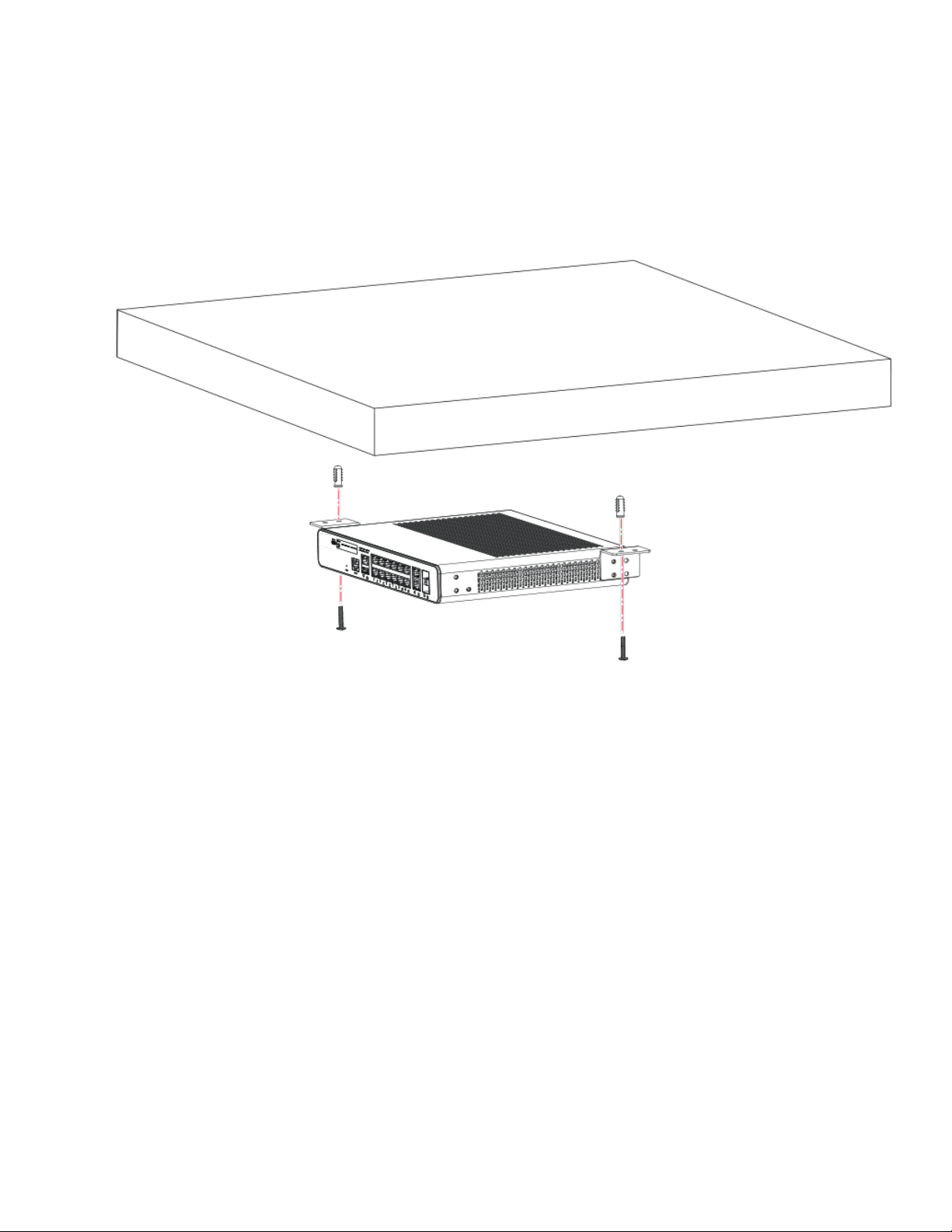
Mounting the Device
Mounting the compact device under a fixed surface
Complete the following steps to mount the device under a fixed surface.
1. Using a Phillips screwdriver, attach the mounting brackets to the diagonally opposite sides of the device using two #6-32 sinkhead screws on each side.
FIGURE 20 Mounting a compact device under a fixed surface with short brackets (ICX7000-C12-WMK)
38 Part Number: 53-1004928-05
Ruckus ICX 7150 Switch Hardware Installation Guide
Page 39

FIGURE 21 Mounting a compact device under a fixed surface with long brackets (ICX7000-C12-RMK)
Mounting the Device
Mounting the compact device directly on a wall
2. Drill two holes under the fixed surface or desk where you want to mount the device.
3. Hammer the mounting anchors into the two holes.
4. With the bottom panel of the device facing down, use the #2 Phillips screwdriver to secure the two mounting screws into the
mounting anchors.
Mounting the compact device directly on a wall
Use the following items to wall mount the device directly to a wall:
• #2 Phillips screwdriver
• Hammer
• Drill
• Wall mount anchors
• Wall mount screws
• Wall Mount Holes Location template
• Tape
NOTE
When mounting the device on a wall, mount the device with the port side down.
Ruckus ICX 7150 Switch Hardware Installation Guide
Part Number: 53-1004928-05 39
Page 40

Mounting the Device
Mounting the compact device directly on a wall
Complete the following steps to mount the device directly to a wall.
1. Use tape to place the Wall Mount Holes Location template against the wall, in the same position that you plan to place the device
against the wall. The Wall Mount Holes Location template serves as a guide to drilling the screws and wall-mount anchors into the
correct location on the wall in order to place the device in the desired location.
2. Using the Wall Mount Holes Location template as a guide, drill two holes in the wall where you want to mount the device.
3. Hammer the wall-mount anchors into the two holes.
40 Part Number: 53-1004928-05
Ruckus ICX 7150 Switch Hardware Installation Guide
Page 41

Mounting the Device
Mounting the compact device directly on a wall
4. Use the #2 Phillips screwdriver to secure the two wall-mount screws into the wall-mount anchors. Leave a gap of 4.0 to 4.5 mm
between the screw head and the wall.
FIGURE 22 Preparing to wall mount the device
1. Drilled holes in wall
2. Wall-mount anchors
3. Wall-mount screws
4. 4.0-4.5 mm space between screw head and wall
Ruckus ICX 7150 Switch Hardware Installation Guide
Part Number: 53-1004928-05 41
Page 42

Mounting the Device
Mounting the compact device directly on a wall
5. With the port side of the device facing down, aim the mounting holes on the bottom panel of the device towards the wallmounting screws on the wall and hang the device securely against the wall, so that the wall-mount screws are inserted into the
mounting holes.
FIGURE 23 Wall mounting a compact device - View of rear panel
42 Part Number: 53-1004928-05
Ruckus ICX 7150 Switch Hardware Installation Guide
Page 43
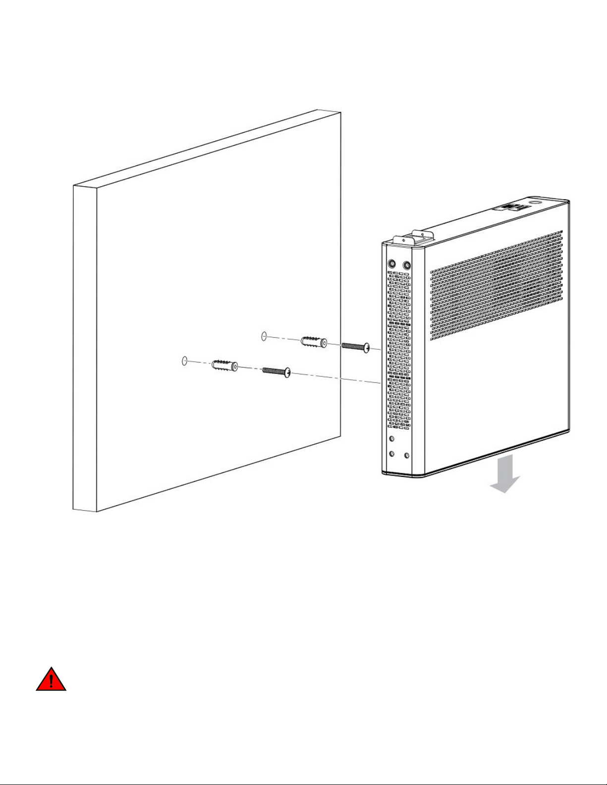
FIGURE 24 Wall mounting a compact device - View of the top panel
Mounting the Device
Mounting on a wall using the wall mount brackets
Mounting on a wall using the wall mount brackets
NOTE
You need a #2 Phillips screwdriver, a hammer, and a drill for wall mount installation.
NOTE
Mount the devices that have fans such that there is enough space for ventilation on the air-intake and air-exhaust sides to
maintain the ambient operating temperature.
DANGER
This equipment is suitable for mounting on concrete or other noncombustible surfaces only.
Ruckus ICX 7150 Switch Hardware Installation Guide
Part Number: 53-1004928-05 43
Page 44

Mounting the Device
Mounting on a wall using the wall mount brackets
NOTE
The hardware device illustrated in this procedure is only for reference and may not depict the actual device that you are installing.
Complete the following steps to mount the device to a wall.
1. Attach the four adhesive feet to the bottom of the device.
44 Part Number: 53-1004928-05
Ruckus ICX 7150 Switch Hardware Installation Guide
Page 45

Mounting the Device
Mounting on a wall using the wall mount brackets
2. Using a Phillips screwdriver, attach the wall mount brackets to the sides of the device using four #6-32 sink-head screws on each
side.
FIGURE 25 Attaching the wall mount brackets to a 24-port device
Ruckus ICX 7150 Switch Hardware Installation Guide
Part Number: 53-1004928-05 45
Page 46

Mounting the Device
Mounting on a wall using the wall mount brackets
FIGURE 26 Attaching the wall mount brackets to a 48-port device
3. Drill two holes on the wall where you want to mount the device.
4. Hammer two wall mount anchors into the holes on the wall.
46 Part Number: 53-1004928-05
Ruckus ICX 7150 Switch Hardware Installation Guide
Page 47

5. Use the two wall mount screws to fasten the device to the wall mount anchors.
FIGURE 27 Wall mounting a 24-port device with port-side up
Mounting the Device
Mounting on a wall using the wall mount brackets
1. Drilled holes
2. Wall mount anchors
Ruckus ICX 7150 Switch Hardware Installation Guide
Part Number: 53-1004928-05 47
3. Wall mount screws
Page 48

Mounting the Device
Mounting on a two-post rack
FIGURE 28 Wall mounting a 48-port device with port-side down
NOTE
Brocade recommends that you install the 24P, 48P, and 48PF models with the port-side down to maintain the ambient
temperature.
Mounting on a two-post rack
The devices use stationary mounting when mounted in a rack.
DANGER
Make sure the rack housing the device is adequately secured to prevent it from becoming unstable or falling over.
48 Part Number: 53-1004928-05
Ruckus ICX 7150 Switch Hardware Installation Guide
Page 49

Mounting the Device
Mounting on a two-post rack
CAUTION
Ensure that adequate ventilation and airflow is provided for the system. A 4.5 cm (1.77 in) clearance is recommended above and
below the device and 8 cm (3.15 in) clearance is recommended on each side.
NOTE
You need a #2 Phillips screwdriver for rack mount installation.
NOTE
The ICX 7150-C12P compact device requires the ICX7000-C12-RMK rack mount kit which is optionally orderable.
Complete the following steps to mount devices in a rack.
1. Remove the rack mounting kit from the shipping carton. The kit contains two L-shaped mounting brackets and six sink-head
screws.
Ruckus ICX 7150 Switch Hardware Installation Guide
Part Number: 53-1004928-05 49
Page 50

Mounting the Device
Mounting on a two-post rack
2. Using a Phillips screwdriver, attach the mounting brackets to the sides of the device using six sink-head screws.
FIGURE 29 Attaching the mounting brackets for a compact device
50 Part Number: 53-1004928-05
Ruckus ICX 7150 Switch Hardware Installation Guide
Page 51
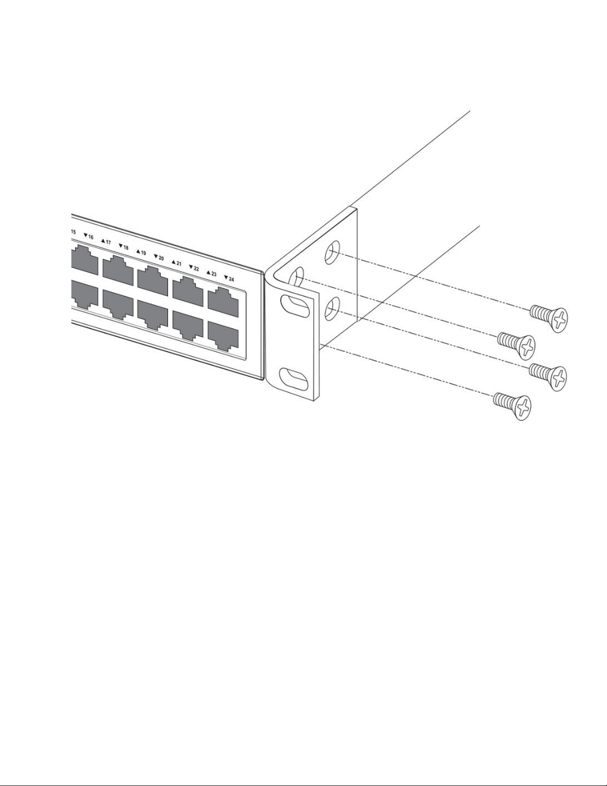
FIGURE 30 Attaching the rack mounting brackets for 24-port and 48-port devices
Mounting the Device
Mounting on a two-post rack
3. Remove the two-post rack kit from the shipping carton. The kit contains four rack-mounting screws and four cage nuts.
4. Insert the cage nuts in the two-post rack where you want to mount the device.
Ruckus ICX 7150 Switch Hardware Installation Guide
Part Number: 53-1004928-05 51
Page 52

Mounting the Device
Mounting on a two-post rack
5. Using a Phillips screwdriver, mount the device in a two-post rack using four rack-mounting screws.
FIGURE 31 Installing a compact device in a two-post rack
1. Rack-mounting screws 2. Cage nuts
52 Part Number: 53-1004928-05
Ruckus ICX 7150 Switch Hardware Installation Guide
Page 53
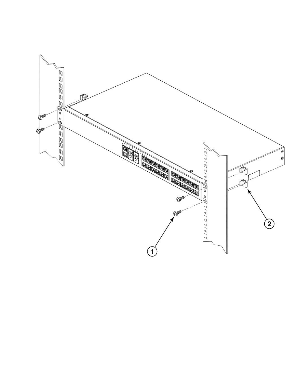
FIGURE 32 Installing a 24-port or 48-port device in a two-post rack
Mounting the Device
Installing the 1U, 1.5U, and 2U Universal Kit for Four Post Racks (XBR-R000295)
1. Rack-mounting screws
2. Cage nuts
6. If installing multiple devices, mount them in the rack, one below the other with the heaviest device at the bottom and lightest
device on the top.
Installing the 1U, 1.5U, and 2U Universal Kit for Four
Post Racks (XBR-R000295)
Use the following instructions to install a 1U, 1.5U, or 2U device in a 19-in. (48.3 cm) EIA rack using the 1U, 1.5U, and 2U Universal Kit for
Four Post Racks (XBR-R000295). Any updates to these instructions will be added to the hardware installation guide for your product.
Ruckus ICX 7150 Switch Hardware Installation Guide
Part Number: 53-1004928-05 53
Page 54

Mounting the Device
Time and items required
The device can be installed so that the port side is either flush with the front posts or recessed with the non-port side flush with the rear
posts. A recessed position allows a more gradual bend in the fiber-optic cables connected to the device and less interference in the aisle at
the front of the rack.
NOTE
Hardware devices illustrated in these procedures are only for reference and may not depict the device you are installing into the
rack.
Time and items required
Allow 15 to 30 minutes to complete this procedure. Note the following requirements to ensure correct installation and operation.
The following items are required to install the device using the 1U, 1.5U, and 2U Universal Kit for Four-Post Racks:
• #2 Phillips torque screwdriver
• 1/4-inch slotted-blade torque screwdriver
Parts list
The following parts are provided with the 1U, 1.5U, and 2U Universal Kit for Four Post Racks Installation (XBR-R000295).
54 Part Number: 53-1004928-05
Ruckus ICX 7150 Switch Hardware Installation Guide
Page 55

FIGURE 33 Rack kit parts
Mounting the Device
Flush-front mounting the device in the rack
1. Front brackets (2)
2. Bracket extensions (2)
3. Rear brackets, short (2)
4. Rear brackets, medium (2)
5. Rear brackets, long (2)
6. Screw, 8-32 x 5/16-in., panhead Phillips (8)
7. Screw, 8-32 x 5/16-in., flathead Phillips (16)
8. Screw, 6-32 x 1/4-in., panhead Phillips (8)
9. Screw, 10-32 x 5/8-in., panhead Phillips (8)
10. Retainer nut, 10-32 (8)
Ensure that the items listed and illustrated are included in the kit. Note that not all parts may be used with certain installations depending on
the device type.
CAUTION
Use the screws specified in the procedure. Using longer screws can damage the device.
Flush-front mounting the device in the rack
CAUTION
The device must be turned off and disconnected from the fabric during this procedure.
NOTE
Illustrations in these rack installation procedures are for reference only and may not show the actual device that you are installing.
Ruckus ICX 7150 Switch Hardware Installation Guide
Part Number: 53-1004928-05 55
Page 56

Mounting the Device
Flush-front mounting the device in the rack
Complete the following tasks to install the device in a four-post rack:
1. Attaching the front brackets on page 56
2. Attaching the bracket extensions to the device on page 57
3. Installing the device in the rack on page 58
4. Attaching the rear brackets to the extensions on page 59
5. Attaching the rear brackets to the rack posts on page 61
Attaching the front brackets
Complete the following steps to attach the front brackets to the device.
1. Position the right front bracket with the flat side against the right side of the device at the front of the device, as shown in Figure
34.
2. Insert four 8-32 x 5/16-in. flathead screws through the vertically aligned holes in the bracket and then into the holes on the side of
the device. Use the upper and lower screw holes, leaving the center holes empty.
3. Repeat Step 1 and Step 2 to attach the left front bracket to the left side of the device.
56 Part Number: 53-1004928-05
Ruckus ICX 7150 Switch Hardware Installation Guide
Page 57

4. Tighten all the 8-32 x 5/16-in. screws to a torque of 15 in-lb (17 cm-kg).
FIGURE 34 Attaching the front brackets
Mounting the Device
Flush-front mounting the device in the rack
1. Brocade device
2. Front brackets
3. Screws, 8-32 x 5/16-in., flathead Phillips
Attaching the bracket extensions to the device
Complete the following steps to attach the extension brackets to the device.
1. Position the right bracket extension along the side of the device as shown in Figure 35.
2. Insert four 8-32 x 5/16-in. flathead screws through the vertically aligned holes in the bracket extension and then into the holes on
the side of the device. Use the upper and lower screw holes, leaving the center holes empty.
3. Repeat step 1 and step 2 to attach the left bracket extension to the left side of the device.
Ruckus ICX 7150 Switch Hardware Installation Guide
Part Number: 53-1004928-05 57
Page 58

Mounting the Device
Flush-front mounting the device in the rack
4. Tighten all the 8-32 x 5/16-in. screws to a torque of 15 in-lb (17 cm-kg).
FIGURE 35 Attaching the bracket extensions to the device
1. Bracket extensions 2. Screws, 8-32 x 5/16-in., flathead Phillips
Installing the device in the rack
Complete the following steps to install the device in the rack.
1. Position the device in the rack, as shown in Figure 36, providing temporary support under the device until the rail kit is secured to
the rack.
2. Attach the right front bracket to the right front rack post using two 10-32 x 5/8-in. panhead screws and two retainer nuts. Use the
upper and lower holes in the bracket.
3. Attach the left front bracket to the left front rack post using two 10-32 x 5/8-in. panhead screws and two retainer nuts. Use the
upper and lower holes in the bracket.
58 Part Number: 53-1004928-05
Ruckus ICX 7150 Switch Hardware Installation Guide
Page 59

4. Tighten all the 10-32 x 5/8-in. screws to a torque of 25 in-lb (29 cm-kg).
FIGURE 36 Positioning the device in the rack
Mounting the Device
Flush-front mounting the device in the rack
1. Screws, 10-32 x 5/8-in., panhead Phillips 2. Retainer nuts, 10-32
Attaching the rear brackets to the extensions
Complete the following steps to attach the rear brackets to the extensions. There are short, medium, and long rear brackets that you can
use for this step. Choose the correct bracket for the depth of your rack.
1. Select the proper length rear bracket for your rack depth.
2. Slide the right rear bracket onto the right extension, as shown in Figure 37.
The short rear brackets are shown. Use the first and third vertical pairs of holes for the screws.
Refer to Figure 38 for the positioning of the medium or long brackets and screws.
3. Attach the brackets using four 6-32 x 1/4-in. panhead screws.
4. Repeat Step 2 and Step 3 to attach the left rear bracket to the left extension.
Ruckus ICX 7150 Switch Hardware Installation Guide
Part Number: 53-1004928-05 59
Page 60

Mounting the Device
Flush-front mounting the device in the rack
5. Adjust the brackets to the rack depth and tighten all the 6-32 x 1/4-in. screws to a torque of 9 in-lb (10 cm-kg).
FIGURE 37 Attaching the short rear brackets to the extensions
1. Rear brackets 2. Screws, 6-32 x 1/4-in., panhead Phillips
FIGURE 38 Attaching the medium or long rear brackets to the extensions
60 Part Number: 53-1004928-05
Ruckus ICX 7150 Switch Hardware Installation Guide
Page 61
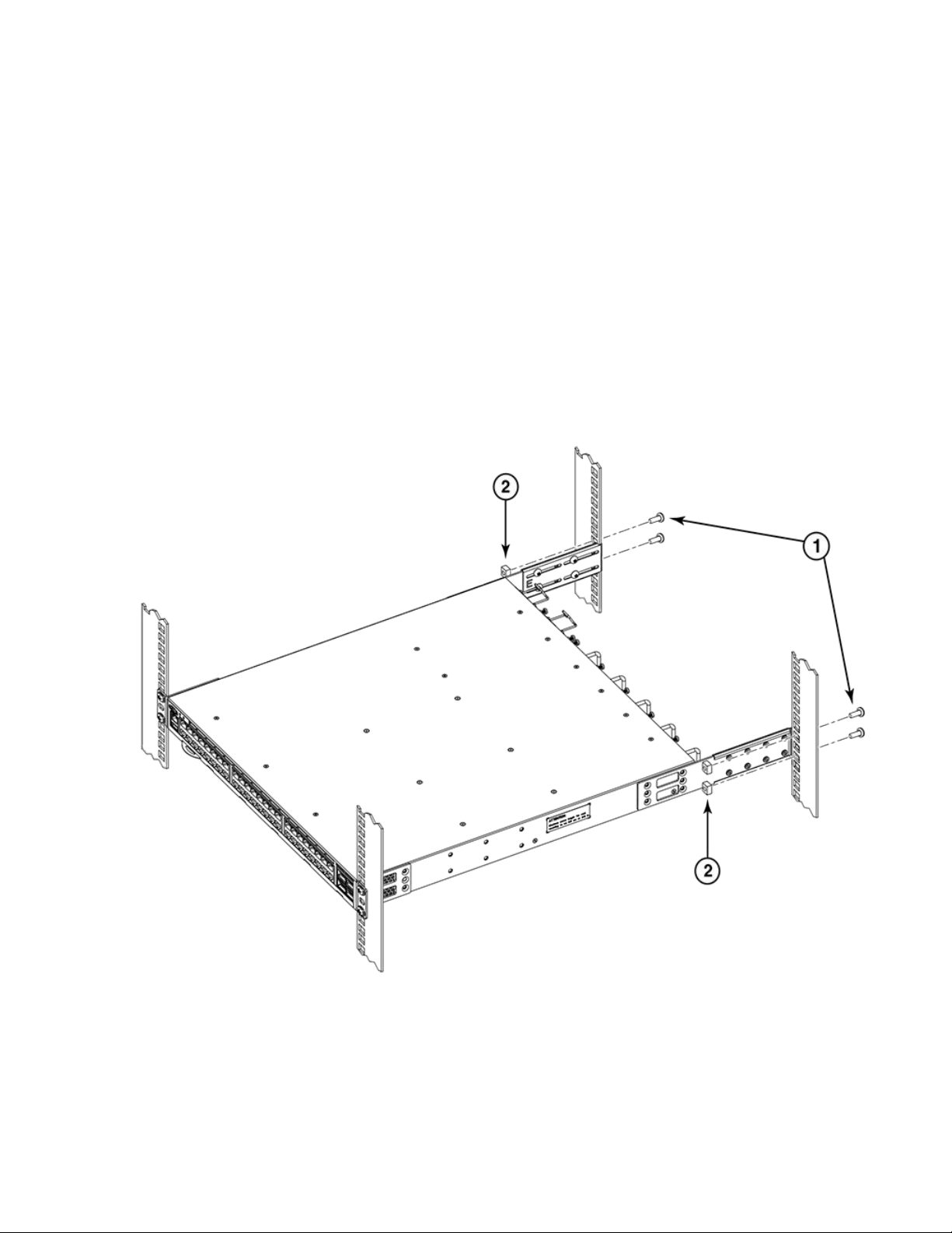
Mounting the Device
Flush-front mounting the device in the rack
1. Rear bracket, medium or long
2. Screws, 6-32 x 1/4-in., panhead Phillips
Attaching the rear brackets to the rack posts
Complete the following steps to attach the rear brackets to the rack posts.
1. Attach the right rear bracket to the right rear rack post using two 10-32 x 5/8-in. panhead screws and two retainer nuts, as shown
in Figure 39. Use the upper and lower holes in the bracket.
2. Attach the left rear bracket to the left rear rack post using two 10-32 x 5/8-in. panhead screws and two retainer nuts. Use the
upper and lower holes in the bracket.
3. Tighten all the 10-32 x 5/8-in. screws to a torque of 25 in-lb (29 cm-kg).
FIGURE 39 Attaching the rear brackets to the rack posts
1. Screws, 10-32 x 5/8-in., panhead Phillips 2. Retainer nuts, 10-32
Ruckus ICX 7150 Switch Hardware Installation Guide
Part Number: 53-1004928-05 61
Page 62

Mounting the Device
Flush-rear (recessed) mounting the device in the rack
Flush-rear (recessed) mounting the device in the rack
The flush-rear (recessed) mounting is similar to the flush-front mounting except that the brackets are reversed on the device.
CAUTION
The device must be turned off and disconnected from the fabric during this procedure.
NOTE
Illustrations used in these rack installation procedures are for reference only and may not show the actual device that you are
installing.
Complete the following tasks to install the device in a four-post rack:
1. Attaching the front brackets to the rear of the device on page 62
2. Attaching the bracket extensions to the front of the device on page 63
3. Installing the device in the rack on page 64
4. Attaching the rear brackets to the bracket extensions at the front of the device on page 65
5. Attaching the rear brackets to the front rack posts on page 67
Attaching the front brackets to the rear of the device
NOTE
In this installation, the brackets are named as listed in the parts list even though the installation of the brackets is reversed from
the flush-front installation.
Complete the following steps to attach the front brackets to the rear of the device.
1. Position the right front bracket with the flat side against the right rear side of the device, as shown in Figure 40.
2. Insert four 8-32 x 5/16-in. flathead screws through the vertically aligned holes in the bracket and then into the holes on the side of
the device. Use the upper and lower screw holes, leaving the center holes empty.
3. Repeat Step 1 and Step 2 to attach the left front bracket to the left rear side of the device.
62 Part Number: 53-1004928-05
Ruckus ICX 7150 Switch Hardware Installation Guide
Page 63

4. Tighten all the 8-32 x 5/16-in. screws to a torque of 15 in-lb (17 cm-kg).
FIGURE 40 Attaching the front brackets to the rear of the device
Mounting the Device
Flush-rear (recessed) mounting the device in the rack
1. Brocade device
2. Front brackets
3. Screws, 8-32 x 5/16-in., flathead Phillips
Attaching the bracket extensions to the front of the device
Complete the following steps to attach the bracket extensions to the front of the device.
1. Position the right bracket extension along the side of the device as shown in Figure 41.
2. Insert four 8-32 x 5/16-in. flathead screws through the vertically aligned holes in the bracket extension and then into the holes on
the side of the device. Use the upper and lower screw holes, leaving the center holes empty.
3. Repeat step 1 and step 2 to attach the left front bracket extension to the left side of the device.
Ruckus ICX 7150 Switch Hardware Installation Guide
Part Number: 53-1004928-05 63
Page 64

Mounting the Device
Flush-rear (recessed) mounting the device in the rack
4. Tighten all the 8-32 x 5/16-in. screws to a torque of 15 in-lb (17 cm-kg).
FIGURE 41 Attaching the bracket extensions to the device
1. Bracket extensions 2. Screws, 8-32 x 5/16-in., flathead Phillips
Installing the device in the rack
Complete the following steps to install the device in the rack.
1. Position the device in the rack, as shown in Figure 42, providing temporary support under the device until the rail kit is secured to
the rack.
2. Attach the right front bracket to the right rear rack post using two 10-32 x 5/8-in. panhead screws and two retainer nuts. Use the
upper and lower holes in the bracket.
3. Attach the left front bracket to the left rear rack post using two 10-32 x 5/8-in. panhead screws and two retainer nuts. Use the
upper and lower holes in the bracket.
64 Part Number: 53-1004928-05
Ruckus ICX 7150 Switch Hardware Installation Guide
Page 65

4. Tighten all the 10-32 x 5/8-in. screws to a torque of 25 in-lb (29 cm-kg).
FIGURE 42 Positioning the device in the rack
Mounting the Device
Flush-rear (recessed) mounting the device in the rack
1. Screws, 10-32 x 5/8-in., panhead Phillips 2. Retainer nuts, 10-32
Attaching the rear brackets to the bracket extensions at the front of the device
Complete the following steps to attach the rear brackets to the bracket extensions. There are short, medium, and long front brackets that
you can use for this step.
1. Select the proper length rear bracket for your rack depth.
2. Slide the right rear bracket onto the right extension, as shown in Figure 43.
The short rear brackets are shown. Use the first and third vertical pairs of holes for the screws.
Refer to Figure 44 for the positioning of the medium or long brackets and screws.
3. Attach the brackets using four 6-32 x 1/4-in. panhead screws.
4. Repeat Step 2 and Step 3 to attach the left rear bracket to the left extension.
Ruckus ICX 7150 Switch Hardware Installation Guide
Part Number: 53-1004928-05 65
Page 66

Mounting the Device
Flush-rear (recessed) mounting the device in the rack
5. Adjust the brackets to the rack depth and tighten all the 6-32 x 1/4-in. screws to a torque of 9 in-lb (10 cm-kg).
FIGURE 43 Attaching the short rear brackets to the extensions at the front of the device
1. Rear brackets, short 2. Screws, 6-32 x 1/4-in., panhead Phillips
66 Part Number: 53-1004928-05
Ruckus ICX 7150 Switch Hardware Installation Guide
Page 67

FIGURE 44 Attaching the medium or long rear brackets to the extensions
1. Rear bracket, medium or long 2. Screws, 6-32 x 1/4-in., panhead Phillips
Mounting the Device
Flush-rear (recessed) mounting the device in the rack
Attaching the rear brackets to the front rack posts
Complete the following steps to attach the rear brackets to the front rack posts.
1. Attach the right rear bracket to the right front rack post using two 10-32 x 5/8-in. screws and two retainer nuts, as shown in Figure
45. Use the upper and lower holes in the bracket.
2. Attach the left rear bracket to the left front rack post using two 10-32 x 5/8-in. screws and two retainer nuts. Use the upper and
lower holes in the bracket.
Ruckus ICX 7150 Switch Hardware Installation Guide
Part Number: 53-1004928-05 67
Page 68
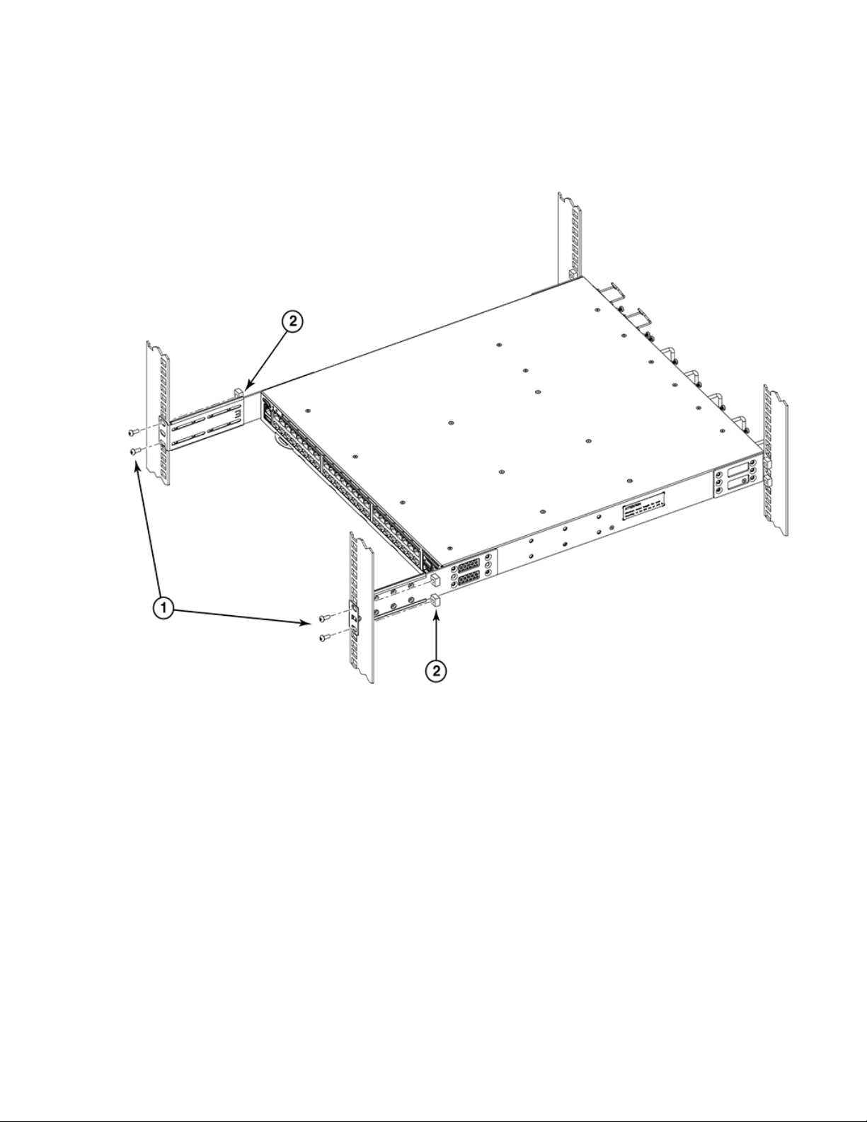
Mounting the Device
Flush-rear (recessed) mounting the device in the rack
3. Tighten all the 10-32 x 5/8-in. screws to a torque of 25 in-lb (29 cm-kg).
FIGURE 45 Attaching the rear brackets to the front rack posts
1. Screws, 10-32 x 5/8-in., panhead Phillips 2. Retainer nuts, 10-32
68 Part Number: 53-1004928-05
Ruckus ICX 7150 Switch Hardware Installation Guide
Page 69

Connecting ICX 7150 Devices in a Stack
• Stacking configuration requirements........................................................................................................................69
• ICX 7150 stacking ports.......................................................................................................................................... 69
• ICX 7150 stacking topologies..................................................................................................................................71
Stacking configuration requirements
Before configuring a traditional stack using the CLI, physically connect the devices with stacking cables. For more information on
configuring a stack, refer to the
ICX 7150 stacking ports
Depending on the model, up to eight SFP+ ports on the front panel of the ICX 7150 device support stacking. The ports can also be used as
uplink (data) ports. The following figures show the location and numbering for stacking ports. The numbering for the ports is in three-tuple
format (x/y/z) and refers to StackID/Slot/Port.
ICX 7150-C12P devices have two stacking ports on the front panel as shown in the following figure.
FIGURE 46 ICX 7150-C12P stacking ports
FastIron Stacking Configuration Guide
.
ICX 7150-24 and ICX 7150-24P devices have four stacking ports on the front panel as shown in the following figure.
Ruckus ICX 7150 Switch Hardware Installation Guide
Part Number: 53-1004928-05 69
Page 70

Connecting ICX 7150 Devices in a Stack
ICX 7150 stacking ports
FIGURE 47 ICX 7150 stacking port location on 24-port and some 48-port models
ICX 7150-48, ICX 7150-48P, and ICX 7150-48PF devices have four stacking ports in the same location on the front panel as ICX 7150 24port models.
The exception among 48-port models is the ICX 7150-48PZ, which has eight SPF+ ports on the front panel as shown in the following
figure. Four of these ports, ports 1/2/1 through 1/2/4, can be used as stacking or data uplink ports. The remaining four, 1/2/5 through
1/2/8, can be used only as data uplink ports.
FIGURE 48 ICX 7150-48ZP stacking ports
70 Part Number: 53-1004928-05
Ruckus ICX 7150 Switch Hardware Installation Guide
Page 71

Connecting ICX 7150 Devices in a Stack
ICX 7150 stacking topologies
ICX 7150 stacking topologies
Both linear and ring topologies are supported in a traditional stack. In a linear stack topology, a connection between each switch carries
two-way communications across the stack. The physical connection between the devices can use one port (stacked-port) or two ports
(stacked-trunk) per trunk.
In ring stack topology, an extra connection between the logical first and last devices forms a "ring" or "closed-loop." The closed-loop
connection provides a redundant path for the stack link, so if one link fails, stack communications can be maintained. You can connect
stacking units using one port per trunk or both ports in a trunk. For maximum bandwidth and link redundancy, use both ports per trunk.
Linear and ring topologies are depicted for different ICX 7150 models in the following figures.
NOTE
Port numbers shown are specific to each physical unit; that is, the unit ID is 1, in the three-tuple StackID/slot/port notation.
Assuming the stack in the following figure is numbered from the bottom when it is configured, the connected stacking port for the
bottom stack (stack unit 1) would be identified as port 1/3/2, and the connected port in the middle stack unit (stack unit 2) would
be identified as 2/3/1. Port 2/3/2 in the middle stack unit would be shown as connecting to port 3/3/1 in the top unit (stack unit
3).
NOTE
The Secure-setup utility used to discover and configure the stack assigns each unit a different stack ID. You can override the
automatic selection if you choose. Refer to the
FastIron Stacking Configuration Guide
for more information.
The following figures show examples of supported stacking topologies for the ICX 7150-C12P.
FIGURE 49 ICX 7150-C12P linear stack
Ruckus ICX 7150 Switch Hardware Installation Guide
Part Number: 53-1004928-05 71
Page 72

Connecting ICX 7150 Devices in a Stack
ICX 7150 stacking topologies
FIGURE 50 ICX 7150-C12P ring topology
The following figures show examples of supported topologies for ICX 7150 24-port models.
FIGURE 51 ICX 7150 24-port model, linear stack
72 Part Number: 53-1004928-05
Ruckus ICX 7150 Switch Hardware Installation Guide
Page 73

FIGURE 52 ICX 7150 24-port model, ring stack
Connecting ICX 7150 Devices in a Stack
ICX 7150 stacking topologies
The following figures show examples of supported topologies for the ICX 7150-48ZP.
FIGURE 53 ICX7150-48ZP linear stack
Ruckus ICX 7150 Switch Hardware Installation Guide
Part Number: 53-1004928-05 73
Page 74
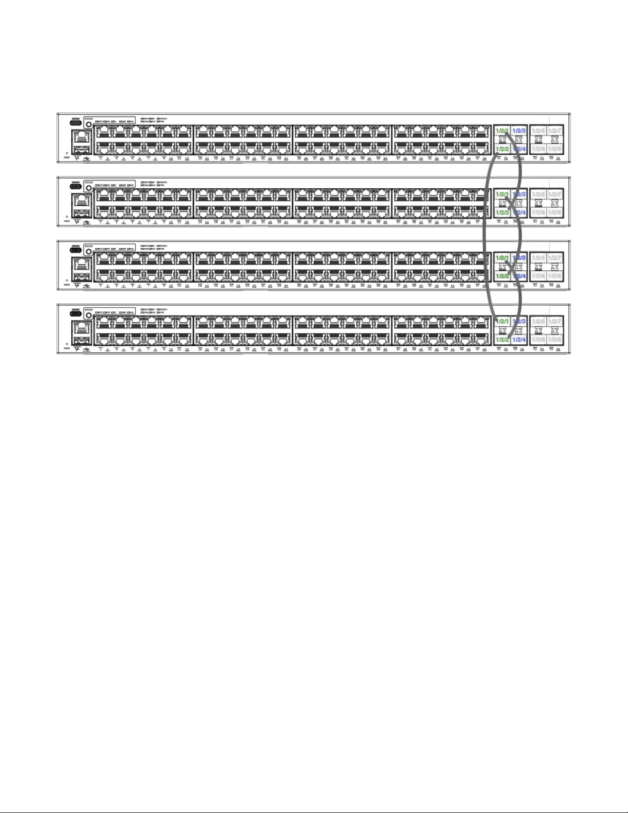
Connecting ICX 7150 Devices in a Stack
ICX 7150 stacking topologies
FIGURE 54 ICX 7150-48ZP ring stack
74 Part Number: 53-1004928-05
Ruckus ICX 7150 Switch Hardware Installation Guide
Page 75

Initial Setup and Verification
• Items required......................................................................................................................................................... 75
• Providing power to the device................................................................................................................................. 75
• Establishing a first-time connection to the console port........................................................................................... 76
• Configuring an IP address for the device................................................................................................................. 79
• Customizing the host name and chassis name .......................................................................................................79
• Setting the date and time........................................................................................................................................ 80
• Establishing a connection to the out-of-band management port..............................................................................80
• Getting in-band access........................................................................................................................................... 81
• Verifying the correct operation.................................................................................................................................81
• Backing up the running configuration...................................................................................................................... 81
Items required
The following items are required for initial setup and verification of the device:
• The device, mounted and installed with the required power supply, fan assemblies, transceivers, and cables
• A workstation computer with a terminal emulator application installed, such as HyperTerminal for Windows
• An unused IP address with corresponding subnet mask and gateway address
• An USB console cable with Type-C connector (Type-C USB cable not included with the device)
• A serial console cable with an RJ-45 connector (RJ-45 console cable not included with the device)
• An Ethernet cable
• Access to a TFTP server or USB removable media for backing up (uploading) or downloading the device configuration (optional)
Providing power to the device
Perform the following steps to provide power to the device.
1. Remove the power cord and the power cord retainer clip from the shipping carton container.
2. Install the power cord retainer clip to the power supply inlet on the device.
3. Connect the power cord to the power supply inlet on the device. Ensure that the power cords have a minimum service loop of 6
inches available and are routed properly to avoid stress.
4. Insert the power cord plug to power sources on separate circuits if there is more than one power cord for a single device in order
to protect against power failure.
5. If applicable, power on the power sources by flipping the switches to the on position. The SYST LED displays amber until poweron self-test (POST) is complete and then starts blinking green until the device is completely up. The device usually requires several
minutes to boot and complete POST.
NOTE
Power is supplied to the device as soon as the first power supply is connected and turned on. If the power indicator
does not turn on when the power cord is plugged in, you may have a problem with the power outlet, power cord, or
internal power supply.
Ruckus ICX 7150 Switch Hardware Installation Guide
Part Number: 53-1004928-05 75
Page 76

Initial Setup and Verification
Establishing a first-time connection to the console port
6. After POST is complete, verify that the switch power and switch status LEDs are green.
NOTE
Power Supply LED should always display solid green to ensure a working power supply. If the LED is amber, it indicates
a faulty PSU.
For more information about how to interpret POST, BOOT, and diagnostics tests, refer to Monitoring the Device on page 91.
Establishing a first-time connection to the console
port
You can use either the USB Type-C console port or the RJ-45 serial console port to establish the first time connection to the device. The
console port allows you to configure and manage the device using a third-party terminal emulation application from a workstation that is
directly connected to the port using a standard USB Type-C cable or RJ-45 serial cable. Perform the following steps to log in to the device
for the first time through the console connection.
1. Do one of the following:
• Connect a standard USB cable to the USB Type-C console connector on the device and to a USB port on the workstation.
To connect the USB Type-C console port on the device to a USB port on the workstation, you need a standard USB cable
that has a USB Type-C connector on one end and a USB connector on the other end that matches the USB port on your
workstation.
• Connect a standard RJ-45 cable to the RJ-45 serial console connector on the device and to a USB port on the workstation.
To connect the RJ-45 serial console port on the device to a USB port on the workstation, you need a standard RJ-45 cable
that has a RJ-45 connector on one end and a USB connector on the other end that matches the USB port on your
workstation.
2. Allow the workstation to automatically discover and configure the newly found USB device.
NOTE
If the workstation is unable to automatically discover and configure the newly found USB device, you can manually
download the necessary device drivers for Windows, MacOS, and Linux from the following website: http://
my.brocade.com
76 Part Number: 53-1004928-05
Ruckus ICX 7150 Switch Hardware Installation Guide
Page 77

Initial Setup and Verification
Establishing a first-time connection to the console port
3. Open a terminal emulator application such as HyperTerminal on a Windows PC, or TERM, TIP, or Kermit in a UNIX environment,
and configure the sessions parameters as follows:
• In a Windows environment, use the following values:
Parameter Value
Baud: Bits per second 9600
Data bits 8
Parity None
Stop bits 1
Flow control None
NOTE
Flow control is not supported on the console connection when attached to a remote terminal and must be disabled
on the customer-side remote terminal server in addition to the host-side clients.
• In a UNIX environment using TIP, enter the following string at the prompt:
tip /dev/ttyb -9600.
If ttyb is already in use, use ttya instead and enter the following string at the prompt:
tip /dev/ttya -9600
4. When the terminal emulator application stops reporting information, press Enter to display the device prompt.
Depending on the device you purchased, and the code (Layer 2 or Layer 3) loaded on your system, the device prompt is displayed
accordingly.
device>
When the device prompt is displayed, you are connected to the device. You can customize the prompt by changing the device
name. If you do not see this prompt, make sure the cable is securely connected to your workstation and to the device and check
the settings in your terminal emulation program. In addition to the previously configured session settings, make sure the terminal
emulation session is running on the same serial port you attached to the device.
The device CLI prompt has the following access levels:
• User EXEC: This is the level you enter when you first start a CLI session. At this level, you can view some system information
but you cannot configure system or port parameters.
• Privileged EXEC: This level is also called the Enable level and can be secured by a password. You can perform tasks such as
managing files on the flash module, saving the system configuration to flash, and clearing caches at this level.
• CONFIG: The configuration level. This level allows you to configure the system IP address and configure switching and routing
features. To access the CONFIG mode, you must already be logged in to the privileged EXEC level.
Ruckus ICX 7150 Switch Hardware Installation Guide
Part Number: 53-1004928-05 77
Page 78

Initial Setup and
Verification
Establishing a first-time connection to the console port
5. At the opening CLI prompt, enter the following command to change to the Privileged EXEC mode:
device> enable
device#
By default, the CLI is not protected by passwords. To secure CLI access, Brocade strongly recommends assigning passwords.
You can set the following levels of passwords:
• Super User: Allows complete read-and-write access to the system. This is generally for system administrators and is the only
password level that allows you to configure other passwords.
NOTE
You must set a Super User password before you can set other types of passwords. You can also assign other
passwords using Brocade Network Advisor after an enable password has been configured for a Super User on the
device using the CLI.
• Port Configuration: Allows read-and-write access to specific ports but not for global (system-wide) parameters.
• Read-Only: Allows access to the privileged EXEC mode and CONFIG mode but only with read access.
NOTE
Passwords can be up to 32 characters long. They must begin with an alphabetic character. They can include
numeric characters, the period (.), and the underscore (_) only. Passwords are case-sensitive, and they are not
displayed when you enter them on the command line.
6. Access the configuration mode of the CLI by entering the following command:
device# configure terminal
device(config)#
7. Enter the following command to set the Super User password:
device(config)# enable super-user-password joe
NOTE
Make sure to write down the new passwords and keep the information in a secure location.
8. Enter the following commands to set the port configuration and read-only passwords.
device(config)# enable port-config-password john
device(config)# enable read-only-password sam
Recovering from a lost password
If a password has been configured for the device but the password has been lost, you can regain Super User access to the device using
the following procedure.
Recovery from a lost password requires direct access to the serial port and a system reset.
1. Start a CLI session over the serial interface to the Brocade device.
2. Reboot the device.
3. While the system is booting, before the initial system prompt appears, enter b to enter the boot monitor mode.
4. Enter no password. (You cannot abbreviate this command.)
5. Enter boot. This command causes the device to bypass the system password check.
6. After the console prompt reappears, assign a new password.
78 Part Number: 53-1004928-05
Ruckus ICX 7150 Switch Hardware Installation Guide
Page 79

Initial Setup and
Customizing the host name and chassis name
Verification
Configuring an IP address for the device
You must configure at least one IP address using the serial connection to the CLI before you can manage the device using the other
management interfaces. You can use the classical IP network masks (Class A, B, and C subnet masks, and so on) or Classless Interdomain
Routing (CIDR) network prefix masks.
• To enter a classical IP network mask, enter the mask in IP address format. For example, enter "10.157.22.99 255.255.255.0" for
an IP address with a Class C subnet mask.
• To enter a prefix number for a network mask, enter a forward slash (/) and the number of bits in the mask immediately after the IP
address. For example, enter "10.157.22.99/24" for an IP address that has a network mask with 24 significant ("mask") bits.
1. At the opening CLI prompt, enter the following commands.
device> enable
device# erase startup-config
device# configure terminal
NOTE
Use the erase startup-cong command only for new systems. If you enter this command on a system you have already
configured, the command erases the configuration. If you accidentally erase the configuration on a configured system,
enter the write memory command to save the running configuration to the startup-config file.
2. Enter the following commands to assign an IP address for a device running Layer 2 software.
device(config)# ip address 10.22.3.44 255.255.255.0
device(config)# ip default-gateway 10.22.3.1
device(config)# write memory
NOTE
You do not need to assign a default gateway address for single subnet networks.
Enter the following commands to add an IP address and mask to a router port on a device running Layer 3 software.
device(config)# interface ethernet 1
device(config)# ip address 10.22.3.44 255.255.255.0
device(config)# write memory
NOTE
Before attaching any equipment to a device running Layer 3 software, you must assign an interface IP address to the
subnet on which the device will be located. You must use the serial connection to assign the first IP address. For
subsequent addresses, you can use the CLI through Telnet.
3. Assign an interface IP address to the out-of-band management Ethernet port.
device(config)# interface management 1
device(config)# ip address 10.22.3.45 255.255.255.0
device(config)# write memory
The management port number is always 1.
Customizing the host name and chassis name
Changing the host name, contact, and location is important for distinguishing and identifying the device uniquely and for accurate tracking
of logs and errors. The messages that appear in the log are labeled with the chassis name, which makes tracking the errors much easier.
Specify an easily understandable and meaningful host name and chassis name.
Ruckus ICX 7150 Switch Hardware Installation Guide
Part Number: 53-1004928-05 79
Page 80

Initial Setup and Verification
Setting the date and time
Perform the following steps to change the host name and then the chassis name.
1. Customize the host name, contact, and location using the following commands. When you configure a host name, the name
replaces the default system name in the device CLI prompt.
device(config)# hostname sj_device1
sj_device1(config)# snmp-server contact Support Services
sj_device1(config)# snmp-server location San Jose
sj_device1(config)# end
sj_device1# write memory
The name, contact, and location each can be up to 255 alphanumeric characters. The text strings can contain blanks. The SNMP
text strings do not require quotation marks when they contain blanks but the host name does.
2. Change the chassis name by using the chassis name command.
device(config)# chassis name SJ001
sj_device1(config)# end
sj_device1# write memory
The chassis name command does not change the device CLI prompt. Instead, the command assigns an administrative ID to the
device.
Setting the date and time
Use the following command to set the current date and time for the device.
device# clock set
hh:mm:ss Current Time
device# clock set 10:05:45
mm-dd-yy/yyyy Current Date
device# clock set 10:05:45 12-01-16
Establishing a connection to the out-of-band management port
The out-of-band management interface is an RJ-45 Ethernet port that allows you to access, configure, and manage the device from the
network. Perform the following steps to establish a connection to the device using the out-of-band Ethernet management port.
1. Remove the plug from the RJ-45 management port.
2. Connect an Ethernet cable to the device RJ-45 management port and to the workstation or to an Ethernet network containing the
workstation.
NOTE
At this point, the device can be accessed remotely using the CLI or Brocade Network Advisor. Ensure that the device is
not being modified from any other connections. The Ethernet management port also supports auto-MDI and auto-MDIX.
80 Part Number: 53-1004928-05
Ruckus ICX 7150 Switch Hardware Installation Guide
Page 81

Initial Setup and Verification
Backing up the running configuration
Getting in-band access
You can access the management agent in the device from anywhere within the attached network using Telnet or other network
management software. However, you must first configure the device with a valid IP address, subnet mask, and default gateway. If you have
trouble establishing a link to the management agent, check to see if you have a valid network connection. Then verify that you entered the
correct IP address. Also, be sure the port through which you are connecting to the device has not been disabled. If it has not been
disabled, then check the network cabling that runs between your remote location and the device.
Verifying the correct operation
Check the LEDs to verify operation of functional parts. The following commands can be useful to establish an operational baseline for the
device. Refer to the
show chassis
•
show version
•
show cpu
•
show ash
•
show les
•
show run
•
show boot-preference
•
show conguration
•
show running-cong
•
show logging
•
Ruckus FastIron Command Reference
for more information on these commands.
Backing up the running configuration
Use the write memory command to replace the startup configuration with the running configuration every time you make changes to the
device configuration. To back up the device configuration to an external TFTP server, use the copy running-cong tftp command.
device# copy running-config tftp 2001:DB8:e0ff:7837::3 newrun.cfg
This command example copies the running configuration to a TFTP server with the IPv6 address of 2001:DB8:e0ff:7837::3 and names the
file on the TFTP server newrun.cfg.
Ruckus ICX 7150 Switch Hardware Installation Guide
Part Number: 53-1004928-05 81
Page 82

82 Part Number: 53-1004928-05
Ruckus ICX 7150 Switch Hardware Installation Guide
Page 83

Installing Transceivers and Cables
• Time and items required..........................................................................................................................................83
• Precautions specific to transceivers and cables.......................................................................................................83
• Managing cables..................................................................................................................................................... 84
• Installing the Ethernet RJ-45 cables.........................................................................................................................84
• Cleaning the fiber-optic connectors.........................................................................................................................86
• Installing a new fiber-optic transceiver..................................................................................................................... 86
• Cabling a fiber-optic transceiver...............................................................................................................................87
• Replacing a fiber-optic transceiver...........................................................................................................................88
Time and items required
The installation or replacement procedure for one transceiver takes less than five minutes. Ensure that the following items are available:
• Required number of compatible power cables
• Required number of supported Ruckus-branded transceivers
Refer to the Brocade optics family datasheet for the list of supported transceivers and cables.
• Required number of compatible Ethernet (RJ-45) and fiber-optic cables
• Optical transceiver extraction tool (for 10-Gbps transceiver only)
NOTE
Most Ruckus switches come with a transceiver extraction tool and holster. The extraction tool is designed to remove
transceivers from modules where the space is limited.
FIGURE 55 Optical transceiver extraction tool
Precautions specific to transceivers and cables
DANGER
The procedures in this manual are for qualified service personnel.
Ruckus ICX 7150 Switch Hardware Installation Guide
Part Number: 53-1004928-05 83
Page 84

Installing Transceivers and Cables
Managing cables
DANGER
For safety reasons, the ESD wrist strap should contain a series 1 megaohm resistor.
DANGER
All fiber-optic interfaces use Class 1 lasers.
DANGER
Use only optical transceivers that are qualified by Brocade Communications Systems, Inc. and comply with the FDA Class 1
radiation performance requirements defined in 21 CFR Subchapter I, and with IEC 60825 and EN60825. Optical products that do
not comply with these standards might emit light that is hazardous to the eyes.
CAUTION
Before plugging a cable into any port, be sure to discharge the voltage stored on the cable by touching the electrical contacts to
ground surface.
Managing cables
Cables can be organized and managed in a variety of ways, for example, using cable channels on the sides of the rack or patch panels to
minimize cable management. Follow these recommendations:
NOTE
You should not use tie wraps with optical cables because they are easily overtightened and can damage the optic fibers.
CAUTION
Before plugging a cable into any port, be sure to discharge the voltage stored on the cable by touching the electrical contacts to
ground surface.
• The minimum bend radius for a 50 micron cable is 2 inches under full tensile load and 1.2 inches with no tensile load.
• Plan for rack space required for cable management before installing the switch.
• Leave at least 1 m (3.28 ft) of slack for each port cable. This provides room to remove and replace the switch, allows for
inadvertent movement of the rack, and helps prevent the cables from being bent to less than the minimum bend radius.
• If you are using Brocade ISL Trunking, consider grouping cables by trunking groups. The cables used in trunking groups must
meet specific requirements, as described in the Brocade optics family datasheet.
• For easier maintenance, label the fiber-optic cables and record the devices to which they are connected.
• Keep LEDs visible by routing port cables and other cables away from the LEDs.
• Use hook and loop style straps to secure and organize fiber-optic cables.
Installing the Ethernet RJ-45 cables
The device supports connection to other vendors’ routers, switches, hubs, as well as other Ruckus devices through the appropriate ports,
transceivers, and cables.
• For copper connections to Ethernet hubs, a 10/100Base-TX or 1000Base-T switch, or another Brocade device, a crossover cable
is required as shown in the following figure. If the hub is equipped with an uplink port, it requires a straight-through cable instead of
a crossover cable. The 802.3ab standard (automatic MDI or MDIX detection) calls for automatic negotiation of the connection
between two 1000Base-T ports. In this case, a straight-through cable may work just as well as a crossover cable.
84 Part Number: 53-1004928-05
Ruckus ICX 7150 Switch Hardware Installation Guide
Page 85

FIGURE 56 UTP crossover cable
Installing Transceivers and Cables
Installing the Ethernet RJ-45 cables
• Straight-through UTP cabling is required for direct UTP attachment to workstations, servers, or routers using network interface
cards (NICs). Fiber-optic cabling is required for direct attachment to Gigabit NICs or switches and routers through fiber ports.
FIGURE 57 Straight-through cable
• All 10/100 and 1000 Mbps Ethernet copper ports on the devices support automatic Media Dependent Interface (auto-MDI) or
automatic Media Dependent Interface Crossover (auto-MDIX) detection. Auto-MDI or auto-MDIX is enabled on all 10/100 and
1000 Mbps copper ports by default. For each port, you can disable auto-MDI or auto-MDIX, designate the port as an MDI port, or
designate the port as an MDIX port.
Ruckus ICX 7150 Switch Hardware Installation Guide
Part Number: 53-1004928-05 85
Page 86

Installing Transceivers and Cables
Cleaning the fiber-optic connectors
Cleaning the fiber-optic connectors
To avoid problems with the connection between the fiber-optic transceiver (SFP+ or QSFP) and the fiber cable connectors, Brocade
strongly recommends cleaning both connectors each time you disconnect and reconnect them. Dust can accumulate on the connectors
and cause problems such as reducing the optic launch power.
To clean the fiber cable connectors, Brocade recommends using a fiber-optic reel-type cleaner. When not using an SFP+, or QSFP
connector, make sure to keep the protective covering in place.
Installing a new fiber-optic transceiver
For direct attachment from the device to a Gigabit NIC, switch, or router, using a fiber-optic transceiver, you need fiber cabling with an LC
connector. You can install a new fiber-optic transceiver in an SFP or SFP+ slot while the device is powered on and running. While installing a
transceiver, wear an ESD wrist strap with a plug that can be inserted in the ESD connector on the device.
DANGER
For safety reasons, the ESD wrist strap should contain a series 1 megaohm resistor.
DANGER
All fiber-optic interfaces use Class 1 lasers.
Perform the following steps to install a fiber-optic transceiver.
1. Put on the ESD wrist strap and ground yourself by attaching the clip end to a metal surface (such as an equipment rack) to act as
ground.
2. Remove the new transceiver from the protective packaging.
86 Part Number: 53-1004928-05
Ruckus ICX 7150 Switch Hardware Installation Guide
Page 87

Installing Transceivers and Cables
Cabling a fiber-optic transceiver
3. Gently insert the transceiver into the slot until it clicks into place. Transceivers are keyed to prevent incorrect insertion.
NOTE
The location of the fiber-optic interface shown is for illustration purposes only. They may be in a slightly different location
on the device you are using.
FIGURE 58 Installing a transceiver
1. Transceiver
NOTE
If a 1-Gbps optic transceiver is inserted, you must configure the port using the speed-duplex 1000-full-master
command at the interface level.
Cabling a fiber-optic transceiver
Perform the following steps to cable a fiber-optic transceiver.
1. Remove the protective covering from the fiber-optic port connectors and store the covering for future use.
NOTE
Before cabling a fiber-optic transceiver, Ruckus strongly recommends cleaning the cable connectors and the port
connectors.
2. Gently insert the cable connector (a tab on each connector should face upward) into the transceiver connector until the tabs lock
into place.
3. Observe the link and active LEDs to determine if the network connections are functioning properly.
Ruckus ICX 7150 Switch Hardware Installation Guide
Part Number: 53-1004928-05 87
Page 88

Installing Transceivers and Cables
Replacing a fiber-optic transceiver
Replacing a fiber-optic transceiver
You can replace a fiber-optic SFP+ transceiver while the device is powered on and running.
While replacing a fiber-optic module, be sure to wear an ESD wrist strap with a plug that can be inserted in the ESD connector on the
device.
DANGER
For safety reasons, the ESD wrist strap should contain a series 1 megaohm resistor.
To replace a transceiver from an SFP+ slot, complete the following steps.
1. Put on the ESD wrist strap and ground yourself by attaching the clip end to a metal surface (such as an equipment rack).
2. Disconnect the cable connector from the port connector.
3. Unlock the transceiver by pulling the bail latch forward, away from the front panel of the module. This unlocks the module from the
front panel.
NOTE
On 1000Base-SX ports, the bail latch is enclosed in a black sleeve, and on 1000Base-LX ports, the bail latch is
enclosed in a blue sleeve.
FIGURE 59 Unlocking the bail latch
1. Bail latch
NOTE
The bail latch may be attached to either the top or the bottom of the SFP transceiver.
4. Grasp the bail latch and pull the transceiver out of the port.
FIGURE 60 Removing the fiber-optic module
88 Part Number: 53-1004928-05
Ruckus ICX 7150 Switch Hardware Installation Guide
Page 89

5. Store the transceiver in a safe, static-free place or in an anti-static bag.
6. If you are installing a new module or replacing a module, install the new module in the port.
Installing Transceivers and Cables
Replacing a fiber-optic transceiver
Ruckus ICX 7150 Switch Hardware Installation Guide
Part Number: 53-1004928-05 89
Page 90

90 Part Number: 53-1004928-05
Ruckus ICX 7150 Switch Hardware Installation Guide
Page 91

Monitoring the Device
• Interpreting port-side LEDs......................................................................................................................................91
• Interpreting nonport-side LEDs................................................................................................................................98
• Pinging an IP address..............................................................................................................................................98
• Tracing a route........................................................................................................................................................ 98
• Digital optical monitoring......................................................................................................................................... 99
• Monitoring power and cooling................................................................................................................................. 99
Interpreting port-side LEDs
After you install the network cables, you can observe certain LEDs to determine if the network connections are functioning properly. The
tables in this section outline the state of each LED, the status of the hardware, and any recommended action.
FIGURE 61 Port-side LEDs of ICX 7150-C12P
1. Port status mode selection button
2. Port link status mode LED
3. Port speed status mode LED
4. Member ID status mode LED
5. USB status mode LED
6. PoE status mode LED
7. System Status LED
8. Master/Slave status LED
9. Software update status LED
Ruckus ICX 7150 Switch Hardware Installation Guide
Part Number: 53-1004928-05 91
10. RJ-45 port 5 RX/TX activity LED (if blinking indicates RX/TX activity)
11. PoE LED
12. RJ-45 uplink port C1 status LED
13. RJ-45 uplink port C1 RX/TX activity LED
14. SFP+ uplink port X1 status LED (if blinking indicates RX/TX activity)
15. SFP+ uplink port X2 status LED (if blinking indicates RX/TX activity)
16. Power status LED
17. Cloud management status LED (not currently enabled)
18. Diagnostics status LED
Page 92

Monitoring the Device
Interpreting port-side LEDs
FIGURE 62 Port-side LEDs of ICX 7150-24 and ICX 7150-24P
1. Port status mode selection button
2. Port link status mode LED
3. Port speed status mode LED
4. Member ID status mode LED
5. USB status mode LED
6. System status LED
7. Master/Slave status LED
8. Software update status LED
9. RJ-45 port 13 RX/TX activity LED (if blinking indicates RX/TX activity)
10. PoE LED
11. RJ-45 uplink port C1 status LED
12. RJ-45 uplink port C1 RX/TX activity LED
13. SFP+ uplink port X1 status LED (if blinking indicates RX/TX activity)
14. SFP+ uplink port X2 status LED (if blinking indicates RX/TX activity)
15. Power status LED
16. Cloud management status LED (not enabled currently)
17. Diagnostics status LED
18. OOB Link status LED (left)
19. OOB Speed status LED (right)
NOTE
ICX 7150-24P has an additional PoE status mode LED (however not enabled currently) .
92 Part Number: 53-1004928-05
Ruckus ICX 7150 Switch Hardware Installation Guide
Page 93

FIGURE 63 Port-side LEDs of ICX 7150-48, ICX 7150-48P, and ICX 7150-48PF
Monitoring the Device
Interpreting port-side LEDs
1. Port status mode selection button
2. Port link status mode LED
3. Port speed status mode LED
4. Member ID status mode LED
5. USB status mode LED
6. PoE status mode LED
7. System status LED
8. Master/Slave status LED
9. Software update status LED
10. RJ-45 port 11 RX/TX activity LED (if blinking indicates RX/TX activity)
11. PoE LED
12. RJ-45 uplink port C1 status LED
13. RJ-45 uplink port C1 RX/TX activity LED
14. SFP+ uplink port X1 status LED (if blinking indicates RX/TX activity)
15. SFP+ uplink port X2 status LED (if blinking indicates RX/TX activity)
16. Power status LED
17. Cloud management status LED (not enabled currently)
18. Diagnostics status LED
19. OOB Link status LED (left)
20. OOB Link status LED (right)
NOTE
The ICX 7150-48 does not have the PoE status mode LED.
System LEDs
This section describes the system LEDs.
System status LED
Refer to the following table to interpret the system status LED.
TABLE 12 System status LED during normal operation
LED color Status of hardware Recommended action
Off The device is not powered on. None
Flashing green The device is initializing and running initial bootup tests. None.
Steady green The device is operating normally. None.
Steady amber The device is booting up or has stopped at the booting stage. None.
Flashing amber The device is the crash state or the watchdog timeout state. None.
Ruckus ICX 7150 Switch Hardware Installation Guide
Part Number: 53-1004928-05 93
Page 94

Monitoring the Device
Interpreting port-side LEDs
Status mode LEDs
You must press the status mode selection button to select the status mode to display the corresponding status on the individual port status
LED. Pressing the button once shifts to the next mode in the following sequence:
1. Port link status mode (STAT) (default mode)
2. Port speed status mode (SPD)
3. Member ID status mode (ID)
4. USB status mode (USB)
5. PoE status mode
NOTE
When in USB mode, pressing the status mode selection button for more than 5 seconds initiates the copy files such as the
image/manifest file, configuration file, and Show Tech (supportsave) from the device to the USB.
Port status mode (STAT) LED
The port status mode (STAT) LED displays the link status and activities of each port. Each unit within the stack will also display the local port
status.
Refer to the following table to interpret the port status mode LED.
TABLE 13 Port status mode (STAT) LED during normal operation
LED color Status of hardware Recommended action
Off The port does not have a valid link. None.
Steady green The link is up and there is no traffic. None.
Flashing green The link is up and traffic/packets are transmitted
or received.
Steady amber In Error or Out Error. None.
Flashing amber UDLD/LACP Blocking/ERR-DIS. None.
None.
Clear stats CLI impacts the steady amber state, if
no more error port moves out of the steady
amber state.
Port speed status mode (SPD) LED
Port speed status (SPD) mode displays the speed setting of each downlink and uplink port (including modules).
Refer to the following table to interpret the port speed status mode LED.
TABLE 14 Port speed status (SPD) LED during normal operation
LED color Status of hardware Recommended action
Off There is no valid link. None.
Steady green Highest speed. None.
Flashing green Second highest speed. None.
Steady amber Third highest speed. None.
Flashing amber Fourth highest speed. None.
Alternating amber and green Fifth highest speed. None.
94 Part Number: 53-1004928-05
Ruckus ICX 7150 Switch Hardware Installation Guide
Page 95

Monitoring the Device
Interpreting port-side LEDs
Member ID status mode (ID) LED
The member ID status mode (ID) LEDs display the Stack ID or SPX PE ID.
Stack ID: If the switch is configured in traditional stacking mode, this LED will display the stack member ID of the unit within the stack.
• Member ID LED lights Green.
• Port LEDs are used to display the stack ID from 1 to 12 of each member within the stack.
SPX PE ID: If the switch is configured in SPX mode, this LED will display the PE ID.
• Member ID LED lights Green.
• Port LEDs are used to display the PE ID from 17 to 56+ of each PE member.
• Two port LEDs will be used to display the ID: Steady green for the first digit and steady amber for the second digit.
• For example, LED for port #2 will show steady green and port #7 will show steady amber for PE ID #27. LED for port #3 will show
steady green for 2 sec follow by a steady amber for 2 sec and continue to alternate green amber for PE ID #33. LED for port #4
will show steady green and port #10 will show steady amber for PE ID #40.
Refer to the following table to interpret the member ID status mode LED.
TABLE 15 Member ID status mode (ID) LED during normal operation
LED color Status of hardware Recommended action
Steady Green Port number is the same as the stack ID.
Or
Port number is the first digit of PE ID.
Steady amber Port number is the second digit of PE ID.
Or
Port number is 10 and second digit or PE ID is 0.
Alternating amber and green First and second digit of PE ID are the same. None.
None.
None.
USB status mode LED
Refer to the following tables to interpret the USB status mode LED.
TABLE 16 USB status mode LED when copying files from the system flash to the USB drive is enabled
LED color Status of hardware Recommended action
Steady green USB is present and no operation in progress. None.
Flashing green Status mode selection button has been pressed
for five seconds; the USB mode copy has
started.
Steady amber USB is not detected. None.
Flashing amber Copy failure or application error or USB present
but mount failure/access failure.
TABLE 17 USB status mode LED when copying files from USB to the system flash is enabled
LED color Status of hardware Recommended action
Steady green USB is plugged in or Auto-copy is complete. None.
Flashing green The flash upgrade is initiated. None.
Steady amber USB is not detected. None.
Ruckus ICX 7150 Switch Hardware Installation Guide
Part Number: 53-1004928-05 95
None.
None.
Page 96

Monitoring the Device
Interpreting port-side LEDs
TABLE 17 USB status mode LED when copying files from USB to the system flash is enabled (continued)
LED color Status of hardware Recommended action
Flashing amber Copy failure or application error or USB present
but mount failure/access failure/corrupt.
None.
PoE status mode LED (N/A for non-PoE)
PoE status mode displays the PoE status of each downlink port.
TABLE 18 PoE status mode LED during normal operation
LED color Status of hardware Recommended action
Off PoE is disabled. Port is not providing PoE power. None.
Steady green PoE/PoE+/PoH is on. Port is providing power. None.
Flashing amber PoE is off due to a fault or not enough PoE power
budget set for the port.
None.
Master/Slave status LED
Refer to the following table to interpret the master and slave status LED.
TABLE 19 Master/Slave status LED during normal operation
LED color Status of hardware Recommended action
Off System is standalone or stack member or PE. None.
Flashing green This device is initializing as a stacking unit, and roles are being
assigned.
Flashing amber The device is in non-operational mode; that is, stacking is enabled but
the current unit is not able to join the stack due to a stack-related error
condition such as image mismatch, configuration mismatch, or license
mismatch.
The device has lost its connection with the master unit.
Steady green Stacking mode is enabled and this device is the master unit in the
stack or when the unit is standalone.
Steady amber Stacking mode is enabled and this device is a slave unit in the stack. None.
None.
None.
None.
Software update status LED
Refer to the following table to interpret the software update status LED.
TABLE 20 Software update status LED during normal operation
LED color Status of hardware Recommended action
Off Software update is not enabled. None.
Flashing green Software installation is in progress and it can take up to 12 minutes. None.
Steady green Software auto-installation is successfully completed. None.
Flashing amber Device tried to boot up from last upgraded software image but could
not, booting up from a different image or image upgrade failed
Contact Technical Support.
Diagnostics status LED
Refer to the following table to interpret the diagnostics status LED.
96 Part Number: 53-1004928-05
Ruckus ICX 7150 Switch Hardware Installation Guide
Page 97

TABLE 21 Diagnostics status LED during normal operation
LED color Status of hardware Recommended action
Off System is functioning normally or the device did not perform
diagnostics test in the most recent reload.
Flashing green System self-diagnostic tests are in progress. None.
Steady green System self-diagnostic tests have successfully completed. None.
Flashing amber System self-diagnostic test has detected a fan, thermal, or interface
fault.
None.
• Check the syslog messages details.
• Power cycle the device to try and clear the
condition.
• If the condition persists, contact Technical
Support.
Power status LED
Refer to the following table to interpret the system power status LED.
TABLE 22 System power status LED during normal operation
LED color Status of hardware Recommended action
Off No power
Steady green Internal power supply is working normally. None.
Steady amber Internal power supply for the PoE ports has failed. Contact Technical Support.
• Check if internal power supply is disconnected.
• Check the connections between the device,
the power cord, and the wall outlet.
• Contact Technical Support.
Monitoring the Device
Interpreting port-side LEDs
OOB LED
Refer to the following table to interpret the OOB LED.
TABLE 23 Link status (Green): Left side LED
LED color Hardware status Recommended action
Off Offline None.
Steady green Link is up. None.
Flashing green Packet transmission or reception is occurring at
the port.
None.
TABLE 24 Speed status (Green): Right side LED
LED color Hardware status Recommended action
Off Offline or linked at 10/100 Mbps. None.
Steady green Linked at 1000 Mbps. None.
RJ-45 Ethernet port status LED in default mode
Refer to the following table to interpret individual RJ-45 Ethernet port status LED in default mode.
Ruckus ICX 7150 Switch Hardware Installation Guide
Part Number: 53-1004928-05 97
Page 98

Monitoring the Device
Interpreting nonport-side LEDs
TABLE 25 Ethernet port status LED in default mode
LED color Status of the hardware Recommended action
Off A link is not established with the remote port.
Steady green
Flashing green The port has established a valid link at 1000 Mbps. Flashing indicates
Steady amber The port has established a valid link at 10 or 100 Mbps. None.
Flashing amber The port has established a valid link at 10 or 100 Mbps. Flashing
The port has established a valid link at 1000 Mbps. None.
the port is transmitting and receiving user packets.
indicates the port is transmitting and receiving user packets.
• Verify that the connection to the other network
device has been properly made. Also, make
certain that the other network device is
powered on and operating correctly.
• Be sure the cable is plugged into both the
device and the corresponding device.
• Verify that the proper cable type is used and its
length does not exceed specified limits.
• Check the adapter on the attached device and
cable connections for possible defects.
Replace the defective adapter or cable if
necessary.
• Verify that the port has not been disabled
through a configuration change. You can use
the CLI. If you have configured an IP address
on the device, you also can use the Web
management interface or Brocade Network
Advisor.
• If the other actions do not resolve the problem,
try using a different port or a different cable.
None.
None.
Interpreting nonport-side LEDs
There are no LEDs found on the nonport-side view of the Ruckus ICX 7150 devices.
Pinging an IP address
To verify that a device can reach another device through the network, enter a command similar to the following at any level of the CLI.
device> ping 10.33.4.7
NOTE
If you address the ping to the IP broadcast address, the device lists the first four responses.
Tracing a route
To determine the path through which a device can reach another device, enter a command similar to the following at any level of the CLI on
the device.
device> traceroute 10.33.4.7
98 Part Number: 53-1004928-05
Ruckus ICX 7150 Switch Hardware Installation Guide
Page 99

Monitoring the Device
Monitoring power and cooling
The CLI displays trace route information for each hop as soon as the information is received. Traceroute requests display all responses to a
given TTL. In addition, if there are multiple equal-cost routes to the destination, the device displays up to two responses by default.
Digital optical monitoring
You can configure your device to monitor optical transceivers in the system, either globally or by specified port. When digital optical
monitoring is enabled, the system monitors the temperature and signal power levels for the optical transceivers in the specified ports.
Console messages and syslog messages are sent when optical operating conditions fall below or rise above the SFP and SFP+
manufacturer’s recommended thresholds. For more information about digital optical monitoring, refer to the
Configuration Guide
.
Ruckus FastIron Monitoring
Monitoring power and cooling
If the unit powers off after running for a while, check for loose power connections, power losses or surges at the power outlet, and use the
show chassis command to verify that the temperature is below the shutdown threshold. If you still cannot isolate the problem, then the
internal power supply may be defective. In this case, contact Brocade Technical Support for assistance.
The device contains temperature sensors that the software reads based on a configurable device poll time. The device has two automatic
speed fan control settings based on the temperature. To protect the device from overheating, the following temperature threshold levels
exist:
• The warning level is the temperature at which the device generates a syslog message. It is configurable up to 100°C (212°F).
• The shutdown level is the temperature at which the device reboots. It is set by the device and is not configurable. When the device
temperature reaches the shutdown level, it generates a warning message that the device’s temperature is over the shutdown level
and the device shuts down in two minutes. The system restarts 120 seconds after the device reaches the temperature shutdown
level.
The switch fans have two speeds, low and high. The fan speed settings are set by the device, and are not configurable. During system
bootup, the fans run at high speed. After bootup, the fans operate at low speed when the temperature of the switch is below the high limit
temperature that is specified in the following table. If the switch reaches the high limit temperature, the fans operate at high speed until the
switch reaches the low limit temperature specified in the table, at which time the fans decrease to low speed. If the switch reaches or
exceeds the critical (shutdown) temperature for two minutes, the switch shuts down.
NOTE
In addition to the overall temperature of the device, the PoE-supported models monitor the temperature of the Power over
Ethernet (PoE) power supply unit (PSU). When the low limit and high limit temperatures are reached, the PoE PSU fans change
speed using the same algorithm as the module fans. There is no change to the Critical (shutdown) temperature value for these
modules.
TABLE 26 Temperature thresholds
Model Low limit temperature High limit temperature Critical (shutdown) temperature
ICX 7150-C12P Not applicable Not applicable 109°C (228°F)
ICX 7150-24 Not applicable Not applicable 105°C (221°F)
ICX 7150-24P 62°C (144°F)
PoE PSU: 49°C (120°F)
ICX 7150-48 Not applicable Not applicable 105°C (221°F)
ICX 7150-48P 60°C(140°F) 70°C(158°F) 105°C (221°F)
72°C (162°F)
PoE PSU: 57°C (135°F)
105°C (221°F)
Ruckus ICX 7150 Switch Hardware Installation Guide
Part Number: 53-1004928-05 99
Page 100

Monitoring the Device
Monitoring power and cooling
TABLE 26 Temperature thresholds (continued)
Model Low limit temperature High limit temperature Critical (shutdown) temperature
PoE PSU: 49°C (120°F) PoE PSU: 57°C (135°F)
ICX 7150-48PF 85°C (185°F)
PoE PSU: 34°C (93°F)
ICX 7150-48ZP 85°C (185°F)
PoE PSU: 34°C (93°F)
95°C (203°F)
PoE PSU: 41°C (106°F)
95°C (203°F)
PoE PSU: 41°C (106°F)
105°C (221°F)
105°C (221°F)
To display the temperature of a device, enter the show chassis command at any level of the CLI. The show chassis command displays the
current temperature, the power supply status, and temperature threshold levels. The displayed temperature reflects the temperature of the
board inside the device.
device# show chassis
The stack unit 1 chassis info:
Power supply 1 (AC - PoE) present, status ok
Model Number: YM-1921AB06R
Serial Number: SA000V171708000081
Firmware Ver: P2H802A00
Power supply 1 Fan Air Flow Direction: Front to Back
Power supply 2 (AC - PoE) present, status ok
Model Number: YM-1921AB06R
Serial Number: SA000V171708000083
Firmware Ver: P2H802A00
Power supply 2 Fan Air Flow Direction: Front to Back
Fan 1 ok, speed (manual): 1<->