

Ruckus Wireless ICX 7150 Hardware Installation Manual

HARDWARE INSTALLATION GUIDE
Ruckus ICX 7150 Switch
Hardware Installation Guide
53-1004928-02
13 March 2017

©
2017, Brocade Communications Systems, Inc. All Rights Reserved.
Brocade, the B-wing symbol, and MyBrocade are registered trademarks of Brocade Communications Systems, Inc., in the United States and in other
countries. Other brands, product names, or service names mentioned of Brocade Communications Systems, Inc. are listed at www.brocade.com/en/legal/
brocade-Legal-intellectual-property/brocade-legal-trademarks.html. Other marks may belong to third parties.
Notice: This document is for informational purposes only and does not set forth any warranty, expressed or implied, concerning any equipment,
equipment feature, or service oered or to be oered by Brocade. Brocade reserves the right to make changes to this document at any time, without
notice, and assumes no responsibility for its use. This informational document describes features that may not be currently available. Contact a Brocade
sales oce for information on feature and product availability. Export of technical data contained in this document may require an export license from the
United States government.
The authors and Brocade Communications Systems, Inc. assume no liability or responsibility to any person or entity with respect to the accuracy of this
document or any loss, cost, liability, or damages arising from the information contained herein or the computer programs that accompany it.
The product described by this document may contain open source software covered by the GNU General Public License or other open source license
agreements. To nd out which open source software is included in Brocade products, view the licensing terms applicable to the open source software, and
obtain a copy of the programming source code, please visit http://www.brocade.com/support/oscd.
2 53-1004928-02
Ruckus ICX 7150 Switch Hardware Installation Guide

Contents
Preface...................................................................................................................................................................................................................................7
Document conventions............................................................................................................................................................................................................................7
Notes, cautions, and warnings.....................................................................................................................................................................................................7
Text formatting conventions.........................................................................................................................................................................................................7
Command syntax conventions....................................................................................................................................................................................................8
Brocade resources.....................................................................................................................................................................................................................................8
Document feedback..................................................................................................................................................................................................................................8
Contacting Brocade Technical Support............................................................................................................................................................................................ 9
Brocade customers..........................................................................................................................................................................................................................9
Brocade OEM customers.............................................................................................................................................................................................................9
About This Document..................................................................................................................................................................................................... 11
Supported hardware and software...................................................................................................................................................................................................11
What's new in this document............................................................................................................................................................................................................. 12
Device Overview...............................................................................................................................................................................................................13
Hardware features...................................................................................................................................................................................................................................13
License options........................................................................................................................................................................................................................................14
Port-side view...........................................................................................................................................................................................................................................15
Nonport-side view..................................................................................................................................................................................................................................16
Device management options.............................................................................................................................................................................................................17
Preparing for the Installation..........................................................................................................................................................................................19
Safety precautions..................................................................................................................................................................................................................................19
General precautions......................................................................................................................................................................................................................19
ESD precautions............................................................................................................................................................................................................................ 20
Power precautions.........................................................................................................................................................................................................................20
Lifting and weight-related precautions................................................................................................................................................................................. 20
Laser precautions.......................................................................................................................................................................................................................... 21
Facility requirements..............................................................................................................................................................................................................................21
Quick installation checklist.................................................................................................................................................................................................................. 22
Pre-installation tasks....................................................................................................................................................................................................................22
Installation and initial conguration.........................................................................................................................................................................................23
Shipping carton contents.....................................................................................................................................................................................................................24
Mounting the Device........................................................................................................................................................................................................25
Mounting options....................................................................................................................................................................................................................................25
Precautions specic to mounting.....................................................................................................................................................................................................25
Mounting on a desktop or at surface............................................................................................................................................................................................26
Mounting the compact device with a magnet.............................................................................................................................................................................28
Attaching the magnet sheet to the device...........................................................................................................................................................................29
Mounting the device on a metal surface or metal wall...................................................................................................................................................30
Mounting the device under a metal desk.............................................................................................................................................................................32
Mounting the compact device under a xed surface...............................................................................................................................................................34
Mounting the compact device directly on a wall........................................................................................................................................................................ 37
Mounting on a wall using the wall mount brackets...................................................................................................................................................................41
Mounting on a two-post rack.............................................................................................................................................................................................................46
Installing the 1U, 1.5U, and 2U Universal Kit for Four Post Racks (XBR-R000295)..............................................................................................51
Ruckus ICX 7150 Switch Hardware Installation Guide
53-1004928-02 3

Time and items required...................................................................................................................................................................................................................... 52
Parts list.......................................................................................................................................................................................................................................................52
Flush-front mounting the device in the rack................................................................................................................................................................................53
Attaching the front brackets.......................................................................................................................................................................................................54
Attaching the extension brackets to the device.................................................................................................................................................................55
Installing the device in the rack................................................................................................................................................................................................ 56
Attaching the rear brackets to the extensions....................................................................................................................................................................57
Attaching the rear brackets to the rack posts.....................................................................................................................................................................59
Flush-rear (recessed) mounting the device in the rack............................................................................................................................................................60
Attaching the front brackets to the rear of the device.....................................................................................................................................................60
Attaching the extensions to the front of the device..........................................................................................................................................................61
Installing the device in the rack................................................................................................................................................................................................ 62
Attaching the rear brackets to the extensions at the front of the device................................................................................................................. 63
Attaching the rear brackets to the front rack posts..........................................................................................................................................................65
Initial Setup and Verication.......................................................................................................................................................................................... 67
Items required...........................................................................................................................................................................................................................................67
Providing power to the device........................................................................................................................................................................................................... 67
Establishing a rst-time connection to the console port........................................................................................................................................................68
Recovering from a lost password............................................................................................................................................................................................70
Conguring an IP address for the device......................................................................................................................................................................................71
Customizing the host name and chassis name ........................................................................................................................................................................71
Setting the date and time.....................................................................................................................................................................................................................72
Establishing a connection to the out-of-band management port......................................................................................................................................72
Getting in-band access.........................................................................................................................................................................................................................73
Verifying the correct operation...........................................................................................................................................................................................................73
Backing up the running conguration............................................................................................................................................................................................ 73
Installing Transceivers and Cables................................................................................................................................................................................75
Time and items required...................................................................................................................................................................................................................... 75
Precautions specic to transceivers and cables.........................................................................................................................................................................75
Managing cables..................................................................................................................................................................................................................................... 76
Installing the Ethernet RJ-45 cables...............................................................................................................................................................................................76
Cleaning the ber-optic connectors................................................................................................................................................................................................78
Installing a new ber-optic transceiver...........................................................................................................................................................................................78
Cabling a ber-optic transceiver.......................................................................................................................................................................................................79
Replacing a ber-optic transceiver.................................................................................................................................................................................................. 80
Monitoring the Device..................................................................................................................................................................................................... 83
Interpreting port-side LEDs................................................................................................................................................................................................................83
System LEDs.................................................................................................................................................................................................................................. 85
RJ-45 Ethernet port status LED in default mode........................................................................................................................................................... 87
SFP+ port status LED default mode.....................................................................................................................................................................................88
Interpreting nonport-side LEDs........................................................................................................................................................................................................88
Pinging an IP address........................................................................................................................................................................................................................... 89
Tracing a route..........................................................................................................................................................................................................................................89
Digital optical monitoring.....................................................................................................................................................................................................................89
Monitoring power and cooling...........................................................................................................................................................................................................89
Ruckus ICX 7150 Switch Technical Specications.................................................................................................................................................. 91
System specications............................................................................................................................................................................................................................91
Ethernet.......................................................................................................................................................................................................................................................91
4 53-1004928-02
Ruckus ICX 7150 Switch Hardware Installation Guide

LEDs.............................................................................................................................................................................................................................................................92
Other............................................................................................................................................................................................................................................................ 92
Weight and physical dimensions...................................................................................................................................................................................................... 93
Environmental requirements.............................................................................................................................................................................................................. 93
Power supply specications (per PSU)..........................................................................................................................................................................................94
Power consumption (idle conguration)........................................................................................................................................................................................95
Power consumption (typical conguration)..................................................................................................................................................................................95
Power consumption (maximum conguration)...........................................................................................................................................................................96
Data port specications (Ethernet)...................................................................................................................................................................................................97
Serial port specications (pinout RJ-45).......................................................................................................................................................................................98
Serial port specications (protocol)..................................................................................................................................................................................................98
Memory specications..........................................................................................................................................................................................................................98
Regulatory compliance (EMC)...........................................................................................................................................................................................................98
Regulatory compliance (safety)..........................................................................................................................................................................................................99
Regulatory compliance (environmental).........................................................................................................................................................................................99
Regulatory Statements.................................................................................................................................................................................................101
CE statement.........................................................................................................................................................................................................................................101
China ROHS.......................................................................................................................................................................................................................................... 101
BSMI statement (Taiwan)..................................................................................................................................................................................................................101
Canadian requirements......................................................................................................................................................................................................................102
China CCC statement.........................................................................................................................................................................................................................102
Europe and Australia (CISPR 32 Class A Warning)...............................................................................................................................................................103
FCC warning (US only)...................................................................................................................................................................................................................... 103
Germany statement.............................................................................................................................................................................................................................103
KCC statement (Republic of Korea)..............................................................................................................................................................................................103
VCCI statement.....................................................................................................................................................................................................................................103
Cautions and Danger Notices..................................................................................................................................................................................... 105
Cautions...................................................................................................................................................................................................................................................105
General cautions......................................................................................................................................................................................................................... 105
Electrical cautions.......................................................................................................................................................................................................................107
Danger Notices.....................................................................................................................................................................................................................................108
General dangers..........................................................................................................................................................................................................................109
Electrical dangers........................................................................................................................................................................................................................109
Dangers related to equipment weight................................................................................................................................................................................111
Laser dangers.............................................................................................................................................................................................................................. 112
Ruckus ICX 7150 Switch Hardware Installation Guide
53-1004928-02 5

6 53-1004928-02
Ruckus ICX 7150 Switch Hardware Installation Guide

Preface
• Document conventions......................................................................................................................................................................................7
• Brocade resources............................................................................................................................................................................................... 8
• Document feedback............................................................................................................................................................................................8
• Contacting Brocade Technical Support.......................................................................................................................................................9
Document conventions
The document conventions describe text formatting conventions, command syntax conventions, and important notice formats used in
Brocade technical documentation.
Notes, cautions, and warnings
Notes, cautions, and warning statements may be used in this document. They are listed in the order of increasing severity of potential
hazards.
NOTE
A Note provides a tip, guidance, or advice, emphasizes important information, or provides a reference to related information.
ATTENTION
An Attention statement indicates a stronger note, for example, to alert you when trac might be interrupted or the device might
reboot.
CAUTION
A Caution statement alerts you to situations that can be potentially hazardous to you or cause damage to hardware,
rmware, software, or data.
DANGER
A Danger statement indicates conditions or situations that can be potentially lethal or extremely hazardous to you. Safety
labels are also attached directly to products to warn of these conditions or situations.
Text formatting conventions
Text formatting conventions such as boldface, italic, or Courier font may be used to highlight specic words or phrases.
Format Description
bold text Identies command names.
Identies keywords and operands.
Identies the names of GUI elements.
Identies text to enter in the GUI.
italic text Identies emphasis.
Identies variables.
Identies document titles.
Courier font
Identies CLI output.
Ruckus ICX 7150 Switch Hardware Installation Guide
53-1004928-02 7

Brocade resources
Format Description
Identies command syntax examples.
Command syntax conventions
Bold and italic text identify command syntax components. Delimiters and operators
relationships.
Convention Description
bold text Identies command names, keywords, and command options.
italic text Identies a variable.
value In Fibre Channel products, a xed value provided as input to a command option is printed in plain text, for
example, --show WWN.
[ ] Syntax components displayed within square brackets are optional.
Default responses to system prompts are enclosed in square brackets.
{ x | y | z } A choice of required parameters is enclosed in curly brackets separated by vertical bars. You must select
one of the options.
In Fibre Channel products, square brackets may be used instead for this purpose.
x | y A vertical bar separates mutually exclusive elements.
< > Nonprinting characters, for example, passwords, are enclosed in angle brackets.
... Repeat the previous element, for example, member[member...].
\ Indicates a “soft” line break in command examples. If a backslash separates two lines of a command
input, enter the entire command at the prompt without the backslash.
dene groupings of parameters and their logical
Brocade resources
Visit the Brocade website to locate related documentation for your product and additional Brocade resources.
White papers, data sheets, and the most recent versions of Brocade software and hardware manuals are available at www.brocade.com.
Product documentation for all supported releases is available to registered users at MyBrocade.
Click the Support tab and select Document Library to access product documentation on MyBrocade or www.brocade.com. You can
locate documentation by product or by operating system.
Release notes are bundled with software downloads on MyBrocade. Links to software downloads are available on the MyBrocade landing
page and in the Document Library.
Document feedback
Quality is our
However, if you nd an error or an omission, or you think that a topic needs further development, we want to hear from you. You can
provide feedback in two ways:
• Through the online feedback form in the HTML documents posted on www.brocade.com
• By sending your feedback to documentation@brocade.com
Provide the publication title, part number, and as much detail as possible, including the topic heading and page number if applicable, as
well as your suggestions for improvement.
8 53-1004928-02
rst concern at Brocade, and we have made every eort to ensure the accuracy and completeness of this document.
Ruckus ICX 7150 Switch Hardware Installation Guide

Contacting Brocade Technical Support
Contacting Brocade Technical Support
As a Brocade customer, you can contact Brocade Technical Support 24x7 online or by telephone. Brocade OEM customers should
contact their OEM/solution provider.
Brocade customers
For product support information and the latest information on contacting the Technical Assistance Center, go to www.brocade.com and
select Support.
If you have purchased Brocade product support directly from Brocade, use one of the following methods to contact the Brocade
Technical Assistance Center 24x7.
Online Telephone
Preferred method of contact for non-urgent issues:
• Case management through the MyBrocade portal.
• Quick Access links to Knowledge Base, Community, Document
Library, Software Downloads and Licensing tools
Required for Sev 1-Critical and Sev 2-High issues:
• Continental US: 1-800-752-8061
• Europe, Middle East, Africa, and Asia Pacic: +800-AT FIBREE
(+800 28 34 27 33)
• Toll-free numbers are available in many countries.
• For areas unable to access a toll-free number:
+1-408-333-6061
Brocade OEM customers
If you have purchased Brocade product support from a Brocade OEM/solution provider, contact your OEM/solution provider for all of
your product support needs.
• OEM/solution providers are trained and
• Brocade provides backline support for issues that cannot be resolved by the OEM/solution provider.
• Brocade Supplemental Support augments your existing OEM support contract, providing direct access to Brocade expertise.
For more information, contact Brocade or your OEM.
• For questions regarding service levels and response times, contact your OEM/solution provider.
certied by Brocade to support Brocade® products.
Ruckus ICX 7150 Switch Hardware Installation Guide
53-1004928-02 9

10 53-1004928-02
Ruckus ICX 7150 Switch Hardware Installation Guide

About This Document
• Supported hardware and software..............................................................................................................................................................11
• What's new in this document........................................................................................................................................................................12
Supported hardware and software
This document is applicable for the various Ruckus ICX 7150 Ethernet switch models. The following tables list the device models and
rack mount kits supported.
TABLE 1 OS-dependent models
Model number Short description Introduced (OS) Currently supported
(OS)
ICX 7150-C12P Twelve GbE (124 W) PoE+ ports with two 1-GbE
uplink ports and two SFP+ 10-GbE optical
stacking or uplink ports
ICX 7150-24 Twenty-four GbE non-PoE ports with two 1-GbE
uplink ports and four SFP+ 10-GbE optical
stacking or uplink ports
ICX 7150-24P Twenty-four GbE (370 W) PoE+ ports with two 1-
GbE uplink ports and four SFP+ 10-GbE optical
stacking or uplink ports
ICX 7150-48 Forty-eight GbE non-PoE ports with two 1-GbE
uplink ports and four SFP+ 10-GbE optical
stacking or uplink ports
ICX 7150-48P Forty-eight GbE (370 W) PoE+ ports with two 1-
GbE uplink ports and four SFP+ 10-GbE optical
stacking or uplink ports
ICX 7150-48PF Forty-eight GbE (740 W) PoE+ ports with two 1-
GbE uplink ports and four SFP+ 10-GbE optical
stacking or uplink ports
FastIron 08.0.60 Yes Fanless
FastIron 08.0.60 Yes Fanless
FastIron 08.0.60 Yes Two built-in fans
FastIron 08.0.60 Yes Fanless
FastIron 08.0.60 Yes Two built-in fans
FastIron 08.0.60 Yes Three built-in fans
Notes
Mountable on a desktop,
rack, wall, under a xed
surface, under a desk,
under a shelf, or using a
magnet
Mountable on a desktop,
rack, or wall
Mountable on a desktop,
rack, or wall
Mountable on a desktop,
rack, or wall
Mountable on a desktop,
rack, or wall
Mountable on a desktop,
rack, or wall
NOTE
The AC power supply and fans are integrated with the device. The power supply or the fans are not eld replaceable units
(FRUs).
TABLE 2 Rack mount kits
Part number Short description Notes
ICX6400-C12MGNT
ICX7000-C12RMK
Ruckus ICX 7150 Switch Hardware Installation Guide
53-1004928-02 11
Magnet mount kit for ICX 7150-C12P. This is not a rack mount kit. It is a
magnet which could be used on a rack or on any surface that is magnetic
such as a metal desk or cabinet
Rack mount kit for ICX 7150-C12P on 2-post racks Not included with the device. Optionally
Not included with the device. Optionally
orderable.
orderable.

What's new in this document
TABLE 2 Rack mount kits (continued)
Part number Short description Notes
ICX7000-C12WMK
ICX7000-RMK Rack mount kit for 2-post racks Included with 24-port and 48-port ICX 7150
XBR-R000295 Universal rack mount kit for 4-post racks Not included with the device. Optionally
Wall / under desk mount kit for ICX 7150-C12P Not included with the device. Optionally
orderable.
models.
orderable.
What's new in this document
This is a new document.
12 53-1004928-02
Ruckus ICX 7150 Switch Hardware Installation Guide

Device Overview
• Hardware features..............................................................................................................................................................................................13
• License options.................................................................................................................................................................................................. 14
• Port-side view..................................................................................................................................................................................................... 15
• Nonport-side view.............................................................................................................................................................................................16
• Device management options........................................................................................................................................................................17
Hardware features
The Ruckus ICX 7150 oers the following hardware features and capabilities:
• 12, 24, or 48 auto-negotiating 10/100/1000 Mbps full duplex RJ-45 ports that can be used for downlink. These ports reside
on slot 1 of the switch and can be non-PoE, PoE class 3, or PoE+ ports.
TABLE 3 Number of PoE and PoE+ ports
Switch model Maximum number of PoE class 3 ports
supported in slot 1
ICX 7150-C12P 8 4
ICX 7150-24 0 0
ICX 7150-24P 24 12
ICX 7150-48 0 0
ICX 7150-48P 24 12
ICX 7150-48PF 48 24
• Two 10/100/1000Base-T full duplex RJ-45 ports that can be used as uplink data ports. These ports reside on slot 2 of the
switch.
• Two or four SFP+ optical 10-Gbps full duplex ports that can be used as stacking or uplink data ports. These ports reside on slot
3 of the switch.
• One built-in xed power supply unit (not a FRU) with a nonport-side power inlet.
• Up to three integrated fans (not FRUs) for cooling the system with sides-to-back airow.
• System LEDs
– Power status
– DIAG status
– Master/Slave status
– Cloud management status
– Software update status
• Status mode LEDs (not enabled currently)
– Port link status mode
– Port speed status mode
– PoE status mode
– Member ID status mode
– USB modes
• Management interfaces
– Mode switch button
Maximum number of PoE+ ports supported
in slot 1
Ruckus ICX 7150 Switch Hardware Installation Guide
53-1004928-02 13

License options
– Reset button
– Out-of-band (OOB) GbE management port
– USB 2.0 general purpose Type-A port for le transfer with removable media (removable media not included with the
device)
– Type-C USB console port (Type-C USB cable not included with the device)
– RS-232 console port with RJ-45 form factor (RJ-45 console cable not included with the device)
License options
The Ruckus ICX 7150 switch has all the 1-GbE RJ-45 ports enabled by default including the two 1-GbE RJ-45 uplink ports in slot 2.
You can buy the device with some or all of the 1/10-GbE SFP+ uplink ports in slot 3 enabled for 1-GbE speed only. You can upgrade
the 1/10-GbE SFP+ uplink ports in slot 3 from 1-GbE to 10-GbE with an upgrade license. Refer to the Brocade FastIron Software
Licensing Guide for more details.
TABLE 4 License upgrade options
License Description
BR-ICX-7150-41U210-P-01 2-port SFP+ upgrade to 10-GbE for models with 4-port 1-GbE SFP
BR-ICX-7150-41U410R-P-01 Layer 3/routing feature upgrade and 4-port SFP+ upgrade to 10-GbE for models with 4-port 1-GbE SFP
BR-ICX-7150-210U410R-P-01 Add Layer 3/routing feature upgrade and add 2-port SFP+ upgrade to 10-GbE for models with 2-port SFP+
BR-ICX-7150C-21U210R-P-01 Layer 3/routing feature upgrade and 2-port SFP+ upgrade to 10-GbE for C12P model with 2-port 1-GbE
SFP
14 53-1004928-02
Ruckus ICX 7150 Switch Hardware Installation Guide
Port-side view
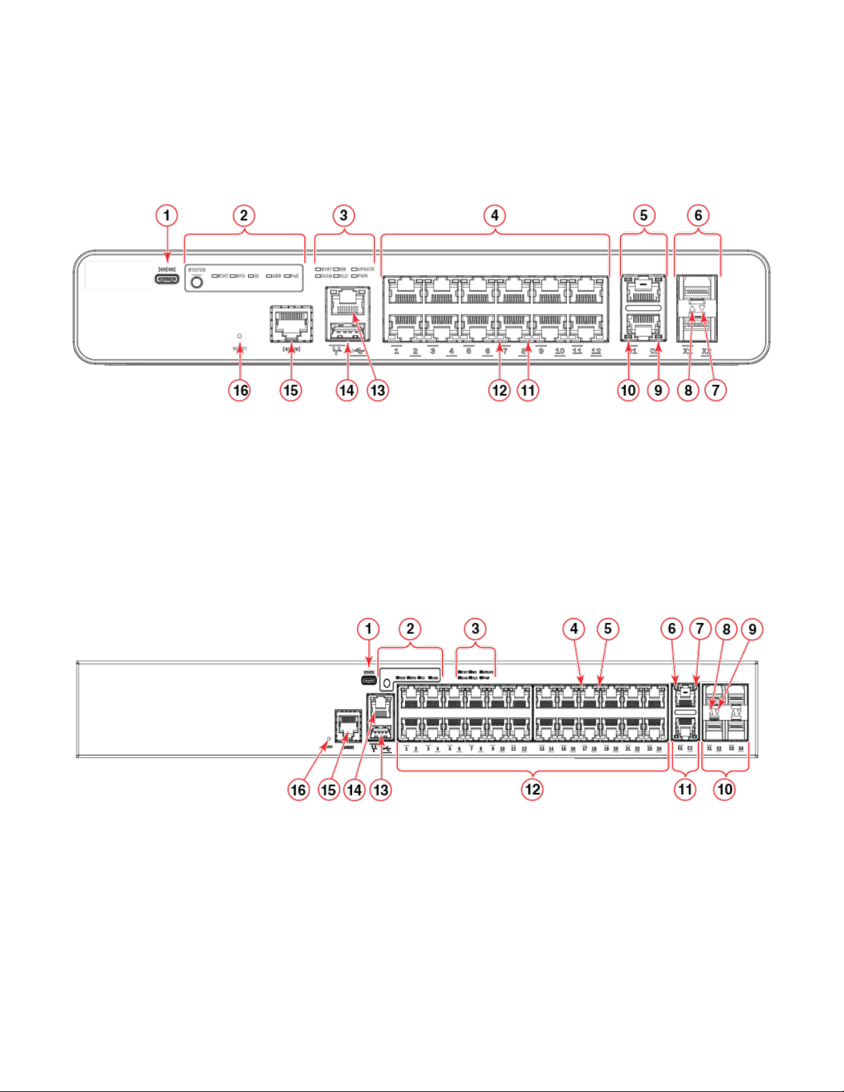
FIGURE 1 Port-side view of ICX 7150-C12P
Port-side view
1. Type-C USB console port
2. Port status mode selection button and LEDs
3. System LEDs
4. Slot 1 (10/100/1000 Mbps RJ-45 downlink) ports
5. Slot 2 (10/100/1000 Mbps RJ-45 uplink) ports
6. Slot 3 (SFP+ uplink or stacking ports)
7. SFP+ Port X2 status LED
8. SFP+ Port X1 status LED
FIGURE 2 Port-side view of ICX 7150-24 and ICX 7150-24P
1. Type-C USB console port
2. Port status mode selection button and LEDs
3. System LEDs
4. RJ-45 downlink port 17 status LED
5. RJ-45 downlink port 17 RX/TX activity LED
6. RJ-45 uplink port C1 status LED
7. RJ-45 uplink port C1 RX/TX activity LED
8. SFP+ port X1 status LED
9. RJ-45 uplink port C2 RX/TX activity LED
10. RJ-45 uplink port C2 status LED
11. RJ-45 downlink port 8 RX/TX activity LED
12. RJ-45 downlink port 8 status LED
13. Out-of-band management port (RJ-45)
14. USB port
15. RJ-45 console port
16. Reset button
9. SFP+ port X2 status LED
10. Slot 3 (SFP+ uplink or stacking) ports
11. Slot 2 (10/100/1000 Mbps RJ-45 uplink) ports
12. Slot 1 (10/100/1000 Mbps RJ-45 downlink) ports
13. USB port
14. Out-of-band management port (RJ-45)
15. RJ-45 console port
16. Reset button
Ruckus ICX 7150 Switch Hardware Installation Guide
53-1004928-02 15

Nonport-side view
FIGURE 3 Port-side view of ICX 7150-48, ICX 7150-48P, and ICX 7150-48PF
1. Type-C USB console port
2. Port status mode selection button and LEDs
3. System LEDs
4. RJ-45 downlink port 29 status LED
5. RJ-45 downlink port 29 RX/TX activity LED
6. RJ-45 uplink port C1 status LED
7. RJ-45 uplink port C1 RX/TX activity LED
8. SFP+ port X1 status LED
9. SFP+ port X2 status LED
Nonport-side view
FIGURE 4 Nonport-side view of ICX 7150-C12P
10. Slot 3 (SFP+ uplink or stacking) ports
11. Slot 2 (10/100/1000 Mbps RJ-45 uplink) ports
12. Slot 1 (10/100/1000 Mbps RJ-45 downlink) ports 37-48
13. Slot 1 (10/100/1000 Mbps RJ-45 downlink) ports 25-36
14. Slot 1 (10/100/1000 Mbps RJ-45 downlink) ports 13-24
15. Slot 1 (10/100/1000 Mbps RJ-45 downlink) ports 1-12
16. USB port
17. Out-of-band management port (RJ-45)
18. Reset button
1. Kensington security slot 2. AC power supply socket
FIGURE 5 Nonport-side view of ICX 7150-24
1. AC power supply socket
16 53-1004928-02
Ruckus ICX 7150 Switch Hardware Installation Guide
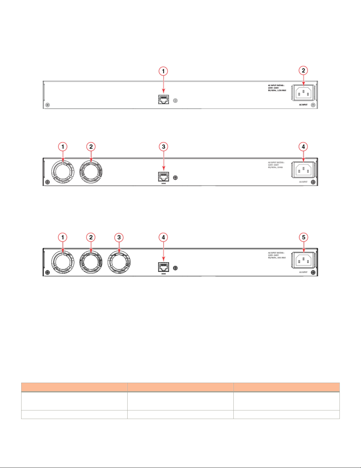
FIGURE 6 Nonport-side view of ICX 7150-48
1. Management console port - RJ-45 2. AC power supply socket
FIGURE 7 Nonport-side view of ICX 7150-24P and ICX 7150-48P
Device management options
1. Fan 1
2. Fan 2
3. Management console port - RJ-45 (available in the front panel for ICX
7150-24P)
4. AC power supply socket
FIGURE 8 Nonport-side view of ICX 7150-48PF
1. Fan 1
2. Fan 2
3. Fan 3
4. Management console port - RJ-45
5. AC power supply socket
Device management options
You can use the management functions built into the device to monitor the topology, port status, physical status, and other information to
help you analyze switch performance and to accelerate system debugging. The device automatically performs power-on self-test (POST)
each time it is turned on. Any errors are recorded in the syslog messages.
You can manage the device using any of the management options listed in the following table.
TABLE 5
Management tool Out-of-band support Reference documents
Command line interface (CLI) Ethernet, serial connection, or USB console Brocade FastIron Command Reference Guide
Standard SNMP applications Ethernet or serial connection Unied IP MIB Reference Guide
Ruckus ICX 7150 Switch Hardware Installation Guide
53-1004928-02 17
Management options for the device
Feature-based Conguration Guides

Device management options
TABLE 5 Management options for the device (continued)
Management tool Out-of-band support Reference documents
Brocade FastIron Web Management Interface Ethernet or connection via IP address Brocade FastIron Web Management Interface
User Guide
NOTE
Not all FastIron features are
supported via the web management
interface.
Brocade Network Advisor (BNA)
NOTE
BNA must be purchased separately.
Ethernet or serial connection Brocade Network Advisor documentation set
18 53-1004928-02
Ruckus ICX 7150 Switch Hardware Installation Guide

Preparing for the Installation
• Safety precautions.............................................................................................................................................................................................19
• Facility requirements.........................................................................................................................................................................................21
• Quick installation checklist.............................................................................................................................................................................22
• Shipping carton contents................................................................................................................................................................................24
Safety precautions
When using this product, observe all danger, caution, and attention notices in this manual. The safety notices are accompanied by
symbols that represent the severity of the safety condition
Refer to Cautions and Danger Notices at the end of this guide for translations of safety notices for this product.
General precautions
DANGER
The procedures in this manual are for qualied service personnel.
DANGER
Before beginning the installation, see the precautions in “Power precautions.”
DANGER
The equipment ports are intra-building type and must not be directly connected to metallic outside plant (OSP) cable
conductors.
CAUTION
Changes or modications made to this device that are not expressly approved by the party responsible for compliance
could void the user's authority to operate the equipment.
CAUTION
Make sure the airow around the front, and back of the device is not
restricted.
CAUTION
Never leave tools inside the chassis.
CAUTION
To protect the serial port from damage, keep the cover on the port when not in use.
CAUTION
Do not install the device in an environment where the operating ambient temperature might exceed 45°C (113°F).
Ruckus ICX 7150 Switch Hardware Installation Guide
53-1004928-02 19
Safety precautions
ESD precautions
DANGER
For safety reasons, the ESD wrist strap should contain a series 1 megaohm resistor.
CAUTION
Before plugging a cable into any port, be sure to discharge the voltage stored on the cable by touching the electrical
contacts to ground surface.
CAUTION
Static electricity can damage the chassis and other electronic devices. To avoid damage, keep static-sensitive devices in
their static-protective packages until you are ready to install them.
NOTE
Wear a wrist grounding strap connected to the chassis ground (if the device is plugged in) or to a bench ground.
Power precautions
DANGER
Make sure that the power source circuits are properly grounded.
DANGER
Make sure you use a power cord displaying the mark of the safety agency that denes the regulations for power cords in
your country. The mark is your assurance that the power cord can be used safely with the device.
DANGER
To reduce the risk of electric shock, disconnect all power cords before servicing.
DANGER
Disconnect the power cord from all power sources to completely remove power from the device.
DANGER
To avoid high voltage shock, do not open the device while the power is on.
DANGER
Batteries used for RTC/NVRAM backup are not located in operator-access areas. There is a risk of explosion if a battery
is replace by an incorrect type. Dispose of used components with batteries according to local ordinance and regulations.
CAUTION
Ensure that the device does not overload the power circuits, wiring, and over-current protection. To determine the possibility
of overloading the supply circuits, add the ampere (amp) ratings of all devices installed on the same circuit as the device.
Compare this total with the rating limit for the circuit. The maximum ampere ratings are usually printed on the devices near
the input power connectors.
Lifting and weight-related precautions
DANGER
Use safe lifting practices when moving the product.
20 53-1004928-02
Ruckus ICX 7150 Switch Hardware Installation Guide
DANGER
Mount the devices you install in a rack as low as possible. Place the heaviest device at the bottom and progressively place
lighter devices above.
DANGER
Make sure the rack housing the device is adequately secured to prevent it from becoming unstable or falling over.
CAUTION
Do not use the port cover tabs to lift the module. They are not designed to support the weight of the module, which can fall
and be damaged.
Laser precautions
DANGER
All ber-optic interfaces use Class 1 lasers.
DANGER
Use only optical transceivers that are qualied by Brocade Communications Systems, Inc. and comply with the FDA Class
1 radiation performance requirements dened in 21 CFR Subchapter I, and with IEC 60825 and EN60825. Optical
products that do not comply with these standards might emit light that is hazardous to the eyes.
Facility requirements
Facility requirements
Before installing the device, be sure the following facilities requirements are met.
TABLE 6 Facility requirements
Type Requirements
General
Electrical
Thermal
• The site should be accessible for installing, cabling, and maintaining the devices.
• Maintain the operating environment as specied in the Technical Specications.
• Allow at least 7.62 cm (3 in.) of space between the front and the back of the device and walls or other obstructions
for proper airow.
• Allow at least 7.62 cm (3 in.) of space at the front and back of the device for the twisted-pair, ber-optic, and
power cabling.
• Allow the status LEDs to be clearly visible.
• Allow for the unit to be connected to a separate grounded power outlet that provides 100 to 240 VAC, 50/60 Hz,
within 2 m (6.6 ft) of each device, and is powered from an independent circuit breaker. As with any equipment, a
lter or surge suppressor is recommended.
• Allow for twisted-pair cables to be routed away from power lines, uorescent lighting xtures, and other sources of
electrical interference, such as radios and transmitters.
• Adequate supply circuit, line fusing, and wire size, as specied by the electrical rating on the switch nameplate
• Circuit protected by a circuit breaker and grounded in accordance with local electrical codes
Refer to the Technical Specications at the end of this guide for complete power supply specications.
• A minimum airow of 39.1 cubic meters/hour (23 cubic ft/min.) available in the immediate vicinity of the switch
Ruckus ICX 7150 Switch Hardware Installation Guide
53-1004928-02 21

Quick installation checklist
TABLE 6 Facility requirements (continued)
Type Requirements
• Ambient air temperature not exceeding 45°C (113°F) while the switch is operating
Rack (when rackmounted)
• One rack unit (1U) in a 48.3 cm (19-inch) rack
• All equipment in the rack grounded through a reliable branch circuit connection
• Additional weight of switch not to exceed the rack’s weight limits
• Temperature: Because the temperature within a rack assembly may be higher than the ambient room temperature,
check that the rack-environment temperature is within the specied operating temperature range.
• Airow: Be sure that the airow direction for all equipment in a rack is the same or consistent.
• Mechanical loading: Do not place any equipment on top of a rack-mounted unit.
• Rack secured to ensure stability in case of unexpected movement
• Circuit overloading: Be sure that the supply circuit to the rack assembly is not overloaded.
NOTE
Although this airow may exceed the airow maximum listed in the device Technical Specications, the
additional airow is recommended to pressurize the inlet (cool isle) side of rack installations relative to
the exhaust side to minimize recirculation of hot air back to the inlet side.
Quick installation checklist
The following checklist provides a high-level overview of the basic installation process from the planning stage to the point where the
device comes online and is ready to be deployed. Completing all the tasks in the suggested order ensures successful installation.
Brocade recommends that you print this checklist and take it to the installation site.
Pre-installation tasks
Review all installation requirements ahead of time as part of your site preparation. Careful planning and site preparation ensures seamless
installation, especially when installing multiple devices.
TABLE 7 Installation prerequisites
Task Task details or additional information Completed
Unpack the device. Take an inventory of the hardware components included in your shipment. Refer to
Shipping carton contents on page 24.
Gather necessary components and
required tools.
Review the safety precautions. Refer to Safety precautions on page 19. For translation of these messages, refer to
Plan the installation. Decide whether you want to install the unit on a at surface or in a rack. For rack
Review and verify installation requirements. Verify that the following requirements are met. Refer to Facility requirements on page 21.
Review the time and items required information at the beginning of each chapter to
ensure you have gathered all necessary components required for the following installation
tasks:
• Mounting the Device on page 25.
• Installing Transceivers and Cables on page 75.
Cautions and Danger Notices on page 105.
installation, obtain the appropriate rack mount kit. Refer to Mounting options on page
25.
• General requirements
• Power requirements
• Environmental requirements
• Clearance for standalone or rack installation
22 53-1004928-02
Ruckus ICX 7150 Switch Hardware Installation Guide

Quick installation checklist
TABLE 7 Installation prerequisites (continued)
Task Task details or additional information Completed
Gather network conguration parameters.
• IP address:
• Subnet mask:
• Default gateway:
• Time zone:
Installation and initial conguration
The initial setup includes mounting the device on a at surface or in a rack and completing the conguration tasks necessary to bring the
device online and verify the operation.
TABLE 8 Installation and basic system
Task Task details or additional information Completed
Mount the device. Choose one of the following mounting options:
Gather all components required for the
initial setup.
Provide power to the device. Refer to Providing power to the device on page 67.
Attach a management station, establish a
console connection, and congure the
various levels of passwords.
Set the IP address, subnet mask, and the
default gateway IP address.
Set the date and time
Customize the host name and chassis
name.
Establish a connection to the out-of-band
management port.
Verify that the device operates correctly.
conguration
• Mount the device on a desktop or at surface. Refer to Mounting on a desktop
or at surface on page 26.
• Mount the compact device with a magnet. Refer to Mounting the compact
device with a magnet on page 28.
• Mount the compact device under a xed surface or desk. Refer to Mounting the
compact device under a xed surface on page 34.
• Mount the compact device directly on a wall. Refer to Mounting the compact
device directly on a wall on page 37
• Mount the device on a wall using the wall mount brackets. Refer to Mounting on
a wall using the wall mount brackets on page 41.
• Mount the device on a two-post rack. Refer to Mounting on a two-post rack on
page 46.
• Mount the device on a universal four-post rack. Refer to Installing the 1U, 1.5U,
and 2U Universal Kit for Four Post Racks (XBR-R000295) on page 51.
Refer to Items required on page 67.
Refer to Establishing a rst-time connection to the console port on page 68. After
completing this task, log in to the console port to congure the device.
Use the ip address command to congure a static device IP address, subnet mask, and
gateway IP address, or you can use a DHCP server to obtain the information dynamically.
Refer to Conguring an IP address for the device on page 71.
• Use the clock set command to set the current date and time for the device.
Refer to Setting the date and time on page 72 for more information.
• Use the hostname command to change the default host name and CLI prompt.
• Use the chassisname command to change the default chassis name or ID.
Refer to Customizing the host name and chassis name on page 71 for more
information.
By establishing a connection to the out-of-band management port, you can complete the
device conguration using an SSH session, Telnet, or management application, such as
Brocade Network Advisor. Refer to Establishing a connection to the out-of-band
management port on page 72.
• Check the LEDs to verify operation of functional parts. Refer to Verifying the
correct operation on page 73.
Ruckus ICX 7150 Switch Hardware Installation Guide
53-1004928-02 23

Shipping carton contents
TABLE 8 Installation and basic system conguration (continued)
Task Task details or additional information Completed
• The following commands can be useful to establish an operational baseline for
the device. Refer to the Brocade FastIron Command Reference guide for more
information on these commands:
– show chassis
– show version
– show cpu
– show ash
– show les
– show run
– show boot-preference
– show conguration
– show running-cong
– show logging
Back up the conguration. Use the write memory command to replace the startup conguration with the running
conguration. Refer to Backing up the running conguration on page 73 for more
information.
Shipping carton contents
When unpacking the device, verify that the contents of the shipping carton is complete. Save the shipping carton and packaging in the
event you need to return the shipment.
• The Ruckus ICX 7150 device
• An accessory kit containing the following items:
– Rack mounting kit containing two L-shaped mounting brackets and two sets of eight sink-head screws (included only with
24-port and 48-port models)
– Wall mounting kit containing two wall-mount screws and two plastic anchors (included only with ICX 7150-C12P)
– Two-post rack kit containing four rack-mounting screws and four cage nuts (included only with 24-port and 48-port
models)
– Four rubber feet
– One AC power cord, shielded (US only)
– One power cord retainer clip
– China-RoHS Hazardous/Toxic Substance statement
– Read Me First document
24 53-1004928-02
Ruckus ICX 7150 Switch Hardware Installation Guide

Mounting the Device
• Mounting options...............................................................................................................................................................................................25
• Precautions specic to mounting................................................................................................................................................................25
• Mounting on a desktop or at surface......................................................................................................................................................26
• Mounting the compact device with a magnet........................................................................................................................................28
• Mounting the compact device under a xed surface..........................................................................................................................34
• Mounting the compact device directly on a wall...................................................................................................................................37
• Mounting on a wall using the wall mount brackets..............................................................................................................................41
• Mounting on a two-post rack........................................................................................................................................................................46
• Installing the 1U, 1.5U, and 2U Universal Kit for Four Post Racks (XBR-R000295).........................................................51
• Time and items required.................................................................................................................................................................................52
• Parts list................................................................................................................................................................................................................. 52
• Flush-front mounting the device in the rack.......................................................................................................................................... 53
• Flush-rear (recessed) mounting the device in the rack......................................................................................................................60
Mounting options
You can install the device in several ways:
• As a standalone unit on a at surface, for example, a table top. Use the rubber feet included with the shipment to secure the
device on the surface. No other equipment is required for desktop installation.
• Only ICX 7150-C12P compact device:
– As a standalone unit using a magnet (ICX6400-C12-MGNT) on a rack or on any surface that is magnetic such as a metal
desk or cabinet.
– As a standalone unit under a xed surface, under a desk, or under a shelf using the wall / under desk mount kit (ICX7000-
C12-WMK) or two-post rack mount kit (ICX7000-C12-RMK ) .
– As a standalone unit directly on a wall using two screws.
• As a standalone unit on a wall using the wall mounting brackets included with the shipment to secure the device on the wall. No
other equipment is required for wall mount installation.
• In a two-post Telco rack: You will need a Universal Two-Post Rack Kit (ICX7000-RMK or ICX7000-C12-RMK ) to install in a
two-post telecommunications (Telco) rack.
• In a four-post EIA rack: You will need a Universal Four-Post Rack Kit (XBR-R000295) to install devices in EIA racks that are
between L-13.7 to 81.28 cm deep (L-5.0 to 32.0 in.), where L is the chassis depth.
Precautions specic to mounting
The following precautions
DANGER
Use safe lifting practices when moving the product.
DANGER
Make sure the rack housing the device is adequately secured to prevent it from becoming unstable or falling over.
Ruckus ICX 7150 Switch Hardware Installation Guide
53-1004928-02 25
specically apply to mounting the device.

Mounting on a desktop or at surface
DANGER
Mount the devices you install in a rack as low as possible. Place the heaviest device at the bottom and progressively place
lighter devices above.
DANGER
This equipment is suitable for mounting on concrete or other noncombustible surfaces only.
CAUTION
Make sure the airow around the front, and back of the device is not
restricted.
CAUTION
Never leave tools inside the chassis.
CAUTION
Use the screws specied in the procedure. Using longer screws can damage the
device.
CAUTION
The device must be turned o and disconnected from the fabric during this
procedure.
Mounting on a desktop or at surface
Complete the following steps to install the device on a desktop or other
the one in the following illustration.
NOTE
The hardware device illustrated in this procedure is only for reference and may not depict the actual device that you are
installing.
at surface. The device you are installing might look dierent than
26 53-1004928-02
Ruckus ICX 7150 Switch Hardware Installation Guide

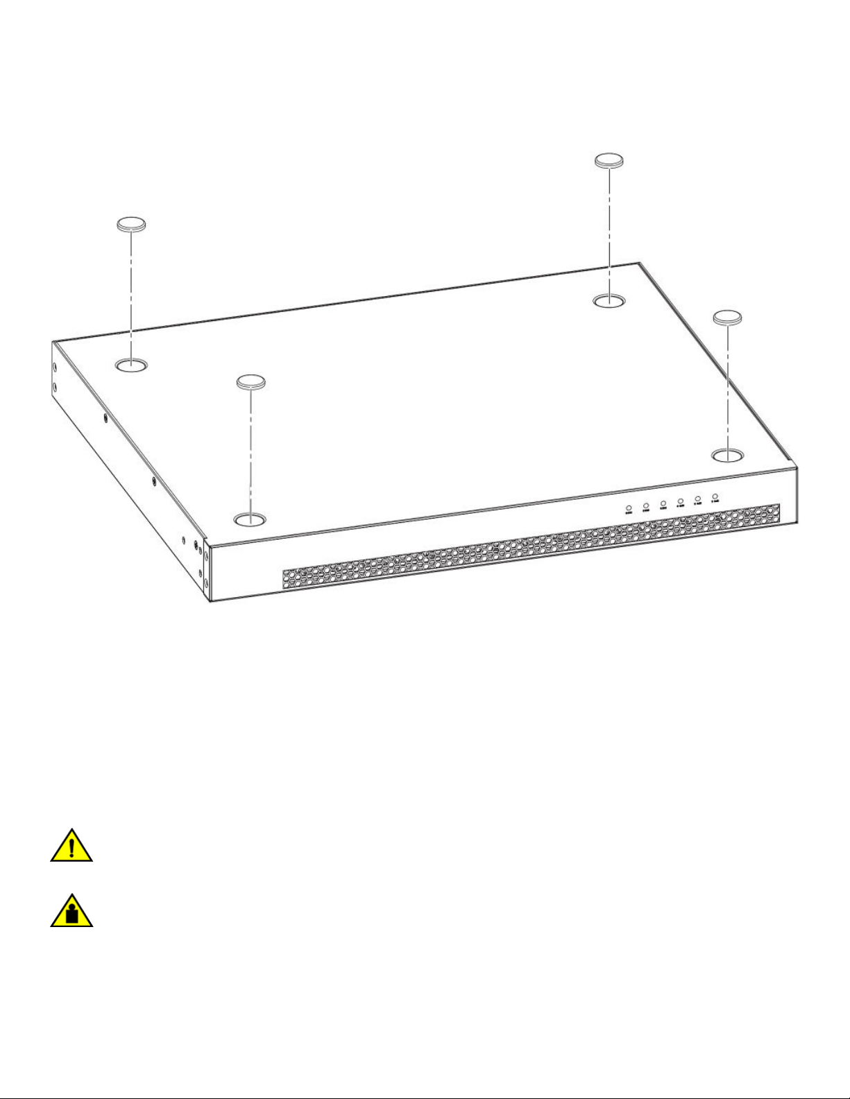
FIGURE 9 Attaching the adhesive feet on a compact device
Mounting on a desktop or at surface
Ruckus ICX 7150 Switch Hardware Installation Guide
53-1004928-02 27
Mounting the compact device with a magnet
FIGURE 10 Attaching the adhesive feet on a 24-port or 48-port device
1. Attach the four adhesive feet to the bottom of the device. If installing multiple devices, attach the adhesive feet to each device.
2. Set the device on a at desktop, table, or shelf near an AC power source. Make sure that adequate ventilation is provided for the
system. A 7.62 cm (3 in.) clearance is recommended on each side.
3. If installing multiple devices, place each device squarely on top of the one below. If you have both compact devices and regular
devices, place the regular devices at the bottom.
4. Power on the system.
Mounting the compact device with a magnet
CAUTION
Ensure that adequate ventilation is provided for the system. A 3 cm clearance is recommended above the device and 8 cm
clearance is recommended on each side.
CAUTION
When magnet mounting a switch, do not install it in a position where it can easily become unstable and fall, causing injury or
damage to the switch.
Use the magnet-mount kit to mount the device on a metal wall or a metal surface, including underneath a metal desk. The magnetmount kit is available for order separately from the device and consists of a single magnet sheet.
28 53-1004928-02
Ruckus ICX 7150 Switch Hardware Installation Guide

Mounting the compact device with a magnet
Before mounting the device to a metal surface using the magnet sheet, ensure that the following requirements are met:
• The magnet sheet is attached to the bottom panel of the device. Refer to Attaching the magnet sheet to the device on page
29.
• Ensure that the device is not installed more than 110 mm. above the oor.
Note the following important installation considerations before installing the device on a metal surface using the magnet mount:
• The strength of the magnet will vary depending on the surface it is used on.
• The magnet’s force might weaken over time. Check the strength of the magnet regularly for about one year. Move the device up
and down and conrm the magnet strength.
When adequate ventilation is provided and the magnet is attached to the device, you can securely mount the device in the following
locations:
• A metal wall or metal surface. Refer to Mounting the device on a metal surface or metal wall on page 30.
• Underneath a metal desktop. Refer to Mounting the device under a metal desk on page 32.
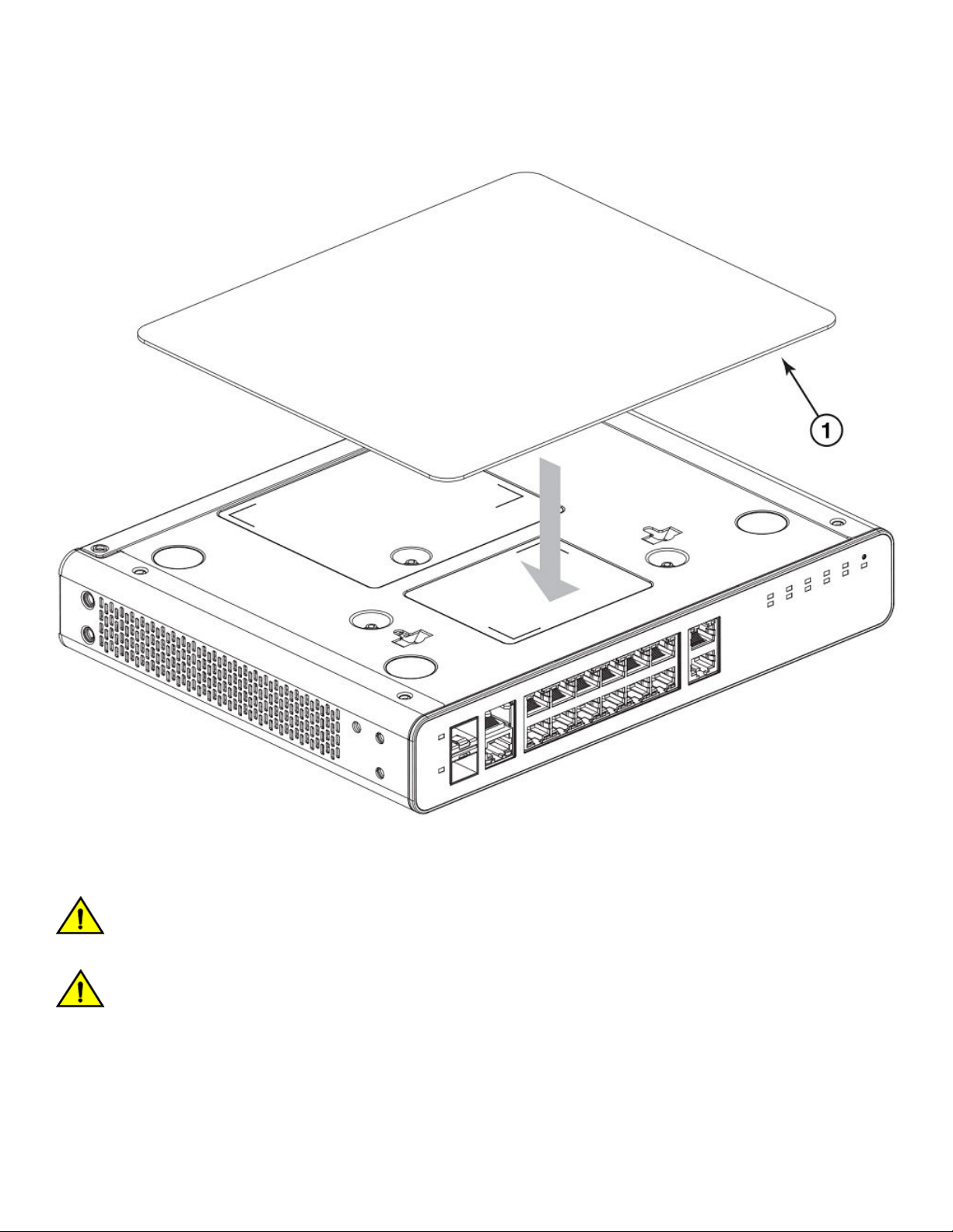
Attaching the magnet sheet to the device
Before mounting the device to a metal surface, place the logo side of the magnet sheet (displaying the Brocade logo) squarely against
the bottom panel of the device to attach the device to the magnet sheet.
CAUTION
The magnet sheet can only be placed against the bottom panel of the device. Do not attempt to attach the magnet sheet to
any other panels on the device.
CAUTION
Before mounting the device using the magnet sheet, make sure the rubber feet are not installed on the device to ensure that
the magnet sheet holds on to the device strongly and does not detach. If the rubber feet are already installed, remove them
rst before attaching the magnet sheet.
Ruckus ICX 7150 Switch Hardware Installation Guide
53-1004928-02 29
Mounting the compact device with a magnet
FIGURE 11 Attaching the logo side of the magnet sheet to the bottom panel of the compact device
Mounting the device on a metal surface or metal wall
CAUTION
Do not mount the device on a surface with the top panel facing downward. Mount the device only on a vertical metal surface
with the front panel port-side facing downward.
CAUTION
Ensure that the metal surface is at and the texture is smooth to hold the device strongly. Check for other conditions that
might impede secure magnetic mount.
Complete the following steps to securely mount a compact device on a metal surface or metal wall:
1. Ensure that the magnet sheet is attached to the bottom panel of the device. Refer to Attaching the magnet sheet to the device
on page 29.
30 53-1004928-02
Ruckus ICX 7150 Switch Hardware Installation Guide
 Loading...