

Page 1

93507757000 Rev F June 2006
RVON-1
for the
KP-32 and KP-812 Family of Keypanels
Page 2

PROPRIETARY NOTICE
The product information and design disclosed herein were originated by
and are the property of Telex Communications, Inc. Telex reserves all
patent, proprietary design, manufacturing, reproduction, use and sales
rights thereto, and to any article disclosed therein, except to the extent
rights are expressly granted to others.
COPYRIGHT NOTICE
Copyright 2006 by Telex Communications, Inc. All rights reserved.
Reproduction, in whole or in part, without prior written permission from
Telex is prohibited.
WARRANTY NOTICE
See the enclosed warranty card for further details.
CUSTOMER SUPPORT
Technical questions should be directed to:
Customer Service Department
RTS/Telex Communications, Inc.
12000 Portland Avenue South
Burnsville, MN 55337 USA
Telephone: 800-392-3497
Fax: 800-323-0498
Factory Service: 800-553-5992
RETURN SHIPPING INSTRUCTIONS
Customer Service Department
Telex Communications, Inc. (Lincoln, NE)
Telephone: 402-467-5321
Fax: 402-467-3279
Factory Service: 800-553-5992
Please include a note in the box which supplies the company name,
address, phone number, a person to contact regarding the repair, the type
and quantity of equipment, a description of the problem and the serial
number(s).
SHIPPING TO THE MANUFACTURER
All shipments of product should be made via UPS Ground, prepaid (you
may request from Factory Service a different shipment method). Any
shipment upgrades will be paid by the customer. The equipment should
be shipped in the original packing carton. If the original carton is not
available, use any suitable container that is rigid and of adequate size. If
a substitute container is used, the equipment should be wrapped in paper
and surrounded with at least four (4) inches of excelsior or similar
shock-absorbing material. All shipments must be sent to the following
address and must include the Proof of Purchase for warranty repair.
Upon completion of any repair the equipment will be returned via United
Parcel Service or specified shipper, collect.
Factory Service Department
Telex Communications, Inc.
8601 East Cornhusker Hwy.
Lincoln, NE 68507 U.S.A.
Attn: Service
This package should include the following:
Page 3

Tabl
e
of
Contents
Chapter 1
Introduction ...............................................................................................................................................................................................1
General Description of the RVON-1 Voice Over Network Card .............................................................................................................1
Features .....................................................................................................................................................................................................1
Specifications ............................................................................................................................................................................................2
Dip Switches .............................................................................................................................................................................................3
Firmware Compatibility Requirements for the RVON-1 Card .................................................................................................................3
Flash Chip Replacement ............................................................................................................................................................................4
Chapter 2
Installation .................................................................................................................................................................................................5
Installation of the RVON-1 Card ..............................................................................................................................................................5
RVON-1 Relay ..........................................................................................................................................................................................7
Addresses and the RVON-1 ......................................................................................................................................................................7
Configure the RVON-1 from the KP-32 ...................................................................................................................................................8
Set the IP Address from the Service Level Menu..................................................................................................................................... 8
Select an RVON Connection from the Top Level Menu ...........................................................................................................................9
Configure the RVON-1 from the KP-812 ...............................................................................................................................................10
Set the IP Address from the Service Level Menu ...................................................................................................................................10
Select an RVON Connection from the Top Level Menu ........................................................................................................................11
Configure the RVON-8 using AZedit to contact the RVON-1 ...............................................................................................................11
Chapter 3
Configuration ......................................................................................................................................................................................... 13
Download RVON-1 Firmware Through AZedit .....................................................................................................................................13
Appendix A
Basic Network Configuration ..................................................................................................................................................................15
Basic Network Configuration ..................................................................................................................................................................15
LAN (local area network) vs. WAN (wide area network) ......................................................................................................................15
LOCAL AREA NETWORK ...................................................................................................................................................................15
WIDE AREA NETWORK ......................................................................................................................................................................16
ACCESSING THE WIDE AREA NETWORK (WAN) ........................................................................................................................17
NETWORK ADDRESS TRANSLATION (NAT) .................................................................................................................................17
PORTS ....................................................................................................................................................................................................17
IP ADDRESSES .....................................................................................................................................................................................18
Ping a Computer ......................................................................................................................................................................................19
POSSIBLE PITFALL WITH ROUTERS, GATEWAYS, AND SWITCHES .......................................................................................20
RVON Configuration ..............................................................................................................................................................................21
Network Terminology............................................................................................................................................................................. 22
Page 4

Tabl
e
of
Contents
Appendix B
Telnet & Serial Port Programming ..........................................................................................................................................................25
RVON Serial and Telnet Commands ......................................................................................................................................................25
Setup ........................................................................................................................................................................................................25
How to Configure the RVON-1 using Telnet ......................................................................................................................................... 26
Page 5

1
CHAPTER 1
Introduction
General Description of the RVON-1 Voice Over Network Card
Installed directly into KP-32 or KP-812 keypanels, the RVON-1 provides voice over IP (Internet Protocol) communications,
for the RTS™ ADAM Intercom family. In general, voice over IP means sending voice information in digital form using discrete packets rather than the traditional hardwire connection. The RVON-1 delivers an integrated solution for connecting keypanels to the Intercom matrix over standard IP networks.
The RVON-1 is compatible with any RTS™ Matrix Intercom System equipped with a suitable RVON interface. In conjunction
with any new or existing KP-32 or KP-812 keypanel, the RVON-1 brings a new level of enterprise-wide and remote access
functionality to your RTS™ Matrix Intercom.
The RVON-1 card is configurable through the keypanel service menu and Telex’s AZedit configuration software. It is also
fully compatible with internationally recognized standards and supports the following protocols: G.711, G.729 AB, and G.723
(2 bit rates).
The RVON-1 reaffirms RTS’ history of providing support for the latest technology in a fully supported backward compatible
manner to all its RTS™ products.
Features
Installation The RVON-1 provides a single RJ-45 Ethernet connection for use with a 10 BAS-T or 100 BASE-TX
network.
1 Channel of AudioIN
and OUT
The RVON-1 card supports one channel IN and OUT and has configurable network and bandwidth
parameters that can be tailored to individual network functions.
Ethernet Compatible The RVON-1 card uses standard Ethernet protocols and is compatible with 10 BASE-T and 100 BASE-
TX Ethernet compliant devices and networks.
AZedit Configurations Users have the ability to adjust the audio parameters of the RVON-1 channel to optimize the available
bandwidth.
Swappable Between
Ethernet and AIO
Connection
When connected ton an Ethernet LAN, audio comes from the RVON-1 card; and, when an Ethernet link
is not present, the audio comes from the AIO connection. Note, the user does not need to remove the
RVON-1 card to switch to AIO mode.
Page 6

Introduction
2
Specifications
DIGITAL
CONNECTIONS
• RJ-45 Ethernet via backcard
• 14-pin KP Compatible Expansion Connector
Pin 1...............................................................................................................................5 Volt Analog
Pin 2........................................................................................................................................ -12 Volt
Pin 3........................................................................................................................................+12 Volt
Pin 4................................................................................................................................5 Volt Digital
Pin 5................................................................................................................................Analog GND
Pin 6.................................................................................................................................Digital GND
Pin 7.......................................................................................................................To Matrix Audio L
Pin 8................................................................................................................................................NC
Pin 9.................................................................................................................. From Matrix Audio L
Pin 10......................................................................................................................................RS485L
Pin 11................................................................................................................From Matrix Audio H
Pin 12..............................................................................................................................................NC
Pin 13.................................................................................................................... To Matrix Audio H
Pin 14......................................................................................................................................RS485H
Power............................................................................................................... Powered internally from keypanel
motherboard
Physical ........................................................................................................... 2.5”W x 5.75”L (63.5mmW X
146.05mmL)
Compression Audio Bit Rate Coding Delay Playout Delay IP Bandwidth
G.711 64k 125μs 20-60ms 160-224 kbps
G.729AB 8k 10ms 20-120ms 32-112kbps
G.723 5.3k/6.3k 30ms 60-120ms 29-45kbps
*Data depends on CODEC selection.
NOTE: The Playout Delay and Bandwidth depend on the configured amount of audio per packet.
Page 7

3
Dip Switches
Dip Switches
Firmware Compatibility Requirements for the RVON-1 Card
Switch 1 Reserved
Switch 2 Disable Telnet Shell
Default Setting: OFF (Telnet Enabled)
Description: The Telnet shell allows you to access configuration options through the use of Telnet. When DIP switch 2 is OFF, you
can use Telnet to access configuration options on the RVON-1 card. Turn DIP switch 2 ON to disable the Telnet shell
Switch 3 Enable Boot Downloader
Default Setting OFF (Boot Downloader Disabled)
Description The purpose of the boot downloader is to allow you to recover from having your main application image corrupted
(either by bad flash programming or by downloading an invalid image). Turn DIP switch 3 ON to enable the boot
downloader.
Switch 4 Debug Only!
Default Setting OFF
Description DIP switch 4 should always be left in the OFF position. It is reserved for debugging and can have unintended
consequences.
Description Version
Master Controller 9.19.0 or later
Peripheral Controller 10.10.0 or later
DBX 1.10.1 or later
AZedit 2.06.06 or later
RVON-8 1.1.0 or later
KP-32 2.0.0 or later
TABLE 1.
Compatibility Requirements for the RVON-1 card.
Page 8
Introduction
4
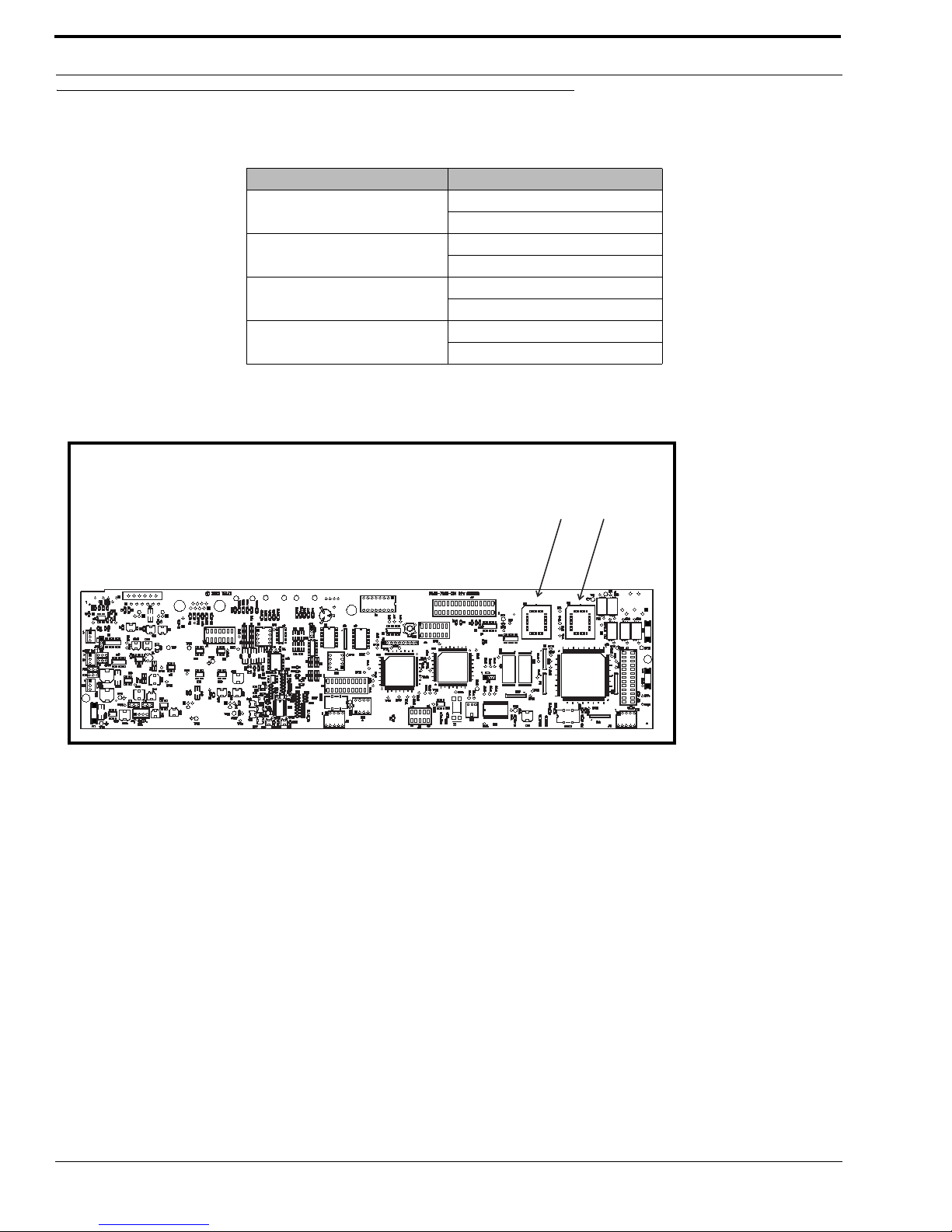
Flash Chip Replacement
1.
Keypanel Flash Chip Replacement
KP-32 Standard
9015-7656-002 (U2)
9015-7656-003 (U3)
KP-32 (Japan)
9015-7656-042 (U2)
9015-7656-043 (U3)
KP-632
9015-7656-202 (U2)
9015-7656-203 (U3)
KP-832
9015-7656-302 (U2)
9015-7656-303 (U3)
TABLE 2 .
Flash Chip replacement part numbers.
Figure 1. Flash Chip placement on the KP-32 motherboard
U2
U3
Flash Chips
U2
U3
Flash Chips
Page 9
5
CHAPTER 2
Installation
Installation of the RVON-1 Card
Before using the RVON-1 card with the KP-32, a few modifications need to be made to the keypanel. If the serial number on
your KP-32 keypanel is 61170, you will need to update you backpanel with the Ethernet RJ-45 connection (part number 9080-7656-002) knockout present. Also, the KP-32 flash chips need to be replaced with larger flash chips (4MB) see Table 2,
“Flash Chip replacement part numbers.,” on page 4.
To install the RVON-1 card, do the following:
1. Remove the cover from the KP-32 keypanel.
2. If present, remove the GPI/O board.
The GPI/O board contains the general purpose input and output connections located on the back cover.
3. Using a chip extractor, carefully remove and replace the flash chips located at U2 and U3 on the KP-32 Motherboard, see
“Flash Chip Replacement” on page 4.
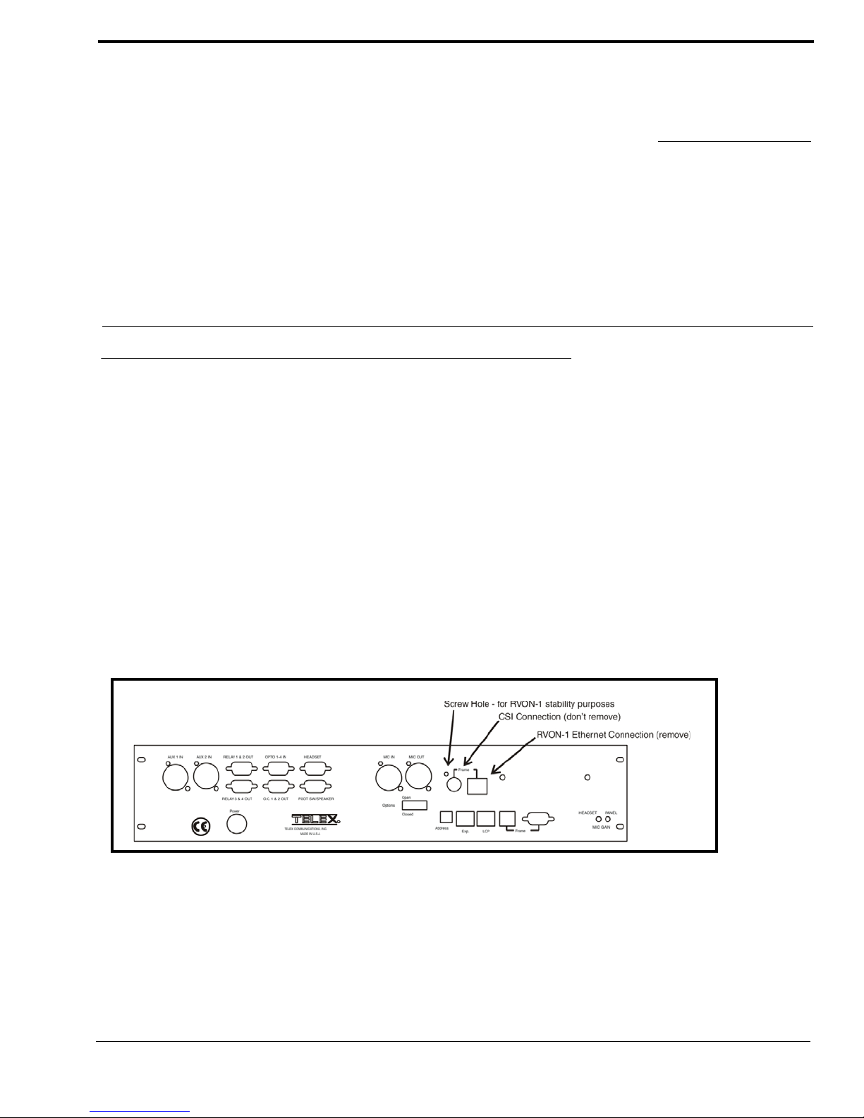
4. Using a hammer and screwdriver, remove the specified knockout pieces, see Figure 2..
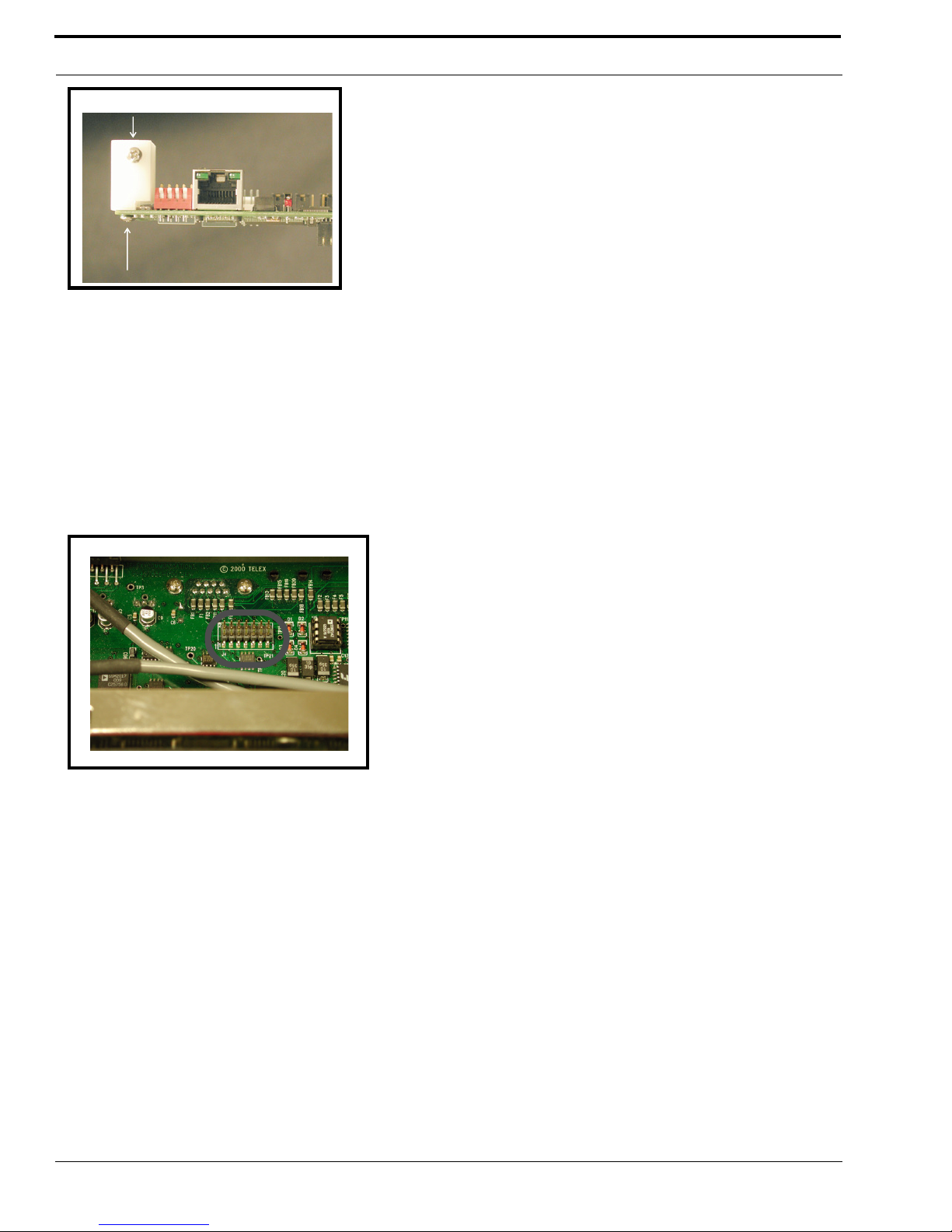
5. Mount the supplied spacer on the RVON-1 card on the corner of the card near the DIP switch. See Figure 3 on page 6.
6. Securely connect the RVON-1 card to the KP-32 motherboard , see page X for connector specifics.
Figure 2. Knock out positions for the RVON-1 card on the KP-32
Page 10
Installation
6
7. Replace the GPI/O board.
8. Re-attach the backplate to the KP-32 keypanel. Be sure to secure the spacer with a screw in the back plate. See Figure 2 on
page 5
9. Replace the cover on the KP-32 keypanel.
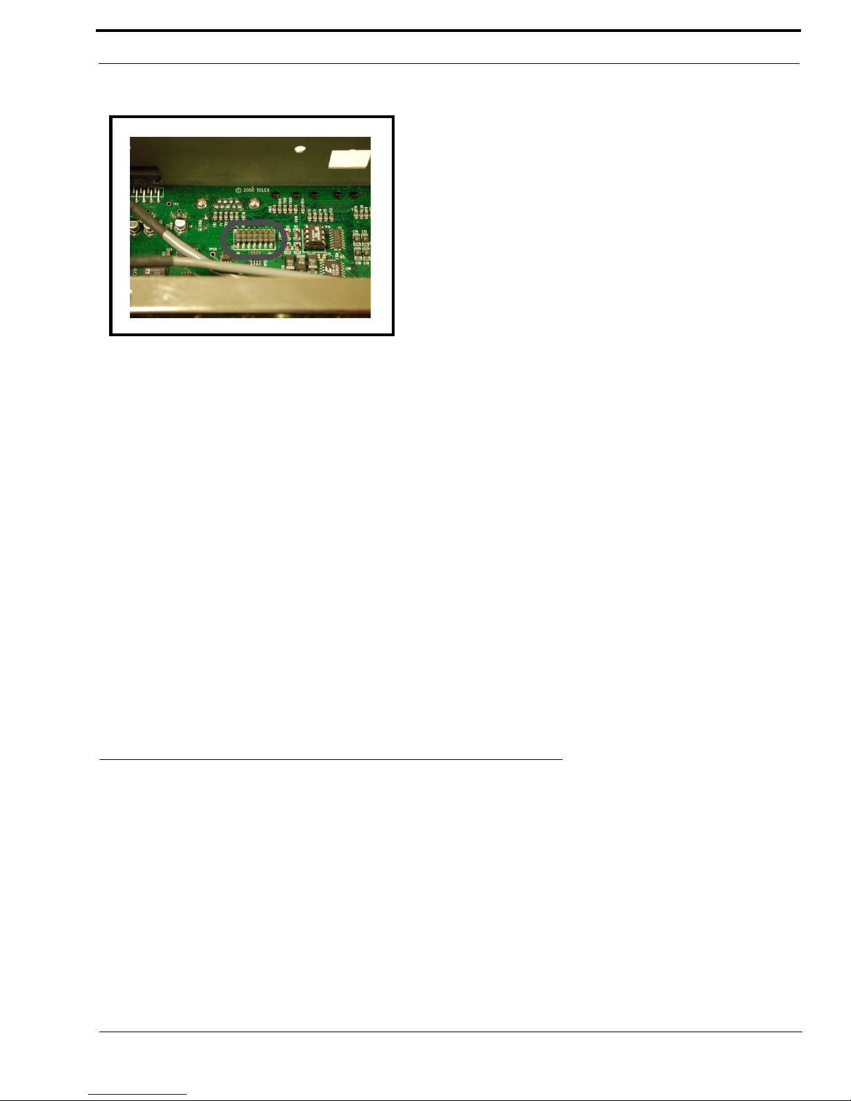
In the KP-32 keypanel, the RVON-1 card connects to the KP-32 by way of the J2 connector on the RVON-1, attached to J4 on
the KP-32 header.
10. Gently secure the board in place (see Figure 4.).
,
In the KP-812, the RVON-1 card connects to the KP-812 by way of the J2 connector on the RVON, attached to J37 on the KP812 header.
Figure 3. The placement of the spacer and screw position on the RVON-1 card.
Figure 4. The J4 connector on the KP-32 board.
Page 11
7
Addresses and the RVON-1
11. Gently secure the board in place
NOTE: Be sure the orientation of the board is correct, otherwise undesirable effects may occur. Make sure the RJ-45
connection is positioned so it will fit through the specified knockout on the back cover. When installing the RVON-1 card in an
existing KP-32 or KP-812, each keypanel needs to be upgraded to include the following:
KP-32
•A backplate that allows for the RJ-45 connection (Ethernet).
•Larger flash chips.
KP-812
•A backplate that allows for the RJ-45 connection (Ethernet)
•Extension for the RJ-45 connector.
RVON-1 Relay
When connected to an Ethernet LAN, audio comes from the RVON-1 card; and, when Ethernet is not plugged in, the audio
comes from the AIO connection. Note, the user does not need to remove the RVON-1 to switch to AIO mode.
WARNING: You cannot have both an Ethernet connection and an AIO connection simultaneously. If the Ethernet and AIO
are connected simultaneously, no audio communication will occur.
Addresses and the RVON-1
Because the RVON-1 has an Ethernet interface, it is required to have a MAC (Media Access Control) Address. This is a low
level address that contains 48 bits. Do NOT confuse this address with an IP (Internet Protocol) Address. In order to be IP compliant, all cards must have a unique MAC ID when shipped from the manufacturer. Typically, the MAC ID of a piece of hardware, such as the RVON-1 card, has a fixed or static address. Where as the RVON-1 card’s IP Address can change over time.
The MAC Address uniquely identifies each node of a network and interfaces directly with the network media. The RVON-1
card has a small 8-pin serial device on the board that the processor can read the unique MAC Address from. For more
information on MAC IDs, contact technical support.
NOTE: Each RVON-1 card needs to be programmed with its own IP Address.
Figure 5. The J37 connector on the KP-812 board.
Page 12

Installation
8
Configure the RVON-1 from the KP-32
To use the RVON-1 with the KP-32, the KP-32 firmware must be at version 2.0.0 or higher. In turn, the firmware requires that
larger flash chips be used as well (see See “Flash Chip replacement part numbers.” on page 4.).
TOP LEVEL MENU, SERVICE, RVON SETUP
Set the IP Address from the Service Level Menu
The RVON-1 card, when shipped has a default IP Address already configured. This must be changed in order for the RVON-1
card to function properly because the pre-configured IP Address may not work with your network.
To set the IP Address, do the following:
1. On the KP-32, press Menu.
The top level menu appears.
2. Using the ⎠⎠, scroll to Service.
3. Press PGM.
The Service menu appears.
4. Using the ⎠⎠, scroll to RVON Setup.
5. Press PGM.
The IP Address menu item appears.
6. Press PGM.
The actual IP Address appears.
7. Enter the first number in the IP Address.
This activates the first octet of the IP Address and clears the rest of the IP Address.
8. Press PGM.
This confirms the first octet in the IP Address and moves you to the second octet.
NOTE: Press PGM to skip over any octet that does not need modifications.
9. Repeat steps 7 and 8 until the entire IP Address is entered.
10. Press PGM.
The Netmask menu item appears.
NOTE: Once you have entered the IP Address, you will then enter the Netmask. The Netmask is a string of numbers similar to
an IP Address, except that it masks or screens out the network part of an IP Address so that only the host computer part of the
address remains (for example, 255.255.255.0).
11. Press PGM.
The actual Netmask appears.
12. Enter the first number in the Netmask.
This activates the first octet of the Netmask and clears the rest of the Netmask.
13. Press PGM.
This confirms the first octet in the Netmask and moves you to the second octet.
NOTE: Press PGM to skip over any octet that does not need modifications.
14. Repeat steps 13 and 14 until the entire Netmask is entered.
15. Press PGM.
The Gateway IP Address menu item appears.
NOTE: Once you have entered the Netmask, you may need to enter the Gateway IP Address. A Gateway is a note (for
example, a computer) on a network that serves as an entrance to another network.
Page 13

9
Configure the RVON-1 from the KP-32
16. Press PGM.
The actual Gateway IP Address appears.
17. Enter the first number in the Gateway IP Address.
This activates the first octet of the Gateway IP Address and clears the rest of the address.
18. Press PGM.
This confirms the first octet in the Gateway IP Address and moves you to the second octet.
NOTE: Press PGM to skip over any octet that does not need modifications.
19. Repeat steps 19 and 20 until the entire Gateway is entered.
20. Press PGM.
21. Press CLR to exit the menu.
The changes are now enabled.
NOTE: You can still set the IP Address without being connected to an Ethernet LAN. Once you have entered the IP
information you will be prompted to perform a Save Cfg. The address is saved in the keypanel until the RVON-1 is connected
to an Ethernet LAN.
TOP LEVEL MENU, RVON CONN.
Select an RVON Connection from the Top Level Menu
The RVON Conn menu contains a list of connection offers from intercoms. This menu allows the keypanel to dynamically
select an intercom and port to which it will connect.
To select a connection offer, do the following:
1. On the KP-32, press Menu.
The top level menu appears in the CWW window.
2. Using the ⎠⎠, scroll to RVON Conn.
3. Press PGM.
The currently selected intercom port appears in the CWW window. If you have not previously selected a connection, you
will see “none”.
4. Using the ⎠⎠, scroll to the connection offer that you want to accept.
5. Press PGM.
♦
<connection offer> appears. The arrow to the left of the offer designates which connection offer was chosen.
6. Press CLR to exit.
The keypanel will now connect to the selected intercom port.
Page 14

Installation
10
Configure the RVON-1 from the KP-812
TOP LEVEL MENU, SERVICE, RVON SETUP
Set the IP Address from the Service Level Menu
The RVON-1 card, when shipped has a default IP Address already configured. This must be changed in order for the RVON-1
card to function properly because the pre-configured IP Address may not work with you network.
To set the IP Address, do the following:
1. On the KP-812, scroll to Menu.
The top level menu appears.
2. Turning the encoder knob, scroll to Service.
3. Tap t he encoder knob to select Service.
The Service menu appears.
4. Turning the encoder knob, scroll to RVON Setup.
5. Tap t he encoder knob to select RVON Setup.
The IP Address menu item appears.
6. Tap t he encoder knob to select IP Address.
The actual IP Address appears.
7. Enter the first number in the IP Address.
This activates the first octet of the IP Address and clears the rest of the IP Address.
8. Tap t he encoder knob.
This confirms the first octet in the IP Address and moves you to the second octet.
NOTE: Tap the encoder knob to skip over any octet that does not need modifications.
9. Repeat steps 7 and 8 until the entire IP Address is entered.
10. Ta p the encoder knob.
The Netmask menu item appears.
NOTE: Once you have enter the IP Address, you will then enter the Netmask. The Netmask is a string of number similar to an
IP Address, except that it masks or screens out the network part of an IP Address so that only the host computer part of the
address remains (for example, 255.255.255.0).
11. Tap the encoder knob to select Netmask.
The actual Netmask appears.
12. Enter the first number in the Netmask.
This activates the first octet of the Netmask and clears the rest of the Netmask.
13. Ta p the encoder knob.
This confirms the first octet in the Netmask and moves you to the second octet.
NOTE: Tap the encoder knob to skip over any octet that does not need modification.
14. Repeat steps 13 and 14 until the entire Netmask is entered.
15. Ta p the encoder knob.
The Gateway IP Address menu item appears.
NOTE: Once you have entered the Netmask, you may need to enter the Gateway IP Address. A Gateway is a node (for
example, a computer) on a network that serves as an entrance to another network.
16. Tap the encoder knob to select Gateway.
The actual Gateway IP Address appears.
Page 15

11
Configure the RVON-8 using AZedit to contact the RVON-1
17. Enter the first number in the Gateway IP Address.
This activates the first octet of the Gateway IP Address and clears the rest of the address.
18. Tap t he encoder knob.
This confirms the first octet in the Gateway IP Address and moves you to the second octet.
NOTE: Press PGM to skip over any octet that does not need modifications.
19. Repeat steps 19 and 20 until the entire Gateway is entered.
20. Tap t he encoder knob.
21. Press and hold the encoder knob to exit the menu.
The changes are now enabled.
NOTE: You can still set the IP Address without being connected to an Ethernet LAN. Once you have entered the IP
information, you will be prompted to perform a Save Cfg. The address is saved in the keypanel until the RVON-1 is connected
to an Ethernet LAN.
TOP LEVEL MENU, RVON CONN.
Select an RVON Connection from the Top Level Menu
The RVON Conn. menu is a list of connection offers from other intercoms. This menu allows the keypanel to dynamically
select an intercom and port to which it will connect.
To select the connection offer, do the following:
1. Using the encoder knob on the KP -812, scroll to RVON Conn.
2. Tap the encoder knob to select RVON Conn.
The currently selected connection offer appears in the CWW window. If you have not previously selected the connection,
you will see “none”.
3. Turn the encoder knob to scroll to the connection offer to which you want to connect.
4. Tap the encoder knob to select the connection.
The connection offer begins to flash indicating that it has been selected.
5. Press and hold the encoder knob to exit the menu.
The keypanel will now connect to the select port.
Configure the RVON-8 using AZedit to contact the RVON-1
To configure the RVON-1 card, do the following in AZedit:
1. From the Status menu, select I/O Cards.
The I/O Card Status screen appears showing the types of installed.
Page 16
Installation
12
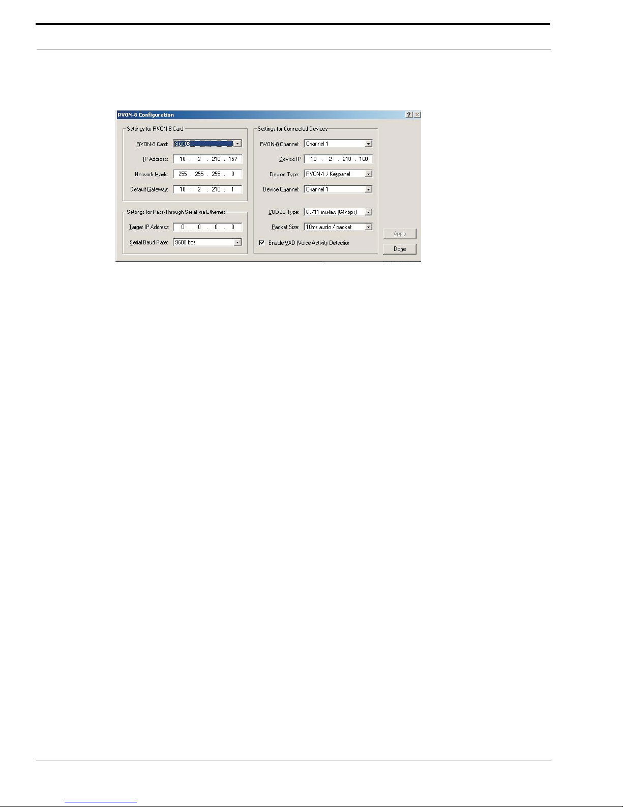
2. Right click on an RVON-8 card and select RVON-8 Configuration
The RVON-8 Configuration screen appears.
NOTE: The RVON-8 you use should be already configured. If it is not configured, refer to your RVON-8 Card User Manual.
Remember, the RVON-1 has only one channel that can be configured.
3. In the RVON-8 Channel drop down list, select the channel that will be used to communicate to the RVON-1 card across
network.
4. In the Device IP field, enter the IP Address for the RVON-1 card.
5. From the Device Type drop down list, select RVON-1/Keypanel.
6. From the Device Channel drop down list, select Channel 1.
There may be two channels listed, but the connection can only be made through channel 1.
7. From the CODEC Type drop down list, select the CODEC type.
8. From the Packet Sized drop down list, select the size of each audio packet.
NOTE: A CODEC is an algorithm used to compress audio. Codecs dictate the quality of audio you hear and the network
bandwidth used. The packet size determines how much audio data is carried across the network in each transmitted packet.
The CODEC type and packet size chosen require different amounts of bandwidth from the network. As with the CODEC type,
the packet size you choose for the audio transfer will affect the audio you hear and the bandwidth you use over the network.
The larger the audio packet you choose to use, the lower the bandwidth used. However, the larger packet size can result in a
higher delay and longer gaps if the packet is lost. On the other hand, smaller packet sizes result in larger bandwidth use, but
lower delays and smaller gaps if the packet is lost. The Intercom System Engineer and the Network Designer may want to
work together in choosing the CODEC type and packet size suitable for the size of the network, so degradation of network
resources does not occur.
9. Select Enable VAD (Voice Activation Detection), if you want to conserve bandwidth when the audio level is below a
given threshold.
NOTE: VAD saves network bandwidth by stopping the flow of audio packets when silence is detected. VAD is similar to
VOX.
10. Once you are completely finished, click Apply.
Page 17
13
CHAPTER 3
Configuration
Download RVON-1 Firmware Through AZedit
NOTE: AZedit sends firmware directly to the RVON-1 card over Ethernet. This is different from other I/O cards (except the
RVON-8) that receive the firmware from the Master Controller. For this reason, verify the PC running AZedit is able to contact
the RVON-1 card via the network, or is configured with a Gateway IP Address that can contact the RVON card. If it is not,
AZedit will not be able to find the RVON-8 card. To test the connection, pin the RVON card from a command line. For more
information on how to test for a connection, see Appendix A.
To download the RVON-1 Firmware, do the following:
1. Open AZedit.
2. From the Status menu, select Software Versions and then Keypanels.
The Keypanel Version screen appears.
3. On the Keypanel Version screen, select the Show RVON-1 Versions check box.
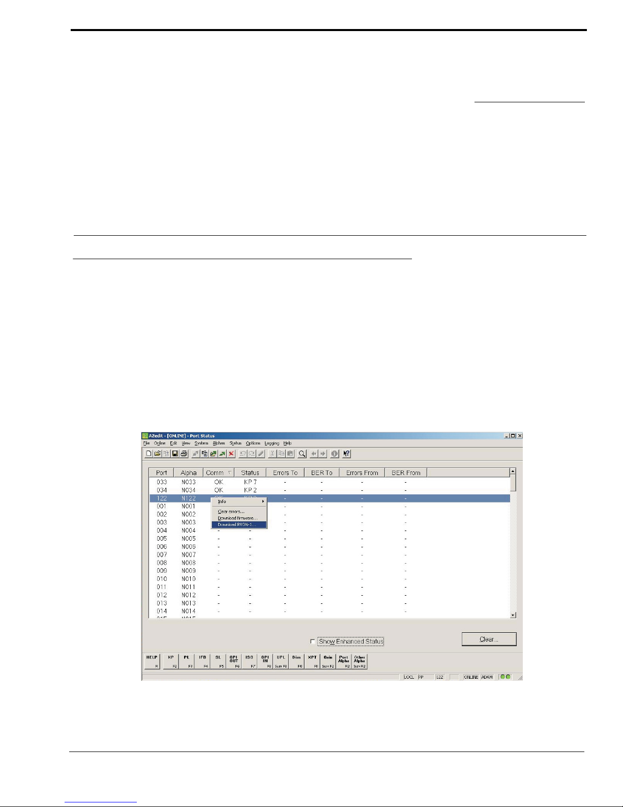
4. Select and right click the keypanel which has the RVON-1 installed, and then select Download RVON-1.
The Download Device Firmware screen appears.
Page 18

Configuration
14
5. Using the Browse feature, browse to the file to be downloaded.
6. Click Open.
The Download Device Firmware screen appears.
7. Click Begin Download.
The download begins.
8. Click OK.
The RVON-1 firmware download is complete. This takes a minute or two to occur.
WA R NI N G !: Do NOT power down the keypanel until you have verified the new version information from AZedit. If the card
loses power while reprogramming the onboard flash memory, the card may become unbootable and may need to have its flash
chips reprogrammed at the factory.
9. Verify the correct version is shown on the Keypanel Version screen.
NOTE: You can also download the RVON-1 firmware through Status > Port s. You will not be able to check the version once
the download is completed from the Port Status screen.
Page 19

15
CHAPTER 4
Basic Network Configuration
Basic Network Configuration
This section covers basic network configuration set-up and testing. Also covered are basic concepts and operations, including
the difference between LAN and WAN networks and how IP Addressing is used.
In a networked environment, such as a company, typically there are many computers connected together using a router or a
switch. In larger companies, there may be several different routers distributed in buildings and plant locations. A router allows
any LAN-side computer to communicate with other computers and devices outside the LAN (local area network). Routers
send data packets from one place to another place on a network. routers use network addresses to route packets to the correct
destination. For example, in a TCP/IP network, the IP (internet protocol) address of the network interface is used to direct
router destinations.
Because routers help computers inside the LAN “talk” with computers outside of the LAN, the security of a company’s LAN
may be compromised by gaps of open ports in the router. Security measures may have been instituted to compensate for these
vulnerabilities. Consult you network administrator to learn about the security measures taken to protect your network. VPN, or
virtual private network, is one such security measure to protect the intelligence of the LAN. A computer outside the LAN must
have an address or key known by the VPN to allow access to the LAN. Many companies use a VPN to connect two different
LANs, thus allowing the transfer of data between two networks.
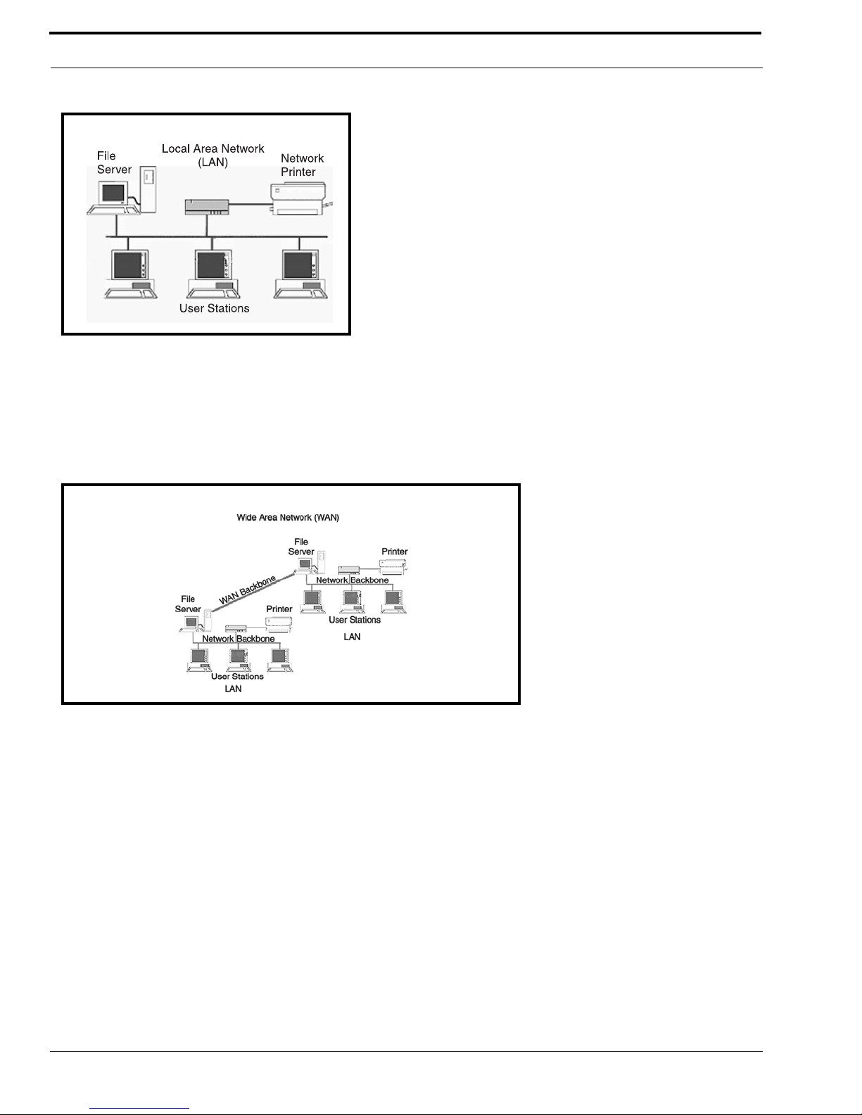
LAN (local area network) vs. WAN (wide area network)
LOCAL AREA NETWORK
Simply put, a LAN is a computer network that connects a relatively small area (a single building or group of buildings). Most
LANs connect workstations and computers to each other. Each computer (also known as a “node”), has its own processing unit
and executes its own programs; however, it can also access data and devices anywhere on the LAN. This means many users
can access and share the same information and devices. A good example of a LAN device is a network printer. Most
companies cannot afford the budgetary or hardware expense of providing printers for each of its users; therefore, one printer
(or device) is placed on the LAN where every user can access the same printer.
The LAN uses IP Addresses to route data to different destinations on the network. An IP Address is a 32-bit numeric address
consisting of four numbers separated by periods (for example, 1.160.10.240).
NOTE: For more information on IP Addresses, see you local network administrator.
Page 20
Basic Network Configuration
16
WIDE AREA NETWORK
A wide area network (WAN) connects two or more LANs and can span a relatively large geographical area. For example,
Telex Headquarters in Burnsville, MN is connected to several branch offices in Nebraska and Arkansas over a WAN. The
largest WAN in existence is the Internet.
Figure 6. Local Area Network Diagram
Figure 7. Wide Area Network Diagram
Page 21
17
Basic Network Configuration
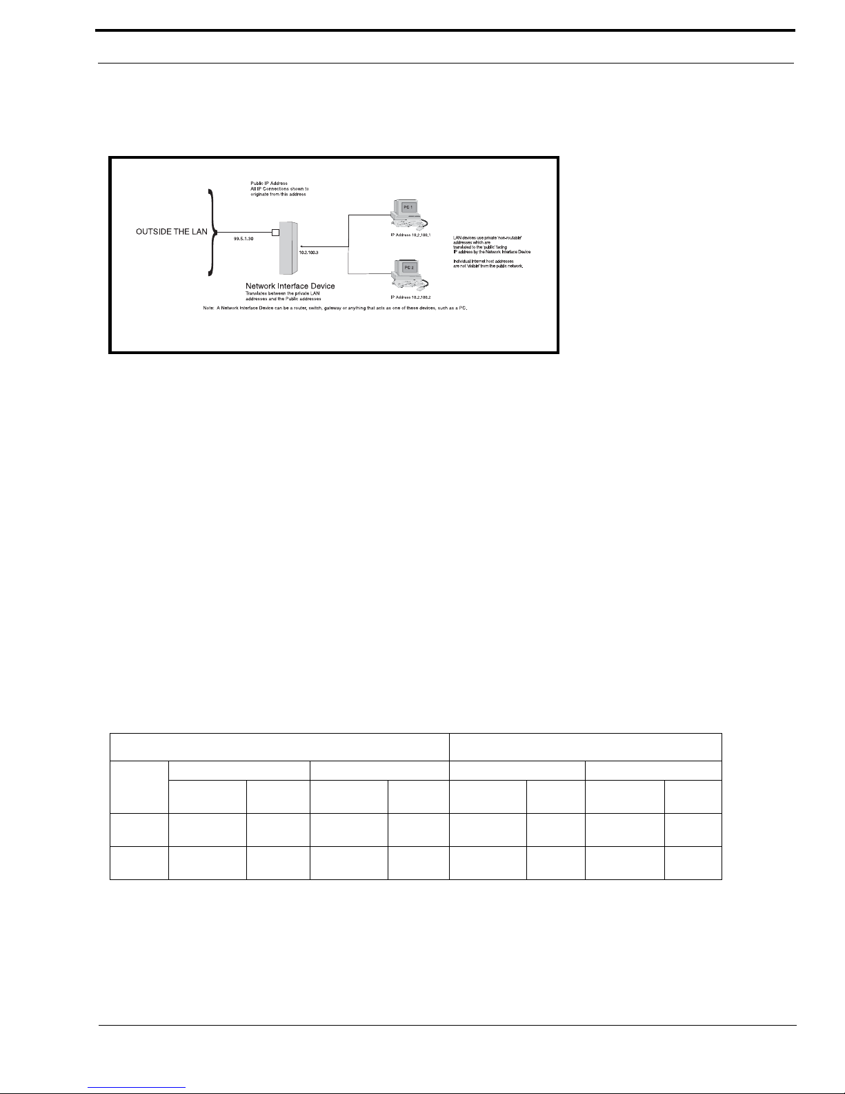
ACCESSING THE WIDE AREA NETWORK (WAN)
Figure 3 shows LAN IP Addresses using a common IP Address, 10.2.100.X (192.168.X.X is another common address). Most
devices are shipped with these addresses as its default. It is recommended to use these addresses for LANs.
NETWORK ADDRESS TRANSLATION (NAT)
Using the initial IP Address, then converting it to a valid WAN IP Address is how the network address translation works, in
theory. Once the IP address is changed, it is up to the network interface device (such as a router, gateway, switch, etc.) to keep
track of which computers are talking on which ports. For example, if two local devices (PC1 and PC2 in Figure 3) both wanted
to talk via port 1031, then the network interface device would have to change one of the port requests to the next available port,
1032.
PORTS
In general, a network port is an endpoint to a logical connection. The port number identifies what type of port it is. For
example, port 80 is used for HTTP traffic. When you type an address into the address bar of a web browser, your computer
goes to find an IP Address for the url you are requesting (http://www.telex.com). To obtain this address, the computer contacts
a DNS server (Domain Name Server). Once the IP Address is found, it tries to connect to the http port of the network device
(port 80). See Table 1 for a list of the more well-known port numbers.
Each network device can be set-up to respond or not respond to the various ports. The function of responding or “hosting a
service” is called “serving”.
If a second workstation on the LAN wants to communicate to the same server, and happens to use the same source port
number, then the LAN Modem will translate the source port number as well as the source IP address. In Table, 2, a second
LAN computer wants to access a web page. The NAT device now uses port 1032 for this connection where it used port 1031 in
Table 1.
Figure 8. Network Address Translation
TABLE 1. Packet Translation
Packet before Translation Packet after Translation
Source Destination Source Destination
IP Address
Port
Number
IP Address
Port
Number
IP Address
Port
Number
IP Address
Port
Number
To
Internet
10.2.100.2 1031 192.156.136.22 80 99.5.1.30 1031 192.156.136.22 80
From
Internet
192.156.136.22 80 99.5.1.30 1031 192.156.136.22 80 10.2.100.2 1031
Page 22

Basic Network Configuration
18
Amazingly, all the address translation that occurs takes place automatically in order to make web browsing and other functions
easier. This is also a way for large web hosting services to speed up the network by having different devices perform different
functions.
IP ADDRESSES
If you do not know your IP Address, you can open a DOS screen in a Windows®- based environment and bring up the ipconfig
screen.
TABLE 2. Packet Translation
Packet before Translation Packet After Translation
Source Destination Source Destination
IP Address
Port
Number
IP Address
Port
Number
IP Address
Port
Number
IP Address
Port
Number
To
Internet
10.2.100.1 1031 192.156.136.22 80 99.5.1.30 1032 192.156.136.22 80
From
Internet
192.156.136.22 80 99.5.1.30 1032 192.156.136.22 80 10.2.100.1 1031
TABLE 3. Well-Known TCP Port Numbers
Port
Number Description
1 TCP Port Service Multiplexer (TCPMUX)
5 Remote Job Entry (RJE)
7ECHO
18 Message Send Protocol (MSP)
20 FTP-Data
21 FTP- Control
23 Telnet
25 Simple Mail Transfer Protocol (SMTP)
29 MSG ICP
37 Time
42 Host Name Server (Nameserv)
43 Whols
49 Login Host Protocol (Login)
53 Domain Name Server (DNS)
69 Trivial File Transfer Protocol (TFTP)
70 Gopher Service
79 Finger
80 HTTP
103 X.400 Standard
108 SNA Gateway Access Server
109 POP2
110 PO P3
115 Simple File Transfer Protocol
118 SQL Servi ces
119 Newsgroup (NNTP)
137 NetBIOS Name Service
139 NetBIOS Datagram Service
143 Interim Mail Access Protocol (IMAP)
150 NetBIOS Session Service
156 SQL Server
161 SNMP
179 Border Gateway Protocol (BGP)
190 Gateway Access Control Protocol (GACP)
194 Internet Relay Chat (IRC)
197 Directory Location Services (DLS)
389 Lightweight Directory Access Protocol (LDAP)
396 Novell Netware over IP
443 HTTPS
444 Simple Network Paging Protocol (SNPP)
445 Microsoft-DS
458 Apple Quick Time
546 DHCP Client
547 DHCP Server
563 SNEWS
569 MSN
1080 Socks
TABLE 3 . Well-Known TCP Port Numbers
Port
Number Description
Page 23

19
Basic Network Configuration
To find your IP Address using ipconfig, do the following:
1. From the Start Menu, open a Command Prompt screen.
2. At the prompt, type ipconfig, then press Enter.
The IP configurations appear for your machine, such as the DNS suffix, IP Address, Subnet Mask, and Default Gateway.
3. At the prompt, type Exit to close the screen.
NOTE: If you want more detailed parameters for your machine, type ipconfig/All. This screen shows the computers network
configuration settings.
Ping a Computer
Pinging a computer on the network makes sure it is able to be “seen” and receive messages on the network.
NOTE: You can also ping your RVON-8 card to verify that it is responding over the network by putting the cards IP Address
in place of the computer IP Address.
To Ping a computer on the network, do the following:
1. From the Start menu, select Run... .
Page 24

Basic Network Configuration
20
2. At the Run command, type CMD to open a Command Prompt screen.
3. At the prompt, type the IP Address of the computer you wish to ping (for example, 10.2.100.130).
4. Press Enter.
NOTE: If the computer you are pinging is not responding to the ping, you will receive a time-out message in the command
prompt screen.
POSSIBLE PITFALL WITH ROUTERS, GATEWAYS, AND SWITCHES
Anytime computers communicate through routers, gateways, and switches, they may be allowed or denied the connection.
Network interface devices can be configured to block specific outgoing requests, as well as incoming requests, based on the IP
Address and/or port. This is one of the security mechanisms of a router. This also happens when broadcast messages are sent
and received.
To view the path an IP Address takes to retrieve information, you can execute a tracert from the Command Prompt Screen.
1. From the Start Menu, open a Command Prompt screen.
Page 25
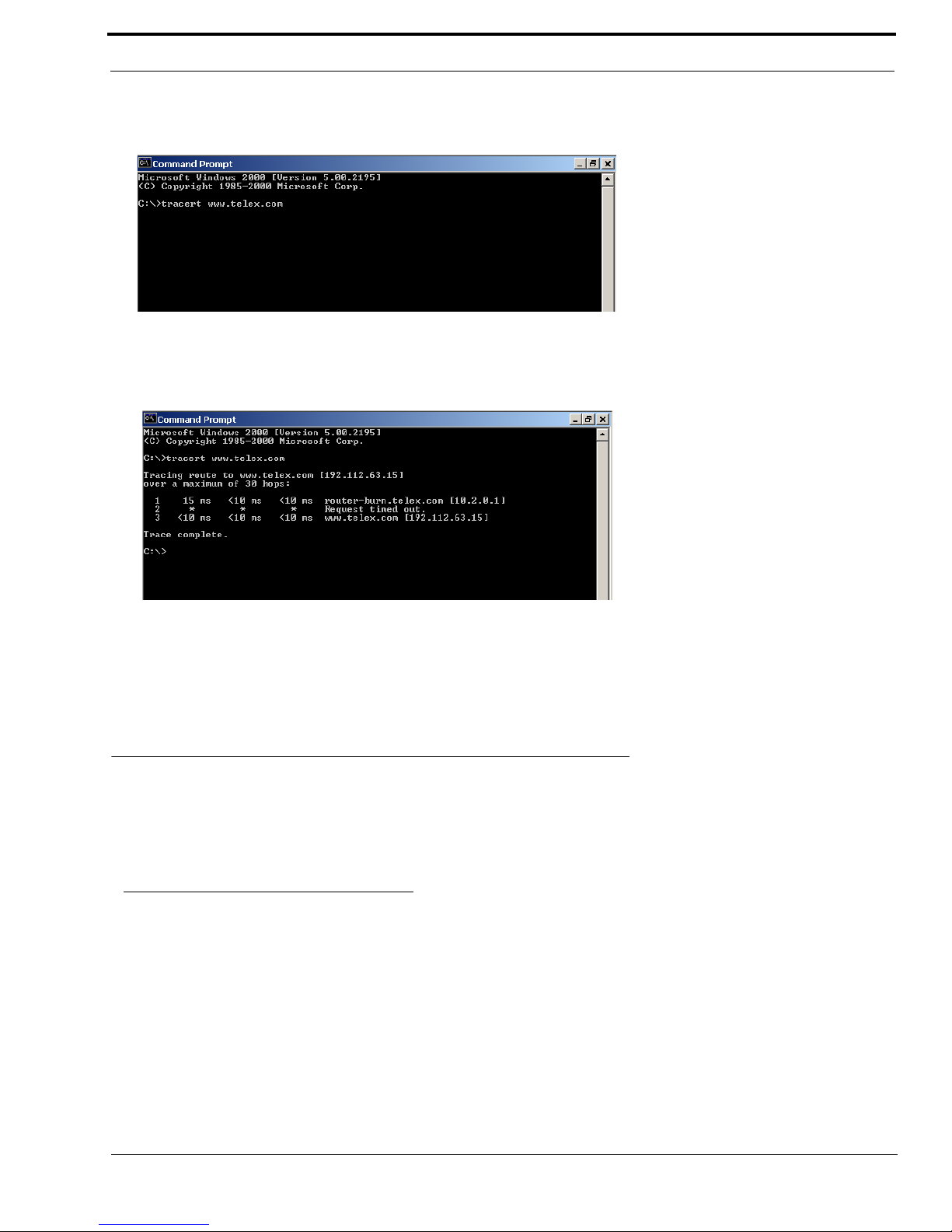
21
RVON Configuration
2. At the prompt, type tracert and type the url or IP Address you want to trace.
3. Press Enter.
The details of the tracer route are displayed.
NOTE: You will the message “request timed out” if the IP Address/ port IN or OUT is denied to the incoming or outgoing
message.
4. When you are finished, type exit to close the Command Prompt screen.
RVON Configuration
RVON cards use ports for communication of audio and control packets. Because routers can be configured to block certain
incoming and outgoing requests, you will need to open the following ports in your network to allow WAN connections to and
from a Network Interface Device. See Table X for the ports that need to be opened for the RVON cards to operate properly.
TABLE 4. Ports necessary for RVON card functionality.
Port Port Description
2076 UDP Call Control Signalling
2077 UDP Audio Packets
2079 UDP Telex Proprietary Signalling
2080 TCP Telex Keypanel Protocol
2081 UDP Pass Through Serial
2082 TCP Firmware Download
2100 Remote Administration
2102 Authentication Server
Page 26

Basic Network Configuration
22
Below, is an example of a router configuration screen. Not all routers are configured the same way and may not look exactly
like this screen.
NOTE: Linksys™ supports up to 253 nodes on a router. This is why it is called a Router/Switch because there are WAN
functions like a router as well as having a 4-port LAN switch. It also does not support simultaneous forward and DHCP.
Network Terminology
Bridges
A bridge is a device that connects two LANs, or two segments of the same LAN that use the same protocol.
Sometimes called “transparent bridges, they work at the OSI model Layer 2. Simply put, they are not
concerned with protocols. Their main job is to pass data to a destination address that is predetermined in the
data packet.
With a bridge, all of your computers are on the same network subnet (see Subnet). This means your
computers can communicate with each other and have their own Internet connection. If you assign your own
IP Addresses be sure to use the same first 3 “octets” of the IP Address (for example, 192.168.0.X).
Domain Name Server (DNS)
A DNS Server is an Internet service that translates domain names (for example, in the URL http://
www.telex.com, the domain name is the telex.com) into IP Addresses. The Internet is based on IP Addresses
which are numeric and since domain names are alphabetic, they are easier to remember. Every time a
domain name is used it must go through the DNS server to be translated into an IP Address.
Page 27

23
Network Terminology
Gateway
A gateway is a node on a network that serves as an entrance to another network. The gateway routes traffic
from a computer to an outside network that is serving the web pages. For example, the gateway for a home
computer is the ISP provider that connects the user to the Internet.
In a corporate environment, the gateway often acts as a proxy server and a firewall. Gateways are similar to
routers and switches in that they forward data to the destination and provide the path for which the data will
travel to the destination.
Hub
A hub is a common connection point for devices in a network. A hub has multiple ports. When a data packet
arrives at a hub, it is copied and distributed to all of its ports so that all nodes on the LAN can see the packets.
There are three types of hubs:
passive hub
- this hub serves as a conduit for the data, enabling it to go from one device to another.
intelligent hub (also known as manageable hubs) - this hub includes addition features that enable administrators
to monitor traffic through the hub.
switching hub - this hub reads the destination address of each packet and then forwards the data pack to the
appropriate port.
IP Address (Internet Protocol Address)
An IP Address is an identifier or numerical name for a computer or device on a network. Data between
computers are routed over the network using these addresses to identify the computer the message is being
sent to and the computer the message is being sent from.
The format of an IP Address is a 32-bit numeric address written as four numbers separated by periods. For
example, an IP Address looks like 10.100.1.1.
IMPORTANT: When working within an isolated network (meaning there is no Internet access), IP
Addresses can be assigned at random just as long as they are unique to each computer and device. When the
isolated network is connected to the Internet, registered Internet Addresses must be obtained. This is to
prevent duplication of addresses.
The four numbers in and IP Address are used in different was to identify a particular network and host on
that network. There are three classes of Internet Addresses.
CLASS A - supports 16 million hosts on each of 127 networks.
CLASS B - supports 65,000 hosts on each of 16,000 networks.
CLASS C - supports 254 hosts on each of 2 million networks.
LAN
A LAN is a computer network that connects a relatively small area (a single building or group of buildings).
Most LANs connect work stations and computers to each other. Each computer (also known as a “node”),
has its own processing unit and executes its own processing unit and executes its own programs; however it
can also access data and devices anywhere on the LAN. This means that many users can access and share the
same information and devices. A good example of a LAN device is a network printer. Most companies
cannot afford the budgetary or hardware expense of providing printers for each of its users; therefore, one
printer (i.e., device) is placed on the LAN where every user can access the same printer.
The LAN uses IP Addresses to route data to different destinations on the network. An IP Address is a 32-bit
numeric address written as four numbers separated by periods (for example 1.160.10.240).
Page 28

Basic Network Configuration
24
Port
A port, when referring to TCP and UDP networks, is an endpoint in a logical connection. The port number
identifies the type of port it is. For example, port 80 is used for HTTP traffic.
Routers
A router is a device that forwards data packets over networks. Most commonly, a router is connected to at
least two networks (normally LANs or WANs). Routers are located at gateways, the place where two
networks are connected. Routers do little data filtering, they mainly deliver the data.
Subnet
A subnet is a portion of a network that shares a common address component. On a TCP/IP network, a subnet
is described as all computers or devices whose IP Address have the same prefix.
Subnetting a network is useful because it provides security for the network as well as increases performance
of the network. IP networks are divided using subnet masks.
Switches
A switch is a device that filters and forwards data packets between networks. Switches operate at the data
layer, and sometimes at the network layer.
WA N
A wide area network connects two or more LANs and can span a relatively large geographical area. For
example, Telex Headquarters in Burnsville, MN is connected to several of its branch offices in Nebraska and
Arkansas over the wide area network. The largest WAN is the Internet.
Page 29

25
CHAPTER 5
Telnet & Serial Port Programming
RVON Serial and Telnet Commands
RVON card programming can be done via direct serial or telnet connection. There are several physical connections to an
RVON board:
• Direct serial through custom debug cable (J20 6-pin bottom front)
The customer debug cable always functions as the general-purpose debug tool.
• Backcard DB-9 J2
The backcard DB-(must be disabled/enabled via a DIP Switch because it can also be used for serial port pass-through. The
backcard DB-9 can be used for a debug terminal when DIP switch 6 is switched to the ON position.
• Backcard RJ-45 J1 (Telnet Only)
Setup
Serial Port 38,4000 baud, No-flow control
Telnet IP Address, port 23
Page 30

Telnet & Serial Port Programming
26
How to Configure the RVON-1 using Telnet
Without access to the physical KP-32 with RVON-1 installed on it, you can still configure the card through the use of Telnet.
The following instructions will show you how to access the Telnet screen and show you some of the information you can see
and edit.
NOTE: These instructions are to help you get to the Telnet screens and give you an overview of what can be done. This is
NOT an all inclusive document. Not every action that can be performed are contained within the document.
To Display the settings for the RVON-1 Card, do the following:
1. Open a command prompt.
2. At the prompt, type Tel ne t <IP ADDRESS> (The IP Address is the IP Address assigned to the RVON-1 card).
3. Press Enter.
The RVON logon screen appears.
4. In the logon field, type the RVON logon (default = telex).
5. Press Enter.
6. In the password field, type the RVON password (default = password).
Page 31

27
How to Configure the RVON-1 using Telnet
7. Press Enter.
A prompt appears.
8. Type dbgcmd to access the debug command screens.
9. Press Enter.
An MXP prompt appears.
10. At the prompt, type Show.
11. Press Enter.
The show commands screen and MXP prompt appears.
12. At the MXP prompt, type the show command you want to see (for example, “show rvon”).
13. Press Enter.
The values for the RVON-1 card appear.
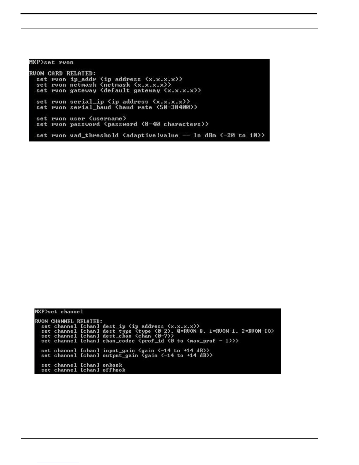
To edit the RVON-1 configuration, do the following:
1. Repeat steps 1 through 9 from above.
2. At the MXP prompt, type either set RVON or set EMAC (see screen descriptions below).
3. Press Enter.
Page 32
Telnet & Serial Port Programming
28
Note: This Telnet screen is almost duplicate to the right side of the Configuration screen for the RVON in AZedit.
set rvon ip_addr Allows you to edit the IP Address
set rvon netmask Allows you to edit the netmask
set rvon gateway Allows you to edit the gateway
set rvon serial_ip Allows you to edit the serial IP Address
set rvon serial_baud Allows you to set the baud rate (50-38400)
set rvon user
Allows you to set the username for the RVON-1 card. By default
the user name is “telex”
set rvon password
Allows you to set the password for the RVON-1 card. By default,
the password is “password”
set rvon vad_threshold
Lets you set the vad threshold.
NOTE: In AZedit, you can enable and disable VAD, however,
through Telnet you able to set the amount. You will able to set the
VAD threshold in later versions of AZedit.
set channel dest_ip
Allows you edit the destination IP Address the RVON-1 card will
communicate with
set channel dest_type
Allows you to edit the destination type for the device the RVON1 card will talk with
Page 33

29
How to Configure the RVON-1 using Telnet
set channel dest_channel
Allows you to edit the destination channel of the device the
RVON-1 will talk with
set channel channel_codec
Allow s you to e dit the C ODEC to be u sed for t ransfer ring the da ta
between the two devices
set channel input_gain Allows you to edit the input gain for the RVON-1 card
set channel output_gain Allows you to edit the output gain for the RVON-1 card.
set the channel onhook
onhook = hang up
If the channel was already connected, going offhook will have no
effect (it is already offhook if connected). Going onhook will
hang up the call, and it should then try to reconnect.
If the channel was not already connected, going offhook will
cause it to try and establish a connection. Going onhook in this
stat will have no effect (it is already onhook if idle.
set channel offhook
offhook = connected
If the channel was already connected, going offhook will have no
effect (it is already offhook if connected). Going onhook will
hang up the call, and it should then try to reconnect.
If the channel was not already connected, going offhook will
cause it to try and establish a connection. Going onhook in this
state will have no effect (it is already onhook).
Page 34

12000 Portland Avenue South • Burnsville, MN 55337 • U.S.A.
 Loading...