


 Loading...
DKP-3016 Keypanel
Technical Manual
up to and including version 1.2.6
DKP-3016 |
DKP-3016W |
F.01U.331.632 |
Rev. 01 |
06/2017 |
2 |
DKP-3016 |
PROPRIETARY NOTICE
The product information and design disclosed herein were originated by and are the property of Bosch Security Systems, Inc. Bosch reserves all patent, proprietary design, manufacturing, reproduction, use and sales rights thereto, and to any article disclosed therein, except to the extent rights are expressly granted to others.
COPYRIGHT NOTICE
Copyright 2017 by Bosch Security Systems, Inc. All rights reserved. Reproduction, in whole or in part, without prior written permission from Bosch is prohibited.
*All other trademarks are property of their respective owners.
WARRANTY AND SERVICE INFORMATION
For warranty and service information, refer to the appropriate web site below:
RTS Intercoms .............................. |
www.rtsintercoms.com/warranty |
RTS Digital |
|
RTSTW |
|
AudioCom |
|
RadioCom |
|
Intercom Headsets.................................................... |
www.telex.com |
CUSTOMER SUPPORT
Technical questions should be directed to:
Customer Service Department
Bosch Security Systems, Inc.
www.telex.com
TECHNICAL QUESTIONS EMEA
Bosch Security Systems Technical Support EMEA
http://www.rtsintercoms.com/contact_main.php
DISCLAIMER
The manufacturer of the equipment described herein makes no expressed or implied warranty with respect to anything contained in this manual and shall not be held liable for any implied warranties of fitness for a particular application or for any indirect, special, or consequential damages. The information contained herein is subject to change without prior notice and shall not be construed as an expressed or implied commitment on the part of the manufacturer.
THE LIGHTNING |
CAUTION: TO REDUCE |
THE EXCLAMATION |
|
FLASH AND |
|||
THE RISK OF ELECTRIC |
POINT WITHIN THE |
||
ARROWHEAD |
|||
SHOCK, DO NOT REMOVE |
TRIANGLE IS A |
||
WITHIN THE |
|||
COVER. NO USER- |
WARNING SIGN |
||
TRIANGLE IS A |
|||
SERVICABLE PARTS |
ALERTING YOU OF |
||
WARNING SIGN |
|||
INSIDE. REFER |
IMPORTANT |
||
ALERTING YOU OF |
|||
SERVICING TO |
INSTRUCTIONS |
||
“DANGEROUS |
|||
QUALIFIED SERVICE |
ACCOMPANYING |
||
VOLTAGE” INSIDE |
|||
PERSONNEL. |
THE PRODUCT. |
||
THE PRODUCT. |
|||
|
|
||
|
|
|
|
SEE MARKING ON |
BOTTOM/BACK OF PRODUCT. |
|
|
|
|
|
WARNING: APPARATUS SHALL NOT BE EXPOSED TO DRIPPING OR SPLASHING AND NO OBJECTS FILLED WITH LIQUIDS, SUCH AS VASES, SHALL BE PLACED ON THE APPARATUS.
WARNING: THE MAIN POWER PLUG MUST REMAIN READILY OPERABLE.
CAUTION: TO REDUCE THE RISK OF ELECTRIC SHOCK, GROUNDING OF THE CENTER PIN OF THIS PLUG MUST BE MAINTAINED.
WARNING: TO REDUCE THE RISK OF FIRE OR ELECTRIC SHOCK, DO NOT EXPOSE THIS APPRATUS TO RAIN OR MOISTURE.
WARNING: TO PREVENT INJURY, THIS APPARATUS MUST BE SECURELY ATTACHED TO THE FLOOR/WALL/RACK IN ACCORDANCE WITH THE INSTALLATION INSTRUCTIONS.
This product is AC only.
WARNING: THIS IS A CLASS A PRODUCT. IN A DOMESTIC ENVIRONMENT THIS PRODUCT MAY CAUSE RADIO INTERFERENCE, IN WHICH CASE THE USER MAY BE REQUIRED TO TAKE ADEQUATE MEASURES.
Bosch Security Systems, Inc. |
Technical Manual |
F.01U.331.632 |
Rev. 01 |

DKP-3016 |
3 |
|
|
Important Safety Instructions
1.Read these instructions.
2.Keep these instructions.
3.Heed all warnings.
4.Follow all instructions.
5.Do not use this apparatus near water.
6.Clean only with dry cloth.
7.Do not block any ventilation openings. Install in accordance with the manufacturer’s instructions.
8.Do not install near any heat sources such as radiators, heat registers, stoves, or other apparatus (including amplifiers) that produce heat.
9.Do not defeat the safety purpose of the polarized or grounding-type plug. A polarized plug has two blades with one wider than the other. A grounding type plug has two blades and a third grounding prong. The wide blade or the third prong are provided for your safety. If the provided plug does not fit into your outlet, consult an electrician for replacement of the obsolete outlet.
10.Protect the power cord from being walked on or pinched particularly at plugs, convenience receptacles, and the point where they exit from the apparatus.
11.Only use attachments/accessories specified by the manufacturer.
12.Use only with the cart, stand, tripod, bracket, or table specified by the manufacturer, or sold with the apparatus. When a cart is used, use caution when moving the cart/apparatus combination to avoid injury from tip-over.
13.Unplug this apparatus during lightning storms or when unused for long periods of time.
14.Refer all servicing to qualified service personnel. Servicing is required when the apparatus has been damaged in any way, such as power-supply cord or plug is damaged, liquid has been spilled or objects have fallen into the apparatus, the apparatus has been exposed to rain or moisture, does not operate normally, or has been dropped.
Bosch Security Systems, Inc. |
Technical Manual |
F.01U.331.632 |
Rev. 01 |

4 |
DKP-3016 |
|
|
|
|
Bosch Security Systems, Inc. |
Technical Manual |
F.01U.331.632 |
Rev. 01 |

Table |
|
of |
|
Contents |
|
INTRODUCTION ......................................................................................................................... |
9 |
Features .................................................................................................................................................... |
9 |
Specifications ......................................................................................................................................... |
10 |
DKP-3016 Block Diagram ..................................................................................................................... |
11 |
Reference View – DKP-3016 ................................................................................................................ |
12 |
Connector Pinouts .................................................................................................................................. |
13 |
INSTALLATION ........................................................................................................................ |
15 |
Requirements ......................................................................................................................................... |
15 |
DKP-3016 Installation ........................................................................................................................... |
16 |
Configuring the Keypanel Connection .................................................................................................. |
17 |
Power Up ................................................................................................................................................ |
19 |
Address Setting ...................................................................................................................................... |
20 |
Connections ............................................................................................................................................ |
21 |
BASIC OPERATION .................................................................................................................. |
23 |
Intercom Keys and Displays .................................................................................................................. |
23 |
Keypad Reference View ........................................................................................................................ |
26 |
INFO button ........................................................................................................................................... |
29 |
Breadcrumb Menu Navigation ............................................................................................................... |
30 |
Menu Navigation and shaft encoders ..................................................................................................... |
30 |
CLR Button ............................................................................................................................................ |
31 |
Basic Intercom Key Operation ............................................................................................................... |
31 |
Crosspoint Gain Adjustment .................................................................................................................. |
32 |
Keypanel Volume Adjustments ............................................................................................................. |
33 |
Aux Volume Adjustments ...................................................................................................................... |
35 |
Priority Call Volume Control ................................................................................................................. |
37 |
Operation of Intercom Keys with Auto Functions ................................................................................. |
39 |
Operation of Intercom Keys with Options ............................................................................................. |
40 |
Operation of Intercom Talk Keys with the Speaker DIM Setting ......................................................... |
40 |
Operation of Intercom Keys assigned to TIF Ports ................................................................................ |
41 |
User Quick Select Scrolling ................................................................................................................... |
41 |
Call Waiting Operation .......................................................................................................................... |
41 |
Graphical Call Waiting Window ............................................................................................................ |
42 |
Mic Select .............................................................................................................................................. |
45 |
Setup Pages ............................................................................................................................................ |
47 |
Menu Passwords .................................................................................................................................... |
47 |
Bosch Security Systems, Inc. |
Technical Manual |
F.01U.331.632 |
Rev. 01 |

6 |
DKP-3016 |
|
|
|
|
|
Keypanel Color Window ....................................................................................................................... |
48 |
|
Enhanced Tallies ................................................................................................................................... |
55 |
|
Flash Text Characteristics Window ...................................................................................................... |
59 |
|
Show Icon Characteristics Window ...................................................................................................... |
61 |
FIRMWARE DOWNLOAD ....................................................................................................... |
65 |
Download Firmware to the DKP-3016 From AZedit ........................................................................... |
65 |
Download Firmware to the Keypanel Using the Firmware Upload Tool ............................................. |
68 |
Download Firmware Using the Bootloader .......................................................................................... |
70 |
Display the Bootloader Version from the Keypanel ............................................................................. |
72 |
Download and Upgrade the Bootloader in the DKP-3016 .................................................................... |
72 |
Display the FPGA Version .................................................................................................................... |
74 |
Download and Upgrade the FPGA in the DKP-3016 ........................................................................... |
74 |
Download a Font File ............................................................................................................................ |
77 |
DKP-3016 MENU SYSTEM ...................................................................................................... |
81 |
Main Menu Access ................................................................................................................................ |
81 |
Menu System, Audio Options ............................................................................................................... |
82 |
Menu System, Display ........................................................................................................................ |
101 |
Menu System, Key Assign Menu ........................................................................................................ |
105 |
Menu System, Key Options Menu ...................................................................................................... |
110 |
Menu System, OMNEO Offers ........................................................................................................... |
115 |
Menu System, RVON Offers (Only available when an RVON-IO is detected) ................................. |
116 |
Menu System, Save Config ................................................................................................................. |
116 |
Menu System, Service ......................................................................................................................... |
117 |
TELEPHONE INTERFACE (TIF) OPERATION ................................................................ |
133 |
Receiving A Phone Call ...................................................................................................................... |
133 |
Hanging Up ......................................................................................................................................... |
133 |
KEYPANEL MENU QUICK REFERENCE .......................................................................... |
135 |
Audio Options ..................................................................................................................................... |
135 |
Display Menu ...................................................................................................................................... |
141 |
Key Assign Menu ................................................................................................................................ |
142 |
Key Options Menu .............................................................................................................................. |
143 |
OMNEO Offers Menu ......................................................................................................................... |
145 |
RVON Offers Menu ............................................................................................................................ |
145 |
Save Config Menu ............................................................................................................................... |
145 |
Service Menu ....................................................................................................................................... |
146 |
Unicode Support ........................................................................................................................ |
149 |
AZedit and Unicode Support ............................................................................................................... |
149 |
Wall Mounting Option .............................................................................................................. |
153 |
Wall Mount Instructions ...................................................................................................................... |
153 |
Bosch Security Systems, Inc. |
Technical Manual |
F.01U.331.632 |
Rev. 01 |

|
List |
|
|
of |
|
|
Figures |
|
FIGURE 1. |
DKP-3016 Audio Flow Block Diagram ........................................................................... |
11 |
FIGURE 2. |
DKP-3016 Reference View .............................................................................................. |
12 |
FIGURE 3. |
DKP-3016 Installation ...................................................................................................... |
16 |
FIGURE 4. |
DKP-3016 Keypad ............................................................................................................ |
26 |
FIGURE 5. |
Breadcrumb Navigation .................................................................................................... |
30 |
FIGURE 6. |
DKP-3016 shaft encoders ................................................................................................. |
30 |
FIGURE 7. |
Key Function Position Explanation .................................................................................. |
31 |
FIGURE 8. |
Talk/Listen Indicators ....................................................................................................... |
32 |
FIGURE 9. |
Incoming Priority Call Volume Control Keypanel ........................................................... |
37 |
FIGURE 10. |
Graphical Call Waiting Window ...................................................................................... |
42 |
FIGURE 11. |
Graphical Call Waiting Window Highlighted Call ........................................................... |
43 |
FIGURE 12. |
Keypanel Colors Window ................................................................................................. |
48 |
FIGURE 13. |
Color Grid ......................................................................................................................... |
50 |
FIGURE 14. |
Key Assignments Page ..................................................................................................... |
51 |
FIGURE 15. |
Assignments Groups Page ................................................................................................ |
52 |
FIGURE 16. |
Miscellaneous Colors Page ............................................................................................... |
54 |
FIGURE 17. |
Flash Text Characteristics Window .................................................................................. |
59 |
FIGURE 18. |
Show Icon Characteristic Window ................................................................................... |
61 |
FIGURE 19. |
Automatic Gain Control Example .................................................................................... |
83 |
Bosch Security Systems, Inc. |
Technical Manual |
F.01U.331.632 |
Rev. 01 |

8 |
DKP-3016 |
|
|
|
|
Bosch Security Systems, Inc. |
Technical Manual |
F.01U.331.632 |
Rev. 01 |

CHAPTER 1
Introduction
The DKP-3016 delivers superior high-quality digital audio using OMNEO technology from Bosch with Dante audio over IP via copper. It delivers audio free of noise, delay, and other artifacts present in legacy technology.
The DKP-3016 utilizes the latest generation of wide angle TFT displays, providing superior clarity, resolution, and longer display life, and delivering high-quality readability under a variety of lighting conditions.
Features
•Superior digital, high-quality audio over IP (Internet Protocol) included through OMNEO technology, the branded IPbased solution from Bosch.
•Advanced signal processing, delivering an audio experience, free of noise, echo, delay, and other artifacts present in legacy technology.
•Backward compatible with legacy technologies, such as analog audio in USOC and 568-B formats.
•New wide angle, high-definition display.
•Enhanced keypanel menus optimized for ease of use.
Bosch Security Systems, Inc. |
Technical Manual |
F.01U.331.632 |
Rev. 01 |

10 Introduction |
DKP-3016 |
Specifications
LCD Display:
Active Area ................ |
120.10mm (wide) x 35.86 mm (high) |
Dot Resolution.............................................. |
576 x 172 pixels |
Color Resolution .............................. |
16-bit (64K) RGB color |
View Angle....................... |
80 degrees (typical; all directions) |
Power Supply:
Type:............................................................................. |
Internal |
AC Input:............................................. |
100–240VAC 50/60Hz |
Inputs:
Matrix
Type ........................................................................... |
Balanced |
Typical Input Level ...................................................... |
+8 dBu |
Typical Input Impedance................................................ |
20 kΩ |
Maximum Input Level................................................ |
+20 dBu |
Supported Bandwidth................................... |
100 Hz to 20 kHz |
Front Panel Mic |
|
Type .............................................................................. |
Electret |
Typical Input Level ..................................................... |
-42 dBu |
Typical Input Impedance................................................. |
.1 kΩ |
Maximum Input Level................................................. |
-25 dBu |
Left and Right Headset Mic - Electret |
|
Typical Input Level ..................................................... |
-42 dBu |
Typical Input Impedance.................................................. |
1 kΩ |
Maximum Input Level................................................. |
-25 dBu |
Left and Right Headset Mic - Dynamic |
|
Typical Input Level ..................................................... |
-50 dBu |
Typical Input Impedance................................................ |
600 Ω |
Maximum Input Level................................................. |
-25 dBu |
Outputs:
Matrix
Type ........................................................................... |
Balanced |
Typical Output Level.................................................... |
+8 dBu |
THD+N% .................................................................... |
<0.20% |
Typical Output Impedance ............................................. |
600 Ω |
Maximum Output Level ............................................. |
+20 dBu |
Frequency Response..................................... |
100 Hz to 20 kHz |
Headset - Left, Right |
|
Maximum |
|
Output Power ....................................... |
125 mW for 32 Ω load |
Earphone Impedance ...................................... |
16 Ω and above |
THD+N%..................................................................... |
<0.20% |
Frequency Response ...................................... |
20 Hz to 20 kHz |
Digital:
OMNEO Channels
Typical OMNEO Latency |
................................................. 1 ms |
Frequency Response ...................................... |
20 Hz to 20 kHz |
Environmental:
Dimensions DKP-3016/3016W
3.60 in. H x 10.63 in. W x 9.35 in. D
(91.5 mm H x 270.1 mm W x 237.6 mm D)
Weight |
|
DKP-3016/3016W |
........................................3.59 lb. (1.63 kg) |
Temperature |
|
Operating ............................... |
0° C to 50° C (32° F to 131° F) |
Storage ................................. |
- 20° C to 70° C (-4° F to 158° F) |
Power Consumption:
DKP-3016/3016W
Nominal ...................................................................... |
13 Watts |
Maximum.................................................................... |
17 Watts |
Maximum Volt Amp ...................................................... |
42 VA |
Certification:
CE Compliance
EMC
•EN55032 Class A
•VCCI Class A
•ICES-003 Class A
•FCC Part 15 Subpart B Class A
•AS/NZS CISPR32 Class A
•Korean KN 32 Class A
•BSMI Class A
•EN 55024
•Korean KN 35
Safety
•UL 60950-1
•EN60950-1
•CB Report
•PSE
Bosch Security Systems, Inc. |
Technical Manual |
F.01U.331.632 |
Rev. 01 |

DKP-3016 |
Introduction 11 |
DKP-3016 Block Diagram
FIGURE 1. DKP-3016 Audio Flow Block Diagram
Bosch Security Systems, Inc. |
Technical Manual |
F.01U.331.632 |
Rev. 01 |
12 Introduction |
DKP-3016 |
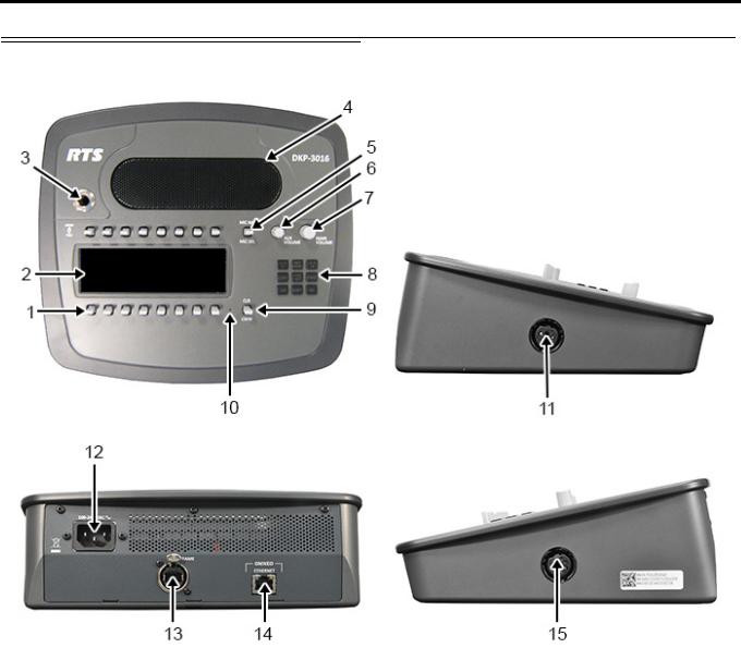
Reference View – DKP-3016
FIGURE 2. DKP-3016 Reference View |
|
|
|
1. |
Talk/Listen Lever Keys |
9. |
CLR/CWW Lever Key |
2. |
LCD Display |
10. |
User Reset Hole |
3. |
Microphone Connector |
11. |
4-pin Headset Connector |
4. |
Front Speaker |
12. |
AC Power |
5. |
MIC MUTE/MIC SEL Lever Key |
13. |
FRAME Connector |
6. |
AUX VOLUME shaft encoder |
14. |
OMNEO ETHERNET Connector |
7. |
MAIN VOLUME shaft encoder |
15. |
5-pin Headset Connector |
8.Keypad
Bosch Security Systems, Inc. |
Technical Manual |
F.01U.331.632 |
Rev. 01 |
DKP-3016 |
Introduction 13 |
Connector Pinouts
Right Headset: J5 (Wallmount version – J15)
Pin |
Assignment |
1RIGHT_HS_MIC_IN -
2RIGHT_HS_MIC_IN +
3RIGHT_HS_COMMON
4RIGHT_HS_L_OUT
5RIGHT_HS_R_OUT
Left Headset: J15 (Wallmount version – J5)
Pin |
Assignment |
1LEFT_HS_MIC_IN -
2LEFT_HS_MIC_IN +
3LEFT_HS_COMMON
4LEFT_HS_L_OUT
Matrix Connector: J8a
|
Pin |
RJ-45 |
RJ-12 |
|
|
|
|
|
|
1 |
RS485 + |
|
||
2 |
RS485 - |
RS485 - |
||
3 |
FROM MATRIX + |
FROM MATRIX + |
||
4 |
TO MATRIX + |
TO MATRIX + |
||
5 |
TO MATRIX - |
TO MATRIX - |
||
6 |
FROM MATRIX - |
FROM MATRIX - |
||
7 |
RS485 + |
RS485 + |
||
8 |
RS485- |
|
||
|
|
|
|
|
a.Supports 568B and USOC wiring
ETHERNET: J11
Pin |
|
Assignment |
|
|
|
1 |
Data 1 + |
|
2 |
Data 1 |
- |
3 |
Data 2 |
+ |
4 |
Data 3 |
+ |
5 |
Data 3 |
- |
6 |
Data 2- |
|
7 |
Data 4+ |
|
8 |
Data 4- |
|
|
Front Panel Mic |
|
|
|
|
Pin |
|
Assignment |
|
|
|
Tip |
|
PANEL_MIC_IN + |
Ring |
|
PANEL_MIC_IN - |
Sleeve |
|
CGND |
Bosch Security Systems, Inc. |
Technical Manual |
F.01U.331.632 |
Rev. 01 |

14 Introduction |
DKP-3016 |
|
|
|
|
Bosch Security Systems, Inc. |
Technical Manual |
F.01U.331.632 |
Rev. 01 |

CHAPTER 2
Installation
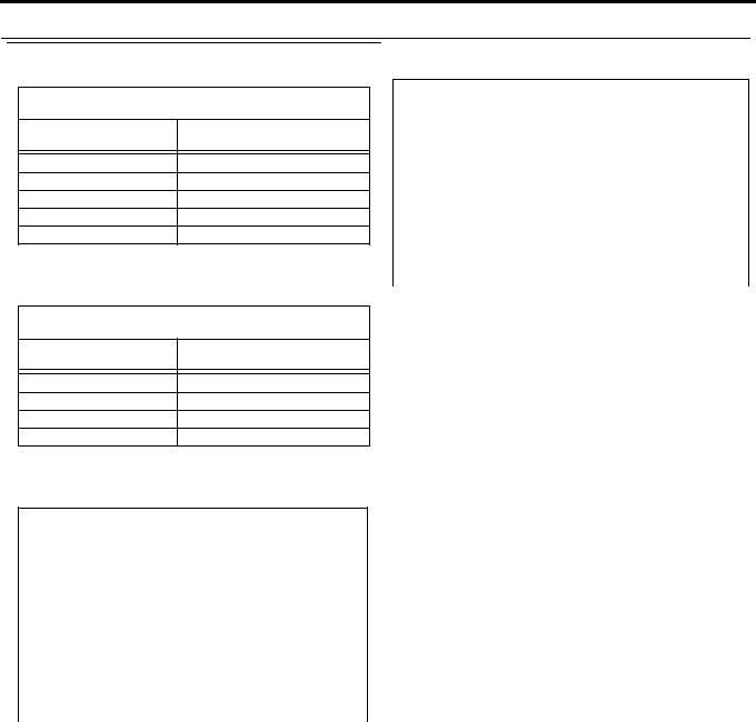
Requirements
The following keypanel firmware versions are needed for the specified DKP-3016 model:
AZedit................. |
V5.2.2 or later |
IPedit.................. |
V3.2.3 or later |
MCII-e................ |
V3.4.0 or later |
AIO-16................ |
V1.7.0 or later |
FWUT................. |
V4.20.3586 or later |
DNS-SD.............. |
V4.20.3586 or later |
OMI .................... |
V6.1.8 or later |
Bosch Security Systems, Inc. |
Technical Manual |
F.01U.331.632 |
Rev. 01 |
16 Installation |
DKP-3016 |
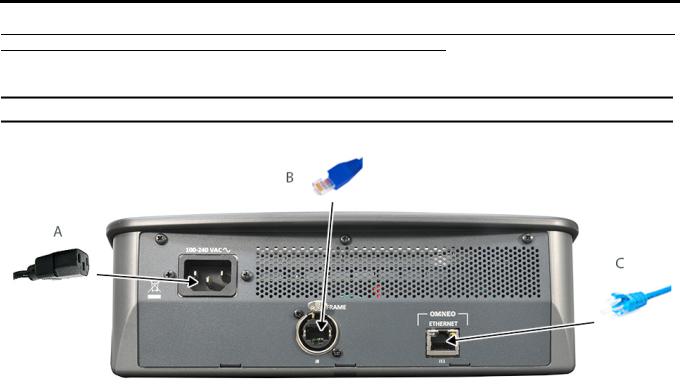
DKP-3016 Installation
IMPORTANT: For DKP-3016 wall mounting instructions, see “Wall Mounting Option” on page 275.
FIGURE 3. DKP-3016 Installation
To install the DKP-3016, do the following:
1.On the rear panel of the DKP-3016, plug the AC power cord (A) into the power connector on the back panel of the unit.
2.Connect an RJ-12 or RJ-45 (USOC or 568B) cable (B) with RTS cabling to the J8 FRAME connector. OR
Connect a CAT-5e cable (C) to the J11 ETHERNET connector.
NOTE: The KP-Series panels can have both AIO and Ethernet connected simultaneously, and the user can switch between connections using the menus.
3.Once the unit is cabled, plug the AC power cord into the wall outlet or a power strip.
Bosch Security Systems, Inc. |
Technical Manual |
F.01U.331.632 |
Rev. 01 |

DKP-3016 |
Installation 17 |
Configuring the Keypanel Connection
You can configure the OMI using AZedit and IPedit; however, only IPedit can be used to configure the keypanel.
Configure the OMI using AZedit
To connect the OMI to the DKP-3016 using AZedit, do the following:
1.From the Status menu in AZedit, select I/O Cards.
The I/O Card Status window appears showing a list of installed cards.
2.Right-click the OMI card you want to connect to the keypanel.
A pop-up menu appears.
3.From the pop-up menu, select OMNEO Configuration.
The OMNEO Configuration window appears.
4.From the OMNEO card drop down menu, select the slot number where the OMI card is located in the frame.
The Device Name field auto-populates with the name of the device.
5.From the Local Channel drop down menu, select the channel you want to use to communicate to your keypanel across the network.
NOTE: Channels not already configured to connect to another device appear with an asterisk (*) next to them.
6.In the Partner Device Name field, enter the name of keypanel you want to use to communicate with. Or, select the Browse icon to select from a list of devices.
7.From the Partner Device Type drop down menu, select the type of device to which the OMI card is connecting.
8.From the Partner Channel drop down menu, select channel 1 on the device to which the OMI communicates.
9.Once you are completely finished, click Apply.
Apply sends the changes to the cards in the intercom, or Click Cancel to discard all the changes made.
Add the OMI to the Device Catalog in IPedit
To add the keypanel to IPedit, do the following:
1.Open IPedit.
2.From the Device menu, select Add.
The Add Devices Window appears, open to the Search tab.
3.Select the OMI card.
The Add button becomes active.
4.Click the Add button.
The OMI card appears in the device catalog in the left panel.
5.Click the Done button.
The Add Devices window closes.
Add the DKP-3016 to the Device Catalog in IPedit
To add the keypanel to IPedit, do the following:
1.Open IPedit.
2.From the Device menu, select Add.
The Add Devices Window appears, open to the Search tab.
3.Select the keypanel.
The Add button becomes active.
4.Click the Add button.
The keypanel appears in the device catalog in the left panel.
5.Click the Done button.
The Add Devices window closes.
Bosch Security Systems, Inc. |
Technical Manual |
F.01U.331.632 |
Rev. 01 |

18 Installation |
DKP-3016 |
Configure the OMI using IPedit
To configure the OMI using IPedit, do the following:
Using the Device Configuration and Status Pane
1.In the Device Name field, enter a device name familiar to you, if desired.
Initially OMI cards are given a default name.
IMPORTANT: If you change the device name, this causes the device to reboot. It is not necessary to change the device name. However, if you do change the name, it is best to do this early in the setup so you do not have to revisit other devices that connect to this device and update them later.
2. In the Description field, enter a description for the OMI card, if desired.
Using the Channel Configuration and Status Section:
3.In the Channel Description field, enter a channel description, if applicable.
4.From the Destination Type drop down menu, select OKP.
5.In the Destination Device Name field, enter the name of the device to which the channel will connect. OR
a.Click the ... button.
The Discovered Devices Window appears.
b.Expand the tree to view the available devices.
c.From the expanded tree, select the device to which you want to connect.
d.Click OK.
6.From the Destination Channel drop down menu, select the channel to which the OMI will connect.
7.Send the changes to the OMI.
Configure the DKP-3016 using IPedit
To configure the keypanel using IPedit, do the following:
Using the Device Configuration and Status Pane
1.In the Device Name field, enter a device name familiar to you, if desired.
Initially, keypanels are given a default name.
IMPORTANT: If you change the device name, this causes the device to reboot. It is not necessary to change the device name. However, if you do change the name, it is best to do this early in the setup so you do not have to revisit other devices that connect to this device and update them later.
2. In the Description field, enter a description for the keypanel, if desired.
Using the Channel Configuration and Status Section:
3.In the Channel Description field, enter a channel description, if applicable.
4.From the Destination Type drop down menu, select OMI.
5.In the Destination Device Name field, enter the name of the device to which the channel will connect. OR
a.Click the... button.
The Discovered Devices Window appears.
b.Expand the tree to view the available devices.
c.From the expanded tree, select the device to which you want to connect this keypanel.
d.Click OK.
Bosch Security Systems, Inc. |
Technical Manual |
F.01U.331.632 |
Rev. 01 |

DKP-3016 |
Installation 19 |
6.From the Destination Channel drop down menu, select the channel to which this keypanel will connect.
7.Send the changes to the keypanel.
Connecting the DKP-3016 through the OMNEO Offers Menu
IMPORTANT: If you used IPedit to set up the keypanel connection, this step not needed, because you have already done this in the software.
If you used AZedit to set up the keypanel connection, the keypanel needs to be set up to talk with the OMI card in the frame. To do this, a connection needs to be established using the OMNEO Offers menu on the keypanel. For more information, see “Menu System, OMNEO Offers” on page 115.
To configure a connection offer, do the following:
1.Starting at the OMNEO Offers | Keypanel menu, select OKP.
2.Press the SEL button.
A list of available OMNEO offers appears.
3.Using the AUX VOLUME shaft encoder, select the OMNEO offer you want to use.
An arrow appears next to the device.
4.Press the CLR button to exit menu mode.
Power Up
At power-up, if the keypanel is connected to the matrix, the alphanumeric display shows dashes in the light blue color key
 . After several seconds, the intercom key assignments are shown with the appropriate color keys and alphas.
NOTE: If the keypanel cannot establish communications with the intercom system, all keys continue to show asterisks
(****) and the Disconnected from Matrix icon  appears in the panel display. If the keypanel is configured for OMNEO, this icon also displays the OMNEO device name. Check the keypanel to matrix cable connection if this occurs. If the keypanel loses communications with the intercom, the panel display shows the
Disconnected from Matrix icon and displays the  after approximately 30 seconds.
Bosch Security Systems, Inc. |
Technical Manual |
F.01U.331.632 |
Rev. 01 |

20 Installation |
DKP-3016 |
Address Setting
General Information
In ADAM intercoms using AIO-8 cards or AIO-16 cards with SCSI breakouts, and in ADAM-CS and Zeus/Zeus II intercoms, the intercom ports share data connections in groups of eight (8). Each keypanel is uniquely identified on the data port by its address. The method of determining the proper address varies for each intercom system. Use the method for your intercom system, as described on the following pages.
TABLE 1. DKP-3016 Addressing
|
Manually Addressed |
|
Automatically Addressed |
|
|
|
|||
You must manually addressa the keypanel when using the |
The keypanel address is automatically detected when using |
|||
following: |
|
the following: |
||
• AIO-8 on ADAM |
• |
AIO-16 MDR on ADAM and ADAM-M |
||
• AIO-16 SCSI on ADAM |
• |
Cronus |
||
• |
ADAM CS |
• |
Zeus III and Zeus III LE/LE+ |
|
• |
Zeus I |
• |
RVON Products - RVON-8, RVON-2, |
|
• |
Zeus II |
|
RVON-C, and RVON-16 |
|
• |
OMNEO devices |
|||
|
|
|||
|
|
NOTE: |
Keypanels using RVON-I/O may need to be |
|
|
|
|
individually addressed. See the RVON-I/O user |
|
|
|
|
manual for further instruction. |
|
a. To manually address the DKP-3016, see “Service Menu, Set Address” on page 130.
To see specific addressing information for:
•ADAM with AIO-8 cards, see the ADAM technical manual (P/N F01U216986).
•ADAM CS, see the ADAM CS technical manual (P/N 93307517000).
•ADAM and ADAM-M with AIO-16 cards, see the AIO-16 user manual (P/N F01U193267).
•Cronus, see Cronus user manual (P/N F01U118890).
•Zeus III, see the Zeus III user manual (P/N F01U193289).
•Zeus III LE/LE+, see the Zeus III LE/LE+ user manual (P/N F01U193290).
NOTE: If you are connecting to an ADAM or ADAM-M frame with AIO-16 cards using MDR connectors or a Cronus frame, you do not need to set the address. If the AIO-16 is using SCSI breakouts, you must set the address.
Bosch Security Systems, Inc. |
Technical Manual |
F.01U.331.632 |
Rev. 01 |
DKP-3016 |
Installation 21 |
Connections
Frame Connector
Use the Frame connector to connect to an intercom port of the intercom system. For the frame connector location, see Figure 3 on page 15. The intercom port you connect to should agree with the address you set previously.
Ethernet Connector
Use the Ethernet connector to connect the keypanel to a network system. Each
RJ-45 Ethernet connector has two LEDs:
Right LED. The left LED is yellow and indicates a network link is established. It flashes on/off whenever there is network activity.
Left LED. The right LED is bi-color (orange and green) and indicates the speed of the connection by the color that is displayed.
•A green LED indicates the port is operating at 1000Mbps (1 Gbps).
•An orange LED indicates the port is operating at 100Mbps.
•No LED color indicates the port is operating at 10Mbps. This is not suitable for OMNEO networking.
Panel Microphone Connector
A panel microphone may be connected to the front of the unit. The connector accepts MCP5, MCP6, or MCP90 series panel microphones. Insert the microphone and rotate the entire microphone body clockwise several turns to lock it in place.
Bosch Security Systems, Inc. |
Technical Manual |
F.01U.331.632 |
Rev. 01 |

22 Installation |
DKP-3016 |
|
|
|
|
Bosch Security Systems, Inc. |
Technical Manual |
F.01U.331.632 |
Rev. 01 |

CHAPTER 3
Basic Operation
Intercom Keys and Displays
Color Display Descriptions for Intercom Keys
The DKP-3016 display uses key colors to distinguish the type of key assignment programmed on each key. Use Table 2 to help you determine the available key assignment colors.
You can customize these colors to your preference by using the “Keypanel Color Window” on page 48. TABLE 2. Default Key Colors
Default Color |
Description |
|||
|
|
|
Bright Green |
Listen Indicator, Local Matrix |
|
|
|
|
|
|
|
|
Brown |
IFB Special List |
|
|
|
|
|
|
|
|
Teal |
Point-to-Point |
|
|
|
|
|
|
|
|
Dark Yellow |
ISO |
|
|
|
||
|
|
|
|
|
|
|
|
Light Blue |
Unassigned, Test Mode (with Talk and Listen Indicators) |
|
|
|
|
|
|
|
|
Pale Yellow |
Special Functions |
|
|
|
|
|
|
|
|
Magenta |
Relay |
|
|
|
|
|
|
|
|
Pink |
Party Line |
|
|
|
|
|
|
|
|
Red |
Remote Matrix |
|
|
|
|
|
|
|
|
Salmon |
IFB, Talk Indicator |
|
|
|
|
|
|
|
|
Pale Green |
Special List |
|
|
|
|
|
|
|
|
Periwinkle |
UPL Resource |
|
|
|
|
|
Bosch Security Systems, Inc. |
Technical Manual |
F.01U.331.632 |
Rev. 01 |
24 Basic Operation |
DKP-3016 |
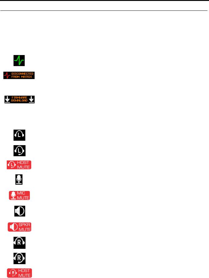
Display Icons
Display Icons are used to indicate the accessories and features enabled, disabled, active, and inactive. Use Table 3 for a complete description of each icon seen on the DKP-3016.
TABLE 3. Display Icon Descriptions
Icon |
Icon Name |
Description |
|
|
|
|
|
|
|
Matrix Connected |
The keypanel is connected to the Matrix. This icon briefly displays at connection. |
|
|
|
|
|
|
Disconnected From |
There is no connection between the Matrix and the keypanel. This icon is displayed as long as |
|
|
Matrix |
there is no Matrix data connection. |
|
|
|
NOTE: When the keypanel is disconnected, it displays its Device Name (for OMNEO) or IP |
|
|
|
|
|
|
|
Address (for RVON) device connections. |
|
|
|
|
|
|
Firmware |
Firmware is being downloaded to the keypanel. A progress bar at the bottom displays: |
|
|
Download |
chunk progress |
|
|
|
overall progress |
|
|
|
chunk/overall progress |
|
|
|
NOTE: For more information, see “Download Firmware to the DKP-3016 From AZedit” on |
|
|
|
page 65. |
|
|
Left Headphones |
The left headphones are enabled. This indicates the left headset microphone is not enabled. |
|
|
|
|
|
|
Left Headset |
The left headset is enabled. |
|
|
|
To enable the headset, see “Audio Options Menu, Headset Speaker” on page 94. |
|
|
|
|
|
|
Left Headset Mic |
The left headset mic is muted. |
|
|
Muted |
|
|
|
|
|
|
|
Microphone |
The microphone is enabled. |
|
|
|
|
|
|
Microphone Mute |
The microphone is muted. |
|
|
|
To mute the microphone, see “Audio Options Menu, Mic Mute” on page 98. |
|
|
|
To mute the headset mic, see “Audio Options Menu, Headset Mic” on page 93 |
|
|
|
|
|
|
Speaker |
The speaker is enabled. |
|
|
|
To enable the speaker, see “Audio Options Menu, Speaker” on page 100. |
|
|
|
|
|
|
Speaker Mute |
The speaker is muted. |
|
|
|
|
|
|
Right Headphones |
The right headphones are enabled. This indicates the right headset microphone is not enabled. |
|
|
|
|
|
|
Right Headset |
The right headset is enabled. |
|
|
|
To enable the headset, see “Audio Options Menu, Headset Speaker” on page 94. |
|
|
|
|
|
|
Right Headset Mic |
The right headset mic is muted. |
|
|
Muted |
|
|
|
|
|
Bosch Security Systems, Inc. |
Technical Manual |
F.01U.331.632 |
Rev. 01 |
DKP-3016 Basic Operation 25
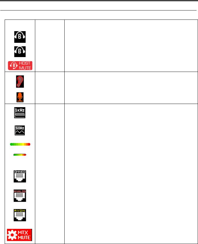
TABLE 3. Display Icon Descriptions
Icon |
Icon Name |
Description |
|
|
|
|
Both Headphones |
Both right and left headphones are enabled. This indicates both the right and left headset mics |
|
|
are disabled. |
|
|
|
|
Both Headsets |
Both right and left headsets are active. |
|
|
|
|
Both Headsets |
Both right and left headset mics are muted. |
|
Muted |
|
Snoop Tally Active Snoop Tally is Active on the keypanel.
|
You must have the Hot Mic enabled to use snoop tallies. |
|
To enable snoop tallies, see “Service Menu, Snoop Tally” on page 130. |
|
|
Hot Mic |
The hot mic is active. |
|
To activate Hot Mic, see “Audio Options Menu, Matrix Out” on page 97. |
Tone 1kHz Enabled Tone 1kHz is enabled on the keypanel.
|
To enable tone 1kHz, see “Audio Options Menu, Tone Gen” on page 100. |
|
|
Tone 500Hz |
Tone 500Hz is enabled on the keypanel. |
Enabled |
To enable tone 500Hz, see “Audio Options Menu, Tone Gen” on page 100. |
|
|
Main Volume Bar |
The main volume bar is used to control the volume for the keypanel inputs and outputs, |
|
including all speaker and headset outputs, and matrix inputs. |
Key Volume Bar |
The key volume bar is used to control the listen gain on a per key level. The listen gain range is |
|
+6dB to -80db, or Mute. |
|
NOTE: Listen must be assigned on the key assignment for this function to operate. |
|
|
OMNEO Enabled |
The OMNEO matrix interface is enabled on the panel. For more information on OMNEO |
|
Offers, see “Menu System, OMNEO Offers” on page 115. |
|
|
AIO Enabled |
The AIO matrix interface is enabled on the panel. For more information on AIO connection |
|
configuration, see “Menu System, OMNEO Offers” on page 115. |
|
|
RVON Enabled |
The RVON matrix interface is enabled on the panel. For more information on RVON Offers, |
|
see “Menu System, RVON Offers (Only available when an RVON-IO is detected)” on |
|
page 116. |
|
|
Matrix Input Mute |
The Matrix Input volume is muted. When the Matrix Input volume is adjusted down to Mute, |
|
the panel displays this flashing icon as a warning that there is no audio from the Matrix. |
Bosch Security Systems, Inc. |
Technical Manual |
F.01U.331.632 |
Rev. 01 |
26 Basic Operation |
DKP-3016 |
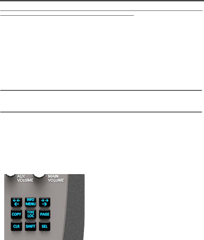
Keypad Reference View
There are two tiers available on the DKP 3016’s keypad: Primary Mode and SHIFT Mode.
Primary Mode
Primary Mode is used for the most common keypanel functions, such as CLR, SEL, COPY, PAGE, LEFT/RIGHT and accessing the Main menu. There are no special keypad sequences to use these functions.
Shift Mode
SHIFT Mode contains secondary functions used to access more functionality. The SHIFT mode functions are located above the primary keypad key. The shift functions available; INFO, PAGE LEFT/PAGE RIGHT, SHIFT COPY, SHIFT PAGE, and TYPE.
IMPORTANT: When SHIFT + <keypad key> appears in this manual, the user is instructed to press the SHIFT key followed by the next keypad key. The SHIFT key and the keypad key should not be pressed simultaneously.
If the user is instructed to press two keys simultaneously, this manual uses the phrase press and hold.
NOTE: By default, the keypad backlight changes to white when the keypad is in SHIFT mode. For more information, see “Service Menu, Keypad” on page 121.
To access Shift Mode, do the following:
1.On the keypad, press the SHIFT button.
2.On the keypad, press the key whose SHIFT function you want to access.
NOTE: Once you enter SHIFT mode, you can exit the mode by pressing the SHIFT key again, without pressing any other keys.
FIGURE 4. DKP-3016 Keypad
Bosch Security Systems, Inc. |
Technical Manual |
F.01U.331.632 |
Rev. 01 |

DKP-3016 |
|
Basic Operation 27 |
||
|
|
|
|
|
|
TABLE 4. |
|
|
|
|
|
|
|
|
|
Keypad |
Shift |
Description |
|
|
Button |
Function |
||
|
|
|
||
|
LOC |
TYPE |
The LOC/TYPE button displays the list of available intercoms (LOCations) available to scroll |
|
|
from. Select an intercom name to access the scroll lists for that intercom. |
|||
|
|
|
||
|
|
|
The TYPE button displays the keypanel assignment types available for scrolling. |
|
|
|
|
The button moves you backwards through the menu options or available key assignments |
|
|
|
|
one at a time or by the page. |
|
|
MENU |
INFO |
The MENU/INFO button is used to access the top level menu structure or access a secondary |
|
|
menu of commonly used features (see, “INFO button” on page 29). |
|||
|
|
|
||
|
|
|
The MENU button is used to access the top-level menu structure. |
|
|
|
|
> Press the Menu button once. |
|
|
|
|
The top-level menu appears in the panel display. |
|
|
|
|
NOTE: If the keypad backlight is set to On Keypress (Service | Keypad | Backlight | Activation), |
|
|
|
|
you must press the Menu button twice to access the top-level menu. Using the and |
|
|
|
|
buttons you can scroll through the list of options available. When a selection is highlighted, Press |
|
|
|
|
the SEL button to navigate down one level in the menu structure. |
|
|
|
|
To access the INFO menu, do the following |
|
|
|
|
1. Press the SHIFT button. |
|
|
|
|
2. Press the MENU/INFO button. |
|
|
|
|
The INFO menu appears in the panel display. |
|
|
|
|
For more details about the INFO button, see “INFO button” on page 29. |
|
|
|
|
The button moves you forward through the menu options or available key assignments |
|
|
|
|
one at a time or by the page. |
|
|
COPY |
ADVANCED |
The COPY button is used to copy an incoming call key assignment from the CWW to a specific |
|
|
|
COPY |
keypanel key. |
|
|
|
|
For example, if caller THEATER calls the keypanel, and there is no keypanel key assigned, |
|
|
|
|
THEATER appears in the CWW window in the keypanel display. If the keypanel operator wants |
|
|
|
|
to assign the caller (THEATER) a key, use the COPY key on the keypad, and then tap the keypanel |
|
|
|
|
key where THEATER is to be assigned. |
|
|
|
|
You can also copy from key to key by pressing the COPY+SEL or SHIFT+COPY buttons, and |
|
|
|
|
then tapping the source key and target key. |
|
|
PAGE |
ADVANCED |
The PAGE button is used to access a different setup page. You can configure up to 15 pages in the |
|
|
|
PAGE |
intercom system. The default number of pages is four. To configure the number of pages available |
|
|
|
|
use the Intercom Configuration window, on the Options Page in AZedit. |
|
|
|
|
To enter the graphical page change mode, do the following: |
|
|
|
|
> Press the PAGE+ SEL buttons. |
|
|
|
|
|
|
Bosch Security Systems, Inc. |
Technical Manual |
F.01U.331.632 |
Rev. 01 |

28 Basic Operation |
DKP-3016 |
||||
|
|
|
|
|
|
|
|
TABLE 4. |
|
|
|
|
|
|
|
|
|
|
|
Keypad |
Shift |
Description |
|
|
|
Button |
Function |
||
|
|
|
|
||
|
|
CLR |
|
The CLR button also functions as a back button or a full menu exit. The CLR button is also used to |
|
|
|
|
hide the CWW window. |
||
|
|
|
|
||
|
|
|
|
To go back a level in the menu, do the following: |
|
|
|
|
|
> Press and release the CLR button. |
|
|
|
|
|
To clear a menu, do the following: |
|
|
|
|
|
> Press and hold the CLR button for half a second. |
|
|
|
|
|
To clear the CWW, do the following: |
|
|
|
|
|
> Press the CWW key up to pop entries out of it. |
|
|
|
|
|
|
|
|
|
SHIFT |
|
The SHIFT button accesses the secondary keypad actions such as INFO, TYPE, etc. |
|
|
|
|
|
|
|
|
|
SEL |
|
The SEL button is used to select options highlighted in the menu structure. |
|
|
|
|
|
|
|
Bosch Security Systems, Inc. |
Technical Manual |
F.01U.331.632 |
Rev. 01 |
DKP-3016 |
Basic Operation 29 |
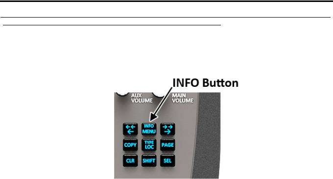
INFO button
The INFO button is used to access commonly used features and configuration options for the keypanels. These include the following:
Feature |
Description |
|
|
Panel ID |
Displays the port number and alpha of the keypanel. |
|
|
Level 2 |
Displays the Talk Level 2 key assignments on the keypanel. |
|
|
Listen |
Displays the listen key assignments on the keypanel. |
|
|
Callers |
Displays a list of current callers to the keypanel. |
|
|
Assign Types |
Displays the assignment types of all the configured keypanel keys. |
|
|
Matrices |
Displays the Matrix for each key assignment. |
|
|
Tone |
Opens the Tone Generator menu. For more information, see “Audio Options Menu, Tone Gen” on |
|
page 100. |
|
|
Setup Pages |
Displays the setup pages assigned to each row of keys. You cannot change setup pages from this menu. |
|
|
Reset Vols |
Opens the Key Volumes Reset menu. For more information, see “Audio Options Menu, Key Volumes” |
|
on page 96. |
|
|
Hidden Asgns |
Displays key assignments assigned to virtual keys (ie, assignments not currently visible). |
|
|
MAC Address |
Displays the MAC Address of the keypanel. |
|
|
Test Panel |
Enables the Test Panel feature. For more information, see “Service Menu, Test Panel” on page 131. |
|
|
Version |
Displays the firmware version of the DKP-3016. For more information, see “Display Menu, Version” on |
|
page 104. |
|
|
To access the Info Menu, do the following:
1.On the keypad, press the SHIFT button.
2.On the keypad, press the INFO MENU button.
The INFO menu appears in the panel display.
NOTE: To exit the INFO menu mode, press the CLR button.
Bosch Security Systems, Inc. |
Technical Manual |
F.01U.331.632 |
Rev. 01 |
30 Basic Operation |
DKP-3016 |
Breadcrumb Menu Navigation
Breadcrumb Navigation is a graphical aid to help users know where they are in the menu structure. The breadcrumb menu visually lays out a path of options selected up to the current menu position. It appears as a horizontal line above the menu options (shown in Figure 5).
FIGURE 5. Breadcrumb Navigation
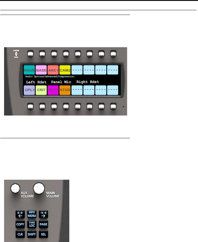
Menu Navigation and shaft encoders
While the keypanel is in menu mode, the AUX VOLUME shaft encoder is used to move the selection left and right. Or, in the case of a single menu item with up and down control, the shaft encoder is rotated to scroll through the available selections. This is particularly convenient when setting the display brightness or audio gain. Also, pressing the Aux Volume shaft encoder while in menu mode is the equivalent to SEL key operation. Conversely, pressing the MAIN VOLUME shaft encoder in menu mode is the equivalent to the CLR key operation.
FIGURE 6. DKP-3016 shaft encoders
Other navigation options:
•Press and hold the AUX VOLUME shaft encoder to exit the menu.
•Double-tap the AUX VOLUME shaft encoder to go backwards in the menu.
Bosch Security Systems, Inc. |
Technical Manual |
F.01U.331.632 |
Rev. 01 |
Loading...