

RTS EKP-32, KP-32, LCP-32 User Manual
9350-7656-000 Rev H, 8/2004
USER INSTRUCTIONS
KP-32 KEYPANEL
EKP-32 EXPANSION PANEL
LCP-32 LEVEL CONTROL PANEL

PROPRIETARY NOTICE
The RTS product information and design disclosed herein were originated by and are the property of Telex Communications, Inc. telex reserves all patent, proprietary design, manufacturing, reproduction, use and sales rights
thereto, and to any article disclosed therein, except to the extent rights are expressly granted to others.
COPYRIGHT NOTICE
Copyright © 2000 by Telex Communications, Inc. All rights reserved. Reproduction in whole or in part without
prior written permission from Telex is prohibited.
UNPACKING AND INSPECTION
Immediately upon receipt of the equipment, inspect the shipping container and the contents carefully for any discrepancies or damage. Should there be any, notify the freight company and the dealer at once.
WARRANTY INFORMATION
See the enclosed warranty card for further details.
CUSTOMER SUPPORT
Technical questions should be directed to:
Customer Service Department
RTS/ Telex
12000 Portland Avenue South
Burnsville, MN 55337 U.S.A.
Telephone: (800) 392-3497
Fax: (800) 323-0498
Factory Service: (800) 553-5992

RETURN SHIPPING INSTRUCTIONS
PROCEDURE FOR RETURNS
If a repair is necessary, contact the dealer where this unit was purchased.
If repair through the dealer is not possible, obtain a RETURN AUTHORIZATION from:
Customer Service Department
Telex Communications, Inc.
Telephone: (800) 392-3497
Fax: (800) 323-0498
Factory Service: (800) 553-5992
DO NOT RETURN ANY EQUIPMENT DIRECTLY TO THE FACTORY WITHOUT FIRST OBTAINING A
RETURN AUTHORIZATION.
Be prepared to provide the company name, address, phone number, a person to contact regarding the repair, the type
and quantity of equipment, a description of the problem and the serial number(s).
SHIPPING TO MANUFACTURER FOR REPAIR OR ADJUSTMENT
All shipments of RTS products should be made via United Parcel Service or the best available shipper, prepaid. The
equipment should be shipped in the original packing carton; if that is not available, use any suitable container that is
rigid and of adequate size. If a substitute container is used, the equipment should be wrapped in paper and surrounded
with at least four inches of excelsior or similar shock-absorbing material. All shipments must be sent to the following
address and must include the Return Authorization.
Factory Service Department
Telex Communications, Incorporated
8601 East Cornhusker Hwy
Lincoln, NE 68507 USA
Attn: Service
Upon completion of any repair the equipment will be returned via United Parcel Service or specified shipper collect.

End-User License Agreement for Telex® Software
IMPORTANT - Please read this document carefully before using this product.
THIS DOCUMENT STATES THE TERMS AND CONDITIONS UPON WHICH TELEX COMMUNICATIONS,
INC. (the “COMPANY”) OFFERS TO LICENSE THE INSTALLED SOFTWARE OR PROGRAM (the “SOFTWARE”) FOR USE WITH THE PRODUCT IN WHICH IT WAS INSTALLED. YOU ARE AGREEING TO
BECOME BOUND BY THE TERMS OF THIS AGREEMENT. IF YOU DO NOT AGREE TO THE TERMS OF
THIS AGREEMENT, DO NOT USE THIS PRODUCT. PROMPTLY RETURN THE PRODUCT TO THE
PLACE WHERE YOU OBTAINED IT FOR A FULL REFUND.
The installed software as supplied by the Company is licensed, not sold, to you for use only under the terms of this
license, and the Company reserves all rights not expressly granted to you. You own the product or other media on or
in which the Software is originally or subsequently recorded or fixed, but the Company retains ownership of all
copies of the Software itself.
1. License: This license allows you to use the Software for internal purposes only on a single product in which it
was installed.
2. Restrictions: (a) You may not market, distribute or transfer copies of the Software to others or electronically
transfer or duplicate the Software. YOU MAY NOT REVERSE ENGINEER, DECOMPILE, DISASSEMBLE,
MODIFY, ADAPT, TRANSLATE, RENT, LEASE OR LOAN THE SOFTWARE OR CREATE DERIVATIVE
WORKS BASED ON THE SOFTWARE OR ANY ACCOMPANYING WRITTEN MATERIALS. (b) The Software and the accompanying written materials are copyrighted. Unauthorized copying of the Software, including
portions thereof or the written materials, is expressly forbidden. (c) You understand that the Company may update
or revise the Software and in so doing incurs no obligation to furnish such updates to you.
3. Limited Warranty: The Company does not warrant that the operation of the Software will meet your requirements or operate free from error. The Company DISCLAIMS ALL OTHER WARRANTIES AND CONDITIONS
EITHER EXPRESS OR IMPLIED, INCLUDING THE WARRANTIES OF MERCHANTABILITY, FITNESS
FOR A PARTICULAR PURPOSE AND NON-INFRINGEMENT OF THIRD PARTY RIGHTS.
4. Limited Liability: The liability of the Company for any claims arising out of this License based upon the Software, regardless of the form of action, shall not exceed the greater of the license fee for the Software or $50.

i
TABLE OF CONTENTS
Introduction 1-1
Description . . . . . . . . . . . . . . . . . . . . . . . . . . . . . . . . . . . . . . . . . . . . . . . . . . . . . . . . . 1-1
Features . . . . . . . . . . . . . . . . . . . . . . . . . . . . . . . . . . . . . . . . . . . . . . . . . . . . . . . . . . 1-1
Options . . . . . . . . . . . . . . . . . . . . . . . . . . . . . . . . . . . . . . . . . . . . . . . . . . . . . . . . . . . 1-2
Connector Module . . . . . . . . . . . . . . . . . . . . . . . . . . . . . . . . . . . . . . . . . . . . . . . . . . 1-2
CSI-100 Coaxial System Interface Module . . . . . . . . . . . . . . . . . . . . . . . . . . . . . . . . . . . . . . 1-2
EKP-32 Expansion Keypanel. . . . . . . . . . . . . . . . . . . . . . . . . . . . . . . . . . . . . . . . . . . . . 1-3
LCP-32/16 Level Control Panels . . . . . . . . . . . . . . . . . . . . . . . . . . . . . . . . . . . . . . . . . . . 1-3
Installation 2-1
Option DIP Switch Settings . . . . . . . . . . . . . . . . . . . . . . . . . . . . . . . . . . . . . . . . . . . . . . . . . 2-1
Switch 1: Latch Enable/Disable . . . . . . . . . . . . . . . . . . . . . . . . . . . . . . . . . . . . . . . . . . . 2-1
Switch 2: Key Gain Enable / Disable . . . . . . . . . . . . . . . . . . . . . . . . . . . . . . . . . . . . . . . . . 2-1
Switch 3: Screen Saver Enable / Disable. . . . . . . . . . . . . . . . . . . . . . . . . . . . . . . . . . . . . . . 2-1
Switch 4: Call Flash Timeout . . . . . . . . . . . . . . . . . . . . . . . . . . . . . . . . . . . . . . . . . . . . . 2-2
Switch 5: Footswitch Enable / Disable*. . . . . . . . . . . . . . . . . . . . . . . . . . . . . . . . . . . . . . . . 2-2
Switch 6: Network Mode Selection . . . . . . . . . . . . . . . . . . . . . . . . . . . . . . . . . . . . . . . . . . 2-2
Switch 7: Test/Debug . . . . . . . . . . . . . . . . . . . . . . . . . . . . . . . . . . . . . . . . . . . . . . . . . 2-2
Switch 8: Test/Debug . . . . . . . . . . . . . . . . . . . . . . . . . . . . . . . . . . . . . . . . . . . . . . . . . 2-2
Address Switch Setting . . . . . . . . . . . . . . . . . . . . . . . . . . . . . . . . . . . . . . . . . . . . . . . . . . . 2-2
General Information . . . . . . . . . . . . . . . . . . . . . . . . . . . . . . . . . . . . . . . . . . . . . . . . . . . 2-2
Address Setting for Zeus . . . . . . . . . . . . . . . . . . . . . . . . . . . . . . . . . . . . . . . . . . . . . . . . 2-3
Address Setting for ADAM CS. . . . . . . . . . . . . . . . . . . . . . . . . . . . . . . . . . . . . . . . . . . . . . 2-3
ADAM CS with RJ12 or DB-9 back panel: . . . . . . . . . . . . . . . . . . . . . . . . . . . . . . . . . . . . . . 2-3
ADAM CS with 50-pin Telco back panel: . . . . . . . . . . . . . . . . . . . . . . . . . . . . . . . . . . . . . . . 2-4
Address Setting for ADAM. . . . . . . . . . . . . . . . . . . . . . . . . . . . . . . . . . . . . . . . . . . . . . . . 2-5
Connections . . . . . . . . . . . . . . . . . . . . . . . . . . . . . . . . . . . . . . . . . . . . . . . . . . . . . . . . 2-5
EXP. AND LCP Connectors . . . . . . . . . . . . . . . . . . . . . . . . . . . . . . . . . . . . . . . . . . . . . . . 2-5
Frame Connector . . . . . . . . . . . . . . . . . . . . . . . . . . . . . . . . . . . . . . . . . . . . . . . . . . . . 2-5
Power Supply Connector . . . . . . . . . . . . . . . . . . . . . . . . . . . . . . . . . . . . . . . . . . . . . . . . . . 2-6
Headset Connector . . . . . . . . . . . . . . . . . . . . . . . . . . . . . . . . . . . . . . . . . . . . . . . . . . . . . 2-6
Headset Microphone Gain Adjustment . . . . . . . . . . . . . . . . . . . . . . . . . . . . . . . . . . . . . . . . . 2-6
Panel Microphone Connector. . . . . . . . . . . . . . . . . . . . . . . . . . . . . . . . . . . . . . . . . . . . . . . . 2-6
Panel Microphone Gain Adjustment . . . . . . . . . . . . . . . . . . . . . . . . . . . . . . . . . . . . . . . . . . . 2-7
Basic Operation 3-1
Screen Saver Operation . . . . . . . . . . . . . . . . . . . . . . . . . . . . . . . . . . . . . . . . . . . . . . . . . . 3-1
Selecting Headset or Speaker . . . . . . . . . . . . . . . . . . . . . . . . . . . . . . . . . . . . . . . . . . . . . . . 3-1
Listen Volume Adjustments . . . . . . . . . . . . . . . . . . . . . . . . . . . . . . . . . . . . . . . . . . . . . . . . . 3-1
Intercom Keys and Displays . . . . . . . . . . . . . . . . . . . . . . . . . . . . . . . . . . . . . . . . . . . . . . . . 3-2
Alphanumeric Display Indications for Intercom Keys . . . . . . . . . . . . . . . . . . . . . . . . . . . . . . . . . . 3-2
LED Indications for Intercom Keys. . . . . . . . . . . . . . . . . . . . . . . . . . . . . . . . . . . . . . . . . . . . 3-2
Talk LED Indications . . . . . . . . . . . . . . . . . . . . . . . . . . . . . . . . . . . . . . . . . . . . . . . . . 3-2
Continuous Green* . . . . . . . . . . . . . . . . . . . . . . . . . . . . . . . . . . . . . . . . . . . . . . . . . . . . . . . . 3-2
Continuous Red Talk LED & Flashing Display Alpha ("In-use")* . . . . . . . . . . . . . . . . . . . . . . . . . . . . . . . . . 3-2
Flashing Red Talk LED & Flashing Display Alternating Pattern of Alpha & (-**-) ("Busy") . . . . . . . . . . . . . . . . . . . . 3-2
Flashing Green Talk LED & Display Alpha (on time equal to off time)* . . . . . . . . . . . . . . . . . . . . . . . . . . . . . . 3-3
Winking Green Talk LED (on time less than off time)* . . . . . . . . . . . . . . . . . . . . . . . . . . . . . . . . . . . . . . 3-3
Listen LED Indication. . . . . . . . . . . . . . . . . . . . . . . . . . . . . . . . . . . . . . . . . . . . . . . . . 3-3
Intercom Key Operation . . . . . . . . . . . . . . . . . . . . . . . . . . . . . . . . . . . . . . . . . . . . . . . . . 3-3
Basic Intercom Key Operation . . . . . . . . . . . . . . . . . . . . . . . . . . . . . . . . . . . . . . . . . . . . 3-3
Operation of Intercom Keys with Auto Functions. . . . . . . . . . . . . . . . . . . . . . . . . . . . . . . . . . . 3-3
Talk + auto follow . . . . . . . . . . . . . . . . . . . . . . . . . . . . . . . . . . . . . . . . . . . . . . . . . . . . . . . . . 3-3
Talk + auto listen . . . . . . . . . . . . . . . . . . . . . . . . . . . . . . . . . . . . . . . . . . . . . . . . . . . . . . . . . 3-3
Talk + auto mute. . . . . . . . . . . . . . . . . . . . . . . . . . . . . . . . . . . . . . . . . . . . . . . . . . . . . . . . . . 3-3
Talk + auto reciprocal . . . . . . . . . . . . . . . . . . . . . . . . . . . . . . . . . . . . . . . . . . . . . . . . . . . . . . . 3-4

ii
Talk + auto table . . . . . . . . . . . . . . . . . . . . . . . . . . . . . . . . . . . . . . . . . . . . . . . . . . . . . . . . . 3-4
All Call Key . . . . . . . . . . . . . . . . . . . . . . . . . . . . . . . . . . . . . . . . . . . . . . . . . . . . . . . . . . . . 3-4
Talk + DIM . . . . . . . . . . . . . . . . . . . . . . . . . . . . . . . . . . . . . . . . . . . . . . . . . . . . . . . . . . . . 3-4
Operation of Intercom Keys with Options . . . . . . . . . . . . . . . . . . . . . . . . . . . . . . . . . . . . . . .3-4
Group Option Keys . . . . . . . . . . . . . . . . . . . . . . . . . . . . . . . . . . . . . . . . . . . . . . . . . . . . . . . . 3-4
Solo Key . . . . . . . . . . . . . . . . . . . . . . . . . . . . . . . . . . . . . . . . . . . . . . . . . . . . . . . . . . . . . 3-4
Operation of Intercom Talk Keys with the Speaker DIM Setting . . . . . . . . . . . . . . . . . . . . . . . . . . . .3-4
Operation of Intercom Keys assigned to TIF Ports. . . . . . . . . . . . . . . . . . . . . . . . . . . . . . . . . . .3-4
Muting the Microphone . . . . . . . . . . . . . . . . . . . . . . . . . . . . . . . . . . . . . . . . . . . . . . . . . . . .3-5
Call Waiting Operation . . . . . . . . . . . . . . . . . . . . . . . . . . . . . . . . . . . . . . . . . . . . . . . . . . . . 3-5
Telephone Operation 4-1
Receiving A Phone Call . . . . . . . . . . . . . . . . . . . . . . . . . . . . . . . . . . . . . . . . . . . . . . . . . . .4-1
DIALING AND HANGING UP USING KP9X KEYPAD SEQUENCES . . . . . . . . . . . . . . . . . . . . . . . . . . . .4-1
KP9X Keypad Hang-up Sequence . . . . . . . . . . . . . . . . . . . . . . . . . . . . . . . . . . . . . . . . . . . .4-1
KP9X Manual dial sequence . . . . . . . . . . . . . . . . . . . . . . . . . . . . . . . . . . . . . . . . . . . . . . .4-1
KP9X Redial Sequence . . . . . . . . . . . . . . . . . . . . . . . . . . . . . . . . . . . . . . . . . . . . . . . . . .4-2
KP9X Autodial Sequences . . . . . . . . . . . . . . . . . . . . . . . . . . . . . . . . . . . . . . . . . . . . . . . . 4-2
Storing an Autodial Number in the TIF-951 . . . . . . . . . . . . . . . . . . . . . . . . . . . . . . . . . . . . . . . . 4-2
Dialing an Autodial Number Stored in the TIF-951 . . . . . . . . . . . . . . . . . . . . . . . . . . . . . . . . . . . . 4-3
DIALING AND HANGING UP USING THE KP-32 DIALING MENU . . . . . . . . . . . . . . . . . . . . . . . . . . . . . 4-3
Manual Dialing . . . . . . . . . . . . . . . . . . . . . . . . . . . . . . . . . . . . . . . . . . . . . . . . . . . . . .4-3
Redial . . . . . . . . . . . . . . . . . . . . . . . . . . . . . . . . . . . . . . . . . . . . . . . . . . . . . . . . . . .4-3
Autodial . . . . . . . . . . . . . . . . . . . . . . . . . . . . . . . . . . . . . . . . . . . . . . . . . . . . . . . . . . 4-4
KP9X Series Keypad Programming 5-1
KEYPAD PROGRAMMING, DISPLAY REQUESTS . . . . . . . . . . . . . . . . . . . . . . . . . . . . . . . . . . . . . 5-1
Display Requests Using Keypad Sequences . . . . . . . . . . . . . . . . . . . . . . . . . . . . . . . . . . . . . . . 5-1
Display Panel ID. . . . . . . . . . . . . . . . . . . . . . . . . . . . . . . . . . . . . . . . . . . . . . . . . . . . . .5-1
Display Level 2 Talk Key Assignments . . . . . . . . . . . . . . . . . . . . . . . . . . . . . . . . . . . . . . . . . . 5-1
Display Listen Key Assignments . . . . . . . . . . . . . . . . . . . . . . . . . . . . . . . . . . . . . . . . . . . . . 5-1
Display Setup Page Assignments . . . . . . . . . . . . . . . . . . . . . . . . . . . . . . . . . . . . . . . . . . . . . 5-2
Test Keys and Displays . . . . . . . . . . . . . . . . . . . . . . . . . . . . . . . . . . . . . . . . . . . . . . . . . . 5-2
Tone Generator Activation (FUNC-DISPLAY-7) . . . . . . . . . . . . . . . . . . . . . . . . . . . . . . . . . . . . . .5-3
Display Requests Using Scrolling . . . . . . . . . . . . . . . . . . . . . . . . . . . . . . . . . . . . . . . . . . . . .5-3
KEYPAD PROGRAMMING, ASSIGNING SETUP PAGES. . . . . . . . . . . . . . . . . . . . . . . . . . . . . . . . . . 5-3
KEYPAD PROGRAMMING, ASSIGNING INTERCOM KEYS . . . . . . . . . . . . . . . . . . . . . . . . . . . . . . . . 5-4
General . . . . . . . . . . . . . . . . . . . . . . . . . . . . . . . . . . . . . . . . . . . . . . . . . . . . . . . . . .5-4
Assigning Keys Using Keypad Numeric Entry . . . . . . . . . . . . . . . . . . . . . . . . . . . . . . . . . . . . . .5-4
General Procedure. . . . . . . . . . . . . . . . . . . . . . . . . . . . . . . . . . . . . . . . . . . . . . . . . . . 5-4
Programming Key Assignments Using Copy . . . . . . . . . . . . . . . . . . . . . . . . . . . . . . . . . . . . . . .5-5
Copying a Call from the Call waiting Window to a Key . . . . . . . . . . . . . . . . . . . . . . . . . . . . . . . . . . 5-5
Copying One Key Assignment to Another Key . . . . . . . . . . . . . . . . . . . . . . . . . . . . . . . . . . . . . . 5-5
Programming Key Assignments Using Alpha Scrolling . . . . . . . . . . . . . . . . . . . . . . . . . . . . . . . . . .5-6
Clearing a Key Assignment . . . . . . . . . . . . . . . . . . . . . . . . . . . . . . . . . . . . . . . . . . . . . . . . 5-7
Method 1: Clearing the Call waiting Window and Copying it to a Key . . . . . . . . . . . . . . . . . . . . . . . . . 5-7
Method 2: Copying a Blank Key Assignment to the Key that You want to Clear . . . . . . . . . . . . . . . . . . . .5-7
KP-32 Menu System 6-1
MENU SYSTEM, MENU ACCESS. . . . . . . . . . . . . . . . . . . . . . . . . . . . . . . . . . . . . . . . . . . . . .6-1
MENU SYSTEM, DISPLAY MENU . . . . . . . . . . . . . . . . . . . . . . . . . . . . . . . . . . . . . . . . . . . . . .6-1
Display Menu, Asgn Type . . . . . . . . . . . . . . . . . . . . . . . . . . . . . . . . . . . . . . . . . . . . . . . . . 6-1
Display Menu, Chans On . . . . . . . . . . . . . . . . . . . . . . . . . . . . . . . . . . . . . . . . . . . . . . . . . 6-2
Display Menu, Key Groups . . . . . . . . . . . . . . . . . . . . . . . . . . . . . . . . . . . . . . . . . . . . . . . .6-2
Display Menu, Key List . . . . . . . . . . . . . . . . . . . . . . . . . . . . . . . . . . . . . . . . . . . . . . . . . .6-2
Display Menu, Level 2. . . . . . . . . . . . . . . . . . . . . . . . . . . . . . . . . . . . . . . . . . . . . . . . . . .6-2
Display Menu, Listen . . . . . . . . . . . . . . . . . . . . . . . . . . . . . . . . . . . . . . . . . . . . . . . . . . .6-2
Display Menu, Matrix . . . . . . . . . . . . . . . . . . . . . . . . . . . . . . . . . . . . . . . . . . . . . . . . . . . 6-2
Display Menu, Panel ID . . . . . . . . . . . . . . . . . . . . . . . . . . . . . . . . . . . . . . . . . . . . . . . . . .6-2
Display Menu, Version . . . . . . . . . . . . . . . . . . . . . . . . . . . . . . . . . . . . . . . . . . . . . . . . . .6-2

iii
MENU SYSTEM, KEY ASSIGN MENU. . . . . . . . . . . . . . . . . . . . . . . . . . . . . . . . . . . . . . . . . . . 6-3
General Procedure to use the Key Assign Menu . . . . . . . . . . . . . . . . . . . . . . . . . . . . . . . . . . . . 6-3
Key Assign Menu, Matrix . . . . . . . . . . . . . . . . . . . . . . . . . . . . . . . . . . . . . . . . . . . . . . . . 6-4
Key Assign Menu, Pt-to-Pt. . . . . . . . . . . . . . . . . . . . . . . . . . . . . . . . . . . . . . . . . . . . . . . . 6-4
Key Assign Menu, Party Line . . . . . . . . . . . . . . . . . . . . . . . . . . . . . . . . . . . . . . . . . . . . . . 6-5
Key Assign Menu, IFB . . . . . . . . . . . . . . . . . . . . . . . . . . . . . . . . . . . . . . . . . . . . . . . . . . 6-5
Key Assign Menu, Spcl List . . . . . . . . . . . . . . . . . . . . . . . . . . . . . . . . . . . . . . . . . . . . . . . 6-5
Key Assign Menu, Sys Relay . . . . . . . . . . . . . . . . . . . . . . . . . . . . . . . . . . . . . . . . . . . . . . 6-5
Key Assign Menu, Camera ISO . . . . . . . . . . . . . . . . . . . . . . . . . . . . . . . . . . . . . . . . . . . . . 6-5
Key Assign Menu, UPL Resrc . . . . . . . . . . . . . . . . . . . . . . . . . . . . . . . . . . . . . . . . . . . . . . 6-5
Key Assign Menu, Auto Func . . . . . . . . . . . . . . . . . . . . . . . . . . . . . . . . . . . . . . . . . . . . . . 6-5
Key Assign Menu, Key Gain . . . . . . . . . . . . . . . . . . . . . . . . . . . . . . . . . . . . . . . . . . . . . . . 6-6
Key Assign Menu, Reset Vols . . . . . . . . . . . . . . . . . . . . . . . . . . . . . . . . . . . . . . . . . . . . . . 6-6
Key Assign Menu, Setup Page . . . . . . . . . . . . . . . . . . . . . . . . . . . . . . . . . . . . . . . . . . . . . 6-7
KEY OPTION MENU . . . . . . . . . . . . . . . . . . . . . . . . . . . . . . . . . . . . . . . . . . . . . . . . . . . . 6-7
Key Option Menu, Auto Dial . . . . . . . . . . . . . . . . . . . . . . . . . . . . . . . . . . . . . . . . . . . . . . . 6-7
Key Option Menu, Chime . . . . . . . . . . . . . . . . . . . . . . . . . . . . . . . . . . . . . . . . . . . . . . . . 6-7
Removing the chime option from a key. . . . . . . . . . . . . . . . . . . . . . . . . . . . . . . . . . . . . . . . 6-8
Key Option Menu, Key Groups . . . . . . . . . . . . . . . . . . . . . . . . . . . . . . . . . . . . . . . . . . . . . 6-8
Clearing a key group. . . . . . . . . . . . . . . . . . . . . . . . . . . . . . . . . . . . . . . . . . . . . . . . . . . 6-8
Key Option Menu, Solo . . . . . . . . . . . . . . . . . . . . . . . . . . . . . . . . . . . . . . . . . . . . . . . . . 6-9
Removing the solo key option . . . . . . . . . . . . . . . . . . . . . . . . . . . . . . . . . . . . . . . . . . . . 6-9
SERVICE MENU . . . . . . . . . . . . . . . . . . . . . . . . . . . . . . . . . . . . . . . . . . . . . . . . . . . . . . 6-9
Service Menu, Aux Inputs . . . . . . . . . . . . . . . . . . . . . . . . . . . . . . . . . . . . . . . . . . . . . . . . 6-9
Service Menu, Dim . . . . . . . . . . . . . . . . . . . . . . . . . . . . . . . . . . . . . . . . . . . . . . . . . . . 6-9
Service Menu, Disply Dim . . . . . . . . . . . . . . . . . . . . . . . . . . . . . . . . . . . . . . . . . . . . . . . . 6-10
Service Menu, DSP Func . . . . . . . . . . . . . . . . . . . . . . . . . . . . . . . . . . . . . . . . . . . . . . . . 6-10
Filtering. . . . . . . . . . . . . . . . . . . . . . . . . . . . . . . . . . . . . . . . . . . . . . . . . . . . . . . . 6-11
Gating . . . . . . . . . . . . . . . . . . . . . . . . . . . . . . . . . . . . . . . . . . . . . . . . . . . . . . . . 6-11
Metering . . . . . . . . . . . . . . . . . . . . . . . . . . . . . . . . . . . . . . . . . . . . . . . . . . . . . . . 6-11
Mixing . . . . . . . . . . . . . . . . . . . . . . . . . . . . . . . . . . . . . . . . . . . . . . . . . . . . . . . . 6-12
Service Menu, Hdst Sel . . . . . . . . . . . . . . . . . . . . . . . . . . . . . . . . . . . . . . . . . . . . . . . . . 6-12
Service Menu, LCP-32 . . . . . . . . . . . . . . . . . . . . . . . . . . . . . . . . . . . . . . . . . . . . . . . . . 6-13
Service Menu, Local GPIO . . . . . . . . . . . . . . . . . . . . . . . . . . . . . . . . . . . . . . . . . . . . . . . 6-13
Assigning an Input to Activate a Key . . . . . . . . . . . . . . . . . . . . . . . . . . . . . . . . . . . . . . . . . 6-13
Assigning an Input to Activate a Key Group . . . . . . . . . . . . . . . . . . . . . . . . . . . . . . . . . . . . . 6-14
Removing an Input Assignment . . . . . . . . . . . . . . . . . . . . . . . . . . . . . . . . . . . . . . . . . . . 6-14
Adding or Removing a GPI Output Key Assignment . . . . . . . . . . . . . . . . . . . . . . . . . . . . . . . . . 6-14
Service Menu, Matrix Out . . . . . . . . . . . . . . . . . . . . . . . . . . . . . . . . . . . . . . . . . . . . . . . . 6-15
Service Menu, Mic Select . . . . . . . . . . . . . . . . . . . . . . . . . . . . . . . . . . . . . . . . . . . . . . . . 6-15
Service Menu, Min Volume . . . . . . . . . . . . . . . . . . . . . . . . . . . . . . . . . . . . . . . . . . . . . . . 6-15
Service Menu, Mod Assign . . . . . . . . . . . . . . . . . . . . . . . . . . . . . . . . . . . . . . . . . . . . . . . 6-16
Service Menu, Output Level . . . . . . . . . . . . . . . . . . . . . . . . . . . . . . . . . . . . . . . . . . . . . . . 6-16
Service Menu, Preamp Out (GPI Option Only) . . . . . . . . . . . . . . . . . . . . . . . . . . . . . . . . . . . . . 6-17
Service Menu, Reset Cfg . . . . . . . . . . . . . . . . . . . . . . . . . . . . . . . . . . . . . . . . . . . . . . . . 6-17
Service Menu, Save Cfg. . . . . . . . . . . . . . . . . . . . . . . . . . . . . . . . . . . . . . . . . . . . . . . . . 6-17
Service Menu, Sidetone . . . . . . . . . . . . . . . . . . . . . . . . . . . . . . . . . . . . . . . . . . . . . . . . . 6-17
Service Menu, Test Panel . . . . . . . . . . . . . . . . . . . . . . . . . . . . . . . . . . . . . . . . . . . . . . . . 6-17
Service Menu, Tone Gen . . . . . . . . . . . . . . . . . . . . . . . . . . . . . . . . . . . . . . . . . . . . . . . . 6-18
Specifications 7-1
Microphone Preamplifier . . . . . . . . . . . . . . . . . . . . . . . . . . . . . . . . . . . . . . . . . . . . . . . . . . 7-1
Tone Generator . . . . . . . . . . . . . . . . . . . . . . . . . . . . . . . . . . . . . . . . . . . . . . . . . . . . . . . 7-1
Headphone Amplifier . . . . . . . . . . . . . . . . . . . . . . . . . . . . . . . . . . . . . . . . . . . . . . . . . . . . 7-1
Speaker Amplifier and Speaker. . . . . . . . . . . . . . . . . . . . . . . . . . . . . . . . . . . . . . . . . . . . . . . 7-1
Intercom Input/Output. . . . . . . . . . . . . . . . . . . . . . . . . . . . . . . . . . . . . . . . . . . . . . . . . . . . 7-2
External Line Input: (Program Input) . . . . . . . . . . . . . . . . . . . . . . . . . . . . . . . . . . . . . . . . . . . . 7-2
General . . . . . . . . . . . . . . . . . . . . . . . . . . . . . . . . . . . . . . . . . . . . . . . . . . . . . . . . . . . 7-2
AC Supply: . . . . . . . . . . . . . . . . . . . . . . . . . . . . . . . . . . . . . . . . . . . . . . . . . . . . . . 7-2
Environmental: . . . . . . . . . . . . . . . . . . . . . . . . . . . . . . . . . . . . . . . . . . . . . . . . . . . . 7-2

iv
Approvals: . . . . . . . . . . . . . . . . . . . . . . . . . . . . . . . . . . . . . . . . . . . . . . . . . . . . . . .7-2
Connectors (Other connector options available) . . . . . . . . . . . . . . . . . . . . . . . . . . . . . . . . . . . . . . . 7-2
Panel Microphone Connector . . . . . . . . . . . . . . . . . . . . . . . . . . . . . . . . . . . . . . . . . . . . . . .7-2
Headset Connector . . . . . . . . . . . . . . . . . . . . . . . . . . . . . . . . . . . . . . . . . . . . . . . . . . . . 7-2
Power Input Connector . . . . . . . . . . . . . . . . . . . . . . . . . . . . . . . . . . . . . . . . . . . . . . . . . .7-3
Intercom Connectors: Parallel-wired DE9S and RJ12 Connectors . . . . . . . . . . . . . . . . . . . . . . . . . . . . 7-3
Expansion Connector . . . . . . . . . . . . . . . . . . . . . . . . . . . . . . . . . . . . . . . . . . . . . . . . . . .7-3
LCP Connector . . . . . . . . . . . . . . . . . . . . . . . . . . . . . . . . . . . . . . . . . . . . . . . . . . . . . . 7-3
GPI Module Conntectors (Optional) . . . . . . . . . . . . . . . . . . . . . . . . . . . . . . . . . . . . . . . . . . . . . 7-4
Aux 1 In (Auxiliary program input 1). . . . . . . . . . . . . . . . . . . . . . . . . . . . . . . . . . . . . . . . . . . .7-4
Aux 2 In (Auxiliary program input 2). . . . . . . . . . . . . . . . . . . . . . . . . . . . . . . . . . . . . . . . . . . .7-4
Relay 1 & 2 Out . . . . . . . . . . . . . . . . . . . . . . . . . . . . . . . . . . . . . . . . . . . . . . . . . . . . . .7-4
Relay 3 & 4 Out . . . . . . . . . . . . . . . . . . . . . . . . . . . . . . . . . . . . . . . . . . . . . . . . . . . . . .7-4
Opto 1-4 In (Opto-isolated control inputs). . . . . . . . . . . . . . . . . . . . . . . . . . . . . . . . . . . . . . . . . 7-5
OC 1 & 2 Out (J2) . . . . . . . . . . . . . . . . . . . . . . . . . . . . . . . . . . . . . . . . . . . . . . . . . . . . .7-5
Headset (External headset connector) . . . . . . . . . . . . . . . . . . . . . . . . . . . . . . . . . . . . . . . . . . 7-5
Foot Switch/Speaker . . . . . . . . . . . . . . . . . . . . . . . . . . . . . . . . . . . . . . . . . . . . . . . . . . .7-6
MIC In (J7) Unbalanced Panel Microphone Input . . . . . . . . . . . . . . . . . . . . . . . . . . . . . . . . . . . . .7-6
MIC Out (J8) Balanced Microphone Output . . . . . . . . . . . . . . . . . . . . . . . . . . . . . . . . . . . . . . . .7-6
KP9X Keypad Sequence Quick Reference 8-1
KP9X DISPLAY SEQUENCES . . . . . . . . . . . . . . . . . . . . . . . . . . . . . . . . . . . . . . . . . . . . . . . .8-1
KP9X SETUP PAGE ASSIGNMENT . . . . . . . . . . . . . . . . . . . . . . . . . . . . . . . . . . . . . . . . . . . . .8-1
KEY ASSIGNMENTS USING KEYPAD NUMERIC ENTRY . . . . . . . . . . . . . . . . . . . . . . . . . . . . . . . . .8-2
KP9X PHONE OPERATION . . . . . . . . . . . . . . . . . . . . . . . . . . . . . . . . . . . . . . . . . . . . . . . . . 8-2
KP9X Hang-up Sequence. . . . . . . . . . . . . . . . . . . . . . . . . . . . . . . . . . . . . . . . . . . . . . . . .8-2
KP9X Dial Sequence . . . . . . . . . . . . . . . . . . . . . . . . . . . . . . . . . . . . . . . . . . . . . . . . . . .8-3
KP9X Redial Sequence . . . . . . . . . . . . . . . . . . . . . . . . . . . . . . . . . . . . . . . . . . . . . . . . . .8-3
KP9X Autodial Sequences . . . . . . . . . . . . . . . . . . . . . . . . . . . . . . . . . . . . . . . . . . . . . . . . 8-3
Storing an Autodial Number in the TIF-951 . . . . . . . . . . . . . . . . . . . . . . . . . . . . . . . . . . . . . . 8-3
Dialing an Autodial Number Stored in the TIF-951. . . . . . . . . . . . . . . . . . . . . . . . . . . . . . . . . . .8-3
KP-32 Menu System Quick Reference 9-1
MENU ACCESS . . . . . . . . . . . . . . . . . . . . . . . . . . . . . . . . . . . . . . . . . . . . . . . . . . . . . . .9-1
MENU LIST. . . . . . . . . . . . . . . . . . . . . . . . . . . . . . . . . . . . . . . . . . . . . . . . . . . . . . . . . . 9-1
Mode 2 Operation 10-1
Section 2 . . . . . . . . . . . . . . . . . . . . . . . . . . . . . . . . . . . . . . . . . . . . . . . . . . . . . . . . . . 10-1
Switch 4: Call Flash Timeout* . . . . . . . . . . . . . . . . . . . . . . . . . . . . . . . . . . . . . . . . . . . . 10-1
Switch 5: Footswitch Enable / Disable* . . . . . . . . . . . . . . . . . . . . . . . . . . . . . . . . . . . . . . . 10-1
Section 3 . . . . . . . . . . . . . . . . . . . . . . . . . . . . . . . . . . . . . . . . . . . . . . . . . . . . . . . . . . 10-1
LED Indications for Intercom Keys . . . . . . . . . . . . . . . . . . . . . . . . . . . . . . . . . . . . . . . . . . . 10-1
Talk LED Indications . . . . . . . . . . . . . . . . . . . . . . . . . . . . . . . . . . . . . . . . . . . . . . . . . 10-1
Continuous Red* . . . . . . . . . . . . . . . . . . . . . . . . . . . . . . . . . . . . . . . . . . . . . . . . . . . . . . . . . 10-1
Flashing Display Alpha ("In-use")* . . . . . . . . . . . . . . . . . . . . . . . . . . . . . . . . . . . . . . . . . . . . . . . .10-1
Solid Red Talk LED & Flashing Display Alternating Pattern of Alpha & (-**-) ("Busy"). . . . . . . . . . . . . . . . . . . . . . 10-2
Flashing Display Alpha (on time equal to off time)* . . . . . . . . . . . . . . . . . . . . . . . . . . . . . . . . . . . . . . . 10-2
Amber Talk LED . . . . . . . . . . . . . . . . . . . . . . . . . . . . . . . . . . . . . . . . . . . . . . . . . . . . . . . . . 10-2
Glossary 11-1
Appendix 12-1
1-1
S ECTION
1
C
HAPTER
1
I
NTRODUCTION
Description
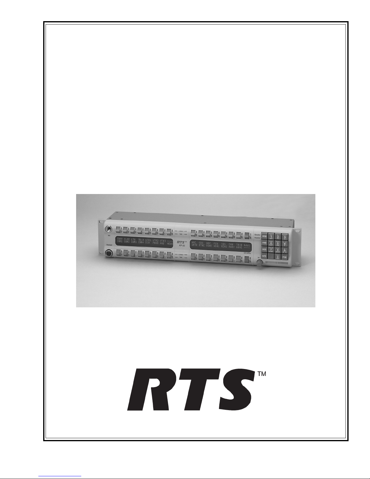
Figure 1.1
KP-32 keypanel front view..
The RTS™ Model KP-32 Keypanel fits in a standard 19" rack and is two rack spaces high. It has
32 lever keys: 30 keys are for intercom talk/listen assignment; one key is for call waiting
response; and one key is for headset/microphone/program selection and volume setup. The KP-32
combines all of the programmable features of the KP9X Series Keypanels and the KP-12
Keypanel. It adds significant new features such as digital signal processing and binaural headset
operation with left/right assignment of audio signals. The KP-32 also introduces large, superbright, long-life fluorescent displays with adjustable brightness control, making it suitable for all
types of ambient lighting from direct sunlight to darkness.
Features
• Super-bright, fluorescent displays: Provide much better visibility and useable life than LCD
displays. A display saver mode with programmable scrolling message extends display life and
conserves power during periods of inactivity.
• 32 lever keys, with 30 keys available for full talk/listen configuration: Doubles the number of
channels over the KP9X series keypanels. Keys support both latching (hands-free) and
momentary (push-to-talk) operation.
• Enhanced programming keypad: Provides the complete KP9X keypad sequences, plus new
keypad sequences, plus an extensive scrollable menu system. Menus include helpful prompts
to walk the user through setup.
1-2 KP-32 User Manual
• Only 90 mm deep behind the front panel (approximately 130 mm with connectors): Perfect for
consoles, OB vans, etc.
• Digital Signal Processing (DSP): Improves microphone voice activation and limiting. Adds
new mixing, metering, and filtering capabilities.
• Binaural (5-pin) Headset Connector: Works with the DSP mixing feature. Lets you
independently assign intercom, microphone, and program audio to left or right headphone.
Note: monaural (4-pin) connector available as an option. For monaural operation, the mixer
lets you select which items are monitored in the headphones.
• Easy upgrades: Firmware updates can be received via the internet, for example, and then
downloaded to the KP-32 via the intercom connection. Ready for future communication
enhancements, including coax, fiber, and ISDN. (For further information, search for keyword
"firmware" in ADAMedit help.)
Options
Connector Module
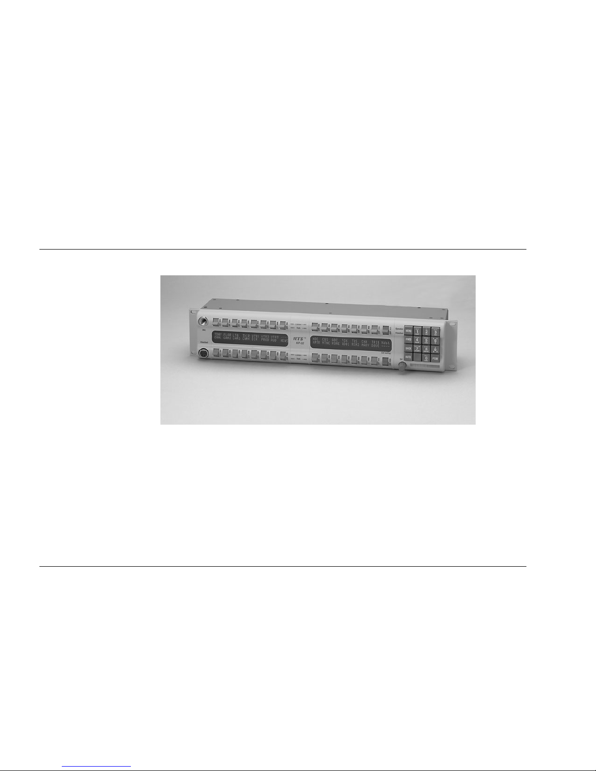
Figure 1.2
KP-32 connector option board.
Provides connectors for two line-level audio inputs (program 1 and 2), an unswitched, balanced
microphone preamplifier output, an external headset, an external speaker output, and a foot
switch input (for remote switch activation of all "armed" talk keys, or just one key). Also includes
a General Purpose Input / Output (GPIO), with four opto-isolated inputs, two open-collector
outputs, and two SPDT relay outputs. Inputs can activate single keys and groups of keys. Outputs
can activate external devices from keypanel keys or from GPI inputs. Available factory installed
or as an add-on kit.
CSI-100 Coaxial System Interface Module
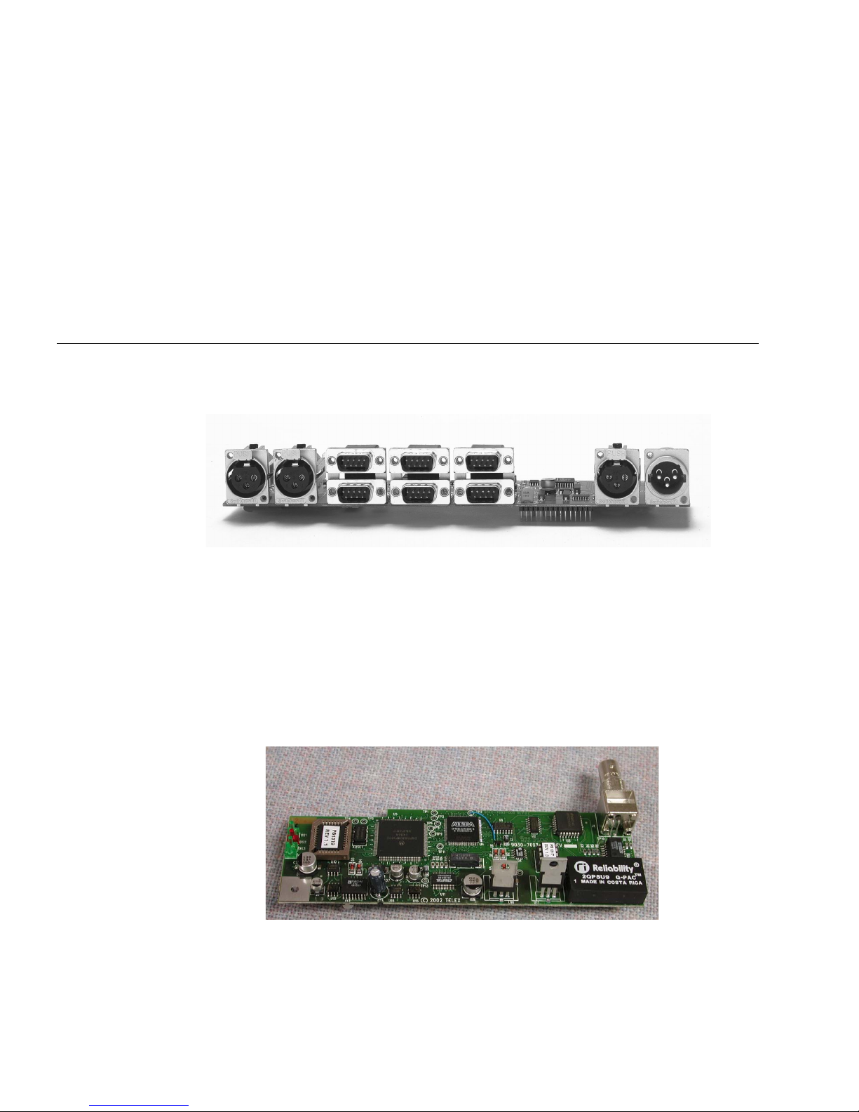
Figure 1.3
KP-32 CSI-100 coaxial system interface board.
Provides the ability to link the unit to the matrix using a single 75 ohm coaxial cable. The
interface converts all audio and data streams to a single transmission path. Perfect for systems
where there are existing, but unused 75 ohm video cable. Requires a CSI-200 interface unit at the
intercom matrix end.
1-3
EKP-32 Expansion Keypanel
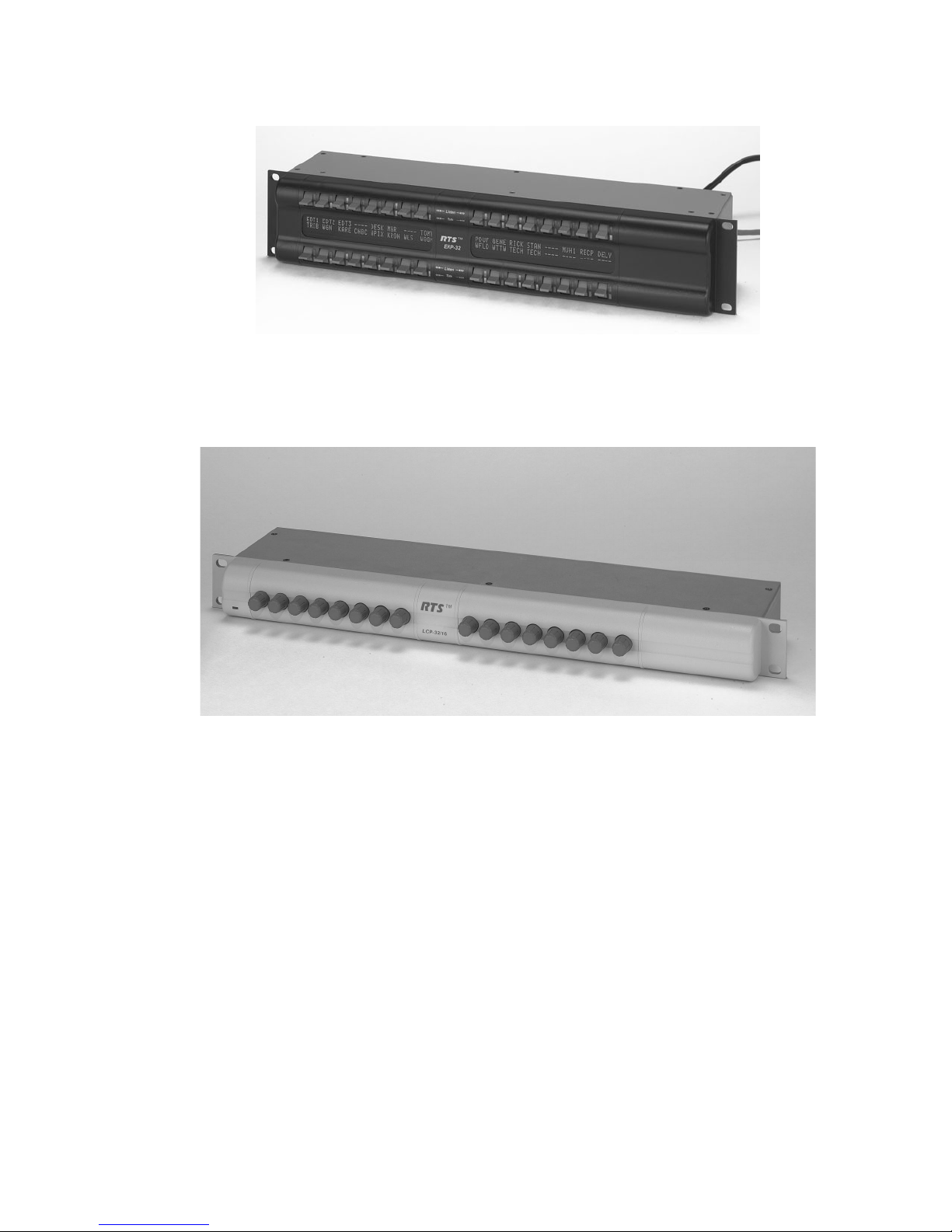
Figure 1.4
EKP-32 expansion keypanel front view.
Provides and additional 32 intercom keys for a total of up to 64 keys (62 intercom keys total).
LCP-32/16 Level Control Panels
Figure 1.5
LCP-32/16 level control panel front view.
Provides easy adjustment of point-to-point and party line listen levels for individual intercom
keys. One LCP-32/16 adjusts one row of keys.

1-4 KP-32 User Manual
This Page Left Blank Intentionally

2-1
S ECTION
2
C
HAPTER
2
I
NSTALLATION
Option DIP Switch Settings
Switch 1: Latch Enable/Disable
Default setting = Open: Enable.
Description: An intercom key can always be turned on for momentary conversation by pressing
and holding the key during the conversation. There is also an electronic latching feature that lets
you tap intercom keys to turn them on or off. This permits convenient hands-free conversation.
However it can also result in a talk circuit being left on unintentionally. For example: A key that
talks to a public address system could be accidentally left on. Or an IFB key (a type of key
assignment that is often used by a director or producer to give instructions to a listener, such as a
news anchor during a television broadcast) could accidentally be left on, causing confusion for
the IFB listener. To prevent such accidents, the latching feature can be turned off.
Note
DIP switch 1 disables latching for the entire keypanel. If you just need to disable latching for
selected keys, leave DIP switch 1 in the "Open" position. Then, disable latching for the desired
keys using the "D" check boxes in the Keypanels / Ports setup screen of ADAMedit.
Switch 2: Key Gain Enable / Disable
Default setting = Open: Enable.
Description: Enables or disables the Key Gain item in the Key Assign menu.
Switch 3: Screen Saver Enable / Disable
Default setting = Open: Enable.
With Screen Saver enabled, the KP-32 will shut off the display and enter a low-power state after a
few minutes of inactivity. The display reactivates instantaneously on incoming call or when the
keypanel operator actuates any control. As with all fluorescent and back-lit LCD displays, some
dimming will occur after many years of operation. Using the screen saver helps maximize the
display life.

2-2 KP-32 User Manual
Switch 4: Call Flash Timeout
Default setting = Open: 15 Second Flash.
Description: Whenever there is an incoming call and there is a talk key assigned to the caller, the
talk LED next to that key will flash. The flash can be set for 15 second timeout, or until the
caller's talk key is released.
Note
Future versions of ADAM Edit and Zeus Edit will be able to override the Call Flash Timeout
setting.
Switch 5: Footswitch Enable / Disable*
Default = Open: Disabled.
Description: The optional Connector Module has a footswitch (GRP CALL) input. If the
footswitch is enabled (DIP switch 5 set to the "Closed" position), then keys that are latched on
will not activate until the footswitch is closed. Latched keys are indicated by winking green talk
LEDs (on time less than off time), and when the footswitch is activated, the LEDs provide the
normal talk-on indication.
Notes
1 If the talk key is held down in Footswitch mode the channel will be activated until the user
releases the key. The use of this function does not require the footswitch to be used.
2 If DIP switch 1 is set to the “Closed” position, nothing will latch.
3 Individual keys can be set to non-latching via ADAM Edit. If this is done, the footswitch has
no effect on the keys that have been set to non-latching. Please see ADAM Edit help for more
information.
Switch 6: Network Mode Selection
Default Setting: Open (Mode 1)
Description: In the Mode 1 setting, the keypanel functions operate as called out in the main
portion of this manual. If the switch is closed (Mode 2), then the functions operate as outlined in
this manual with slight modifications. Any function that is affected by Mode 2 operation will
have an asterisk (*) by it. The changes/modifications to the functionality is called out in the
section titled “Mode 2 Operation”
Switch 7: Test/Debug
Default Setting: Open.
Switch 8: Test/Debug
Default Setting: Open.
Address Switch Setting
General Information
In Zeus, ADAM CS, and ADAM Intercom Systems, intercom ports are arranged in groups of
eight. All ports in a group share a common data port. Each KP-32 keypanel is uniquely identified
on the data port by the setting of its Address switch. The method of determining the proper
Address switch setting varies for each intercom system. Use the method for your intercom system
as described below. Then set the white pointer on the Address switch to point to the correct
setting.

2-3
Address Setting for Zeus
Intercom port connectors on the Zeus back panel are arranged in three groups of eight intercom
ports. For each group, intercom port connectors are labeled ID 1, ID 2, etc. When you connect a
KP-32 keypanel to Zeus, set the Address switch to match the corresponding ID number on the
Zeus back panel. Note that address switch settings 0, and 9 through F are not used.
Address Setting for ADAM CS
Each Audio I/O card contains 1 group of 8 intercom ports. However, the method of breaking out
the groups depends on the type of connectors on the back panel.
ADAM CS with RJ12 or DB-9 back panel:
The intercom port connectors are arranged in groups of 8. The first connector at the left for each
group is Address 1, the next is Address 2, and so forth.
Note
Address switch settings 0, and 9 through F are not used.
2-4 KP-32 User Manual
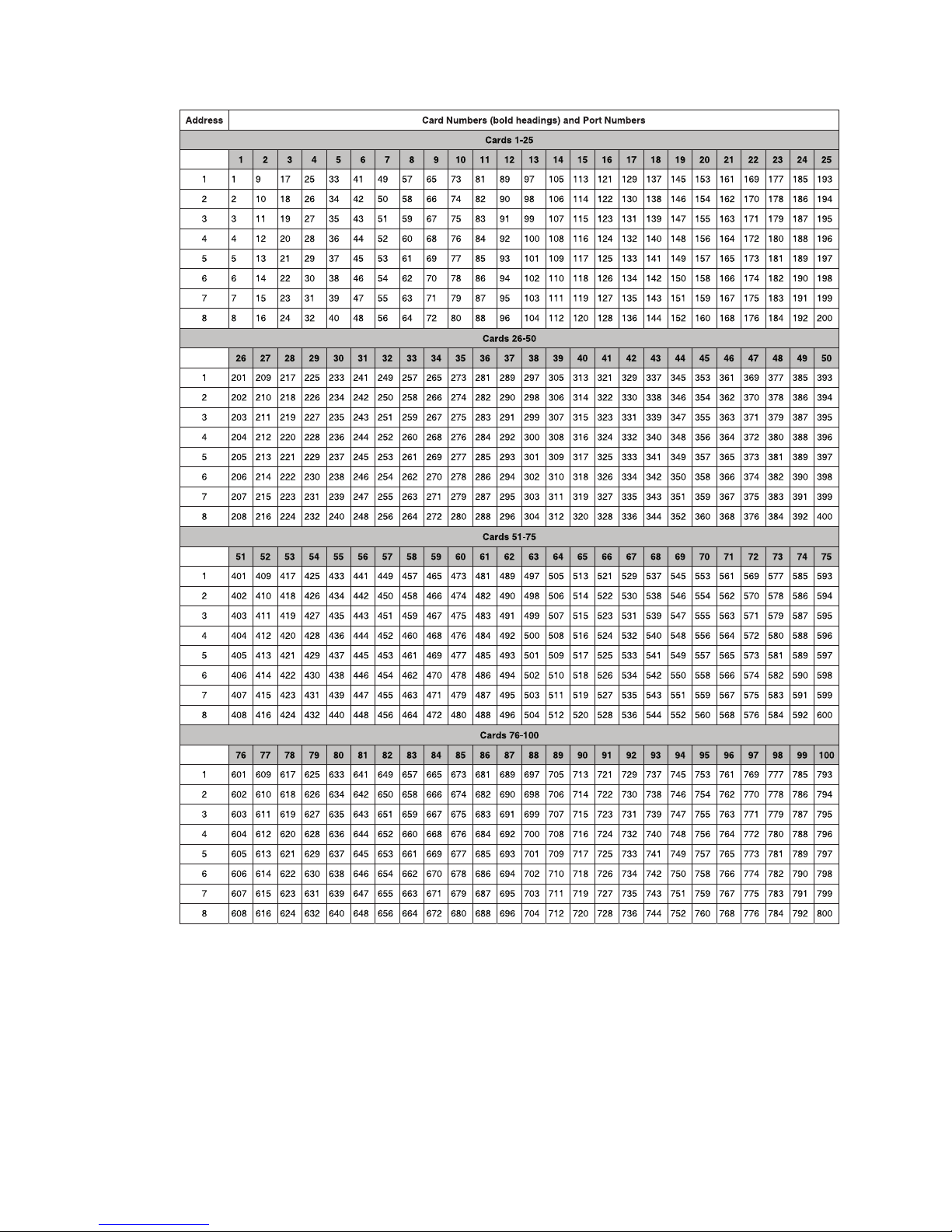
Figure 2.1
Address number vs intercom port numbers for 8-Port Audio I/O Cards (ADAM AND ADAM
CS Intercom Systems.
ADAM CS with 50-pin Telco back panel:
Determine the address setting from Figure 2.1. To use the table, locate the intercom port number
to which the KP-32 will be connected. Then, read across to the "Address" column to find the
Address number. Set the KP-32 Address switch to this number.
Note
Settings 0, and 9 through F are not used.
2-5
Address Setting for ADAM
Each Audio I/O card contains 1 group of 8 intercom ports. Determine the address setting from
Figure 2.1. To use the table, locate the intercom port number to which the KP-32 will be
connected. Then, read across to the "Address" column to find the Address number. Set the KP-32
Address switch to this number. Note: settings 0, and 9 through F are not used.
Connections
EXP. AND LCP Connectors
Connect from the Exp. connector on the back of the KP-32 to the Expansion 1 connector of an
optional EKP-32 Expansion Panel. Use the interconnect cable supplied with the Expansion Panel.
The Expansion 2 connector on the Expansion Panel can connect to a second Expansion Panel, but
no more than 64 intercom keys can be operated per intercom port.
Each LCP-32/16 adjusts the listen levels for 16 keypanel keys, and you can connect as many
LCP-32 panels as required to adjust all keys on the KP-32 and on an optional EKP-32 Expansion
Panel. An interconnect cable is supplied with each LCP-32. Connect the first LCP-32 to the LCP
connector on the KP-32. Connect the second LCP-32 to the first LCP-32, and so forth.
Note
When arranging LCP-32 panels in an equipment rack, you should put them directly above or
below the keys they will be used to adjust.
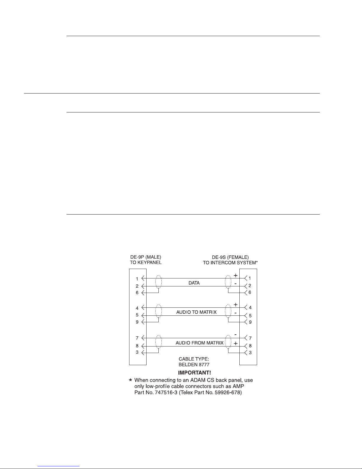
Frame Connector
Use either of the Frame connectors (but not both) to connect to an intercom port of the intercom
system. The intercom port you connect to should agree with the address that you set previously.
Cable wiring diagrams are shown in Figure 2.2 and Figure 2.3.
Figure 2.2
DE9S Intercom Cable Wiring
2-6 KP-32 User Manual
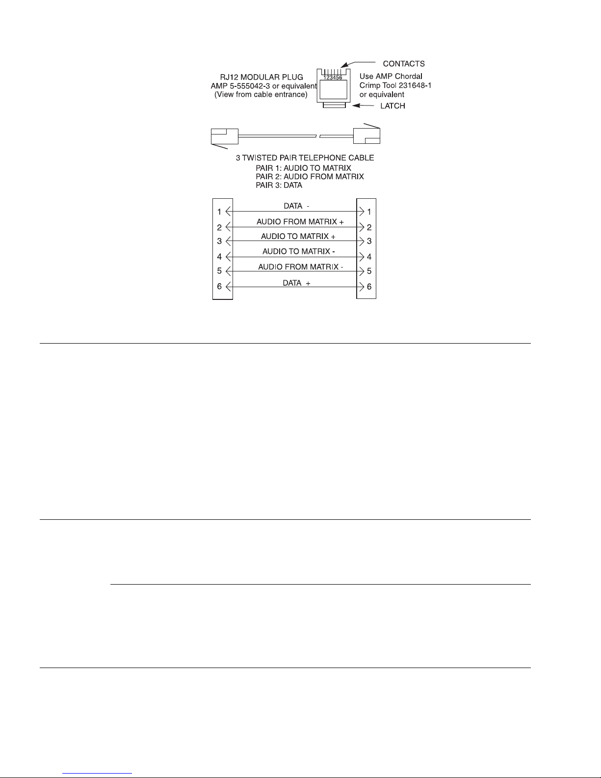
Figure 2.3
RJ12 Intercom Cable Wiring
Power Supply Connector
Align and insert the external power supply connector. Tighten the locking ring. Connect a power
cord to the power supply and to an AC power source. The power supply accepts 100-240 VAC,
50/60 Hz.
At power-up, the alphanumeric displays will first show asterisks (****). After several seconds to
a minute the intercom key assignments will display.
Note
If the keypanel cannot establish communication with the intercom system, all alphanumeric
displays will continue to show asterisks. Check the keypanel to matrix cable connection if this
occurs. If the keypanel loses communications with the intercom, it will not revert to ****’s for 30
seconds. Hence, if there is a short disruptionin the data communications, the panel will not show
****’s at all (although the panel my briefly display ----’s).
Headset Connector
A stereo headset may be connected for use along with or in place of the front panel speaker and a
separate microphone. Headphones may be connected for use with a separate microphone.
Headset Microphone Gain Adjustment
The gain of the headset microphone preamp can be adjusted via the recessed trim pot located on
the back panel. Turn the pot clockwise to increase gain and counter-clockwise to decrease gain.
The limits are ±20 dB from nominal.
Panel Microphone Connector
A panel microphone may be connected for talking with either the front panel speaker or
headphones used for listening. The connector accepts MCP5, MCP6, or MCP90 Panel

2-7
Microphones. Insert the microphone and rotate the entire microphone body several turns to lock
in place.
Panel Microphone Gain Adjustment
The gain of the panel microphone preamp can be adjusted via the recessed trim pot located on the
back panel. Turn the pot clockwise to increase gain and counter-clockwise to decrease gain. The
limits are ±20 dB from nominal.

2-8 KP-32 User Manual
This Page Left Blank Intentionally

3-1
S ECTION
3
C
HAPTER
3
B
ASIC
O
PERATION
Screen Saver Operation
If the KP-32 is set for screen saver operation, the alphanumeric display automatically shuts off
after several minutes of inactivity. The display reactivates on incoming call or when the keypanel
operator actuates any control. DIP switch 3 enables/disables screen saver operation.
Note
You can override the normal timeout period for screen saver operation and immediately place the
keypanel in screen saver mode. See "Service Menu, Disply Dim".
Selecting Headset or Speaker
Tap the Headset / Vol. Sel. key upward. The Vol. Sel. display alternates between
Hdst
and
Spkr
with each key tap. The Headset LED lights when the headset is selected and is off when the
speaker is selected.
Note
Future versions of ADAM Edit and Zeus Edit will be able to override the Headset or Speaker
setting.
Listen Volume Adjustments
By default, the Vol. control adjusts the listen volume for the speaker or headset, whichever
appears in the Vol. Sel. display. The level of auxiliary program inputs 1 & 2 (if GPI/O board is
present and Aux inputs are enabled) and the level of incoming audio from the intercom matrix can
be adjusted. To adjust a level, press the Vol. Sel. button until the desired source appears in the
Vol. Sel. display (
Aux1, Aux2, or Icom
). Then, use the Vol. control to adjust the listen volume. The
Vol. control defaults back to the speaker or headset after about one minute of inactivity of the
control. The minimum volume level for either the keypanel speaker or headset may be adjusted.
See “Service Menu, Min Volume”.
Note
You can save the volume adjustments to be the power-up defaults using "Service Menu, Save
Cfg".

3-2 KP-32 User Manual
Intercom Keys and Displays
Alphanumeric Display Indications for Intercom Keys
Upper Case Letters: Upper case letters indicate keys that have any kind of talk assignment, with
or without a corresponding listen assignment. Example:
DIR1
Lower Case Letters: Lower case letters indicate keys that have only a listen assignment. Example:
dir1
.
Dashes
----
: Dashes indicate a key that has no talk or listen assignment.
Flashing Alphanumeric Display: This means the key is activated to talk to an IFB, ISO, or TIF.
Note
The flashing alphanumeric display for TIF keys, remote IFB keys, and remote ISO keys can be
disabled by placing a check mark next to "Don't generate tallies for TIF and trunk use" in
ADAMedit (Options menu, Intercom Configuration, Options tab).
LED Indications for Intercom Keys
Note
Future versions of ADAM Edit can override LED indications.
Talk LED Indications
The talk LED is the lower LED for each key. The talk LED indications are as follows:
Continuous Green*
Talk is on and the keypanel operator can be heard at the destination.
Continuous Red Talk LED & Flashing Display Alpha ("In-use")*
The key is off, but someone is talking to the destination. This indication is provided for any local
PL, IFB, ISO, or TIF key. It does not apply to remote IFB or ISO keys. This indication is provided
so keypanels operators know when critical director communications are occurring. If you activate
the key, either of two things will happen:
• If you activate the key and the talk LED turns continuous green, this indicates that you and the
other keypanel operator are both talking to the destination.
• IFB keys only: If the talk LED flashes red when an IFB key is activated, this indicates that the
other keypanel has a higher IFB priority and you cannot talk at this time.
Note
The red "in-use" indication for TIF keys can be disabled in ADAMedit: In the ADAMedit
Options menu, select Intercom Configuration, then click on the Options tab. Place a check mark
next to "Don't generate talliesfor TIF and trunk use". Be sure to send the change to the intercom
system. Note that this will also disable the flashing alpha display when talking to remote IFBs or
ISOs as previously described.
Flashing Red Talk LED & Flashing Display Alternating Pattern of Alpha & (-**-)
("Busy")
You cannot talk at this time. This indication occurs when you activate a local IFB key that is
already in-use by a keypanel with a higher IFB priority. It also occurs when you activate any key
assigned to a remote destination, but there are currently no trunks available.
Note
Flashing red is also the intended indication when attempting to talk to a remote IFB while
someone else with a higher trunk IFB priority is already talking. However, this will require
ADAM MC version later than 9.9.x and Trunk MC version later than 7.x.x. As of this writing,
these versions are not implemented. Regardless of the indication provided, you will not be heard

3-3
at the remote location if your keypanel has the lower trunk IFB priority. IFB trunk priorities are
set in ADAMedit. (Click the "KP" button on the ADAMedit toolbar to access Keypanels / Ports
setup, then click the "Edit" button, then click the "Advanced" tab. Enter the desired IFB priority in
the fields provided. Be sure to send the change to the intercom system.)
Flashing Green Talk LED & Display Alpha (on time equal to off time)*
There is an incoming call from the destination assigned to the key. Activate the key to talk back.
Note
The duration of incoming call flash is controlled by DIP switch 4 on the KP-32 back panel. See
"Option Switch Settings" for further information.
Winking Green Talk LED (on time less than off time)*
This indicates that a key is ready to talk (key is on), but requires external footswitch activation to talk.
Listen LED Indication
The listen LED is the upper LED for each key. The listen LED is green when listen is on.
Intercom Key Operation
Basic Intercom Key Operation
The "up" position of an intercom key activates listen (if assigned). The "down" position activates
talk (if assigned). If there is no talk assignment for an intercom key, the talk position of the key
will not activate. If there is no listen assignment, the listen position will not activate.
For momentary activation of a key press and hold the key. Then, release it when finished.
For latching operation (if enabled) tap a key; it will turn on and remain on. Tap the key again to
turn it off when finished.
Note
Latching may be turned off for the entire keypanel by setting DIP switch 1 on the KP-32 back
panel to the Closed position. Latching may be disabled for individual keys on a keypanel using
ADAMedit: Click the KP button on the ADAMedit toolbar to open the Keypanels / Ports setup
screen. Select the intercom port where the keypanel is connected. Place a check mark in the "D"
check boxes for any keys where you want to disable latching. Be sure to send your changes to the
intercom system.
Operation of Intercom Keys with Auto Functions
Note
Assignment of keys with auto functions is described in the programming sections that follow.
Descriptions of the auto functions are also contained in the Glossary.
Operation of keys with auto functions is as follows:
Talk + auto follow
Talk and listen can be activated separately. The listen assignment listens to whatever is assigned
to the talk key.
Talk + auto listen
Both talk and listen will activate when talk is activated.
Talk + auto mute
Listen will turn off when talk is activated.

3-4 KP-32 User Manual
Talk + auto reciprocal
Listen will always be on, and talk may be turned on or off.
Talk + auto table
If an IFB talk key has an auto-table listen assignment, talk and listen can be independently
activated. The listen key listens to whatever is defined as the IFB Listen Source for the IFB that is
assigned to the talk key.
Note
A full explanation of the auto-table feature is beyond the scope of this manual. For further
information, search for "IFB" in ADAMedit help, then read the topics "IFB Auto Table
Description" and "IFB Setup Procedures".
All Call Key
Activating the key will also activate all keys to the left of it (up to, but not including another allcall key).
Talk + D I M
If a point-to-point key has the DIM function as a level 2 talk assignment, activating the key will
cause the crosspoint levels to diminish for any other intercom ports that are currently listening to
the same destination and that are in the same DIM table.
Note
A full explanation of DIM tables is beyond the scope of this manual. For further information,
search for "dim table" in ADAMedit help.
Operation of Intercom Keys with Options
Group Option Keys
Activating the master key in a key group will activate all keys in that group according to each
key's individual key assignment. Activating a slave key will not affect any other keys in the
group.
Solo Key
Activating a key that has the solo option will cause all other keys to turn off until the solo key is
again turned off.
Operation of Intercom Talk Keys with the Speaker DIM Setting
Activating any talk key will cause the speaker or headphone volume at this keypanel to diminish
by the amount specified in the Dim menu item on the Service menu.
Note
Do not confuse this with the Talk+DIM auto function previously described. Talk+DIM affects the
speaker or headphones on other keypanels when a particular talk key is activated on this
keypanel. Speaker DIM affects the speaker or headphone level on this keypanel when any talk
key on this keypanel is activated.
Operation of Intercom Keys assigned to TIF Ports
If an intercom key is assigned to talk to an intercom port that is designated as a TIF port in
ADAMedit, placing the key in the talk position will activate the KP-32 dialing menu. See
"TELEPHONE OPERATION" for further information.
Note
You designate an intercom port as a TIF port by checking the "Port is TIF" check box in
ADAMedit. (In ADAMedit, click the "KP" button on the toolbar to access Keypanels / Ports
setup, then select the intercom port where the TIF s connected, then click the "Edit" button, then

3-5
click the "Advanced" tab. Place a check next to "Port is TIF". Remember to send the change to the
intercom system.)
Muting the Microphone
Tap the MUTE key to turn microphone muting on or off.
The Vol. Sel. display alternates between
Hdst
and
Mute
(or between
Spkr
and
Mute
) while the
microphone is muted.
Note
While muting is on, you cannot be heard on the intercom, or by anyone on the telephone, or by
any device connected to the mic preamp output of the optional connector module.
Call Waiting Operation
Occasionally, a keypanel may call, and there won't be a key assigned to talk back to that caller. In
this case, the caller's name will appear in the Call waiting window. Press down and hold the Call
waiting key to talk back.
To clear a name from the Call waiting window, tap "up" on the Call waiting key.
If a second call is received in the Call waiting window while a caller name is already displayed,
the Call waiting LED will flash red. To answer the second call, tap "up" to clear the first name,
then hold the key down to talk to the second caller.
Note
By default, only the names of callers who are not currently assigned to intercom keys will appear
in the Call waiting window. Alternatively, you can force all caller names to display in the Call
waiting window. This is controlled either by DIP switch 2 on the ADAM Master Controller card
or by the ADAMedit check box titled "Always stack callers in call waiting window". (ADAMedit
Options menu, Intercom Configuration, Options tab. Note: the setting in ADAMedit overrides the
DIP switch 2 setting on the Master Controller card.) If your intercom system has mostly
keypanels with alphanumeric displays, we recommend that you do not stack all callers in the Call
waiting window.

3-6 KP-32 User Manual
This Page Left Blank Intentionally

4-1
S ECTION
4
C
HAPTER
4
T
ELEPHONE
O
PERATION
Note
Telephone operations require an optional TIF-951 Telephone Interface. Also, you must first
assign an intercom key to talk/listen to the TIF. We recommend a talk+auto listen assignment.
Receiving A Phone Call
When there is an incoming telephone call, the talk LED will flash red next to the KP-32 key that
is assigned to the TIF. Activate the key to answer the call.
Note
The red flash for incoming TIF call is the default operation. Alternatively, a continuous-red talk
LED indication can be provided. This is accomplished by checking the check box "Don't generate
tallies for TIF or trunk use" in ADAMedit (Options menu, Intercom Configuration, Options tab).
Note that this check box also affects other tally indications. For further information, press the F1
key while viewing the ADAMedit Options tab settings. Under the topic "Don't generate tallies for
TIF or trunk use" click on the "see table" link to view a table containing information about
operation with and without tally indications.
DIALING AND HANGING UP USING KP9X KEYPAD
SEQUENCES
KP9X Keypad Hang-up Sequence
1 Turn off the TIF talk key. (Tap "down" to toggle talk off. The talk LED should be off.)
2 On the keypad, tap PHONE CLR.
3 Momentarily turn the TIF talk key on, then off. The TIF key talk and listen indicators will turn
off and the TIF-951 "OFF" LED will activate.
Note
You can use the hang up sequence to hang up the TIF even if you did not place or answer the call.
KP9X Manual dial sequence
1 Activate the TIF listen key. (Tap "up" to toggle listen on. The listen LED should be on.)
2 Make sure the TIF talk key is off (Talk LED off).
3 On the keypad, tap CLR PHONE PGM.
4 Activate the TIF talk key. The talk LED turns green, the "ON" LED at the TIF-951 activates,
and you should hear dial tone at the KP-32.

4-2 KP-32 User Manual
5 Dial the telephone number. Digits scroll in the display above the TIF key.
6 When the far end answers, you can dial additional digits (to access a mail system or automated
response system, etc.). When finished dialing, momentarily turn off the TIF talk key to end
dialing mode (talk LED turns red).
7 Turn the TIF talk key back on for conversation.
8 To end the call:
1 Turn the TIF talk key off.
2 Tap PHONE CLR.
3 Tap the TIF talk key. The TIF key talk and listen indicators will turn off and the TIF-951
"OFF" LED will activate. The TIF-951 is now ready for another call.
KP9X Redial Sequence
Note
The last dialed phone number is always stored at the TIF and over-writes any previously dialed
phone number. If several people have access to the TIF, redial may not produce the results that
you expect!
1 Tap the PHONE key to activate dialing mode.
2 Tap "up" on the TIF key to activate listen.
3 Tap CLR 0 0 . The last phone number will redial.
4 After the number has dialed, click the PHONE key to end dialing mode.
5 If the far end answers, tap "down" on the TIF key to activate talk.
6 Use the KP9X hang-up sequence when finished with the call.
KP9X Autodial Sequences
Note
Unlike the autodial operations using the KP-32 menu system, which store telephone numbers
locally within the KP-32, the KP9X autodial operations work with telephone numbers that are
stored at the TIF-951. The advantage to saving at the TIF-951 is that many users can access a
common set of stored telephone numbers. A disadvantage is that users can easily over-write
important telephone numbers. Also, telephone numbers at the TIF-951 are stored in volatile
memory and will be lost if the TIF-951 loses power.
Storing an Autodial Number in the TIF-951
1 Tap the PHONE key.
2 Tap the TIF talk key to latch it on.
3 Using the number keys on the keypad, dial the phone number that you want to store. The entire
phone number sequence can have up to 30 digits.
Note
To insert one or more pauses anywhere in the dialing sequence, enter CLR CLR 9 9 for each
pause. A pause may be required, for example, if you need to enter a digit to get an outside line and
your phone system requires a pause before continuing to dial. If you are using credit card dialing,
several pauses may also be required between the phone number and your personal access code.
4 After dialing the telephone number, click CLR PGM, then enter a two-digit number (01, 02,
etc. up to 32) that you will use as the autodial number.
5 After storing the autodial number, hang up using the KP9X hang-up sequence.

4-3
Dialing an Autodial Number Stored in the TIF-951
1 Tap the PHONE key to activate dialing mode.
2 Tap "down" on the TIF talk key to latch it in the on position.
3 Tap CLR followed by the autodial number (01, 02, etc.).
4 When finished dialing, click the PHONE key again to exit dialing mode.
5 Hang up using theKP9X hang-up sequence.
DIALING AND HANGING UP USING THE KP-32 DIALING
MENU
The dialing menu will only activate when talking to an intercom port that has the "Port is TIF"
check box activated in ADAMedit. (In ADAMedit, click the "KP" button to access the
Keypanels/Ports screen, then select the port where the TIF-951 is connected, then click the "Edit"
button, then click the "Advanced" tab. Place a check mark next to "Port is TIF". Remember to
send this change to the intercom system.)
Manual Dialing
1 Turn on the TIF talk key.
ManualDial
displays in the Call waiting window.
2 Tap the PGM key.
Dial#?
displays, and the dial tone should be audible in your speaker or
headset.
Note
To hang up at any time after this point: tap the BACK key.
Hang up
will display, then tap PGM.
Note
While using the phone, any incoming intercom calls to the Call waiting window will go into the
call waiting stack. The caller names will not be displayed, but the Call waiting LED will flash red.
You may either hang up the phone and answer the intercom call, or continue with the phone call
and answer the intercom call afterward.
3 Dial the phone number. Digits appear in the Call waiting window as you dial. Dialing tones are
audible in the speaker or headset.
4 If the far end answers, begin your conversation.
Note
After the far end answers, you may dial additional digits (to retrieve voice mail, log onto an
automated answering system, etc.).
5 If there is no answer, or to hang up when finished talking, tap the BACK key.
Hang up
displays. Tap PGM to hang up.
Note
Occasionally, you may receive intercom caller names in the Call waiting window while you are
talking on the phone. In this case, the dialing menu options will be cleared from the Call waiting
window, and the
Hang up
option won't be available. Instead of trying to reenter the menu system,
use the "KP9X Keypad Hang-up Sequence".
Redial
Turn on the TIF talk key.
ManualDial
displays in the Call waiting window.
Tap the ↓↓ key until
Redial
displays.
Tap PGM.
If the far end answers, begin your conversation.

4-4 KP-32 User Manual
Note
After the far end answers, you may dial additional digits (to retrieve voice mail, log onto an
automated answering system, etc.).
5 If there is no answer, or to hang up when finished talking, tap PGM to hang up.
Note
Occasionally, you may receive intercom an intercom caller name in the Call waiting window
while you are talking on the phone. In this case, the dialing menu options will be cleared from the
Call waiting window, and the
Hang up
option won't be available. Instead of trying to reenter the
menu system, use the "KP9X Keypad Hang-up Sequence".
Autodial
Note
Autodial is only available after you have saved autodial numbers.
1 Turn on the TIF talk key.
ManualDial
displays in the Call waiting window.
2 Tap the ↓↓ key until
Auto Dial
displays.
NOTE: The Autodial menu only displays when a number has been programmed into the
Autodial Key Option.
3 Tap PGM.
4 Tap ↓↓ to select the desired autodial number, then tap PGM.
5 If the far end answers, begin your conversation.
Note
After the far end answers, you may dial additional digits (to retrieve voice mail, log onto an
automated answering system, etc.).
6 If there is no answer, or to hang up when finished talking, tap PGM to hang up.
Note
Occasionally, you may receive an intercom caller name in the Call waiting window while you are
talking on the phone. In this case, the dialing menu options will be cleared from the Call waiting
window, and the
Hang up
option won't be available. Instead of trying to reenter the menu system,
use the "KP9X Keypad Hang-up Sequence".
 Loading...