

Page 1

RTS ISDN 2002
System
Operator Manual
Software Description
Page 2

PAGE 1-2 RTS ISDN 2002 System
Page 3

RTS ISDN 2002 System PAGE 1-3
A Publication of
EVI Audio GmbH
Hirschberger Ring 45
D-94315 Straubing
Telephone + 49 9421 706-0
Fax + 49 9421 706-422
Email info@telex.de
Internet http://www.telex.de
Printed in Germany, January 2004
© EVI Audio GmbH 2004
All rights reserved. Reproduction in whole or in
parts is prohibited without the written consent of
the copyright owner.
The information contained in this publication is
accurate to the best of EVI knowledge. However,
EVI disclaims any liability resulting from the use
of this information and reserves the right to make
changes without notice.
Page 4

PAGE 1-4 RTS ISDN 2002 System
Page 5

RTS ISDN 2002 System PAGE 1-5
TABLE OF CONTENTS
1 Safety __________________________________________1-7
1.1 General Safety Requirements________________________ 1-7
1.2 Appearance of the safety instructions __________________ 1-7
1.2.1 Classification of safety instructions ____________________1-8
1.2.2 Warning symbols__________________________________ 1-9
2 Introduction ____________________________________ 2-10
3 Functionality ___________________________________ 3-11
4 System Description______________________________ 4-12
4.1 Mechanical Design _______________________________ 4-12
4.2 Functionality ____________________________________ 4-12
4.2.1 Mode 1: Telephone to key panel_____________________ 4-12
4.2.2 Mode 2: Key panel to Matrix ________________________ 4-13
4.2.3 Mode 3: Matrix to Matrix ___________________________ 4-13
4.2.4 Mode 4: Matrix to Matrix with Trunkmaster _____________ 4-13
5 Putting the System into Operation _________________ 5-14
5.1 Mounting _______________________________________ 5-14
5.2 Connection to the mains voltage_____________________ 5-14
5.3 Signalling LEDs__________________________________ 5-14
5.4 Configuration overview ____________________________ 5-15
6 OPERATION with a PC ___________________________ 6-16
6.1 Hardware requirements____________________________ 6-16
6.2 Connection of the RTS ISDN 2002 System to a PC ______ 6-16
6.3 Installation of the software on the PC _________________ 6-16
6.4 Main panel RTS ISDN 2002 Commander ______________ 6-17
6.4.1 Operating Mode 1: Telephone to key panel ____________ 6-17
6.4.2 Operating Mode 2: Key Panel to Matrix _______________ 6-21
6.4.3 Operating Mode 3: Matrix to Matrix___________________ 6-25
Page 6

PAGE 1-6 RTS ISDN 2002 System
6.4.4 Operating Mode 4: Matrix to Trunkmaster _____________6-29
6.4.5 Sub menu COM Port______________________________ 6-33
6.4.6 Sub menu System Panel___________________________ 6-34
6.4.7 Sub menu Software Download ______________________ 6-34
6.5 Menu Help______________________________________ 6-35
7 Dialling ________________________________________ 7-37
7.1 Via PC Software RTS ISDN 2002 Commander _________ 7-37
7.2 Via Front keys ___________________________________ 7-39
7.3 Via TTL inputs (USER I/O interface) __________________ 7-40
7.4 Via Telex Key panel (only Mode 1) ___________________7-41
8 Call acceptance _________________________________ 8-42
8.1 Automatic call acceptance (Auto answer on) ___________ 8-42
8.2 Via Front Keys___________________________________ 8-42
8.3 Via PC Software (Connect button) ___________________ 8-43
8.4 Via TTL Interface (USER I/O) _______________________ 8-43
8.5 Via Telex Key panel (only mode 1) ___________________8-43
9 INTERFACES ___________________________________ 9-44
9.1 Audio interfaces (AUDIO) __________________________ 9-44
9.2 Control interface (RS232C)_________________________ 9-45
9.3 RS232 Data Interface (DATA RS232)_________________ 9-45
9.4 RS 485 Data Interface (DATA) ______________________ 9-46
9.5 TTL Interface (USER I/O) __________________________ 9-46
9.6 ISDN (BRI) Interface (S0 1) ________________________ 9-47
10 TROUBLE Shooting ____________________________ 10-48
11 Cabling _______________________________________ 11-49
11.1 Matrix Connection Cable__________________________ 11-49
11.2 Key Panel Connection Cable ______________________ 11-50
Page 7

RTS ISDN 2002 System PAGE 1-7
1 SAFETY
The unit described is designed against the latest technical parameters and
complies with all national and international safety requirements. It operates
with a high level of operational safety resulting from long development experience and stringent quality control in our company.
In normal operation this equipment is safe.
There are, however, some potential sources of danger that cannot be completely eliminated.
This Operator Manual therefore contains basic safety instructions that must be
observed during system configuration and operation. This Operator Manual
must be read before the system is used and the current version of the document must always be kept close to the equipment.
All safety instructions have a uniform appearance. This appearance is described in detail in CHAP. 1.2 .
1.1 General Safety Requirements
In order to keep the technically unavoidable residual risk to a minimum, it is
imperative to observe the following rules:
• Transport, storage and operation of the unit/system must be under the
permissible conditions only.
• Installation, configuration and disassembly must be carried out only by expert personnel and with reference to the respective documentation.
• The system must be operated by expert and authorised users only.
• The system must not be operated unless it is in perfect working order.
• Any conversions or changes to the system or parts of the system (includ-
ing the software) must be carried out by qualified personnel from our company or by expert personnel authorised by our company.
All changes carried out by other persons lead to a complete exemption
from liability.
• The removal or disabling of safety facilities, the clearing of faults and errors, and the maintenance of the equipment must be carried out by specially qualified personnel only.
• Non-system software is used at one´s own risk. The use/installation of
non-system software can adversely affect the normal functioning of the
system software.
• Only use tested and virus-free data carriers!
1.2 Appearance of the safety instructions
All safety instructions include a signal word that classifies the danger and a
text block that contains descriptions of the type and cause of the danger, the
consequences of ignoring the safety instruction and the measures that can be
Page 8
PAGE 1-8 RTS ISDN 2002 System
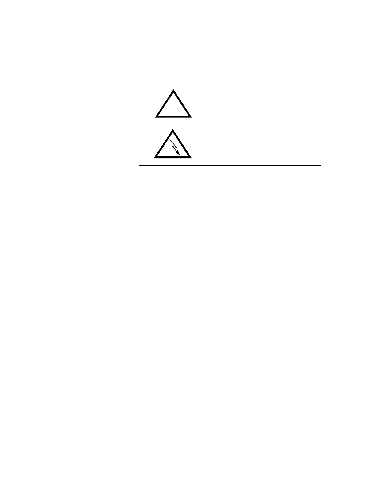
taken to minimise the danger. In some safety instructions, a warning symbol is
placed underneath the signal word (see also CHAP. 1.2.2):
Signal word
!
Type and cause of danger
Possible Consequences of ignoring the safety in-
struction
Measures to minimise the danger
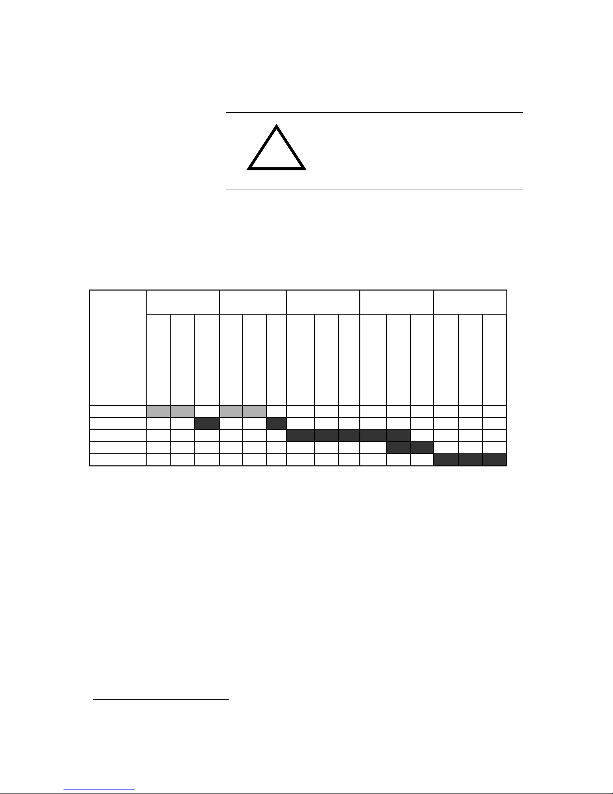
1.2.1 Classification of safety instructions
There are five classes of safety instructions: "Danger", "Warning", "Caution",
"Notice" and "Important". The classification is shown in the following table.
Result
Death Serious injury Minor injury Material damage
1
Fault
2
Signal word
d
e
f
i
n
i
t
e
l
i
k
e
l
y
p
o
s
s
i
b
l
e
d
e
f
i
n
i
t
e
l
i
k
e
l
y
p
o
s
s
i
b
l
e
d
e
f
i
n
i
t
e
l
i
k
e
l
y
p
o
s
s
i
b
l
e
d
e
f
i
n
i
t
e
l
i
k
e
l
y
p
o
s
s
i
b
l
e
d
e
f
i
n
i
t
e
l
i
k
e
l
y
p
o
s
s
i
b
l
e
DANGER
3
WARNiNG
CAUTION
NOTICE
IMPORTANT
The signal word "Note" is also used in the Operator Manual. Text passages
marked in this way do not describe a danger, but rather contain reminders,
tips and general information to ensure optimum operation of the system.
1
Damage to product or product environment
2
Considerable impairment to operation
3
This danger class is not required for TITAN Micro
Page 9
RTS ISDN 2002 System PAGE 1-9
1.2.2 Warning symbols
The following warning symbols are used:
Symbol Meaning
!
General warning about a danger
Warning about a dangerous electrical voltage
The safety instructions classified "Danger", "Warning" and "Caution" always
include a warning symbol. "Notice" and "Important" safety instructions sometimes include a warning symbol.
Page 10

PAGE 2-10 RTS ISDN 2002 System
2 INTRODUCTION
The RTS ISDN 2002 System incorporates two Audio codecs according to
G.711 and G.722 coding algorithms for bi-directional communication. The
coding delay of the 7-kHz G.722 coding algorithm is less than 10ms. The two
Audio codecs included in the system can be configured as 3.1-kHz (G.711) or
7-kHz (G.722) Audio codecs. Each coded Audio signal occupies a single
ISDN B channel (64-kbit/s channel). Therefore both codecs are using 2 B
channels of the S
o
interface. In the 7-kHz coding mode also a data signal can
be transmitted. Two different types of data interfaces are available. In the
G.711 Telephone mode the system detects the DTMF tones received from a
standard Telephone set and converts the tones into the Telex protocol for the
control of Matrix units. The system can be configured as 2 x G.711 Audio
codecs with two separate Audio interfaces but one common RS485 data interface. In the 7-kHz (G.722) Audio codec mode a RS232 and a RS485 data
channel are available. These data channels can be used for the interconnection of a Matrix unit to a Trunkmaster system.
Page 11

RTS ISDN 2002 System PAGE 3-11
3 FUNCTIONALITY
After the connection to the partner system is established audio and data
transmission starts immediately. Is the 7-kHz coding standard on both systems configured both systems run in the 7-kHz mode.
For remote control of Telex Intercom equipment four operating modes are
available.
Mode 1 supports a communication with a standard telephone set and transmits the received DTMF tones to the Telex Intercom equipment for remote
control.
In Mode 2 a 7-kHz connection can be established and a RS485 data channel
can be used for remote control of a Matrix by key panels.
In Mode 3 two Matrix units can be interconnected.
In Mode 4 Matrix units are interconnected and audio signals can be routed
controlled by a Trunkmaster unit. For this purpose the data interfaces of the
Matrix units are connected over the RTS ISDN 2002 System to the Trunkmaster system.
Page 12
PAGE 4-12 RTS ISDN 2002 System
4 SYSTEM DESCRIPTION
4.1 Mechanical Design
The RTS ISDN 2002 System is a 19” unit with 1 unit in high with the dimensions (W x H x D) 449 mm x 44 mm x 275 mm. RTS ISDN 2002 System can
be installed as a table top unit or in 19" racks. Sufficient ventilation is ensured
by ventilation holes located on the top and bottom of the housing.
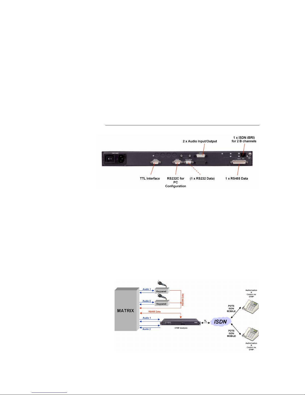
Figure 1 shows the rear view of the RTS ISDN 2002 System.
Figure 1: Rear view of RTS ISDN 2002 System
The RTS ISDN 2002 System is powered by an integrated power supply unit.
with AC voltages between 90V and 253V (nominal voltage range 230-240V).
The mains frequency can also vary between 50 and 60 Hz. The maximum
power consumption is approx. 20 W. The equipment also has 6 LEDs on the
front panel which are used for status indication of the system. The configuration of the system will be done by a PC via the control Interface (RS232) at the
rear side of the unit.
4.2 Functionality
The RTS ISDN 2002 System provides 4 operating modes
4.2.1 Mode 1: Telephone to key panel
Page 13
RTS ISDN 2002 System PAGE 4-13
In this operating mode two Telephone sets can dial a RTS ISDN 2002 system.
Via the DTMF tones of the telephones the key panels can remotely be controlled. The system converts the received DTMF tones into the Telex
protocol.
4.2.2 Mode 2: Key panel to Matrix
At both sides RTS ISDN 2002 products are installed. The RS485 commands
are transmitted between Matrix and remote key panels by the RTS ISDN 2002
system. The Audio transmission quality is 7-kHz
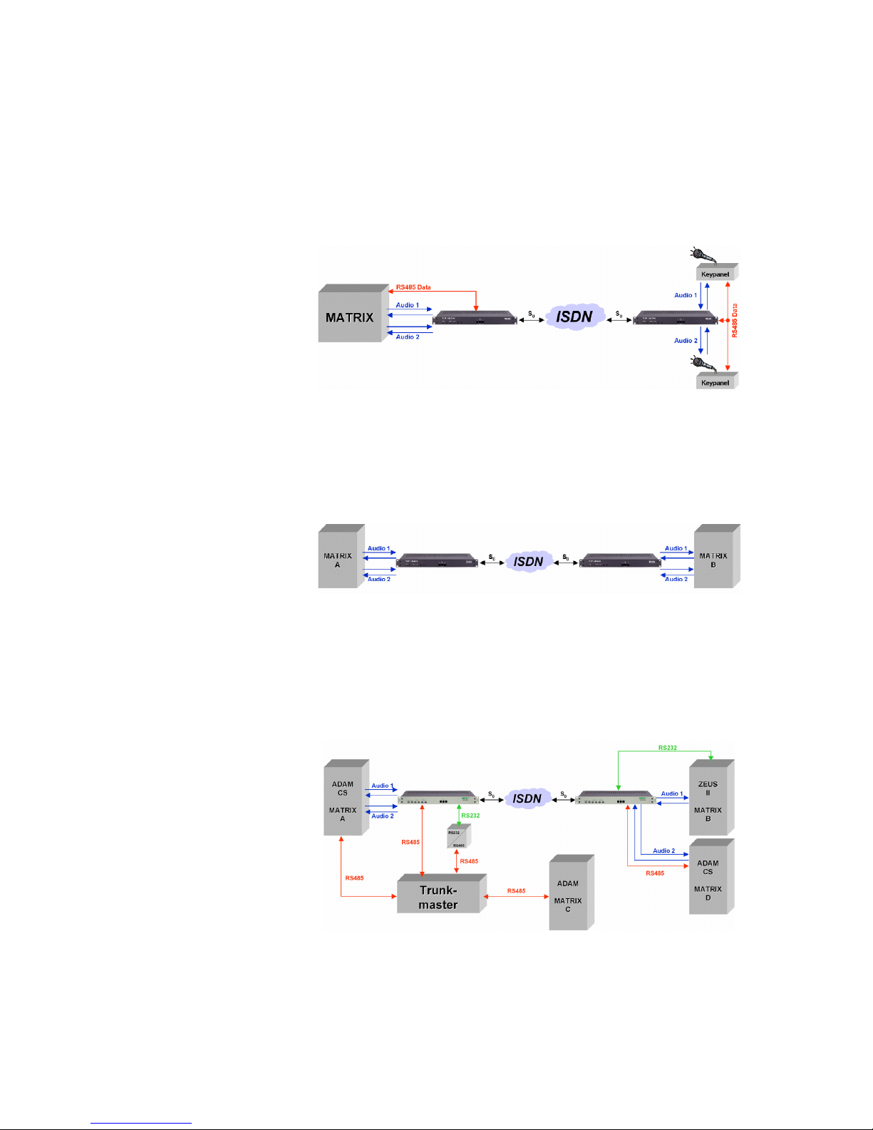
4.2.3 Mode 3: Matrix to Matrix
Matrix units are interconnected by 7-kHz transmission channels. Only Audio
signals are transmitted.
4.2.4 Mode 4: Matrix to Matrix with Trunkmaster
In addition to Mode 3 also one RS232 and one RS485 data channel from the
remote Matrix can be transmitted to the Trunkmaster.
Page 14

PAGE 5-14 RTS ISDN 2002 System
5 PUTTING THE SYSTEM INTO OPERATION
5.1 Mounting
With its dimensions (W x H x D) of 449 mm x 44 mm x 275 mm the RTS ISDN
2002 System can be operated as a table-top device or, be inserted into 19"
racks.
The dimensions given above are valid for the table-top version with no feet. If
the RTS ISDN 2002 System is to be inserted into a rack, it should be remembered that the bending radius of the cables should always be greater than the
minimum allowed value.
If the RTS ISDN 2002 System is installed in a rack, it should also be ensured
that sufficient ventilation is provided. It is recommended that at least 1 cm
space is left next to the openings. As rule, the ambient temperature should not
lie outside the range +5°C to +40°C. These limits are of particular importance
if the system is inserted in a rack.
During operation, the humidity must lie between 5% and 85%.
NOTICE
!
Incorrect ambient temperature and humidity can lead
to equipment failure
Operation of the unit outside the above limits invali-
dates the warranty.
The RTS ISDN 2002 System must therefore be oper-
ated within the specified limits.
5.2 Connection to the mains voltage
The integrated power supply unit of the RTS ISDN 2002 System can be operated with a voltage (mains) between 90 V and 253 V. The mains frequency
can vary between 50 Hz and 60 Hz. The power consumption is a maximum of
approx. 20 W.
After putting the unit into operation, the “POWER” LED should light up. An internal reset is then triggered. This is indicated by a blinking “ALARM” LED.
After approximately twenty seconds, the unit is operational and the red
"Alarm" LED should stop blinking.
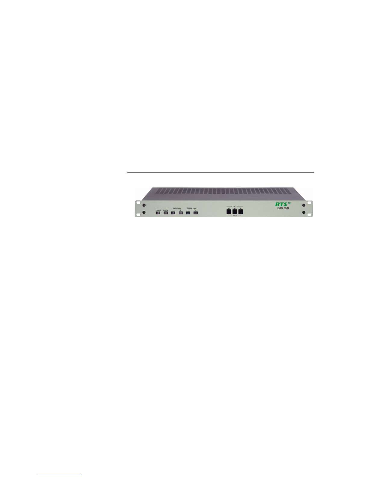
5.3 Signalling LEDs
There are six LEDs for signalling on the RTS ISDN 2002 System
(see Figure 2):
• Power: green
Lights up when system is powered.
• Alarm: red
Lights up if a fault has occurred in the unit.
Page 15
RTS ISDN 2002 System PAGE 5-15
• DATA CALL 1 : green
Is slow flashing if an outgoing call is initiated
Is fast flashing if an incoming call is detected
Lights up if a 7-kHz Audio connection is established for Codec 1
• DATA CALL 2 : green
Is slow flashing if an outgoing call is initiated
Is fast flashing if an incoming call is detected
Lights up if a 7-kHz Audio connection is established for Codec 2
• PHONE CALL 1 : orange
Is slow flashing if an outgoing call is initiated
Is fast flashing if an incoming call is detected
Lights up if a 3.1-kHz Audio connection is established for Codec 1
• PHONE CALL 2 : orange
Is slow flashing if an outgoing call is initiated
Is fast flashing if an incoming call is detected
Lights up if a 3.1-kHz Audio connection is established for Codec 2
Figure 2: Front view of RTS 2002 System
5.4 Configuration overview
This chapter shall give an overview of the configuration of the system. Detailed instructions are described in the following chapters.
1. Connection of Audio and data signals depending on the operation mode
2. Connection of the unit to the ISDN network
3. Loading of the Windows application software RTS ISDN 2002 (see chap-
ter. 6.3) and configuration of the PC (see chapter 6.4.5)
4. Configuration of the Audio Codec 1
5. Configuration of the Audio Codec 2
6. Entering the ISDN numbers and dial up
7. Checking the establishing of the connection.
Page 16

PAGE 6-16 RTS ISDN 2002 System
6 OPERATION WITH A PC
The Windows control software „RTS ISDN 2002“ allows a simple configuration
and control of the system.
6.1 Hardware requirements
The PC must fulfil the following minimum requirements:
• IBM PC AT, IBM PS/2 or 100% compatible
• Windows 98, 2000, XP
• approx. 1,5 MB free hard-disk memory
• a free serial interface RS-232
• Microsoft, IBM PS/2 or 100% software-compatible mouse
6.2 Connection of the RTS ISDN 2002 System to a PC
Connect the PC serial interface to the CONTROL (RS232C) interface on the
rear panel of the RTS ISDN 2002 System. Use a RS232 cable (9-pin SUB-D
DIN to 9-pin SUB-D cable).
The serial interface of RTS ISDN 2002 (RS232C) is configured in accordance
with the following parameters by the factory:
• Data signal
• 19200 Baud
• 8 data bits
• no parity
The RTS ISDN 2002 System can now be controlled from the PC.
6.3 Installation of the software on the PC
For the installation 1 of the software on the PC, please place the disk in the
drive of the PC. Then start the installation under Windows by selecting the
START button and selecting the sub menu item Command.... Insert into the
command line
a:setup
and select OK button. If your disk drive is not "a", use the corresponding designation in place of "a", Now follow the remarks of the installation program and
use the recommended directory. As proposed please install a new program
group „RTS ISDN 2002“. In this program group you will find later the symbol
for starting the program as well as a possibility for de-installation of the program.
1
Please make a backup copy of the original disk before installation.
Page 17

RTS ISDN 2002 System PAGE 6-17
Uninstall
After successful installation you will find now under START → PROGRAMME
→RTS ISDN 2002: Icon for starting the RTS ISDN 2002 software.
For de-installation select the icon
6.4 Main panel RTS ISDN 2002 Commander
After starting the software the user will get displayed the main panel. The main
panel indicates the status of the
- PC connection
- ISDN connection
- Audio Codec operating modes
- Data channel interfaces
- Operating mode
In the main panel the telephone book for ISDN destination can be operated
and calls can be initiated.
For the different operating modes different panels are displayed.
6.4.1 Operating Mode 1: Telephone to key panel
Mode 1 supports communication with standard telephone units and transmits
the received DTMF tones to the Telex Intercom equipment for remote control.
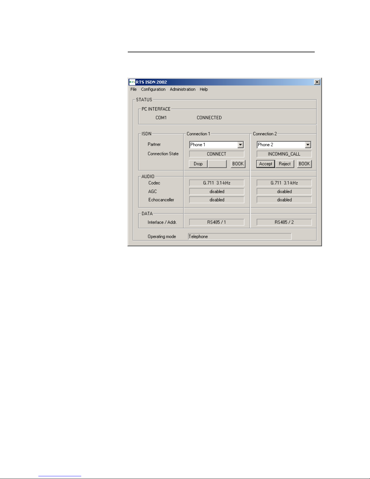
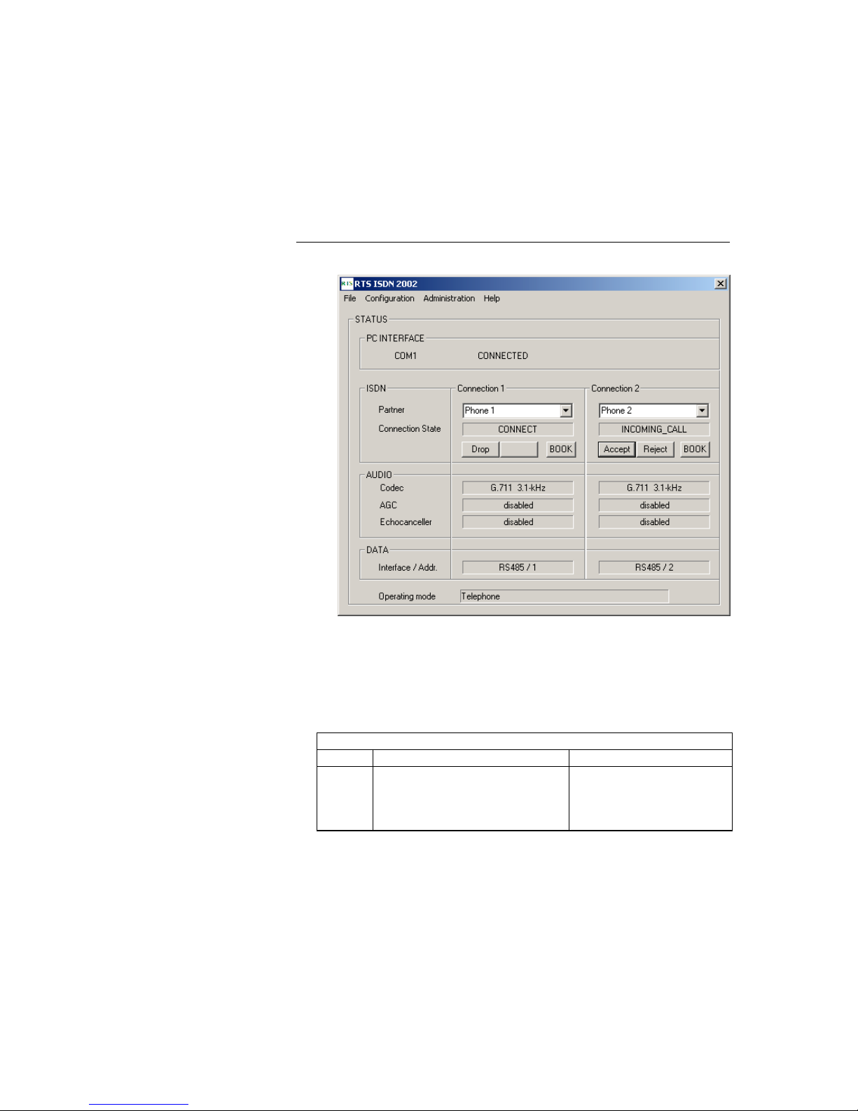
6.4.1.1 Mode 1: Main panel
All necessary settings for Audio Codec 1 and Audio Codec 2 are indicated in a
common panel.
• The field PC INTERFACE displays the selected COM port and the status
the connection (CONNECTED or NOT CONNECTED).
• In the field ISDN the Connection State shows the status of the connection,
such as CONNECT, INCOMING_CALL, NOT_CONNECTED
• Connected calls can be disconnected using the Drop button or incoming
calls can be accepted selecting the Accept button or rejected selecting the
Reject button.
• The selection of the BOOK button opens a Telephone Book stored on the
PC
• In the Field AUDIO the coding algorithms of the Audio codecs (G.711 3.1-
kHz ) and the status of the AGC and Echo Canceller (enabled or dis-
abled) are displayed
• In the field DATA (Interface/Addr.)the RS485 data interface together with
its address for codec 1 and 2 are indicated
• Operating mode shows Telephone for Mode 1
Page 18
PAGE 6-18 RTS ISDN 2002 System
Figure 3: Mode 1: Main panel RTS ISDN 2002 System
Page 19

RTS ISDN 2002 System PAGE 6-19
6.4.1.2 Mode 1: Configuration panel for ISDN and Data
Figure 4: Mode 1: Configuration panel for ISDN and Data
• In the COMMON SETTINGS Field the Operating Mode can be selected . If
the Telephone mode is chosen the Line Mode is fixed to ISDN dial up
line
• In the field ISDN the MSN number for each connection can be inserted
also the Auto Answer function can be selected with a given answering
time.
• In the RS485 Field the RS 485 address for each Audio channel must be
entered. Valid addresses are 1 ... 8.
• The Field DATA is not valid for operating mode 1.
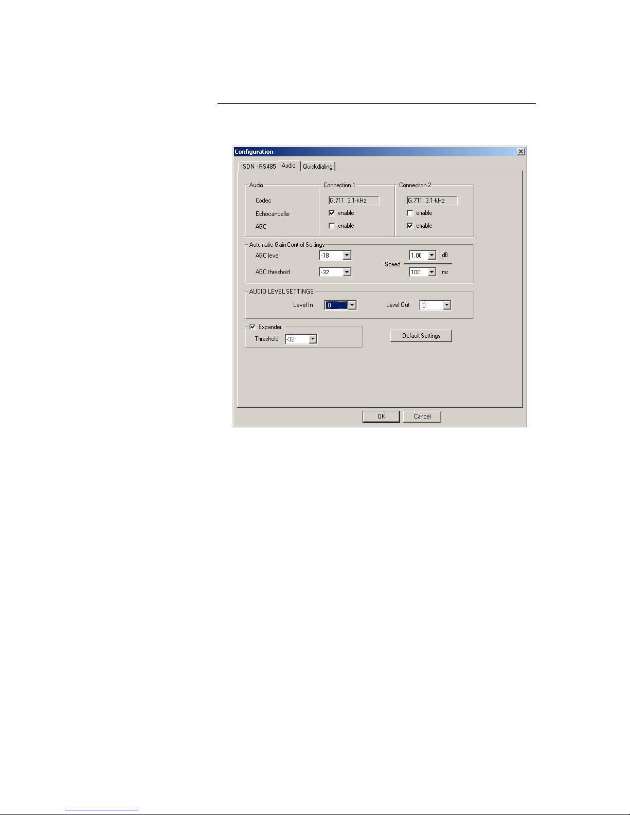
6.4.1.3 Mode 1: Configuration panel for Audio
• In the Audio Field the coding algorithms G.711 3.1-kHz of Audio codec 1
and Audio codec 2 are displayed. For each Audio codec an Echo Canceller and an AGC can be enabled.
• In the field Automatic Gain Control Settings the AGC level, the AGC
threshold and the Speed can be defined. But if possible use the default
settings.
• In the AUDIO LEVEL SETTINGS Field the nominal level of the Audio in-
terfaces can be defined.
• In the Field Expander the Threshold value can be inserted
Page 20
PAGE 6-20 RTS ISDN 2002 System
• If not sure select Default Settings. In this case all levels will be set to op-
erative values
Figure 5: Mode 1: Configuration panel for Audio
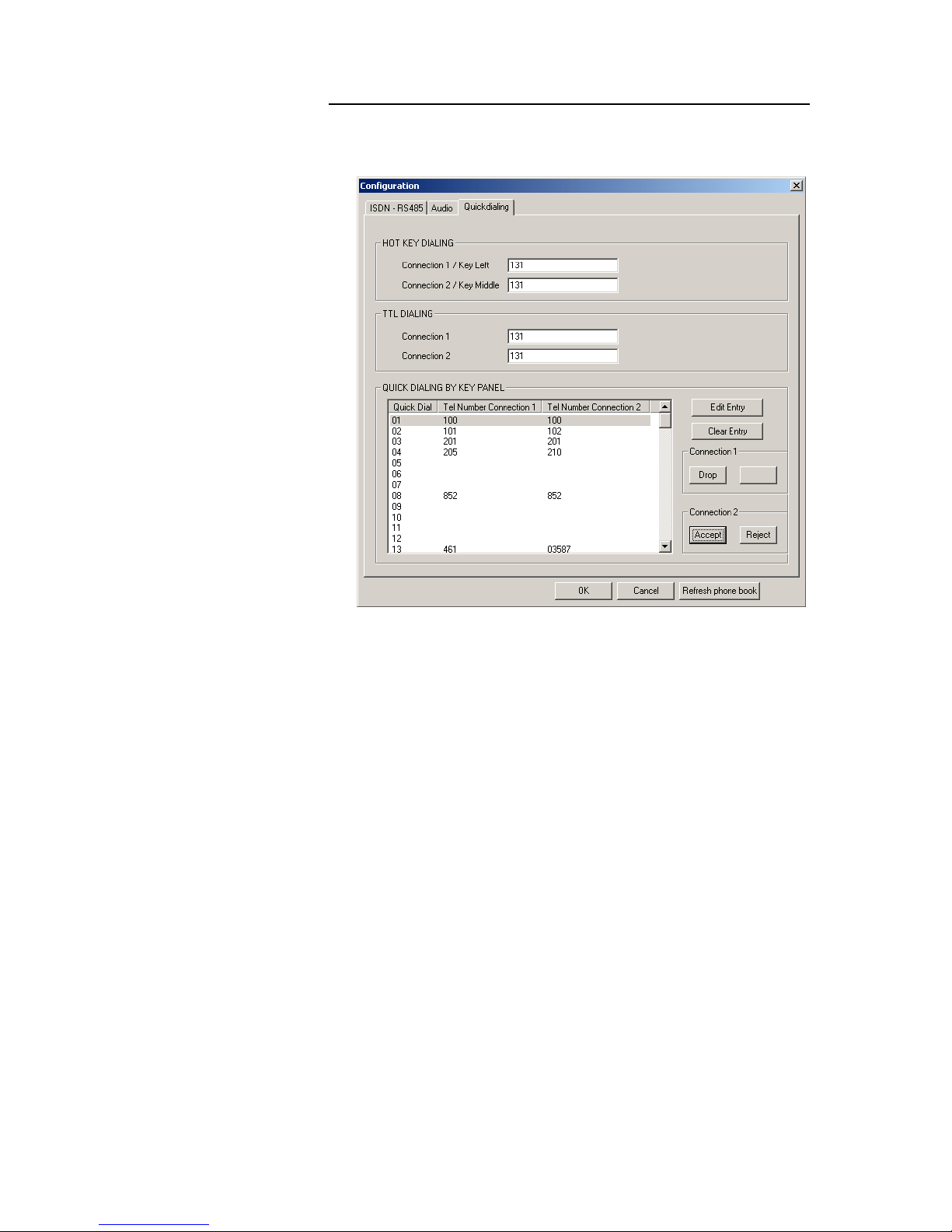
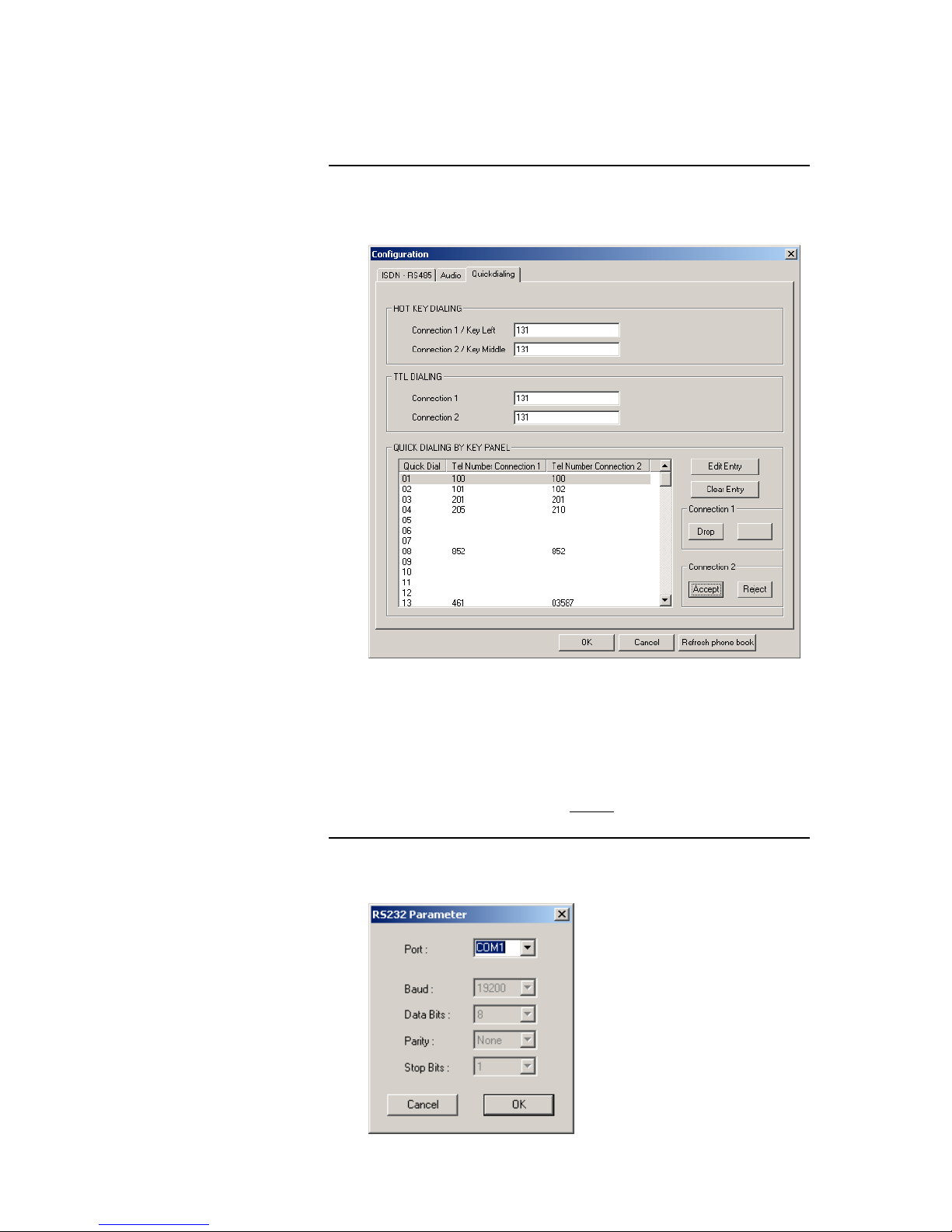
6.4.1.4 Mode 1: Configuration panel for Quick Dialling
• In the HOT KEY DIALLING Field the ISDN telephone numbers for con-
nection 1 for codec 1 and connection 2 for codec 2 can be entered.
Connection 1 can be dialled with the left key on the front and connection 2
can be dialled with the middle key on the front.
• In the field TTL Dialling the ISDN telephone numbers can be adjusted to
the TTL inputs for Audio codec 1 and 2
• In the QUICK DIALLING BY KEY PANEL Field ISDN telephone numbers
can be inserted and can be adjusted to Key Panel Quick Dial Codes. With
the button Refresh Phone Book all stored numbers are loaded from the
RTS ISDN 2002 System
Page 21
RTS ISDN 2002 System PAGE 6-21
Figure 6: Mode 1: Configuration panel for Quick dialling
6.4.2 Operating Mode 2: Key Panel to Matrix
In Mode 2 two 7-kHz connections can be established and a RS485 data
channel can be used for remote control of a Matrix by key panels.
6.4.2.1 Mode 2: Main panel
All necessary settings for Audio Codec 1 and Audio Codec 2 are indicated in a
common panel.
• The field PC INTERFACE displays the selected COM port and the status
of the connection (CONNECTED or NOT CONNECTED).
• In the field ISDN the Connection State shows the status of the connection,
in this case the ISDN leased line mode is configured. If there is no connection NO SIGNAL is indicated
• The selection of the BOOK button opens a Telephone Book stored on the
PC
• In the Field AUDIO the coding algorithms of the Audio codecs (G.722 7-
kHz ) are displayed . In this operating mode AGC and Echo Canceller are
disabled
Page 22

PAGE 6-22 RTS ISDN 2002 System
• In the field DATA (Interface) the same RS485 data interface is displayed
for both Audio Codecs
• Operating mode shows Remote Keypanel for Mode 2
Figure 7: Mode 2: Main panel RTS ISDN 2002 System
Page 23

RTS ISDN 2002 System PAGE 6-23
6.4.2.2 Mode 2: Configuration panel for ISDN and Data
Figure 8: Mode 2: Configuration panel for ISDN and Data
• In the COMMON SETTINGS Field the Operating Mode such as Remote
Keypanel and the Line Mode such as ISDN dial up line or ISDN leased
line for connection 1, connection 2 and connection 1 + 2 can be selected
• In the field ISDN the MSN number for each connection can be inserted
also the Auto Answer function can be selected with a given answering
time.
• In the RS485 Field the RS 485 address for each Audio channel is not
valid in this operating mode.
• The Field DATA is not valid for operating mode 2.
6.4.2.3 Mode 2: Configuration panel for Audio
• In the Audio Field the coding algorithms G.722 7-kHz of Audio codec 1
and Audio codec 2 are displayed. In this Mode Echo Canceller and AGC
can not be enabled.
• In the field Automatic Gain Control Settings also the AGC level, the
AGC threshold and the Speed can not be defined.
• In the AUDIO LEVEL SETTINGS Field the nominal levels of the audio
interfaces can be defined
• In the Field Expander the Threshold value can not be inserted
• If not sure select Default Settings. In this case all levels will be set to op-
erative values
Page 24

PAGE 6-24 RTS ISDN 2002 System
Figure 9: Mode 2: Configuration panel for Audio
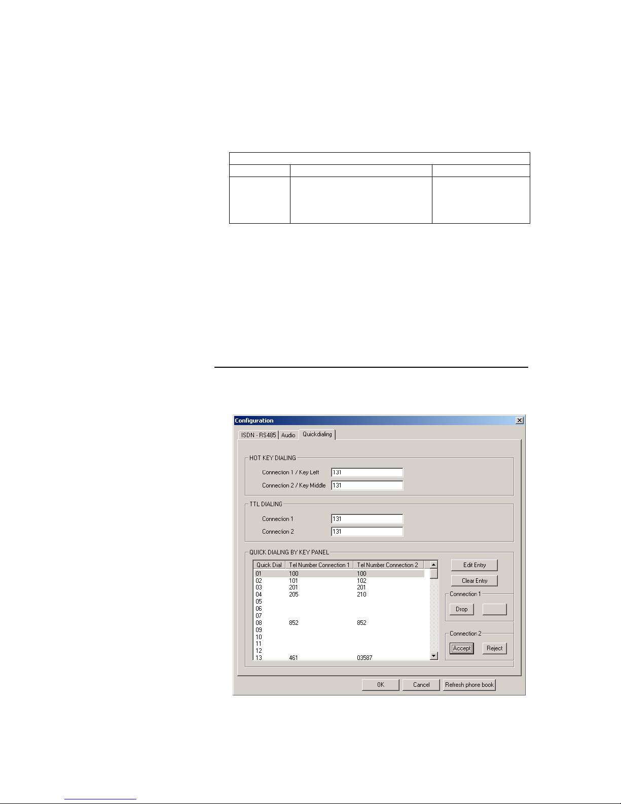
6.4.2.4 Mode 2: Configuration panel for Quick Dialling
• In the HOT KEY DIALLING Field the ISDN telephone numbers for con-
nection 1 for codec 1 and connection 2 for codec 2 can be entered.
Connection 1 can be dialled with the left key on the front and connection 2
can be dialled with the middle key on the front.
• In the field TTL Dialling the ISDN telephone numbers can be adjusted to
the TTL inputs for Audio Codec 1 and 2
• In the QUICK DIALLING BY KEY PANEL Field ISDN telephone numbers
can be inserted and can be adjusted to key Panel Quick Dial Codes and
with the button Refresh the Phone Book can be loaded from the unit. This
function is only available in Mode 1, but can be prepared also in the other
operating modes.
Figure 10: Mode 2: Configuration panel for Quick dialling
Page 25

RTS ISDN 2002 System PAGE 6-25
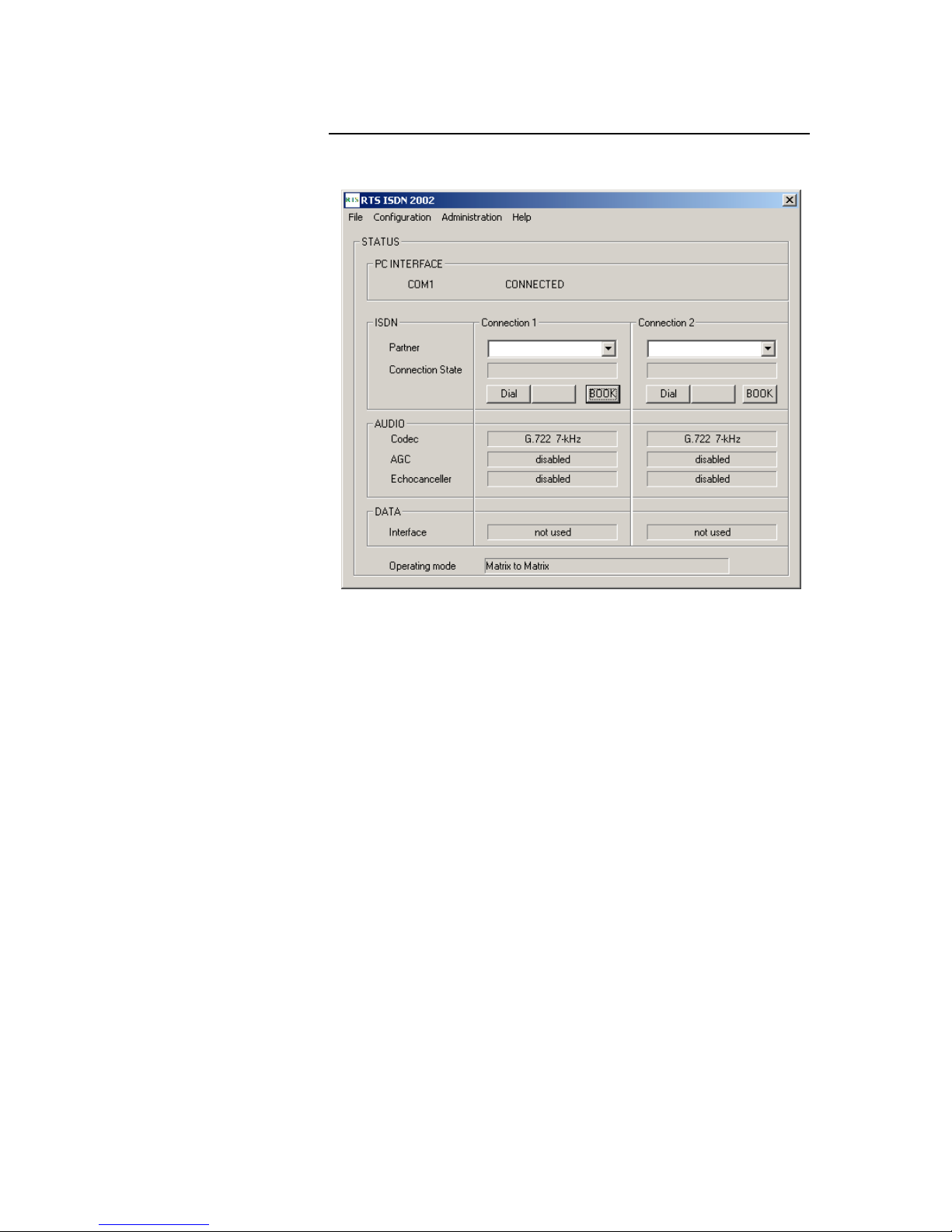
6.4.3 Operating Mode 3: Matrix to Matrix
In Mode 3 two Matrix units can be interconnected.
6.4.3.1 Mode 3: Main panel
All necessary settings for Audio Codec 1 and Audio Codec 2 are indicated in a
common panel.
• The field PC INTERFACE displays the selected COM port and the status
of the connection (CONNECTED or NOT CONNECTED).
• In the field ISDN the Connection State shows the status of the connection,
in this case the ISDN leased line mode is configured. If there is no connection NO SIGNAL is indicated
• The selection of the BOOK button opens a Telephone Book stored on the
PC
• In the Field AUDIO the coding algorithms of the Audio codecs (G.722 7-
kHz ) are displayed. In this operating mode AGC and Echo Canceller are
disabled
• Operating mode shows Remote Keypanel for Mode 3
Page 26
PAGE 6-26 RTS ISDN 2002 System
Figure 11: Mode 3: Main panel RTS ISDN 2002 System
Page 27
RTS ISDN 2002 System PAGE 6-27
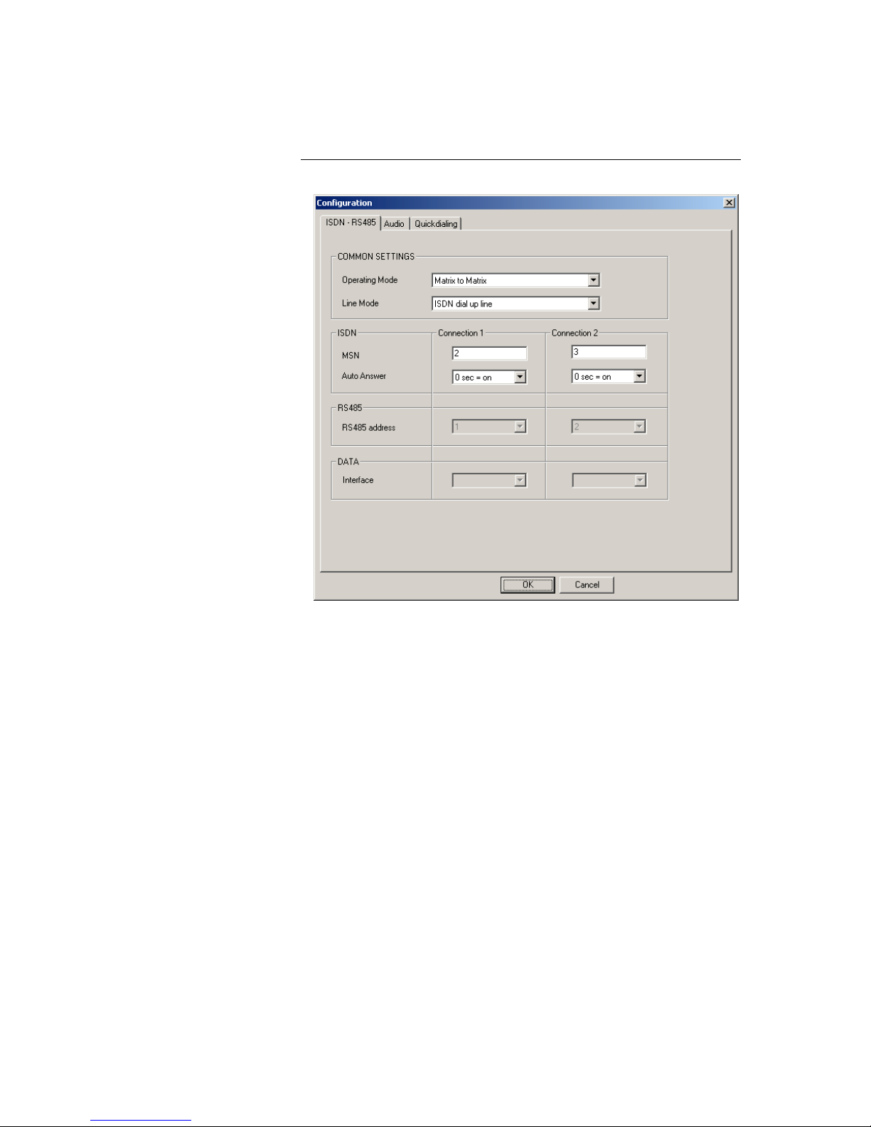
6.4.3.2 Mode 3: Configuration panel for ISDN and Data
Figure 12: Mode 3: Configuration panel for ISDN and Data
• In the COMMON SETTINGS Field the Operating Mode such as Matrix to
Matrix and the Line Mode such as ISDN dial up line or ISDN leased line
can be selected
• In the field ISDN the MSN number for each connection can be inserted
also the Auto Answer function can be selected with a given answering
time.
• In the RS485 Field the RS 485 address for each Audio channel is not
valid in this operating mode.
• The Field DATA is not valid for operating mode 3.
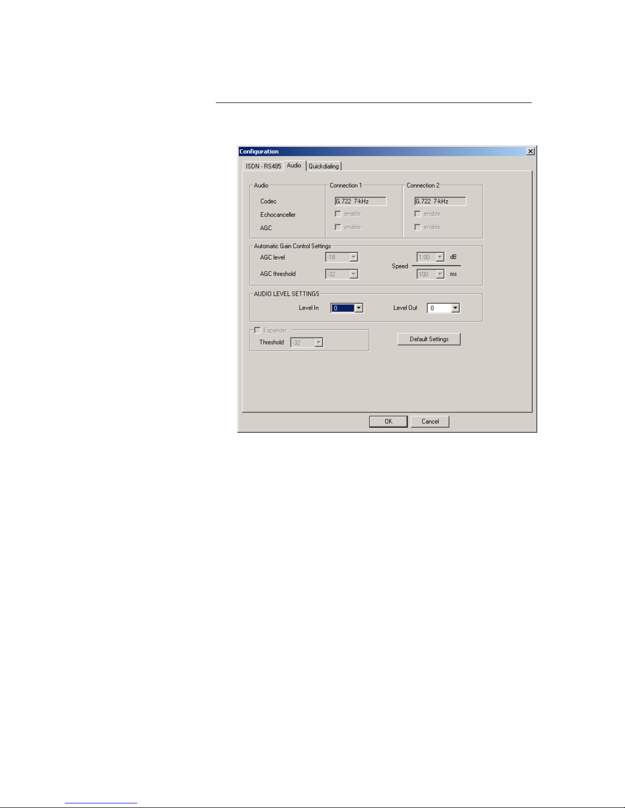
6.4.3.3 Mode 3: Configuration panel for Audio
• In the Audio Field the coding algorithms G.722 7-kHz of Audio codec 1
and Audio codec 2 are displayed. In this Mode Echo Canceller and AGC
can not be enabled.
• In the field Automatic Gain Control Settings also the AGC level, the
AGC threshold and the Speed can not be defined.
• In the AUDIO LEVEL SETTINGS Field the nominal level of the audio sig-
nals can be defined
• In the Field Expander the Threshold value can not be inserted
• If not sure select Default Settings. In this case all levels will be set to op-
erative values
Page 28

PAGE 6-28 RTS ISDN 2002 System
Figure 13: Mode 3: Configuration panel for Audio
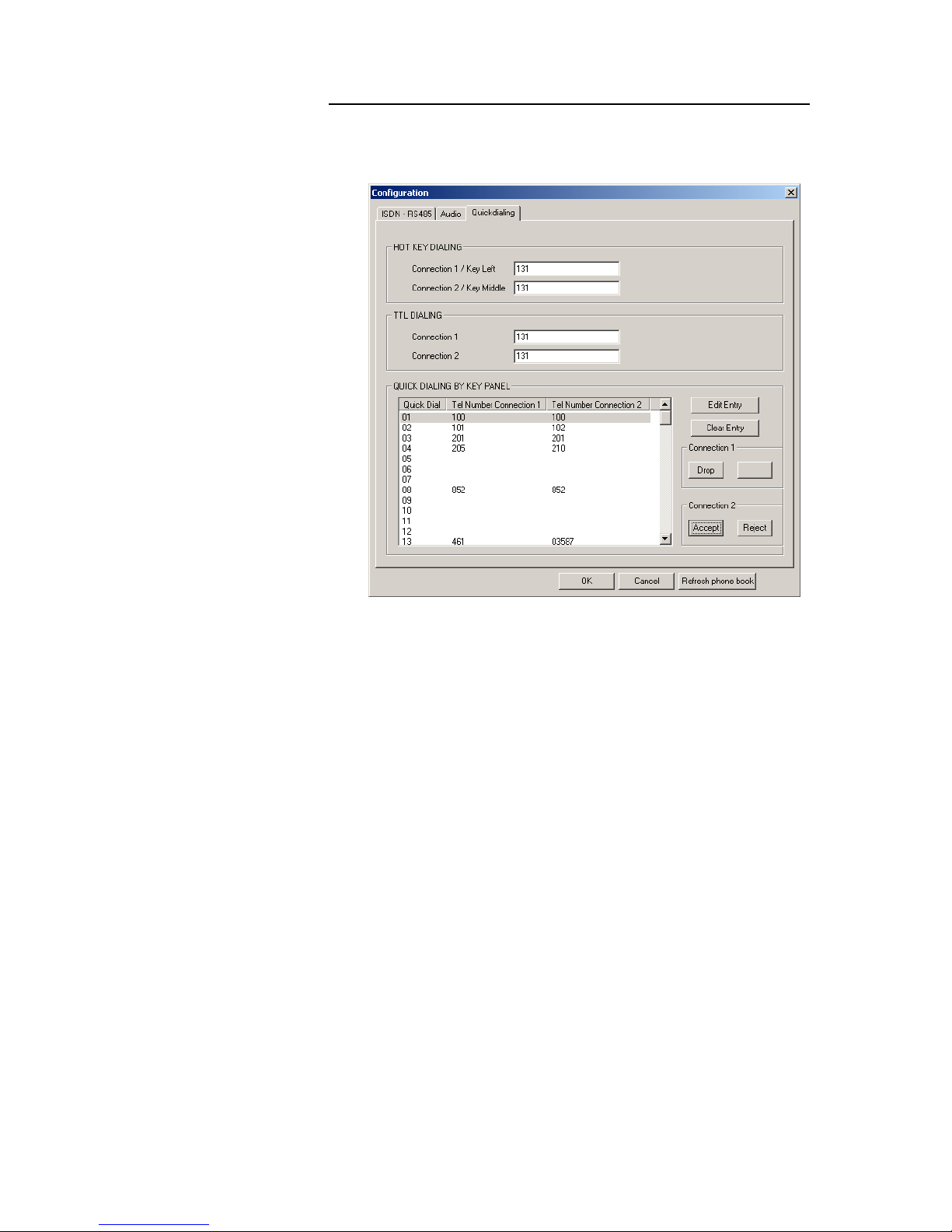
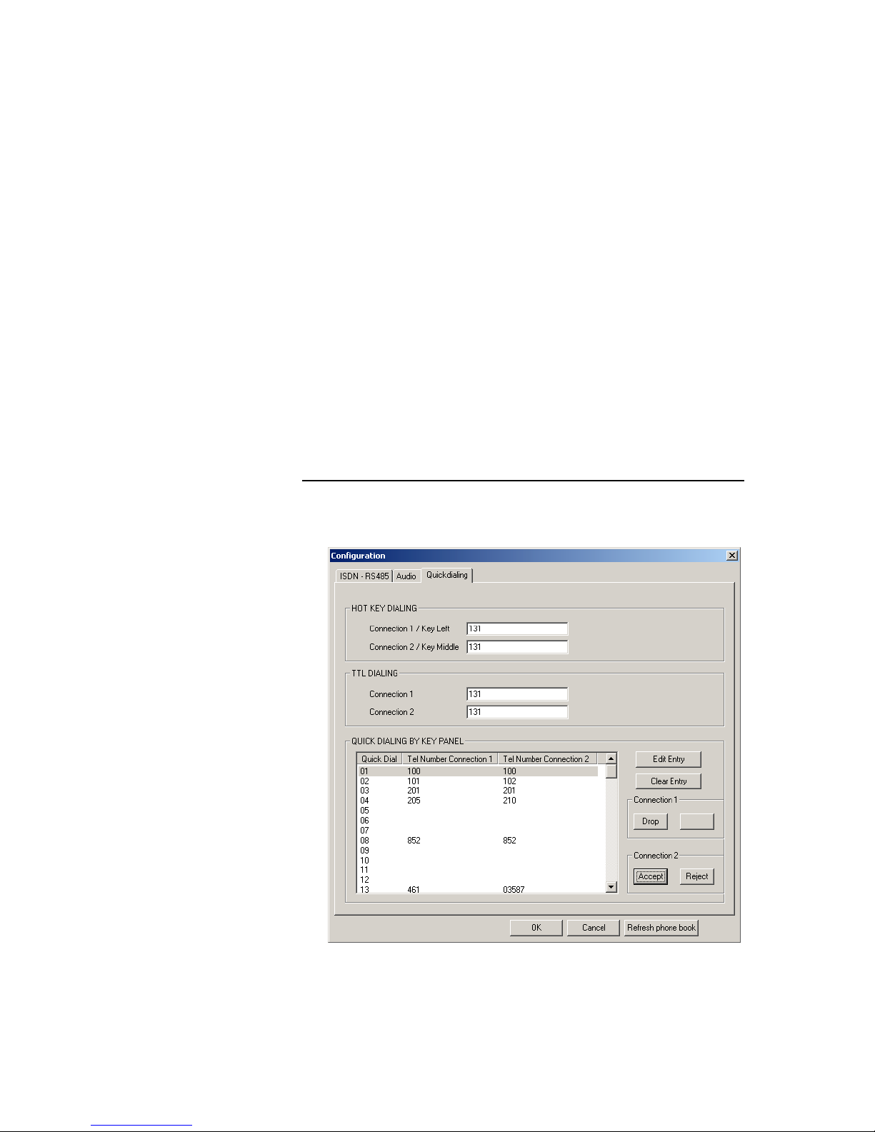
6.4.3.4 Mode 3: Configuration panel for Quick Dialling
• In the HOT KEY DIALLING Field the ISDN telephone numbers for con-
nection 1 for codec 1 and connection 2 for codec 2 can be entered.
Connection 1 can be dialled with the left key on the front and connection 2
can be dialled with the middle key on the front.
• In the field TTL Dialling the ISDN telephone numbers can be adjusted to
the TTL inputs for Audio Codec 1 and 2
• In the QUICK DIALLING BY KEY PANEL Field ISDN telephone numbers
can be inserted and can be adjusted to key Panel Quick Dial Codes and
with the button Refresh the Phone Book can be loaded from the unit. This
function is only available in Mode 1, but can be prepared also in the other
operating modes.
Page 29
RTS ISDN 2002 System PAGE 6-29
Figure 14: Mode 3: Configuration panel for Quick dialling
6.4.4 Operating Mode 4: Matrix to Trunkmaster
In Mode 4 Matrix units are interconnected and audio signals can be routed
controlled by a Trunkmaster unit. For this purpose the data interfaces of the
Matrix units are connected over the RTS ISDN 2002 System to the Trunkmaster system.
6.4.4.1 Mode 4: Main panel
All necessary settings for Audio Codec 1 and Audio Codec 2 are indicated in a
common panel.
• The field PC INTERFACE displays the selected COM port and the status
of the connection (CONNECTED or NOT CONNECTED).
• In the field ISDN the Connection State shows the status of the connection,
in this case the ISDN leased line mode is configured. If there is no connection NO SIGNAL is indicated
• The selection of the BOOK button opens a Telephone Book stored on the
PC
• In the Field AUDIO the coding algorithms of the Audio codecs (G.722, 7-
kHz ) are displayed. In this operating mode AGC and Echo Canceller are
disabled
• Operating mode shows Remote Keypanel for Mode 4
Page 30

PAGE 6-30 RTS ISDN 2002 System
Figure 15: Mode 4: Main panel RTS ISDN 2002 System
Page 31

RTS ISDN 2002 System PAGE 6-31
6.4.4.2 Mode 4: Configuration panel for ISDN and Data
Figure 16: Mode 4: Configuration panel for ISDN and Data
• In the COMMON SETTINGS Field the Operating Mode such as Matrix
Trunkmaster and the Line Mode such as ISDN dial up line or ISDN
leased line can be selected
• In the field ISDN the MSN number for each B channel can be inserted
also the Auto Answer function can be selected with a given answering
time.
• In the RS485 Field the RS 485 address for each Audio channel is not
valid in this operating mode.
• In the Field DATA the interfaces for the data channels can be selected. A
RS232 and a RS485 interface are provided.
6.4.4.3 Mode 4: Configuration panel for Audio
• In the Audio Field the coding algorithms G.722, 7-kHz of Audio codec 1
and Audio codec 2 are displayed. In this Mode Echo Canceller and AGC
can not be enabled.
• In the field Automatic Gain Control Settings also the AGC level, the
AGC threshold and the Speed can not be defined.
• In the AUDIO LEVEL SETTINGS Field the nominal Audio levels can be
defined.
• In the Field Expander the Threshold value can not be inserted
Page 32
PAGE 6-32 RTS ISDN 2002 System
• If not sure select Default Settings. In this case all levels will be set to op-
erative values
Figure 17: Mode 4: Configuration panel for Audio
6.4.4.4 Mode 4: Configuration panel for Quick Dialling
• In the HOT KEY DIALLING Field the ISDN telephone numbers for con-
nection 1 for codec 1 and connection 2 for codec 2 can be entered.
Connection 1 can be dialled with the left key on the front and connection 2
can be dialled with the middle key on the front.
• In the field TTL Dialling the ISDN telephone numbers can be adjusted to
the TTL inputs for Audio Codec 1 and 2
• In the QUICK DIALLING BY KEY PANEL Field ISDN telephone numbers
can be inserted and can be adjusted to key Panel Quick Dial Codes and
with the button Refresh the Phone Book can be loaded from the unit. This
function is only available in Mode 1, but can be prepared also in the other
operating modes.
Page 33
RTS ISDN 2002 System PAGE 6-33
Figure 18: Mode 4: Configuration panel for Quick dialling
6.4.5 Sub menu COM Port
After selection of the sub menu item
COM-Port
a window for the selection
and configuration of the COM interface of the PC opens. If the selected COM
port is already occupied an error message will be displayed. Then select another open COM port. The Baud rate is fixed 19200 Baud.
Figure 19: Sub menu COM-Port
Page 34
PAGE 6-34 RTS ISDN 2002 System
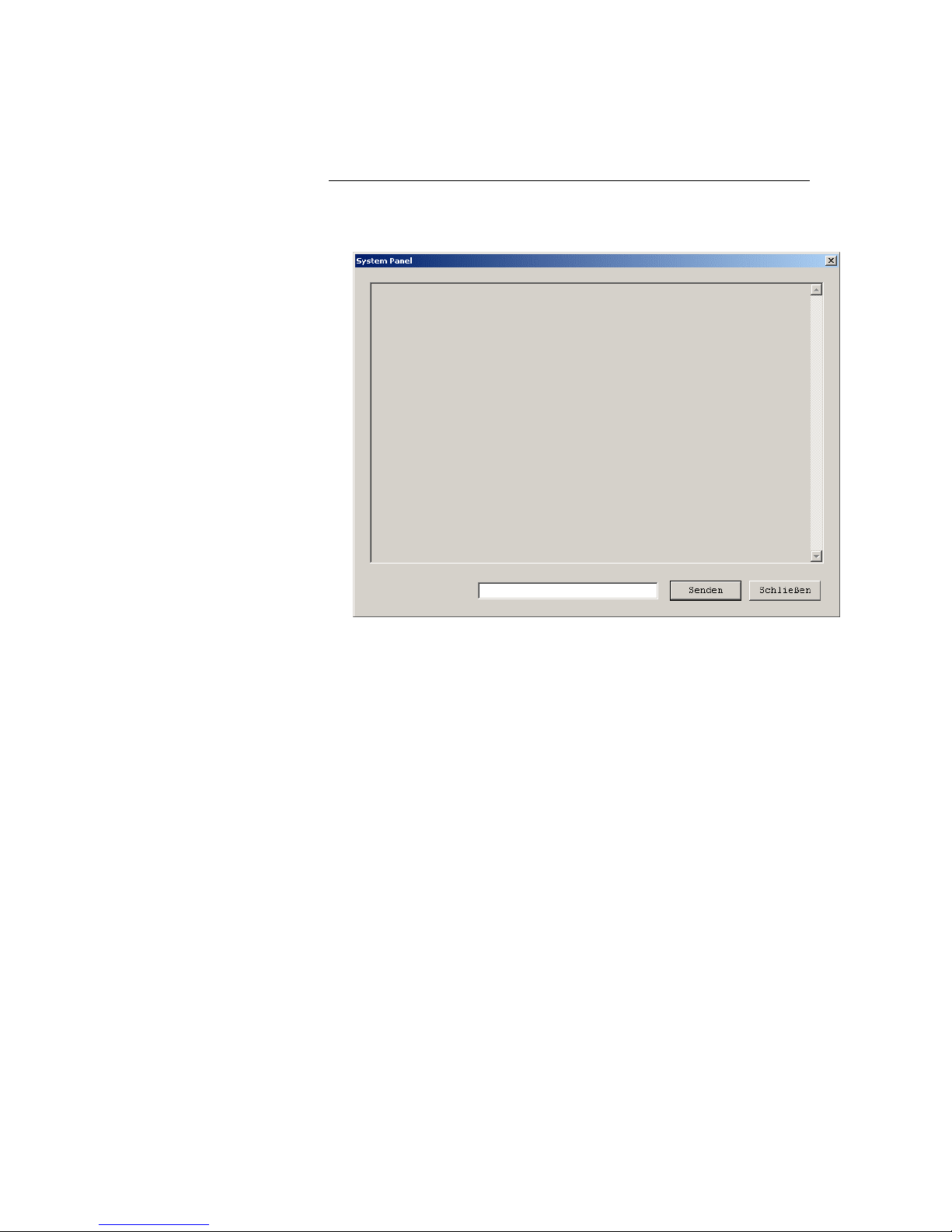
6.4.6 Sub menu System Panel
The sub menu System Panel allows simple communication with RTS ISDN
2002 System. For control purpose string commands can be entered.
Figure 20: Sub menu COM-Port
6.4.7 Sub menu Software Download
The sub menu Software Download is used to copy new software from the PC
to the RTS ISDN 2002 system.
First install the new software on your PC. During the installation also the files
with the new firmware are stored on your PC.
After selection of the sub menu the Software Download window opens.
One of the following software packages will be displayed in accordance to the
stored software:
• IFE_RTS Main software of the system
• So ISDN software
The button "Browse" allows the selection of the drives of the files for the
software download.
Start the transmission of the software to the RTS ISDN 2002 by selecting the
button "Start Download". The button "OK" closes the window.
Page 35

RTS ISDN 2002 System PAGE 6-35
Figure 21: Sub menu Software Download
6.5 Menu Help
Company address and installed software version will be indicated in the menu
help.
Page 36

PAGE 6-36 RTS ISDN 2002 System
Figure 22: Sub menu Help
Page 37

RTS ISDN 2002 System PAGE 7-37
7 DIALLING
The RTS ISDN 2002 System can establish two ISDN connections over its integrated ISDN BRI (So) interface. In the following the dialling interfaces are
described in detail.
7.1 Via PC Software RTS ISDN 2002 Commander
A PC can be connected to the “RS232C” control interface of the RTS ISDN
2002 unit running the RTS ISDN 2002 Commander Software. This software
incorporates a telephone book where the dialling destinations can be chosen.
The telephone book can be selected in the main panel of the software.
• In the field ISDN for each connection a button BOOK for the selection of
the telephone book is available
Figure 23: Mode 1: Main panel RTS ISDN 2002 System
Page 38

PAGE 7-38 RTS ISDN 2002 System
After the BOOK button is selected the telephone book is displayed.
• The telephone book incorporate the name and the associated phone
number
• After selection of an entry the OK button can be selected. In this case the
phonebook will be closed and the selected entry is displayed in the main
panel.
• If the DIAL button will be pressed the selected destination will be dialled
immediately and the phonebook will be closed.
• With the button CANCEL the telephone book can be closed.
• New entries can be inserted after selecting the NEW button
• Existing entries can be modified selecting the EDIT button or can be de-
leted selecting the DELETE button.
• With the IMPORT and EXPORT function telephone books can imported or
the existing telephone book can be stored in a file
Figure 5: Telephone Book for Connection 1 and 2
Page 39
RTS ISDN 2002 System PAGE 7-39
7.2 Via Front keys
The three keys on the front of the RTS ISDN 2002 system can also be used to
dial the two ISDN connections for Audio Codec 1 and Audio Codec 2 and to
drop one or both connections.
TABLE 7.2: Front keys
Front key Function Remarks
Left
Middle
Left/Right
Middle/Right
Dialling of Connection 1
Dialling of Connection 2
Drop of Connection 1
Drop of Connection 2
Left/Right:
Middle/Right:
Both keys must be
pressed together
The telephone numbers for the left and middle key can be adjusted to the
keys by the PC software.
• In the HOT KEY DIALLING Field the ISDN telephone numbers for con-
nection 1 for Audio codec 1 and connection 2 for Audio codec 2 can be
entered.
• Connection 1 can be dialled with the left key on the front
• Connection 2 can be dialled with the middle key on the front.
Figure 25: Mode 1: Configuration panel for Quick dialling
Page 40

PAGE 7-40 RTS ISDN 2002 System
7.3 Via TTL inputs (USER I/O interface)
The USER I/O Interface provides 2 TTL inputs to dial connection 1 and connection 2. The same TTL inputs are used to drop the connections and two
further TTL outputs are providing the status signal of the connection.
TABLE 7.3: TTL Interface (USER I/O)
Pin Function Remarks
3
6
7
8
Connection 1
- call 1 initiation
- disconnect call 1
Connection 2
- call 2 initiation
- disconnect call 2
status call 1
status call 2
Pin 3, 6: falling edge
- call initiation
Pin 3, 6: rising edge
- disconnect
Pin 7, 8: high active
The telephone numbers for connection 1 and connection 2 can be adjusted to
the TTL Pins by the PC software.
• In the TTL DIALING Field the ISDN telephone numbers for connection 1
for Audio codec 1 and connection 2 for Audio codec 2 can be entered.
Figure 26: Mode 1: Configuration panel for Quick dialling
Page 41
RTS ISDN 2002 System PAGE 7-41
7.4 Via Telex Key panel (only Mode 1)
In operating mode 1 of the RTS ISDN 2002 System the connections of Audio
codec 1 and Audio codec 2 can be initiated by key panels which are connected to the same Matrix. With the PC RTS ISDN 2002 Commander software
Telephone numbers can be adjusted to quick dial numbers of the key panels.
Up to 98 entries can be stored.
In the configuration menu of the software the quick dial numbers can be adjusted to the ISDN telephone numbers.
• In the QUICK DIALING BY KEY PANEL Field the ISDN telephone num-
bers for connection 1 for Audio codec 1 and connection 2 for Audio
codec 2 can be entered and adjusted to quick dial numbers of the key
panel
• 98 quick dial positions are displayed
• Empty positions can be filled pressing the Edit Entry button
• Existing entries can be modified selecting the Edit Entry button or can be
deleted selecting the Clear Entry button
• For both connections are two buttons available. The buttons can indicate
Dial, Drop for outgoing calls and Reject, Accept for incoming calls.
Figure 27: Mode 1: Configuration panel for Quick dialling
Page 42

PAGE 8-42 RTS ISDN 2002 System
8 CALL ACCEPTANCE
Incoming calls can be accepted automatically or manually. The following procedures can be used.
8.1 Automatic call acceptance (Auto answer on)
If the auto answer function is selected, incoming calls are automatically accepted.
In the configuration menu of the software the auto answer function can be activated.
• In the ISDN Field the auto answer function can be selected. Also the
ringing time can be defined before the auto answer function shall work.
Figure 28: Mode 1: Configuration panel for ISDN – RS485
8.2 Via Front Keys
An incoming call is indicated by flashing of one of the LEDs DATA CALL 1 or
2 or PHONE CALL 1 or 2 on the front panel.
• If LED DATA CALL 1 or LED PHONE CALL 1 is flashing the call can be
accepted pressing the left key.
• In the case that LED DATA CALL 2 or PHONE CALL 2 is flashing the
call can be accepted with the middle key.
Page 43
RTS ISDN 2002 System PAGE 8-43
8.3 Via PC Software (Connect button)
Incoming calls are indicated in the main panel of the PC software.
• In the field ISDN Connection State an incoming call is indicated by IN-
COMING_CALL.
• Incoming calls can be accepted selecting the Accept button or rejected
selecting the Reject button.
Figure 29: Mode 1: Main Panel
8.4 Via TTL Interface (USER I/O)
Via 2 pins of the User I/O interface the incoming calls can be accepted
TABLE 8.4: TTL Interface (USER I/O)
Pin Function Remarks
3
6
Connection 1
- call 1 acceptance
Connection 2
- call 2 acceptance
Pin 3, 6: falling edge
- call acceptance
8.5 Via Telex Key panel (only mode 1)
In operating mode 1 of the RTS ISDN 2002 system incoming calls are also inserted in the Telex protocol and transmitted to the Telex key panels which are
connected to the same matrix. According to the Telex key panel operation
calls can be accepted with the key panels.
Page 44

PAGE 9-44 RTS ISDN 2002 System
9 INTERFACES
The connectors of the interfaces are at the rear side of the unit.
9.1 Audio interfaces (AUDIO)
RTS ISDN 2002 System incorporate one connector for its Audio interfaces. It
is signed with “AUDIO”. The socket assignment is shown in TABLE 9.1.
TABLE 9.1: AUDIO INPUTS/OUTPUT (AUDIO)
Pin Function Remarks
1
2
3
4
5
6
7
8
9
10
11
12
13
14
15
Codec 2 in a
Codec 2 in b
Codec 1 in a
Codec 1 in b
Codec 2 out a
Codec 2 out b
Codec 1 out a
Codec 1 out b
Ground
Ground
Ground
Ground
Ground
Ground
Ground
Audio level can be set via PC
Software
Figure 30: Rear view of RTS ISDN 2002 System
Page 45

RTS ISDN 2002 System PAGE 9-45
9.2 Control interface (RS232C)
Via the Control interface the whole system can be configured by a PC running
the RTS ISDN 2002 Commander software. The socket assignment of the 9
pin SUB-D connector is shown in TABLE 9.2.
TABLE 9.2: RS 232 Control Interface
Pin Signal Description Characteristic
1
2
3
4
5
6
7
8
9
RXD
TXD
GND
Not used
Receive Data
Transmit Data
Not used
Ground
Not used
Not used
Not used
Not used
Type: DTE
Level: V.24
Data rate: 19200 Baud
Range: max. 15 m
Protocol: 1 start bit
8 data bits
1 stop bit
9.3 RS232 Data Interface (DATA RS232)
In Mode 4 Matrix units are interconnected and audio signals can be routed
controlled by a Trunkmaster unit. For this purpose a RS232 and RS485 data
interfaces are available. The signals of the RS232 interface are described in
TABLE 9.3 .
TABLE 9.3: RS 232 Data Interface
Pin Signal Description Characteristic
1
2
3
4
5
6
7
8
9
RXD
TXD
GND
Not used
Receive Data
Transmit Data
Not used
Ground
Not used
Not used
Not used
Not used
Type: DEE
Level: V.24
Data rate: 9600 Baud
Range: max. 15 m
Protocol: Transparent
1 start bit
8 data bits
1 stop bit
Page 46

PAGE 9-46 RTS ISDN 2002 System
9.4 RS 485 Data Interface (DATA)
The RS485 Data interface can be configured for Mode 1, Mode 2 and Mode 4.
The pin assignment of the connector is shown in TABLE 9.4.
TABLE 9.4: RS485data Interface (SUB-D, 25-pin)
Connect. Signal Description Characteristic
1
2
3
4
5
6
7
8
9
10
11
12
13
14
15
16
17
18
19
20
21
22
23
24
25
GND
Data +
Data -
Not used
Not used
Not used
Not used
Not used
Not used
Not used
Ground
Not used
Not used
Not used
Not used
Not used
Not used
Not used
Data positive
Data negative
Not used
Not used
Not used
Not used
Not used
Not used
Not used
Not used
Data Rate: 9600 Baud
Level: V.11 symmetrical
Protocol:
- RTS protocol (Mode 1)
- Transparent (Mode 2, 4)
1 start bit
8 data bits
1 stop bit
9.5 TTL Interface (USER I/O)
The socket TTL I/O allows the connection of TTL signals and also TTL signals
can be delivered. The pin assignment of the 9 pin SUB-D connector is shown
in TABLE 9.5.
TABLE 9.5: TTL Interface (USER I/O)
Pin Function Remarks
1
2
3
4
5
6
7
8
9
Not used
Ringing call 1
- call 1 acceptance
- call 1 initiation
- disconnect call 1
Ringing call 2
Ground
- call 2 acceptance
- call 2 initiation
- disconnect call 2
status call 1
status call 2
not used
Pin 2, 4: high active
Pin 3, 6: falling edge
- call acceptance
- call initiation
Pin 3, 6: rising edge
- disconnect
Pin 7, 8: high active
Page 47

RTS ISDN 2002 System PAGE 9-47
9.6 ISDN (BRI) Interface (S0 1)
The signals of the ISDN BRI (S0 1) interface are described in
TABLE 9.6.
TABLE 9.6: ISDN BRI Interface: Western socket RJ45 (8-pin)
Pin Signal Description Characteristic
1
2
3
4
5
6
7
8
TXD
RXD
RXD
TXD
Not used
Not used
Transmit Data
Receive Data
Receive Data
Transmit Data
Not used
Not used
Rec.: I.430
Data rate:
- B channels: 2 x 64-kbit/s
- D channel: 16-kbit/s
Page 48

PAGE 10-48 RTS ISDN 2002 System
10 TROUBLE SHOOTING
If the system indicates a fault please make the following checks to get the
system running or allocate the fault .
Fault Possible reason
• After putting the system into operation the 6 LEDs do not light up
for approximately 1 second.
⇒ Please check whether the mains
voltage is missing.
• The system is in operation but
Windows application software can
not recognise the system.
⇒ Is a RS232 control cable used for
the interconnection of PC RTS
ISDN 2002 System (RS232C
connector)?
⇒ Is the right COM-Port of the PC
selected (see chapter 6.4.5)?
• No incoming Audio signal at
Audio interface 1
• No incoming Audio signal at
Audio interface 2
⇒ Is LED "DATA CALL 1” or LED
“PHONE CALL 1” lighting?
⇒ Is LED "DATA CALL 2” or LED
“PHONE CALL 2” lighting?
Page 49

RTS ISDN 2002 System PAGE 11-49
11 CABLING
In this paragraph the cables for the interconnection of the RTS ISDN 2002
System to Matrix unit and Key Panel are described.
11.1 Matrix Connection Cable
The Adam and Zeus matrix units can be delivered with DE-9 or RJ12 connectors.
Figure 31 shows the cable wiring for the interconnection cable for DE-9 connectors on the matrix and Figure 32 the wiring for RJ12 connectors on the
matrix.
Figure 31: DE-9 intercom cable Matrix
Page 50
PAGE 11-50 RTS ISDN 2002 System
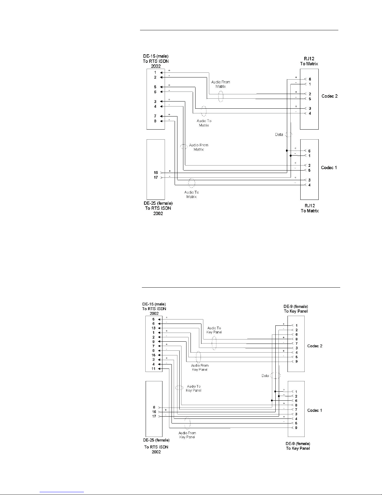
11.2 Key Panel Connection Cable
The Key Panels incorporate DE-9 and RJ12 interfaces for the connection to
RTS ISDN 2002 System. Figures 33 and 34 show the cable wiring for the interconnection cables for DE-9 and RJ12 interfaces on the Key Panel.
Figure 32: RJ12 intercom cable Matrix
Figure 33: DE-9 intercom cable Key Panel
Page 51

RTS ISDN 2002 System PAGE 11-51
Figure 34: RJ12 intercom cable Key Panel
 Loading...