

Page 1
IFB-828 IFB Interface User Manual
9300709400 Rev H 04/2010
Page 2
PROPRIETARY NOTICE
SHIPPING TO THE MANUFACTURER
The product information and design disclosed herein were originated by and are the property of Bosch Security Systems, Inc.
Bosch reserves all patent, proprietary design, manufacturing, reproduction, use and sales rights thereto, and to any article disclosed
therein, except to the extent rights are expressly granted to others.
COPYRIGHT NOTICE
Copyright 2010 by Bosch Security Systems, Inc. All rights
reserved. Reproduction, in whole or in part, without prior written
permission from Bosch is prohibited.
WARRANTY NOTICE
See the enclosed warranty card for further details.
CUSTOMER SUPPORT
Te chnical questions should be directed to:
Customer Service Department
Bosch Security Systems, Inc.
12000 Portland Avenue South
Burnsville, MN 55337 USA
Telephone: 877-863-4169
Fax: 800-323-0498
RETURN SHIPPING INSTRUCTIONS
Customer Service Department
Bosch Security Systems, Inc. (Lincoln, NE)
Telephone: 402-467-5321
Fax: 402-467-3279
Factory Service: 800-553-5992
Please include a note in the box which supplies the company name,
address, phone number, a person to contact regarding the repair , the
type and quantity of equipment, a description of the problem and
the serial number(s).
All shipments of product should be made via UPS Ground, prepaid
(you may request from Factory Service a different shipment
method). Any shipment upgrades will be paid by the customer. The
equipment should be shipped in the original packing carton. If the
original carton is not available, use any suitable container that is
rigid and of adequate size. If a substitute container is used, the
equipment should be wrapped in paper and surrounded with at least
four (4) inches of excelsior or similar shock-absorbing material. All
shipments must be sent to the following address and must include
the Proof of Purchase for warranty repair . Upon completion of any
repair the equipment will be returned via United Parcel Service or
specified shipper, collect.
Factory Service Department
Bosch Security Systems, Inc.
8601 East Cornhusker Hwy.
Lincoln, NE 68507 U.S.A.
Attn: Service
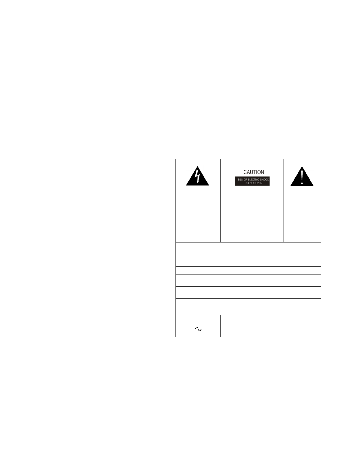
THE LIGHTNING
FLASH AND
ARROWHEAD
WITHIN THE TRIANGLE IS A WARNING
SIGN ALERTING
YOU OF “DANGEROUS VOLTAGE”
INSIDE THE PRODUCT.
SEE MARKING ON BOTTOM/BACK OF PRODUCT
WARNING: APPARATUS SHALL NOT BE EXPOSED TO DRIPPING OR
SPLASHING AND NO OBJECTS FILLED WITH LIQUIDS, SUCH AS VASES,
SHALL BE PLACED ON THE APPARATUS.
WARNING: THE MAIN POWER PLUG MUST REMAIN READILY OPERABLE.
CAUTION: TO REDUCE THE RISK OF ELECTRIC SHOCK, GROUNDING OF
THE CENTER PIN OF THIS PLUG MUST BE MAINTAINED.
WARNING: TO REDUCE THE RISK OF FIRE OR ELECTRIC SHOCK, DO NOT
EXPOSE THIS APPRATUS TO RAIN OR MOISTURE.
WARNING: TO PREVENT INJURY, THIS APPARATUS MUST BE SECURELY
ATTACHED TO THE FLOOR/WALL/RACK IN ACCORDANCE WITH THE
INSTALLATION INSTRUCTIONS.
CAUTION: TO REDUCE THE
RISK OF ELECTRIC SHOCK,
DO NOT REMOVE COVER. NO
USER-SERVICABLE PARTS
INSIDE. REFER SERVICING T O
QUALIFIED SERVICE PERSONNEL.
THE EXCLAMATION POINT
WITHIN THE
TRIANGLE IS A
W ARNING SI GN
ALERTING YOU
OF IMPORTANT
INSTRUCTIONS
ACCOMPANYING THE PRODUCT
This product is AC only.
Page 3

Important Safety Instructions
1. Read these instructions.
2. Keep these instructions.
3. Heed all warnings.
4. Follow all instructions.
5. Do not use this apparatus near water.
6. Clean only with dry cloth.
7. Do not block any ventilation openings. Install in accordance with the
manufacturer’s instructions.
8. Do not install near any heat sources such as radiators, heat registers, stoves,
or other apparatus (including amplifiers) that produce heat.
9. Do not defeat the safety purpose of the polarized or grounding-type plug. A
polarized plug has two blades with one wider than the other. A grounding
type plug has two blades and a third grounding prong. The wide blade or the
third prong are provided for your safety . If the provided plug does not fit into
your outlet, consult an electrician for replacement of the obsolete outlet.
10. Protect the power cord from being walked on or pinched particularly at
plugs, convenience receptacles, and the point where they exit from the
apparatus.
11. Only use attachments/accessories specified by the manufacturer.
12. Use only with the cart, stand, tripod, bracket, or table specified by the
manufacturer, or sold with the apparatus. When a cart is used, use caution
when moving the cart/apparatus combination to avoid injury from tip-over.
13. Unplug this apparatus during lightning storms or when unused for long
periods of time.
14. Refer all servicing to qualified service personnel. Servicing is required when
the apparatus has been damaged in any way, such as power-supply cord or
plug is damaged, liquid has been spilled or objects have fallen into the
apparatus, the apparatus has been exposed to rain or moisture, does not
operate normally, or has been dropped.
Page 4

Page 5

Table
of
Contents
DESCRIPTION AND SPECIFICATIONS .................................................................................................3
Description ................................................................................................................................................................3
Specifications .............................................................................................................................................................4
INSTALLATION .......................................................................................................................................... 5
Installation in an RTS Digital Matrix ........................................................................................................................5
IFB-828 LOCATION ..................................................................................................................................................................5
M
ONAURAL EARSET PIN OUT ....................................................................................................................................................6
TEREO EARSET PIN OUT .........................................................................................................................................................6
S
Using the IFB-828 as a Simple Program Interface with 4020 and 4030 Belt Packs ................................................7
Page 6

Page 7

CHAPTER 1
Description and Specifications
Description
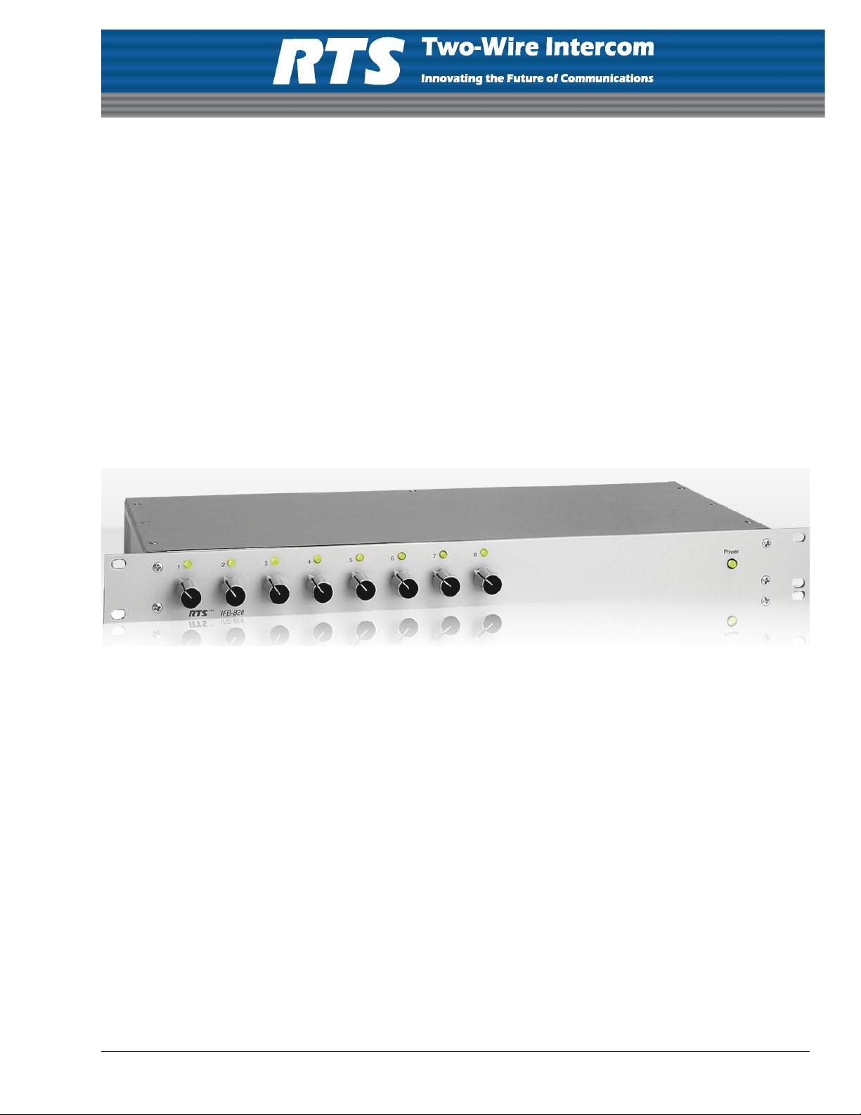
The IFB-828 interfaces up to eight (8) RTS System’ s Model IFB-325, 4020, or 4030 IFB Belt Packs to any RTS Digital Matrix
Intercom System, and it provides power to belt packs.
The IFB-828 may also be used as a simple program interface to feed two (2) separate program sources to each of eight (8)
4020 or 4030 belt packs (16 program sources to eight (8) belt packs total).
FIGURE 1. IFB-828 Reference View
3
Page 8

Description and Specifications
Specifications
Dimensions
19” wide x 1.75” high x 7.5” deep (483mm x 44.5mm x 191mm)
Input Power Requirements
110/120 or 220/240 VAC, 50/60Hz, selectable via a back panel switch
Audio Inputs
Type:
Balanced (transformer coupled)
Level:
+4 to +8dBu
Impedance
Approximately 600 Ohms
Audio Outputs
Type
Unbalanced
Level:
-10 to -6dBu
Output Power (each IFB belt pack channel)
+24VDC, 160mA not to exceed a total of 750mA
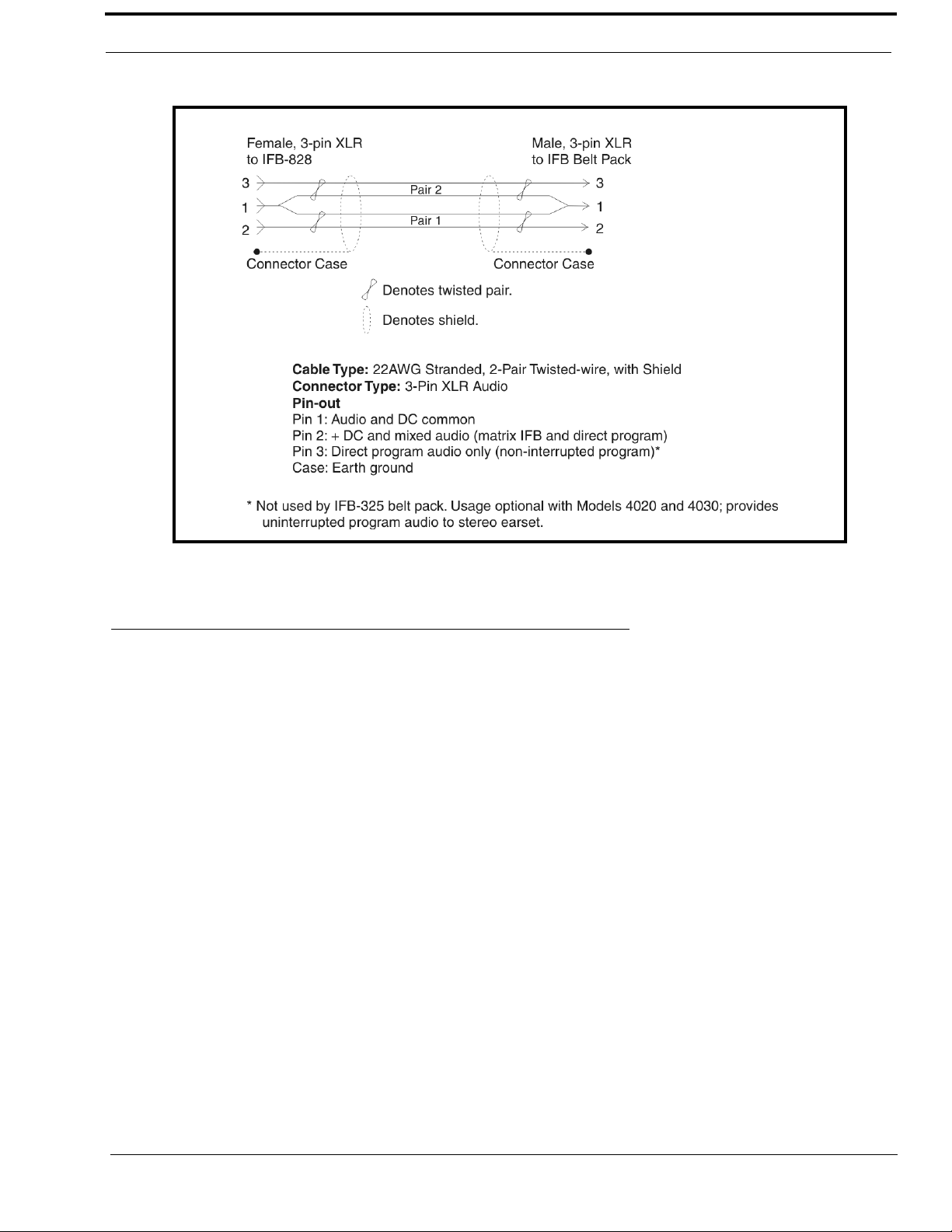
Connectors
Input (J9)
T ype: 50-pin telco
Outputs (J1 to J8)
Type: 3-Pin Male XLR
Pin 1 Audio and DC Common
Pin 2 +IFB Audio (interrupt audio) and +24VDC
Pin 3 +Direct Program Audio (non-interrupt audio)
4
Page 9

CHAPTER 2
Installation
Installation in an RTS Digital Matrix
IFB-828 Location
The XLR connector output from the IFB-828 provides unbalanced audio and DC operating power to IFB belt packs.
Therefore, very long cable runs (over several hundred feet) from the IFB-828 to the belt packs may result in diminished
performance due to DC resistance in the cabling and noise induced by surrounding equipment. Select a location for the
IFB-828 that is as close as possible to the belt packs or use appropriate precautions (shielded cable, heavier gauge stranded
wire, routing away from unsaddled equipment, etc.)
NOTE: For broadcast applications, you typically locate the IFB-828 in the audio booth near the talent location, and no
special precautions are required.
To install an IFB-828 in an RTS Digital Matrix, do the following:
1. Mount the IFB-828 in an equipment rack or bay. It should be positioned near eye height when sitting or standing to
permit adjustment of the IFB program levels and to check the power indicator lights. There are no special ventilation
requirements.
2. Set the voltage selector switch on the back panel:
• Select 110 for 110/120V, 50/60Hz operation
• Select 220 for 220/240V, 50/60Hz operation
3. Connect a 25-pair telco cable to J9 on the back of the IFB-828. Run this cable back to the audio distribution point for
the intercom system (punch blocks, etc.).
4. Setup IFBs at the digital matrix intercom system using the intercom system configuration software.
5. In AZedit, select the IFB icon on the AZedit toolbar.
6. Double-click an IFB resource.
The Edit IFB window appears.
7. Configure the IFB ports, as needed.
8. Once you have configured the required IFBs, assign the IFBs to keypanel keys.
NOTE: For keypanel setup information, see the AZedit User Manual (p/n 93507769000).
9. For each IFB that you setup, do the following:
• Connect the output port from the matrix (that you defined in step 4) to an available IFB input of the IFB-828.
Make the connections at the audio distribution point where you have connected the cable from J9 of the IFB-828.
See Table 1 on page 6 for pin numbers.
5
Page 10

Installation
• Connect the IFB program audio source to the
intercom port that you defined as the program
input port of the matrix (in step 4) and connect
the IFB program audio source to the direct
program input of the selected channel of the
IFB-828.
10. Connect the appropriate 3-pin XLR output
connector of the IFB-828 to the LINE (or LINES)
connector of the IFB belt pack. Typical cable
wiring is shown in Figure 2.
NOTE: In the factory default configuration, the
IFB-325 belt packs receive IFB audio on
pin 3 of its XLR connector. In this
configuration, the belt pack’s internal
shorting plug J3 is set to pins 2 and 3
shorted. This is NOT the correct
configuration for use with the IFB-828. To
change the setting open the belt pack and
reset the H3 shorting plug so that pins 4
and 5 are shorted. Refer to your IFB-325
manual for further information.
11. Connect an earset to the IFB belt pack.
NOTE: The Model IFB-325 accepts only
monaural earsets. The Models 4020 and
4030 accept either monaural or stereo
earsets. However, for the standard
application of the IFB-828, only a
monaural earset is required.
12. Set all belt pack volume controls and all level
controls on the IFB-828 to minimum.
13. Plug in the IFB-828 power cord.
The main power LED on the front panel should
light, and each channel LED lights indicating
power is being supplied to the belt pack output on
that channel. Verify the matrix is operational and
that all program sources are operational.
14. During normal operation (no IFB interrupts
activated), have each talent position adjust their
belt pack volume control for a comfortable
program listening level. (Use the INTERRUPT
control on a model 4020 or 4030 belt pack.)
15. For each IFB:
• Activate the keypanel key assigned to the IFB.
The program audio should be interrupted at the
associated IFB belt pack, and the mic audio
from the keypanel should become audible.
• While the IFB key is activated, adjust the
appropriate level control on the front panel of
the IFB-828 to mix the desired amount of
direct program audio back into the keypanel’s
mic audio signal.
When the IFB key is released, the mic audio
should cut off, and the normal program audio
should be restored.
Monaural Earset Pin Out
Tip: IFB Audio & Direct Program Mix
Sleeve: Common
Stereo Earset Pin Out
Tip: IFB Audio & Direct Program Mix (Interrupt)
Ring: Direct Program Audio (Non-Interrupt
Sleeve: Common
TABLE 1. Input Connector Pin Out (J9)
Pin Numbers
Description
+ Input - Input
1 26 Channel 1 direct program input
2 27 Channel 1 IFB input (from Matrix)
3 28 No Connection
4 29 Channel 2 direct program input
5 30 Channel 2 IFB input (from Matrix)
6 31 No Connection
7 32 Channel 3 direct program input
8 33 Channel 3 IFB input (from Matrix)
9 34 No Connection
10 35 Channel 4 direct program input
11 36 Channel 4 IFB input (from Matrix)
12 37 No Connection
13 38 Channel 5 direct program input
14 39 Channel 5 IFB input (from Matrix)
15 40 No Connection
16 41 Channel 6 direct program input
17 42 Channel 6 IFB input (from Matrix)
18 43 No Connection
19 44 Channel 7 direct program input
20 45 Channel 7 IFB input (from Matrix)
21 46 No Connection
22 47 Channel 8 direct program input
23 48 Channel 8 IFB input (from Matrix)
24 49 No Connection
25 50 No Connection
6
Page 11
Installation
FIGURE 2. IFB Belt Pack Interconnect Cable Wiring Diagram
Using the IFB-828 as a Simple Pr ogram Interface with 4020 and 4030 Belt Packs
Use Table 1 on page 6 and the cable wiring sources to each IFB-828 channel. In this application, each direct program input at
the IFB-828 feeds to the NON-INTERRUPT channel of the belt pack, and the level is adjusted by the NON-INTERRUPT
control on the belt pack; each IFB input feeds to the INTERRUPT channel and is adjusted by the INTERRUPT control. The
control on the IFB-828 front panel can be used to mix the NON-INTERRUPT audio into the INTERRUPT audio.
7
Page 12

 Loading...