

Page 1
OPERATING INSTRUCTIONS
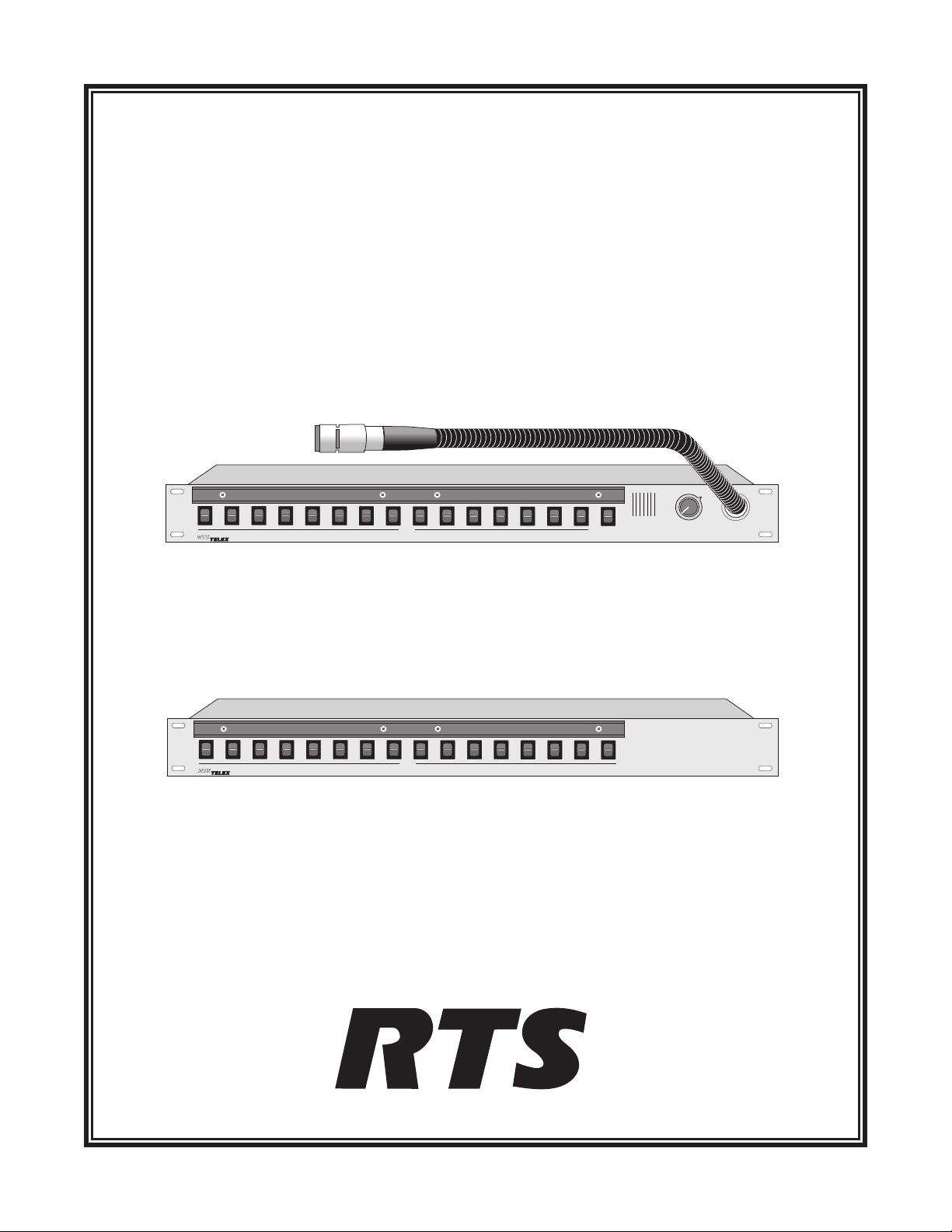
KP95-0 KEYPANEL
VERSION 8.2
WITH EKPD-95 EXPANSION PANEL
™
ADAM
, ADAM™CS, AND ZEUS™INTERCOM SYSTEMS
Incoming Messages
Programing
Clear
Call
Answer
Off
Talk
Off
(Talk)
BY
Matrix Intercom System
Talk
KP95-0 Keypanel
Talk
Off
(Talk)
BY
Matrix Intercom System
Talk
EKPD-95 Expansion Panel
9350-7101-004V8.2RevB8/00
™
Page 2

PROPRIETARY NOTICE
CUSTOMER SUPPORT
The RTS product information and design disclosed herein were
originated by and are the property of Telex Communications,
Inc. Telex reserves all patent, proprietary design, manufacturing, reproduction, use and sales rights thereto, and to any article
disclosed therein, except to the extent rights are expressly
granted to others.
COPYRIGHT NOTICE
Copyright 1997 by Telex Communications, Inc. All rights reserved. Reproduction in whole or in part without prior written
permission from Telex is prohibited.
UNPACKING AND INSPECTION
Immediately upon receipt of the equipment, inspect the shipping container and the contents carefully for any discrepancies
or damage. Should there be any, notify the freight company and
the dealer at once.
WARRANTY INFORMATION
RTS products are warrantedbyTelex Communications, Inc. to
be free from defects in materials and workmanship for a period
of three years from the date of sale.
The sole obligation of Telex during the warranty period is to
provide, without charge, parts and labor necessary to remedy
covered defects appearing in products returned prepaid to
Telex. This warranty does not cover any defect, malfunction or
failure caused beyond the control of Telex, including unreasonable or negligent operation, abuse, accident, failure to follow
instructions in the Service Manual or the User Manual, defective or improper associated equipment, attempts at modification
and repair not authorized by Telex, and shipping damage. Products with their serial numbers removed or effaced are not covered by this warranty.
To obtain warranty service, follow the procedures entitled "Procedure For Returns" and "Shipping to Manufacturer for Repair
or Adjustment".
This warranty is the sole and exclusive express warranty given
with respect to RTS products. It is the responsibility of the user
to determine before purchase that this product is suitable for the
user's intended purpose.
ANY AND ALL IMPLIED WARRANTIES, INCLUDING
THE IMPLIED WARRANTY OF MERCHANTABILITY
ARE LIMITED TO THE DURATION OF THIS EXPRESS
LIMITED WARRANTY.
NEITHER TELEX NOR THE DEALER WHO SELLS RTS
PRODUCTS IS LIABLE FOR INCIDENTAL OR CONSEQUENTIAL DAMAGES OF ANY KIND.
Technicalquestionsshouldbedirectedto:
Customer Service Department
RTS/Telex,
12000 Portland Avenue South
Burnsville, MN 55337 U.S.A.
Telephone:(952)884-4051
Fax:(800)323-0498
RETURN SHIPPING INSTRUCTIONS
PROCEDURE FOR RETURNS
If a repair is necessary, contact the dealer where this unit was
purchased.
If repair through the dealer is not possible, obtain a RETURN
AUTHORIZATION from:
Customer Service Department
Telex Communications, Inc.
Telephone:(877)863-4169
Fax: (800) 323-0498
DO NOT RETURN ANY EQUIPMENT DIRECTLY TO
THE FACTORY WITHOUT FIRST OBTAINING A
RETURN AUTHORIZATION.
Be prepared to provide the company name, address, phone
number, a person to contact regarding the repair, the type and
quantity of equipment, a description of the problem and the serial number(s).
SHIPPING TO MANUFACTURER FOR REPAIR OR
ADJUSTMENT
All shipments of RTS products should be made via United Parcel Service or the best available shipper, prepaid. The equipment should be shipped in the original packing carton; if that is
not available, use any suitable container that is rigid and of adequate size. If a substitute container is used, the equipment
should be wrapped in paper and surrounded with at least four
inches of excelsior or similar shock-absorbing material. All
shipments must be sent to the following address and must include the Return Authorization.
Factory Service Department
Telex Communications, Incorporated
8601 E. Cornhusker Hwy
Lincoln, NE 68505 U.S.A.
Upon completion of any repair the equipment will be returned
via United Parcel Service or specified shipper collect.
2KP95-0 Keypanel Operation Manual, Ver. 8.2
Page 3

Table of Contents
INTRODUCTION ················································4
DESCRIPTION OF USER CONTROLS AND FEATURES ··························4
KEYPANEL OPERATION ···········································5
POWER SWITCH ··············································5
VOLUME ADJUSTMENT··········································5
PLACING A CALL··············································5
RECEIVING CALLS FROM OTHER KEYPANELS ····························5
List of Figures
KP95-0 Keypanel·················································1
EKPD-95 Expansion Panel············································1
Figure 1: Keypanel Reference View.·······································4
KP95-0 Keypanel Operation Manual, Ver. 8.2 3
Page 4

1 INTRODUCTION
This manual describes the operating procedures for the KP95-0 keypanel when used in an ADAM™, ADAM CS
or Zeus™ DSP Intercom System. The KP95-0 must be programmed from a PC with the ADAMedit or ZEUSedit
intercom configuration software. If you need to change the keypanel setup or access other information about the
keypanel setup, you will need to consult with your system administrator.
1
Talk
Off
(Talk)
BY
2
Matrix Intercom System
1. Designation Strip Holder
2.Talk Keys
3
Talk
Incoming Messages
Programing
4. Incoming Messages Key
5. Intercom Volume
3. Gooseneck Microphone
Figure 1: Keypanel Reference View.
2 DESCRIPTION OF USER CONTROLS AND FEATURES
(See Figure 1 for numbered call-outs)
4
Clear
Off
Call
Answer
5
1. Designation Strip Holder: A strip can be inserted here to identify the talk key assignments. Designation strips
show the alphanumeric names for the destinations (intercom ports, party lines, etc.) that have been assigned to
the talk keys. The ADAMedit or ZEUSedit intercom configuration software is used to assign these names and
print the designation strips. See “Alpha Assignments” and “Print” in the application help.
2. Talk Keys: These are used to talk to the keypanels, party lines, etc. that are indicated on the designation strip.
3. Gooseneck Microphone: Pressing any talk key activates the gooseneck microphone.
4. Incoming Messages Key: When a call is received, pressing the incoming messages key will allow you to
respond to the caller.
5. Intercom Volume: The outer volume control knob adjusts headphone and speaker volume for intercom
communications.
4 KP95-0 Keypanel Operation Manual, Ver. 8.2
Page 5

3 KEYPANEL OPERATION
3.1 POWER SWITCH
A power switch is located on the back of each keypanel and expansion panel next to the power cord connector.
3.2 VOLUME ADJUSTMENT
Adjust your speaker listen level as desired (or headphone listen level if you are using an optional headset).
If listen levels for one or more key assignments are higher or lower than the rest, ask your system administra-
+
tor to adjust these levels at the intercom system.
3.3 PLACING A CALL
Activate the talk key for the person, party line etc. that you want to talk to:
For momentary talk, hold down the talk key and talk into the microphone. When you
release the key, it will return to the center (off) position.
For hands-free talk, place the talk key in the “up” position and talk into the microphone.
Return the talk key to the center (off) position when finished with your conversation.
You may not be able to hear the person, party line, etc. to whom you are talking. This can happen when talk-
+
ing to non-keypanel devices. In this case, ask your system administrator to change the listen assignment for
that key. For example, the key can be assigned with auto-listen so that listen automatically activates whenever
the talk key is pressed.
On some occasions, when a particular talk key is pressed, the call will not be placed. There are two occasions
+
when this happens. The first is when the key is assigned to an IFB and another keypanel with a higher IFB
priority is currently using the IFB. The second occasion applies in ADAM or ADAM CS intercom systems
when the talk key is assigned to a person, party line, etc. of a remote intercom system, and there are currently
no trunk lines available to route the call.
3.4 RECEIVING CALLS FROM OTHER KEYPANELS
Whenever there is an incoming call, you will hear the caller in your speaker or headset. If there is a talk key
assigned to the caller, you can respond by pressing it. However, since the KP95-0 does not have displays for
incoming caller identification, the standard procedure is to use the talk keys for outgoing calls only and to use the
Incoming Messages key to respond to incoming calls. Simply press the Incoming Messages key to talk back. If
another person calls you during your conversation with the first caller, you will also hear the new caller. To talk to
the new caller, you must first clear the previous caller by momentarily placing the Incoming Messages key in the
Clear (up) position. Then press down to talk to the new caller.
KP95-0 Keypanel Operation Manual, Ver. 8.2 5
Page 6

Notes
6 KP95-0 Keypanel Operation Manual, Ver. 8.2
Page 7

Page 8

™
 Loading...