

RTS KP-98-7, EKP98-0, LCP-100A Installation Instructions Manual
INSTALLATION INSTRUCTIONS
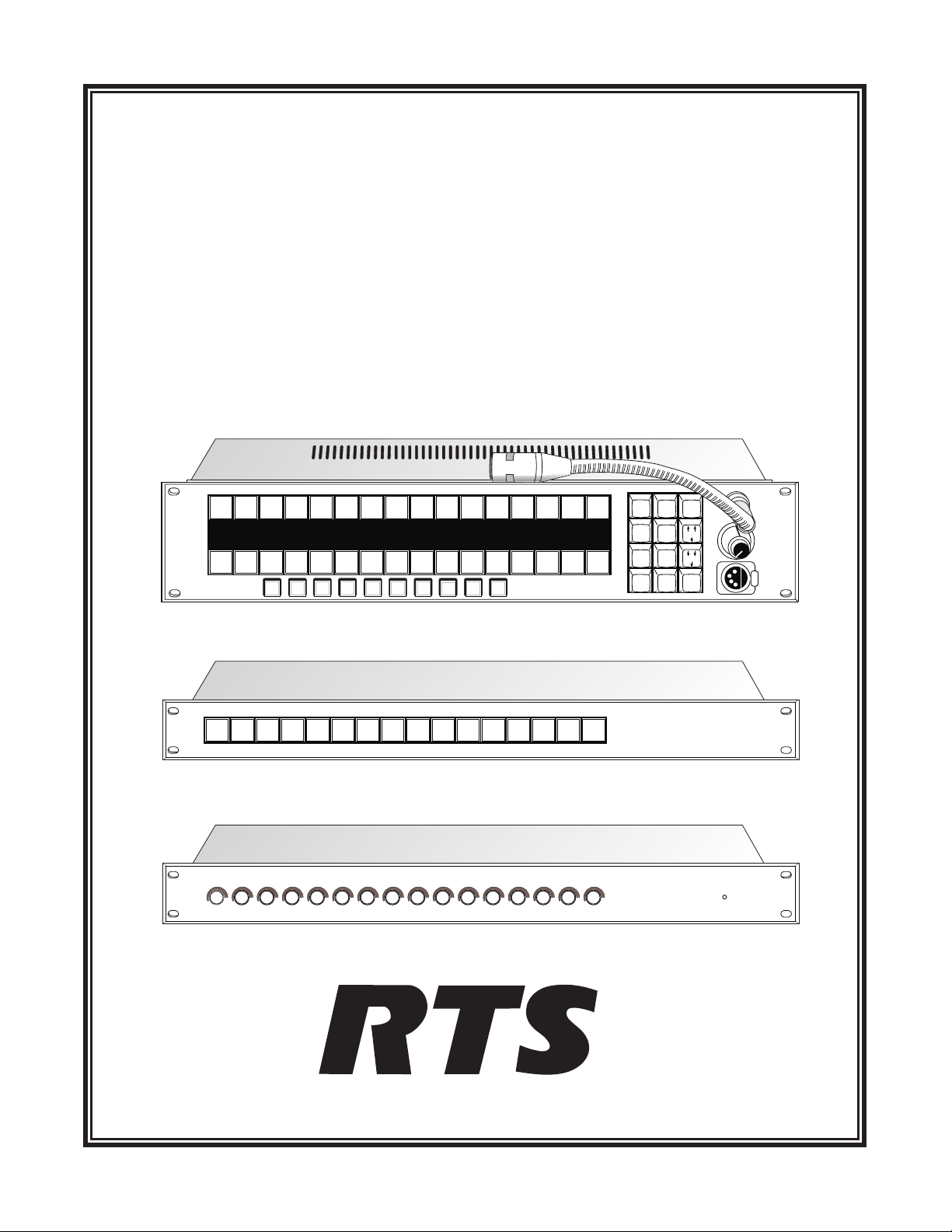
KP98-7 KEYPANEL
VERSION 8.2
WITH EKP98-0 EXPANSION PANEL AND LCP-100A LEVEL CONTROL PANEL
ADAM™, ADAM™ CS, AND ZEUS™ INTERCOM SYSTEMS
NUM
PL
PREFIX
TYPE
E-PNL
DISPLAY
MULT
FUNC
AUTO
3
2
IFB
ISO
5
6
8
9
PGM
0
PUSH
VOLUME
HEADSET
LISTEN1LISTEN2LISTEN3LISTEN4LISTEN5LISTEN6LISTEN7LISTEN8LISTEN9LISTEN10LISTEN11LISTEN12LISTEN13LISTEN14LISTEN
DIR
PROD RACK
TALK
1
KP98-7
TALK2TALK
PL01
3
Page1Page
IFB4
TALK
4
2
TD
NEWS
AD
TALK5TALK6TALK
Page
Page
3
4
7
Level
SAT1
TEL1 TEL2 FLOR
TALK
TALK
8
Phone
TALK10TALK
9
PL
IFB
Scroll
Scroll
CHYR
IS01 IS02
TALK
TALK13TALK14TALK
12
11
Mic
Headset
Enable
KP98-7
CALL
15
CLEAR
AUD1
15
ANSWER
1
SLIST
PHONE
4
RELAY
COPY CW
7
CALL
EX COPY
CLR
TALK2TALK
TALK
1
3
TALK
4
TALK5TALK6TALK
9330-7410-000 V8.2 Rev A2,12/98
TALK
TALK
7
TALK10TALK
9
8
TALK
TALK13TALK14TALK TALK
12
11
15 16
KP98-7
EKP98-0
LCP-100A
LCP-100A
™

PROPRIETARY NOTICE
CUSTOMER SUPPORT
The RTS product information and design disclosed herein were
originated by and are the property of Telex Communications, Inc.
Telex reserves all patent, proprietary design, manufacturing, reproduction, use and sales rights thereto, and to any article disclosed
therein, except to the extent rights are expressly granted to others.
COPYRIGHT NOTICE
Copyright 1997 by Telex Communications, Inc. All rights reserved. Reproduction in whole or in part without prior written permission from Telex is prohibited.
UNPACKING AND INSPECTION
Immediately upon receipt of the equipment, inspect the shipping
container and the contents carefully for any discrepancies or damage. Should there be any, notify the freight company and the dealer
at once.
WARRANTY INFORMATION
RTS products are warranted by Telex Communications, Inc. to be
free from defects in materials and workmanship for a period of
three years from the date of sale.
The sole obligation of Telex during the warranty period is to provide, without charge, parts and labor necessary to remedy covered
defects appearing in products returned prepaid to Telex. This warranty does not cover any defect, malfunction or failure caused beyond the control of Telex, including unreasonable or negligent
operation, abuse, accident, failure to follow instructions in the
Service Manual or the User Manual, defective or improper associated equipment, attempts at modification and repair not authorized
by Telex, and shipping damage. Products with their serial numbers
removed or effaced are not covered by this warranty.
To obtain warranty service, follow the procedures entitled "Procedure For Returns" and "Shipping to Manufacturer for Repair or
Adjustment".
This warranty is the sole and exclusive express warranty given with
respect to RTS products. It is the responsibility of the user to determine before purchase that this product is suitable for the user's intended purpose.
ANY AND ALL IMPLIED WARRANTIES, INCLUDING
THE IMPLIED WARRANTY OF MERCHANTABILITY
ARE LIMITED TO THE DURATION OF THIS EXPRESS
LIMITED WARRANTY.
NEITHER TELEX NOR THE DEALER WHO SELLS RTS
PRODUCTS IS LIABLE FOR INCIDENTAL OR CONSEQUENTIAL DAMAGES OF ANY KIND.
Technical questions should be directed to:
Customer Service Department
RTS/Telex,
2550 Hollywood Way, Suite 207
Burbank, CA 91505 U.S.A.
Telephone: (818) 566-6700
Fax: (818) 843-7953
RETURN SHIPPING INSTRUCTIONS
PROCEDURE FOR RETURNS
If a repair is necessary, contact the dealer where this unit was purchased.
If repair through the dealer is not possible, obtain a RETURN
AUTHORIZATION from:
Customer Service Department
Telex Communications, Inc.
Telephone: (800) 828-6107
Fax: (800) 323-0498
DO NOT RETURN ANY EQUIPMENT DIRECTLY TO THE
FACTORY WITHOUT FIRSTOBTAINING A RETURN
AUTHORIZATION.
Be prepared to provide the company name, address, phone number,
a person to contact regarding the repair, the type and quantity of
equipment, a description of the problem and the serial number(s).
SHIPPING TO MANUFACTURER FOR REPAIR OR
ADJUSTMENT
All shipments of RTS products should be made via United Parcel
Service or the best available shipper, prepaid. The equipment
should be shipped in the original packing carton; if that is not
available, use any suitable container that is rigid and of adequate
size. If a substitute container is used, the equipment should be
wrapped in paper and surrounded with at least four inches of excelsior or similar shock-absorbing material. All shipments must be
sent to the following address and must include the Return Authorization.
Factory Service Department
Telex Communications, Incorporated
8601 E. Cornhusker Hwy
Lincoln, NE 68505 U.S.A.
Upon completion of any repair the equipment will be returned via
United Parcel Service or specified shipper collect.
2 Installation Instructions, KP98-7 Keypanel

End-User License Agreement for Telex® Software
IMPORTANT - Please read this document carefully before using this
product.
THIS DOCUMENT STATES THE TERMS AND CONDITIONS UPON
WHICH TELEX COMMUNICATIONS, INC. (the “COMPANY”)
OFFERS TO LICENSE THE INSTALLED SOFTWARE OR PROGRAM
(“the SOFTWARE”) FOR USE WITH THE PRODUCT IN WHICH IT
WAS INSTALLED. YOU ARE AGREEING TO BECOME BOUND BY
THE TERMS OF THIS AGREEMENT. IF YOU DO NOT AGREE TO
THE TERMS OF THIS AGREEMENT, DO NOT USE THIS PRODUCT.
PROMPTLY RETURN THE PRODUCT TO THE PLACE WHERE YOU
OBTAINED IT FOR A FULL REFUND.
The installed software as supplied by the Company is licensed, not sold, to
you for use only under the terms of this license, and the Company reserves
all rights not expressly granted to you. You own the product or other media
on or in which the Software is originally or subsequently recorded or fixed,
but the Company retains ownership of all copies of the Software itself.
1. License: This license allows you to use the Software for internal purposes
only on a single product in which it was installed.
2. Restrictions: (a) You may not market, distribute or transfer copies of the
Software to others or electronically transfer or duplicate the Software. YOU
MAY NOT REVERSE ENGINEER, DECOMPILE, DISASSEMBLE,
MODIFY, ADAPT, TRANSLATE, RENT, LEASE OR LOAN THE
SOFTWARE OR CREATE DERIVATIVE WORKS BASED ON THE
SOFTWARE OR ANY ACCOMPANYING WRITTEN MATERIALS. (b)
The Software and the accompanying written materials are copyrighted.
Unauthorized copying of the Software, including portions thereof or the
written materials, is expressly forbidden. (c) You understand that the
Company may update or revise the Software and in so doing incurs no
obligation to furnish such updates to you.
3. Limited Warranty: The Company does not warrant that the operation of
the Software will meet your requirements or operate free from error. The
Company DISCLAIMS ALL OTHER WARRANTIES AND CONDITIONS
EITHER EXPRESS OR IMPLIED, INCLUDING THE WARRANTIES OF
MERCHANTABILITY, FITNESS FOR A PARTICULAR PURPOSE AND
NON-INFRINGEMENT OF THIRD PARTY RIGHTS.
4. Limited Liability: The liability of the Company for any claims arising out
of this License based upon the Software, regardless of the form of action,
shall not exceed the greater of the license fee for the Software or $50.
38109-709 Rev A 10/97
Installation Instructions, KP98-7 Keypanel 3

This page intentionally left blank.
4 Installation Instructions, KP98-7 Keypanel

TABLE OF CONTENTS
INTRODUCTION · · · · · · · · · · · · · · · · · · · · · · · · · · · · · · · · · · · · · · · · · · · · · · · · · · · · · · · · · · · · · · · 7
NEW FEATURES FOR VERSION 8.2 . . . . . . . . . . . . . . . . . . . . . . . . . . . . . . . . . . . . . . . . . . . . . . . . . . 7
INSTALLATION · · · · · · · · · · · · · · · · · · · · · · · · · · · · · · · · · · · · · · · · · · · · · · · · · · · · · · · · · · · · · · · · 8
GENERAL . . . . . . . . . . . . . . . . . . . . . . . . . . . . . . . . . . . . . . . . . . . . . . . . . . . . . . . . . . . . . . . . . 8
UNPACKING AND INSPECTION . . . . . . . . . . . . . . . . . . . . . . . . . . . . . . . . . . . . . . . . . . . . . . . . . . . . 9
CHECKING THE FACTORY JUMPER AND LEVEL SETTINGS . . . . . . . . . . . . . . . . . . . . . . . . . . . . . . . . . . . 9
DIP SWITCH SETTINGS . . . . . . . . . . . . . . . . . . . . . . . . . . . . . . . . . . . . . . . . . . . . . . . . . . . . . . . . . 9
Talk Key Row Selection . . . . . . . . . . . . . . . . . . . . . . . . . . . . . . . . . . . . . . . . . . . . . . . . . . . . . . . . 9
Expansion Panel In-use Indication for IFB and ISO . . . . . . . . . . . . . . . . . . . . . . . . . . . . . . . . . . . . . . . . . . 9
LCP Selection . . . . . . . . . . . . . . . . . . . . . . . . . . . . . . . . . . . . . . . . . . . . . . . . . . . . . . . . . . . . . 9
Logical Keypanel Address Selection. . . . . . . . . . . . . . . . . . . . . . . . . . . . . . . . . . . . . . . . . . . . . . . . . . 9
Baud Rate . . . . . . . . . . . . . . . . . . . . . . . . . . . . . . . . . . . . . . . . . . . . . . . . . . . . . . . . . . . . . . . 10
MOUNTING THE KEYPANEL AND ACCESSORIES. . . . . . . . . . . . . . . . . . . . . . . . . . . . . . . . . . . . . . . . . 10
STANDARD CONNECTIONS. . . . . . . . . . . . . . . . . . . . . . . . . . . . . . . . . . . . . . . . . . . . . . . . . . . . . . 10
Gooseneck Microphone . . . . . . . . . . . . . . . . . . . . . . . . . . . . . . . . . . . . . . . . . . . . . . . . . . . . . . . . 10
Front Panel Headset . . . . . . . . . . . . . . . . . . . . . . . . . . . . . . . . . . . . . . . . . . . . . . . . . . . . . . . . . . 10
Connection To Intercom Matrix . . . . . . . . . . . . . . . . . . . . . . . . . . . . . . . . . . . . . . . . . . . . . . . . . . . 10
OPTIONAL CONNECTIONS . . . . . . . . . . . . . . . . . . . . . . . . . . . . . . . . . . . . . . . . . . . . . . . . . . . . . . 11
EKP98-0 and LCP-100A . . . . . . . . . . . . . . . . . . . . . . . . . . . . . . . . . . . . . . . . . . . . . . . . . . . . . . . 11
Rear Panel Headset Connection. . . . . . . . . . . . . . . . . . . . . . . . . . . . . . . . . . . . . . . . . . . . . . . . . . . . 13
Terminal Block Connections . . . . . . . . . . . . . . . . . . . . . . . . . . . . . . . . . . . . . . . . . . . . . . . . . . . . . 13
EXT MIC IN Connector . . . . . . . . . . . . . . . . . . . . . . . . . . . . . . . . . . . . . . . . . . . . . . . . . . . . . . . 13
EXT LINE IN Connector . . . . . . . . . . . . . . . . . . . . . . . . . . . . . . . . . . . . . . . . . . . . . . . . . . . . . . . 13
MIC PRE OUT Connector . . . . . . . . . . . . . . . . . . . . . . . . . . . . . . . . . . . . . . . . . . . . . . . . . . . . . . 13
POWER-UP AND OPERATIONAL CHECK . . . . . . . . . . . . . . . . . . . . . . . . . . . . . . . . . . . . . . . . . . . . . . 14
KEYPANEL PROGRAMMING . . . . . . . . . . . . . . . . . . . . . . . . . . . . . . . . . . . . . . . . . . . . . . . . . . . . . 14
ELECTRICAL ADJUSTMENTS · · · · · · · · · · · · · · · · · · · · · · · · · · · · · · · · · · · · · · · · · · · · · · · · · · · · · · · 14
INTERNAL JUMPERS . . . . . . . . . . . . . . . . . . . . . . . . . . . . . . . . . . . . . . . . . . . . . . . . . . . . . . . . . . 14
J201 (EXTERNAL INPUT MUTING) . . . . . . . . . . . . . . . . . . . . . . . . . . . . . . . . . . . . . . . . . . . . . . . . 14
J202 (SPEAKER/HDST MUTE) . . . . . . . . . . . . . . . . . . . . . . . . . . . . . . . . . . . . . . . . . . . . . . . . . . . 14
J203 (SIDETONE MUTING). . . . . . . . . . . . . . . . . . . . . . . . . . . . . . . . . . . . . . . . . . . . . . . . . . . . . 16
J401 (OUTPUT ENABLE) . . . . . . . . . . . . . . . . . . . . . . . . . . . . . . . . . . . . . . . . . . . . . . . . . . . . . . 16
J402 (BALANCE TEST) . . . . . . . . . . . . . . . . . . . . . . . . . . . . . . . . . . . . . . . . . . . . . . . . . . . . . . . 16
J403 (PREAMP OUT) . . . . . . . . . . . . . . . . . . . . . . . . . . . . . . . . . . . . . . . . . . . . . . . . . . . . . . . . 16
Installation Instructions, KP98-7 Keypanel 5

J404-J406 (PANEL MIC SELECTION) . . . . . . . . . . . . . . . . . . . . . . . . . . . . . . . . . . . . . . . . . . . . . . . 16
AUDIO LEVEL ADJUSTMENTS . . . . . . . . . . . . . . . . . . . . . . . . . . . . . . . . . . . . . . . . . . . . . . . . . . . . 16
GENERAL . . . . . . . . . . . . . . . . . . . . . . . . . . . . . . . . . . . . . . . . . . . . . . . . . . . . . . . . . . . . . . 16
MICROPHONE PREAMPLIFIER . . . . . . . . . . . . . . . . . . . . . . . . . . . . . . . . . . . . . . . . . . . . . . . . . . 16
SPEAKER/HEADSET AMPLIFIER ADJUSTMENTS . . . . . . . . . . . . . . . . . . . . . . . . . . . . . . . . . . . . . . . 18
LIST OF FIGURES
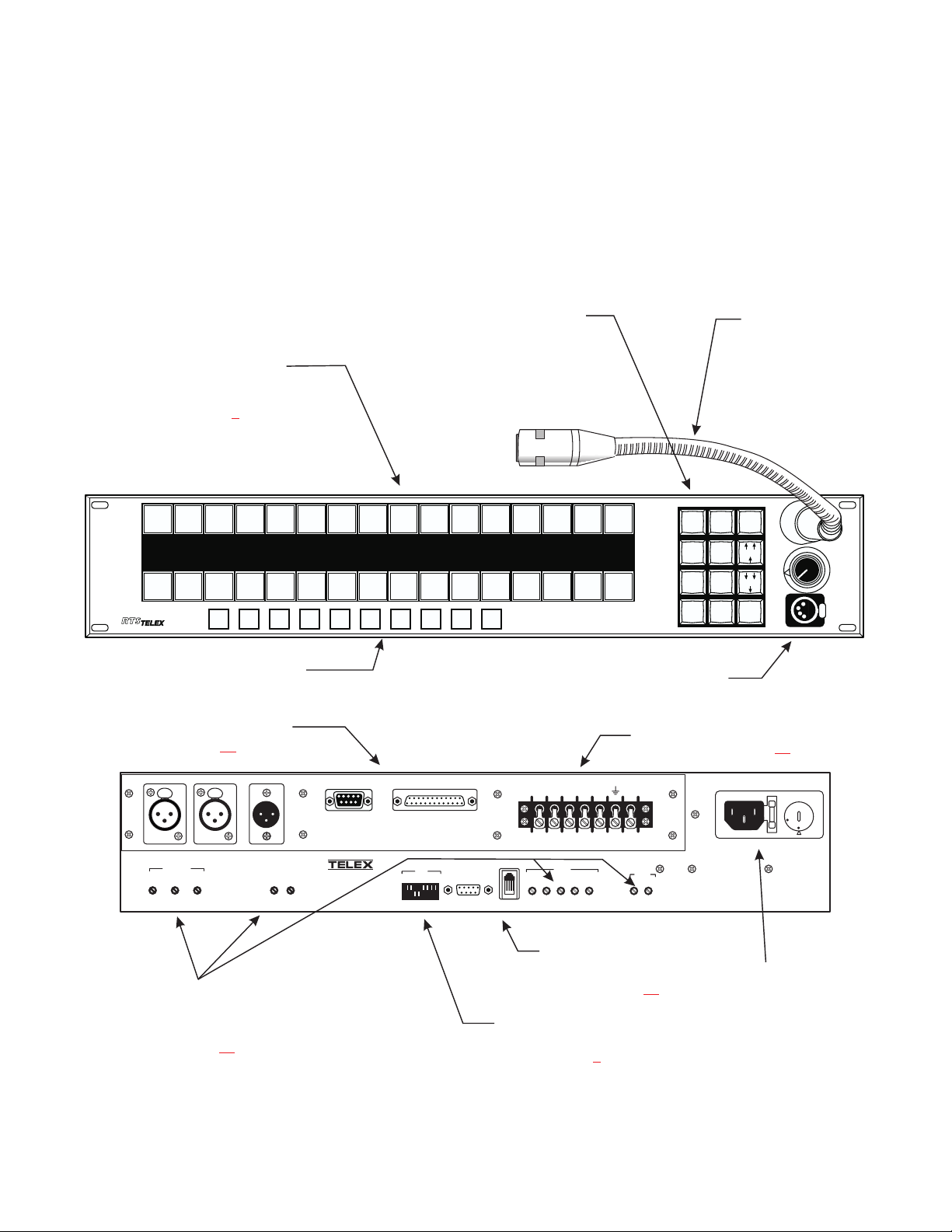
Figure 1. KP98-7 Reference View · · · · · · · · · · · · · · · · · · · · · · · · · · · · · · · · · · · · · · · · · · · · · · · · · · · · · · · 7
Figure 2. EKP98-0 Reference View· · · · · · · · · · · · · · · · · · · · · · · · · · · · · · · · · · · · · · · · · · · · · · · · · · · · · · · 8
Figure 3. LCP-100A Reference View· · · · · · · · · · · · · · · · · · · · · · · · · · · · · · · · · · · · · · · · · · · · · · · · · · · · · · 8
Figure 4. 9-pin Intercom cable wiring diagram · · · · · · · · · · · · · · · · · · · · · · · · · · · · · · · · · · · · · · · · · · · · · · · · 11
Figure 5. RJ-11 Intercom cable wiring diagram· · · · · · · · · · · · · · · · · · · · · · · · · · · · · · · · · · · · · · · · · · · · · · · · 11
Figure 6. Typical Interconnections between the KP98-7, EKP98-0, and LCP-100A · · · · · · · · · · · · · · · · · · · · · · · · · · · · · 12
Figure 7. Terminal block wiring diagram for KP-96-RC option · · · · · · · · · · · · · · · · · · · · · · · · · · · · · · · · · · · · · · · 12
Figure 8. Locations of internal jumpers and trimmers· · · · · · · · · · · · · · · · · · · · · · · · · · · · · · · · · · · · · · · · · · · · · 15
LIST OF TABLES
Table 1. DIP Switch Summary · · · · · · · · · · · · · · · · · · · · · · · · · · · · · · · · · · · · · · · · · · · · · · · · · · · · · · · · · 9
Table 2. 9-pin FRAME Connector Pin-out · · · · · · · · · · · · · · · · · · · · · · · · · · · · · · · · · · · · · · · · · · · · · · · · · · 11
Table 3. RJ-11 FRAME Connector Pin-out · · · · · · · · · · · · · · · · · · · · · · · · · · · · · · · · · · · · · · · · · · · · · · · · · · 11
Table 4. EXT MIC IN Connector Pin-out · · · · · · · · · · · · · · · · · · · · · · · · · · · · · · · · · · · · · · · · · · · · · · · · · · · 13
Table 5. EXT LINE IN Connector Pin-out · · · · · · · · · · · · · · · · · · · · · · · · · · · · · · · · · · · · · · · · · · · · · · · · · · 13
Table 6. Rear Panel Headset Connector Pin-out· · · · · · · · · · · · · · · · · · · · · · · · · · · · · · · · · · · · · · · · · · · · · · · · 13
Table 7. MIC PRE OUT Connector Pin-out · · · · · · · · · · · · · · · · · · · · · · · · · · · · · · · · · · · · · · · · · · · · · · · · · · 13
Table 8. Correspondence between address numbers and intercom port numbers for ADAM Intercom Systems· · · · · · · · · · · · · · · 20
6 Installation Instructions, KP98-7 Keypanel
1 INTRODUCTION
1.1 NEW FEATURES FOR VERSION 8.2
This manual describes the installation of the KP98-7 Keypanel and its accessories, the EKP98-7 Expansion Panel
and the LCP-100A Level Control Panel. The manual is
based on version 8.2 of the keypanel firmware. For operating information, refer to the KP98-7 Operating Instructions Manual, version 8.2.
Programming keypad.See
operating instruction manual
Talk and listen keys, with 4character alpha-numeric displays.Talk and listen keys
are reversible. See “Talk Key
Row Selection”, page 9
LISTEN1LISTEN2LISTEN3LISTEN4LISTEN5LISTEN6LISTEN7LISTEN8LISTEN9LISTEN10LISTEN11LISTEN12LISTEN13LISTEN14LISTEN
PL01
PROD RACK
TALK
1
TM
KP98-7
TALK2TALK
IFB4
TALK
3
4
Page2Page
Page
1
TD
TALK5TALK6TALK
3
NEWS
AD
Page
Level
4
7
for details.Internal speaker is
behind keypad.
SAT1
TEL1 TEL2 FLOR
TALK10TALK
TALK
9
PL
IFB
Scroll
Scroll
Phone
TALK
8
Headset
Version 8.2 adds support for the LCP-100A Level Control
Panel. Version 8.2 also changes the positions of some of
the function buttons at the bottom of the front panel and
replaces the P-P function button with a Mic Enable function button. Note: usage of some of the DIP switches has
also changed.
Optional panel
microphone for
use with internal
speaker.
CALL
15
CLEAR
DIR
CHYR
IS01 IS02
TALK13TALK14TALK
TALK
11
12
Mic
Enable
AUD1
CALL
15
ANSWER
NUM
1
SLIST
PHONE
4
RELAY
COPY CW
7
EX COPY
CLR
PREFIX
TYPE
E-PNL
DISPLAY
MULT
FUNC
PL
AUTO
2
3
IFB
ISO
5
6
8
9
0
PGM
PUSH
VOLUME
HEADSET
Function buttons.See operating
instruction manual for details.
Optional KP96-RC Rear Connector Module.See “Optional
Connections”, page 11
MIC LEVEL
CARBON
HDSTPNL
HDST
DYN
PUSH
EXT LINE IN
MIC PRE OUT
COMPR.
PUSH
EXT MIC IN
Level trimmers provide adjustment for non-standard levels.See “Electrical
Adjustments”, page 14
.
LEVEL
TO
MATRIX
HEADSET
TELEX COMMUNICATIONS,INC.
MADE IN U.S.A.
KP98-7
®
EXPANSION
SW1
1 OPEN 8
CLOSED
P11
P10
MIN
I/C
Configuration switches.
See “DIP Switch Settings”, page 9.
Figure 1. KP98-7 Reference View
Headset connector.May be
used instead of speaker and
panel microphone.
Terminal strip. See “Optional
Connections”, page 11.
+
-
+
AMP
OUT
-
AMP
GROUP
IN
MUTE
HDST
CALL
EXT
MUTE
LEVEL
SPKR HDST
SPKR
SPKR
OUT
IN
LEVEL
SIDE
MIN
SPKR
TONE
EXT
MUTE
Choice of DE9S or RJ11
intercom connector.See
“Connection to Intercom
Matrix”, page 10
.
CAUTION
DISCONNECT POWER
BEFORE OPENING
Fused power
entry module with
110/220 voltage
selector switch.
220
SERIAL No.
110
Installation Instructions, KP98-7 Keypanel 7
 Loading...