

Page 1
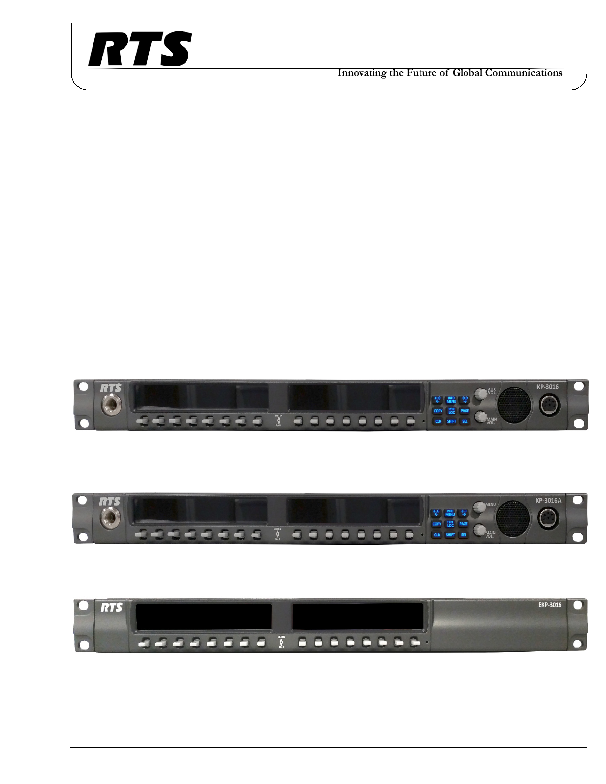
KP-3016 Keypanel
KP-3016A Keypanel
and
EKP-3016 Keypanel
Technical Manual
up to and including version 1.1.0
KP-3016
KP-3016A
EKP-3016
F.01U.315.927
Rev. 02
01/2017
Page 2
2 KP-3016/3016A Series
PROPRIETARY NOTICE
The product information and design disclosed herein were
originated by and are the property of Bosch Security Systems, Inc.
Bosch reserves all patent, proprietary design, manufacturing,
reproduction, use and sales rights thereto, and to any article
disclosed therein, except to the extent rights are expressly granted
to others.
COPYRIGHT NOTICE
Copyright 2016 by Bosch Security Systems, Inc. All rights
reserved. Reproduction, in whole or in part, without prior written
permission from Bosch is prohibited.
THE LIGHTNING
FLASH AND
ARROWHEAD
WITHIN THE
TRIANGLE IS A
WARNING SIGN
ALERTING YOU OF
“DANGEROUS
VOLTAGE” INSIDE
THE PRODUCT.
SEE MARKING ON BOTTOM/BACK OF PRODUCT.
CAUTION: TO REDUCE
THE RISK OF ELECTRIC
SHOCK, DO NOT REMOVE
COVER. NO USERSERVICABLE PARTS
INSIDE. REFER
SERVICING TO
QUALIFIED SERVICE
PERSONNEL.
THE EXCLAMATION
POINT WITHIN THE
TRIANGLE IS A
WARNING SIGN
ALERTING YOU OF
IMPORTANT
INSTRUCTIONS
ACCOMPANYING
THE PRODUCT.
*All other trademarks are property of their respective owners.
WARNING: APPARATUS SHALL NOT BE EXPOSED TO DRIPPING OR
SPLASHING AND NO OBJECTS FILLED WITH LIQUIDS, SUCH AS VASES,
SHALL BE PLACED ON THE APPARATUS.
WARRANTY AND SERVICE INFORMATION
For warranty and service information, refer to the appropriate web
site below:
RTS Intercoms .............................. www.rtsintercoms.com/warranty
RTS Digital
RTSTW
AudioCom
RadioCom
Intercom Headsets.................................................... www.telex.com
WARNING: THE MAIN POWER PLUG MUST REMAIN READILY OPERABLE.
CAUTION: TO REDUCE THE RISK OF ELECTRIC SHOCK, GROUNDING OF
THE CENTER PIN OF THIS PLUG MUST BE MAINTAINED.
WARNING: TO REDUCE THE RISK OF FIRE OR ELECTRIC SHOCK, DO NOT
EXPOSE THIS APPRATUS TO RAIN OR MOISTURE.
WARNING: TO PREVENT INJURY, THIS APPARATUS MUST BE SECURELY
ATTACHED TO THE FLOOR/WALL/RACK IN ACCORDANCE WITH THE
INSTALLATION INSTRUCTIONS.
CUSTOMER SUPPORT
Technical questions should be directed to:
Customer Service Department
Bosch Security Systems, Inc.
www.telex.com
TECHNICAL QUESTIONS EMEA
Bosch Security Systems Technical Support EMEA
http://www.rtsintercoms.com/contact_main.php
DISCLAIMER
The manufacturer of the equipment described herein makes
no expressed or implied warranty with respect to anything
contained in this manual and shall not be held liable for any
implied warranties of fitness for a particular application or
for any indirect, special, or consequential damages. The
information contained herein is subject to change without
prior notice and shall not be construed as an expressed or
implied commitment on the part of the manufacturer.
This product is AC only.
Bosch Security Systems, Inc.
Technical Manual
F.01U.315.927
Rev. 02
Page 3

KP-3016/3016A Series 3
Important Safety Instructions
1. Read these instructions.
2. Keep these instructions.
3. Heed all warnings.
4. Follow all instructions.
5. Do not use this apparatus near water.
6. Clean only with dry cloth.
7. Do not block any ventilation openings. Install in accordance with the
manufacturer’s instructions.
8. Do not install near any heat sources such as radiators, heat registers, stoves,
or other apparatus (including amplifiers) that produce heat.
9. Do not defeat the safety purpose of the polarized or grounding-type plug. A
polarized plug has two blades with one wider than the other. A grounding
type plug has two blades and a third grounding prong. The wide blade or the
third prong are provided for your safety. If the provided plug does not fit
into your outlet, consult an electrician for replacement of the obsolete outlet.
10. Protect the power cord from being walked on or pinched particularly at
plugs, convenience receptacles, and the point where they exit from the
apparatus.
11. Only use attachments/accessories specified by the manufacturer.
12. Use only with the cart, stand, tripod, bracket, or table specified by the
manufacturer, or sold with the apparatus. When a cart is used, use caution
when moving the cart/apparatus combination to avoid injury from tip-over.
13. Unplug this apparatus during lightning storms or when unused for long
periods of time.
14. Refer all servicing to qualified service personnel. Servicing is required
when the apparatus has been damaged in any way, such as power-supply
cord or plug is damaged, liquid has been spilled or objects have fallen into
the apparatus, the apparatus has been exposed to rain or moisture, does not
operate normally, or has been dropped.
Bosch Security Systems, Inc.
Technical Manual
F.01U.315.927
Rev. 02
Page 4

4 KP-3016/3016A Series
Bosch Security Systems, Inc.
Technical Manual
F.01U.315.927
Rev. 02
Page 5

Table
of
Contents
INTRODUCTION ....................................................................................................................... 11
Features ..................................................................................................................................................11
Specifications .........................................................................................................................................12
KP-3016/3016A Block Diagram ............................................................................................................14
Reference View – KP-3016 ...................................................................................................................15
Connector Pinouts ..................................................................................................................................16
INSTALLATION ........................................................................................................................ 17
Requirements .........................................................................................................................................17
KP-3016/KP-3016A Installation ............................................................................................................18
Connecting the Keypanel .......................................................................................................................19
Power Up ................................................................................................................................................21
Address Setting ......................................................................................................................................22
Connections ............................................................................................................................................23
BASIC OPERATION .................................................................................................................. 29
Intercom Keys and Displays ..................................................................................................................29
Keypad Reference View ........................................................................................................................32
INFO button ...........................................................................................................................................34
Menu Navigation and Shaft Encoder Knobs ..........................................................................................35
CLR Button ............................................................................................................................................35
Basic Intercom Key Operation ...............................................................................................................36
Crosspoint Gain Adjustment ..................................................................................................................37
Keypanel Volume Adjustments .............................................................................................................38
Aux Volume Adjustments (KP-3016 Only) ...........................................................................................39
Operation of Intercom Keys with Auto Functions .................................................................................40
Operation of Intercom Keys with Options .............................................................................................41
Operation of Intercom Talk Keys with the Speaker DIM Setting .........................................................41
Call Waiting Operation ..........................................................................................................................42
Graphical Call Waiting Window ............................................................................................................43
Mic Select ..............................................................................................................................................46
Setup Pages ............................................................................................................................................47
Menu Passwords ....................................................................................................................................48
Keypanel Color Window .......................................................................................................................49
Enhanced Tallies ....................................................................................................................................56
Flash Text Characteristics Window .......................................................................................................60
Show Icon Characteristics Window ...................................................................................................... 62
Bosch Security Systems, Inc.
Technical Manual
F.01U.315.927
Rev. 02
Page 6

6 KP-3016/KP-3016A Series
FIRMWARE DOWNLOAD ....................................................................................................... 67
Download Firmware to the KP-3016/3016A From AZedit .................................................................. 67
Download Firmware to the Keypanel Using the Firmware Upload Tool ............................................. 69
Download Firmware Using the Bootloader .......................................................................................... 72
Enable Downloading New Bootloader from the Keypanel ................................................................... 74
Display the FPGA Version .................................................................................................................... 74
Download and Upgrade the FPGA in the KP-3016/3016A .................................................................. 74
Download a Splash Screen .................................................................................................................... 77
Download a Font File ............................................................................................................................ 79
Download a Icon File ............................................................................................................................ 81
KP-3016/3016A MENU SYSTEM ............................................................................................. 85
Main Menu Access ................................................................................................................................ 85
Menu System, Audio Options ............................................................................................................... 86
Menu System, Display ........................................................................................................................105
Menu System, Key Assign Menu ........................................................................................................ 109
Menu System, Key Options Menu ...................................................................................................... 114
Menu System, OMNEO Offers (Only available for KP-3016) ........................................................... 120
Menu System, RVON Offers (Only available when an RVON-IO is detected) ................................. 120
Menu System, Save Config ................................................................................................................. 121
Menu System, Service ......................................................................................................................... 122
CENTRALIZED AUTO-DIALING ......................................................................................... 137
Centralized Auto Dials ........................................................................................................................ 137
Receiving A Phone Call ...................................................................................................................... 140
Hanging Up ......................................................................................................................................... 140
KEYPANEL MENU QUICK REFERENCE .......................................................................... 141
Audio Options ..................................................................................................................................... 141
Display Menu ...................................................................................................................................... 146
Key Assign Menu ................................................................................................................................ 147
Key Options Menu .............................................................................................................................. 148
OMNEO Offers Menu (KP-3016 Only) .............................................................................................. 150
Save Config Menu ............................................................................................................................... 150
Service Menu ....................................................................................................................................... 151
UNICODE SUPPORT .............................................................................................................. 155
AZedit and Unicode Support ............................................................................................................... 155
POWER SUPPLY MOUNTING .............................................................................................. 159
Mounting the Power Supply to a Standard Rack ................................................................................159
EKP-3016 .................................................................................................................................. 161
Introduction ......................................................................................................................................... 161
Specifications ...................................................................................................................................... 161
EKP-3016 Expansion Panel Reference View .....................................................................................162
Expansion Panel Cabling Reference ................................................................................................... 162
Mounting the Power Supply to the EKP-3016 .................................................................................... 163
Bosch Security Systems, Inc.
Technical Manual
F.01U.315.927
Rev. 02
Page 7

List
of
Figures
FIGURE 1. KP-3016/3016A Audio Flow Block Diagram .................................................................. 14
FIGURE 2. KP-3016 Reference View ................................................................................................. 15
FIGURE 3. KP-3016A Reference View .............................................................................................. 15
FIGURE 4. KP-3016/3016A Installation ............................................................................................. 18
FIGURE 5. Female Headset Connector Set Screw Access Hole ......................................................... 24
FIGURE 6. Male Headset Connector Set Screw Access Hole ............................................................. 25
FIGURE 7. KP-3016 Keypad ............................................................................................................... 32
FIGURE 8. KP-3016 AUX VOL. Knob and KP-3016A MENU Knob ............................................... 35
FIGURE 9. Key Function Position Explanation .................................................................................. 36
FIGURE 10. Talk/Listen Indicators ....................................................................................................... 37
FIGURE 11. Graphical Call Waiting Window ...................................................................................... 43
FIGURE 12. Graphical Call Waiting Window Highlighted Call ........................................................... 44
FIGURE 13. Keypanel Colors Window ................................................................................................. 49
FIGURE 14. Color Grid ......................................................................................................................... 51
FIGURE 15. Key Assignments Page ..................................................................................................... 52
FIGURE 16. Assignments Groups Page ................................................................................................ 53
FIGURE 17. Miscellaneous Colors Page ............................................................................................... 55
FIGURE 18. Flash Text Characteristics Window .................................................................................. 60
FIGURE 19. Show Icon Characteristic Window ................................................................................... 62
FIGURE 20. Tally (key) icon 512x64 pixel bitmap of key icons .......................................................... 64
FIGURE 21. 512 x128 pixel bitmap of panel icons ............................................................................... 65
FIGURE 22. Automatic Gain Control Example .................................................................................... 87
FIGURE 23. Mounting Bracket – Horizontal on a Crossbar ............................................................... 159
FIGURE 24. Mounting Bracket – Vertical from a Crossbar ................................................................ 160
FIGURE 25. EKP-3016 Expansion Panel Reference View - Front and Rear ...................................... 162
FIGURE 26. Expansion Panel Cabling ................................................................................................ 162
Bosch Security Systems, Inc.
Technical Manual
F.01U.315.927
Rev. 02
Page 8

10 KP-3016/KP-3016A Series
Bosch Security Systems, Inc.
Technical Manual
F.01U.315.927
Rev. 02
Page 9

CHAPTER 1
Introduction
Part of the KP-Series keypanel family, the KP-3016 provides the same superior digital audio as the flagship KP-4016 model,
by using OMNEO media networking technology (developed by RTS parent company Bosch and incorporating Dante
high-quality audio over IP). The analog-only KP-3016A is also available. Both versions deliver top-notch sound quality, free
of noise, delay, and other artifacts sometimes present in older technology.
Features
• Wide viewing-angle color screen
• Ergonomic levers for talk/listen
• Full support for OMNEO - KP-3016 Only
• Support for 4-wire analog connection
• Expansion panel option available.
• Built-in speaker.
• Microphone input for dynamic or electret mics
• User-replaceable XLR headset connector – 4- or 5-pin available
Bosch Security Systems, Inc.
Technical Manual
F.01U.315.927
Rev. 02
Page 10

12 Introduction KP-3016/KP-3016A Series
Specifications
LCD Display
KP-3016/3016A:
Active Area ................. 120.10mm (wide) x 18.77mm (high)
Dot Resolution................................................576 x 90 pixels
Color Resolution ..............................16-bit (64K) RGB color
View Angle.......................80 degrees (typical; all directions)
Power Supply:
Type:.....................................................................External DC
AC Input:............................................. 100–240VAC 50/60Hz
Inputs:
Matrix
Type........................................................................... Balanced
Typical Input Level ....................................................... +8dBu
Typical Input Impedance...............................................>10kΩ
Maximum Input Level.................................................+20dBu
Supported Bandwidth.....................................100Hz to 20kHz
Panel Mic
Type..............................................................................Electret
Typical Input Level ...................................................... -42dBu
Headset
Maximum
Output Power ......................................... 125mW for 32Ω load
Earphone Impedance ....................................... 16Ω and above
THD+N%.....................................................................<0.20%
Frequency Response ...................................... 100Hz to 20kHz
Speaker
SPL ......................... 84dBSPL for 1kHz sine wave @ 1 meter
Digital (KP-3016 Only):
OMNEO Channels
Typical OMNEO Latency...............................................1.0ms
Frequency Response ..........................................20Hz - 20kHz
Environmental:
Dimensions
KP-3016
17.39” W (without rack ears) x 1.72” H x 3.88” D
(441.82mm x 43.8mm x 98.5mm
[111.11mm including volume knobs and lever keys])
KP-3016A
17.39” W (without rack ears) x 1.72” H x 3.88” D
(441.82mm x 43.8mm x 98.5mm
[111.11mm including volume knobs and lever keys])
Typical Input Impedance................................................1.0kΩ
Maximum Input Level..................................................-25dBu
Headset Mic - Electret
Typical Input Level ...................................................... -42dBu
Typical Input Impedance................................................1.0kΩ
Maximum Input Level..................................................-25dBu
Headset Mic - Dynamic
Typical Input Level ...................................................... -50dBu
Typical Input Impedance.................................................600Ω
Maximum Input Level..................................................-25dBu
Outputs:
Matrix
Type........................................................................... Balanced
Typical Output Level.....................................................+8dBu
THD+N% .................................................................... <0.20%
Typical Output Impedance .............................................. 600Ω
Maximum Output Level .............................................. +20dBu
Weight
KP-3016..........................................................3.35 lb (1.52kg)
KP-3016A .......................................................3.35 lb (1.52kg)
Power Supply.................................................. 0.53lb (0.24kg)
Power Supply
Mounting Bracket ......................................... 0.30lb (0.14kg)
Tem pe ra tu re
Operating ................................... 0°C to 55°C (32°F to 131°F)
Storage .....................................-20°C to 70°C (-4°F to 158°F)
Frequency Response.......................................100Hz to 20kHz
Bosch Security Systems, Inc.
Technical Manual
F.01U.315.927
Rev. 02
Page 11

KP-3016/KP-3016A Series Introduction 13
Power Consumption:
KP-3016
Nominal..................................................................... 11 Watts
Maximum ................................................................... 13 Watts
Maximum Volt Amp ......................................................36 VA
KP-3016A
Nominal........................................................................ 8 Watts
Maximum .................................................................. 10 Watts
Maximum Volt Amp ..................................................... 36 VA
Certification:
CE Compliance
• EMC
• EN55022 Class A
• VCCI Class A
• ICES-003
• FCC Part 15 Subpart B Class A
• AS/NZS CISPR22 Class A
• Korean KN 22
• EN 55024
• Korean KN 61000-4
• BSMI Class B
Safety
• UL 60950-4
• EN60950-1
• CB Report
• PSE
Bosch Security Systems, Inc.
Technical Manual
F.01U.315.927
Rev. 02
Page 12
14 Introduction KP-3016/KP-3016A Series
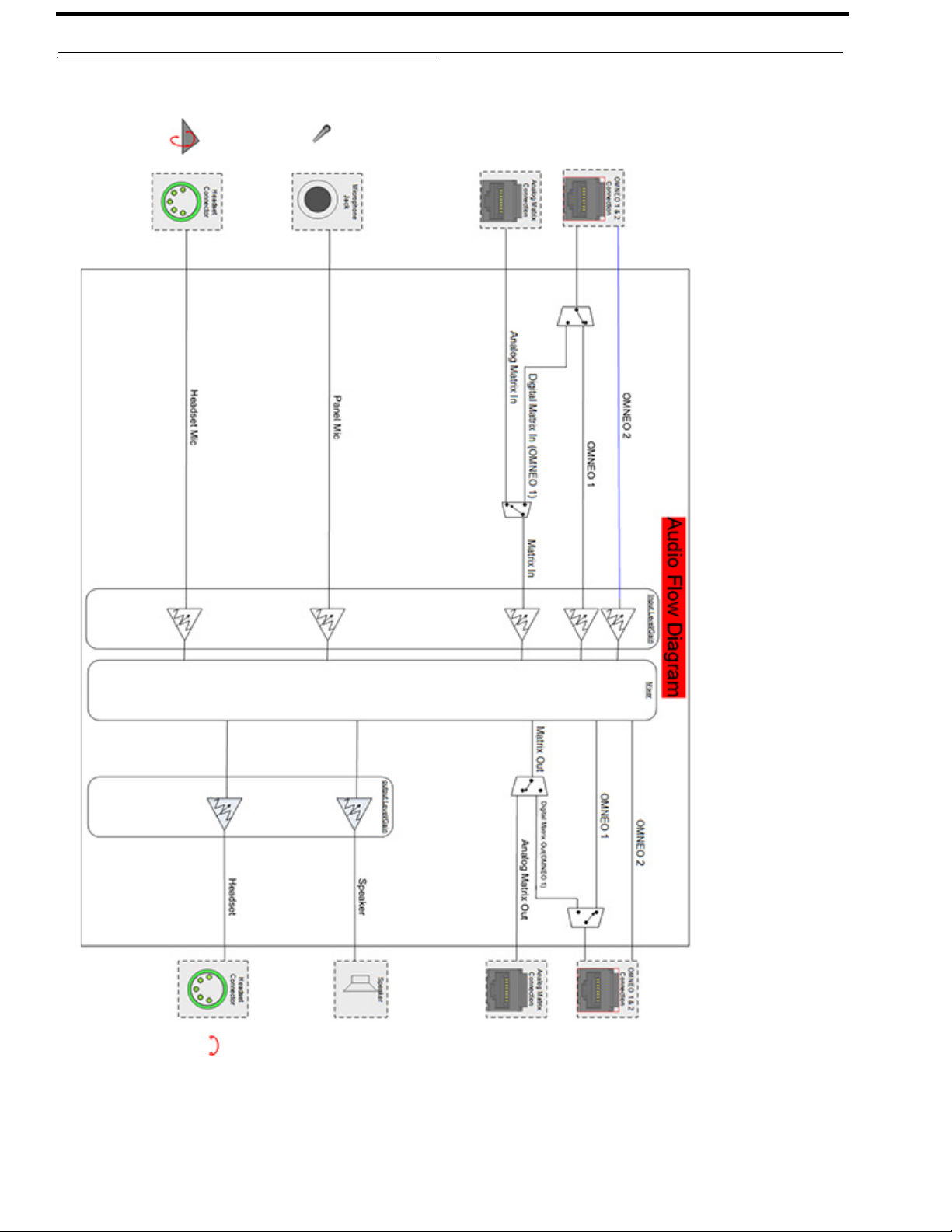
KP-3016/3016A Block Diagram
FIGURE 1. KP-3016/3016A Audio Flow Block Diagram
Bosch Security Systems, Inc.
Technical Manual
F.01U.315.927
Rev. 02
Page 13
KP-3016/KP-3016A Series Introduction 15
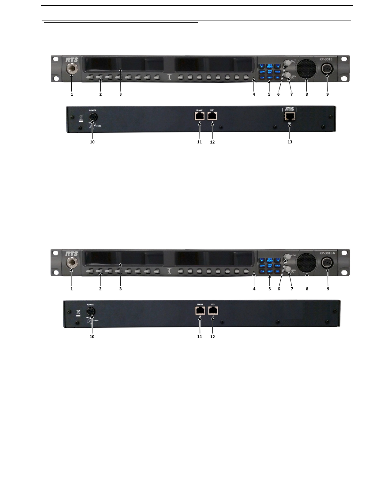
Reference View – KP-3016
FIGURE 2. KP-3016 Reference View
1. Microphone Connector
2. Lever Keys
3. LCD Display
4. Keypanel Reset
5. Keypad
6. AUX VOL. Encoder Knob/Menu Navigation
7. MAIN VOLUME Knob
8. Speaker
9. Headset Connector
10. POWER Connector
11. FRAME Connector
12. EXP Connector
13. OMNEO ETHERNET Connector (See “Ethernet
Connector (KP-3016 ONLY)” on page 23)
FIGURE 3. KP-3016A Reference View
1. Microphone Connector
2. Lever Keys
3. LCD Display
4. Keypanel Reset
5. Keypad
6. AUX VOL. Encoder Knob/Menu Navigation
7. MAIN VOLUME Knob
8. Speaker
9. Headset Connector
Bosch Security Systems, Inc.
10. POWER Connector
11. FRAME Connector
12. EXP Connector
Technical Manual
F.01U.315.927
Rev. 02
Page 14

16 Introduction KP-3016/KP-3016A Series
Connector Pinouts
Power Supply: J1
Pin Assignment
Pin 1 24VDC
Pin 2 GND
Pin 3 Chassis GND
Matrix Connector: J8
a
Pin RJ-45 RJ-12
1 RS485 +
2 RS485 - RS485 3 FROM MATRIX + FROM MATRIX +
4 TO MATRIX + TO MATRIX +
5 TO MATRIX - TO MATRIX 6 FROM MATRIX - FROM MATRIX 7 RS485 + RS485 +
8 RS485-
a. Supports 568B and USOC wiring
EXP Connector: J9
Pin Assignment
1
2
3
4 GND
5 GND
6
7 RS485 +
8 RS485 -
ETHERNET: J11 (only for KP-3016, not KP-3016A)
Pin Assignment
1 Data 1 +
2 Data 1 3 Data 2 +
4 Data 3 +
5 Data 3 6 Data 27 Data 4+
8 Data 4-
Panel Mic
Pin Assignment
Tip PANEL_MIC_IN +
Ring
Sleeve CGND
PAN E L _ MIC _ I N -
Headset
Assignment
Pin
1 HS_MIC_IN- HS_MIC_IN-
2 HS_MIC_IN+ HS_MIC_IN+
3 HS_COMMON HS_COMMON
4 HS_L_OUT HS_L_OUT
5HS_R_OUT
4-Pin 5-Pin
Bosch Security Systems, Inc.
Technical Manual
F.01U.315.927
Rev. 02
Page 15

Requirements
The following keypanel firmware versions are needed for the specified KP-3016/3016A model:
AZedit................. V5.2.0 or later
IPedit.................. V3.2.0 or later
MCII-e................ V3.2.0 or later
CHAPTER 2
Installation
AIO-16................ V1.6.0 or later
FWUT................. V3.3.0 or later (3016 Only)
DNS-SD.............. V3.3.0 or later (3016 Only)
OMI .................... V5.2.0 or later (3016 Only)
Bosch Security Systems, Inc.
Technical Manual
F.01U.315.927
Rev. 02
Page 16

18 Installation KP-3016/3016A Series
KP-3016/KP-3016A Installation
IMPORTANT: If you plan to use the Power Supply Mounting Bracket, we recommend you install the mounting bracket
before cabling the keypanel. For information on different power supply mounting options, see “Power
Supply Mounting” on page 159.
FIGURE 4. KP-3016/3016A Installation
IMPORTANT: When the OEI-2 power supply is used on a KP-3016/3016A keypanel, the following warning blinks to
indicate the wrong power supply being used. The OEI-2 uses less voltage than the keypanel, therefore,
when the power supply for the OEI-2 is used on a keypanel, degraded audio may be heard. No damage
to the keypanel occurs.
To install the KP-3016/3016A, do the following:
1. On the rear panel of the KP-3016/3016A, plug the 24 VDC power connector (A) of the power supply into the power
connector on the back panel of the unit.
2. Connect an RJ-12 or RJ-45 (568B or USOC) cable (B) with RTS cabling to the J8 FRAME connector on the rear
panel.
OR
Connect an CAT-5e cable (C) to the J11 ETHERNET connector on the rear panel (only available for the KP-3016)
3. Once the unit is cabled, plug the power supply power cord into the wall outlet or a power strip.
Bosch Security Systems, Inc.
Technical Manual
F.01U.315.927
Rev. 02
Page 17

KP-3016/3016A Series Installation 19
Connecting the Keypanel
IMPORTANT: OMNEO is not available on the KP-3016A.
You can connect the OMI using AZedit and IPedit; however, only IPedit can be used to connect the keypanel.
Configure the OMI using AZedit
To connect the OMI to the KP-3016 using AZedit, do the following:
1. From the Status menu in AZedit, select I/O Cards.
The I/O Card Status window appears showing a list of installed cards.
2. Right-click the OMI card you want to connect to the keypanel.
A pop-up menu appears.
3. From the pop-up menu, select OMNEO Configuration.
The OMNEO Configuration window appears.
4. From the OMNEO card drop down menu, select the slot number where the OMI card is located in the frame.
The Device Name field auto-populates with the name of the device.
5. From the Local Channel drop down menu, select the channel you want to use to communicate to your keypanel
across the network.
NOTE: Channels not already configured to connect to another device appear with an asterisk (*) next to them.
6. In the Partner Device Name field, enter the name of keypanel you want to use to communicate with. Or, select the
Browse icon to select from a list of devices.
OR
In the Partner IP Address field, enter the IP Address of the device to which you want to connect. This field autopopulates when you select the Device Name.
7. From the Partner Device Type drop down menu, select the type of device to which the OMI card is connecting.
8. From the Partner Channel drop down menu, select channel 1 on the device to which the OMI communicates.
9. Once you are completely finished, click Apply.
Apply sends the changes to the cards in the intercom, or Click Cancel to discard all the changes made.
Add the OMI to the Device Catalog in IPedit
To add the keypanel to IPedit, do the following:
1. Open IPedit.
2. From the Device menu, select Add.
The Add Devices Window appears, open to the Search tab.
3. Select the OMI card.
The Add button becomes active.
4. Click the Add button.
The OMI card appears in the device catalog in the left panel.
5. Click the Done button.
The Add Devices window closes.
Configure the OMI using IPedit
To configure the OMI using IPedit, do the following:
Using the Device Configuration and Status Pane
Bosch Security Systems, Inc.
Technical Manual
F.01U.315.927
Rev. 02
Page 18

20 Installation KP-3016/3016A Series
1. In the Device Name field, enter a device name familiar to you, if desired.
Initially OMI cards are given a default name.
IMPORTANT: If you change the device name, this causes the device to reboot. It is not necessary to change the device
name. However, if you do change the name, it is best to do this early in the setup so you do not have to
revisit other devices that connect to this device and update them later.
2. In the Description field, enter a description for the OMI card, if desired.
Using the Channel Configuration and Status Section:
3. In the Channel Description field, enter a channel description, if applicable.
4. From the Destination Type drop down menu, select OKP.
5. In the Destination Device Name field, enter the name of the device to which the channel will connect.
OR
Click the... button.
The Discovered Devices Window appears.
Expand the tree to view the available devices.
From the expanded tree, select the device to which you want to connect.
Click OK.
6. From the Destination Channel drop down menu, select the channel to which the OMI will connect.
7. Send the changes to the OMI.
Add the KP-3016 to the Device Catalog in IPedit
To add the keypanel to IPedit, do the following:
1. Open IPedit.
2. From the Device menu, select Add.
The Add Devices Window appears, open to the Search tab.
3. Select the keypanel.
The Add button becomes active.
4. Click the Add button.
The keypanel appears in the device catalog in the left panel.
5. Click the Done button.
The Add Devices window closes.
Configure the KP-3016 using IPedit
To configure the keypanel using IPedit, do the following:
Using the Device Configuration and Status Pane
1. In the Device Name field, enter a device name familiar to you, if desired.
Initially, keypanels are given a default name.
IMPORTANT: If you change the device name, this causes the device to reboot. It is not necessary to change the device
name. However, if you do change the name, it is best to do this early in the setup so you do not have to
revisit other devices that connect to this device and update them later.
2. In the Description field, enter a description for the keypanel, if desired.
Using the Channel Configuration and Status Section:
3. In the Channel Description field, enter a channel description, if applicable.
Bosch Security Systems, Inc.
Technical Manual
F.01U.315.927
Rev. 02
Page 19

KP-3016/3016A Series Installation 21
4. From the Destination Type drop down menu, select OMI.
5. In the Destination Device Name field, enter the name of the device to which the channel will connect.
OR
Click the... button.
The Discovered Devices Window appears.
Expand the tree to view the available devices.
From the expanded tree, select the device to which you want to connect this keypanel.
Click OK.
6. From the Destination Channel drop down menu, select the channel to which this keypanel will connect.
7. Send the changes to the keypanel.
Connecting the KP-3016 through the OMNEO Offers Menu
IMPORTANT: If you used IPedit to set up the keypanel connection, this step not needed, because you have already
done this in the software.
If you used AZedit to set up the keypanel connection, the keypanel needs to be set up to talk with the OMI card in the frame.
To do this, a connection needs to be established using the OMNEO Offers menu on the keypanel. For more information, see
“Menu System, OMNEO Offers (Only available for KP-3016)” on page 120.
To configure a connection offer, do the following:
1. Starting at the OMNEO Offers|Keypanel menu, select OKP.
2. Press the SEL button.
A list of available OMNEO offers appears.
3. Using the AUX/MENU shaft encoder, select the OMNEO offer you want to use.
An arrow appears next to the device.
4. Press the CLR button to exit menu mode.
Power Up
At power-up, if the keypanel is connected to the matrix, the alphanumeric display shows dashes in the light blue color key
. After several seconds, the intercom key assignments are shown with the appropriate color keys and alphas.
NOTE: If the keypanel cannot establish communications with the intercom system, all keys continue to show asterisks
(****) and the Disconnected from Matrix icon appears in the panel display. If the keypanel is
configured for OMNEO, this icon also displays the OMNEO device name. Check the keypanel to matrix cable
connection if this occurs. If the keypanel loses communications with the intercom, the panel display shows the
Disconnected from Matrix icon and displays the after approximately 30 seconds.
Bosch Security Systems, Inc.
Technical Manual
F.01U.315.927
Rev. 02
Page 20

22 Installation KP-3016/3016A Series
Address Setting
General Information
In ADAM intercoms using AIO-8 cards or AIO-16 cards with SCSI breakouts, and in ADAM-CS and Zeus/Zeus II intercoms,
the intercom ports share data connections in groups of eight (8). Each keypanel is uniquely identified on the data port by its
address. The method of determining the proper address varies for each intercom system. Use the method for your intercom
system, as described on the following pages.
TABL E 1 . KP-3016/3016A Addressing
Manually Addressed Automatically Addressed
You must manually address
following
:
• AIO-8 on ADAM
• AIO-16 SCSI on ADAM
• ADAM CS
• Zeus I
• Zeus II
a
the keypanel when using the
The keypanel address is automatically detected when using
the following:
• AIO-16 MDR on ADAM and ADAM-M
• Cronus
• Zeus III and Zeus III LE/LE+
• RVON Products - RVON-8, RVON-2,
RVON-C, and RVON-16
NOTE: Keypanels using RVON-I/O may need to be
individually addressed. See the RVON-I/O user
manual for further instruction.
a. To manually address the KP-3016/3016A, see “Service Menu, Set Address” on page 133.
To see specific addressing information for:
• ADAM with AIO-8 cards, see the ADAM technical manual (P/N F01U216986).
• ADAM CS, see the ADAM CS technical manual (P/N 93307517000).
• ADAM and ADAM-M with AIO-16 cards, see the AIO-16 user manual (P/N F01U193267).
• Cronus, see Cronus user manual (P/N F01U118890).
• Zeus III, see the Zeus III user manual (P/N F01U193289).
• Zeus III LE/LE+, see the Zeus III LE/LE+ user manual (P/N F01U193290).
NOTE: If you are connecting to an ADAM or ADAM-M frame with AIO-16 cards using MDR connectors or a Cronus
frame, you do not need to set the address. If the AIO-16 is using SCSI breakouts, you must set the address.
Bosch Security Systems, Inc.
Technical Manual
F.01U.315.927
Rev. 02
Page 21
KP-3016/3016A Series Installation 23
Connections
Frame Connector
Use the Frame connector to connect to an intercom port of the intercom system. For the frame connector location, see Figure 3
on page 15. The intercom port you connect to should agree with the address you set previously.
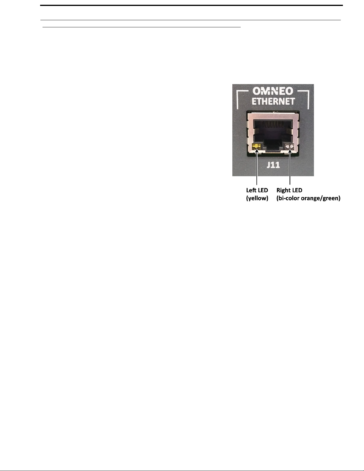
Ethernet Connector (KP-3016 ONLY)
Use the Ethernet connector to connect the keypanel to a network system. Each
RJ-45 Ethernet connector has two (2) LEDs:
Left LED. The left LED is yellow and indicates a network link is established.
It flashes on/off whenever there is network activity.
Right LED. The right LED is bi-color (orange and green) and indicates the
speed of the connection by the color that is displayed.
• A green LED indicates the port is operating at 1000Mbps (1 Gbps).
• An orange LED indicates the port is operating at 100Mbps.
• No LED color indicates the port is operating at 10Mbps. This is not
suitable for OMNEO networking.
Panel Microphone Connector
A panel microphone may be connected to the front of the unit. The connector accepts MCP5, MCP6, or MCP90 series panel
microphones. Insert the microphone and rotate the entire microphone body clockwise several turns to lock it in place.
Bosch Security Systems, Inc.
Technical Manual
F.01U.315.927
Rev. 02
Page 22
24 Installation KP-3016/3016A Series
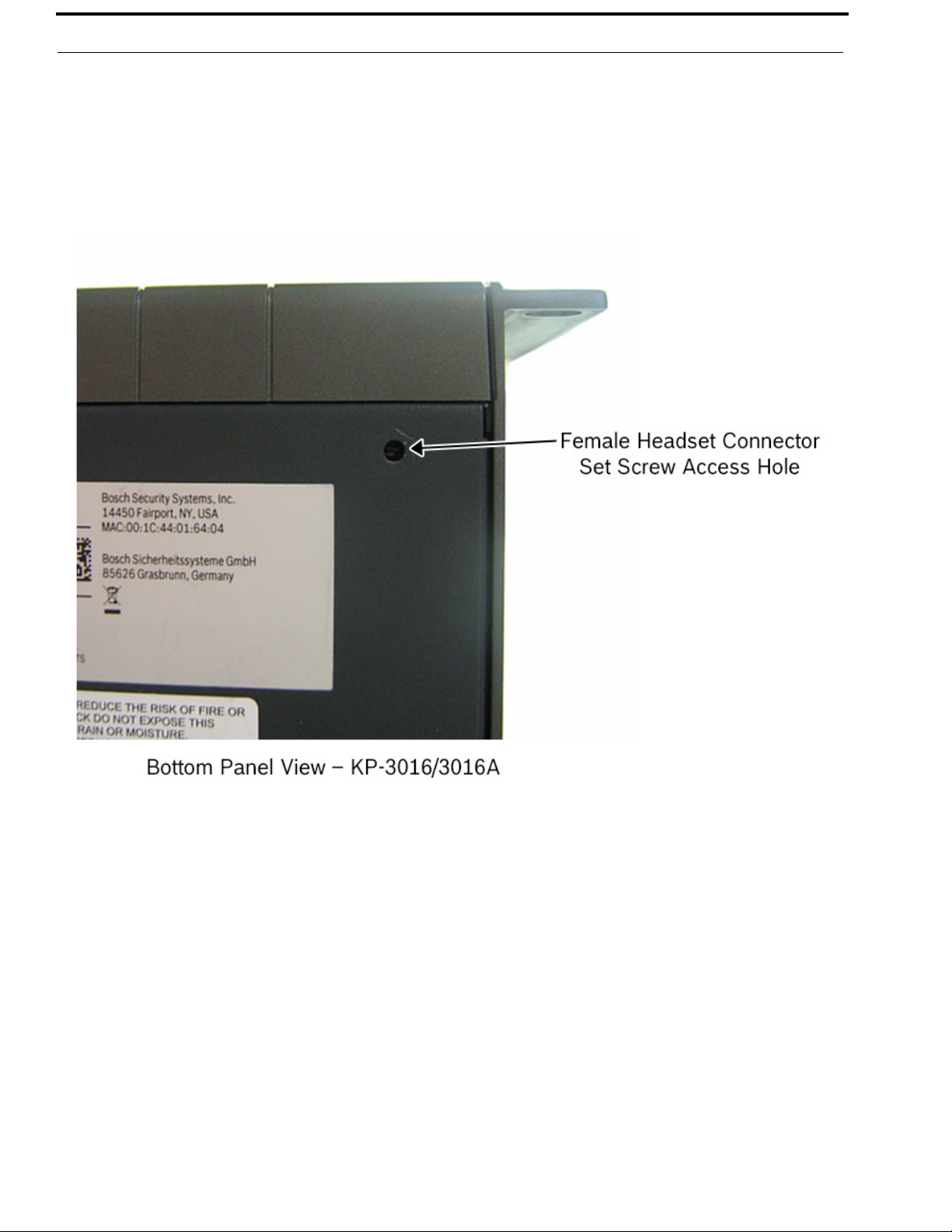
Headset Connector
A stereo headset may be connected to the front of the unit for use along with or in place of the front panel speaker and a
separate microphone. Headphones may be connected for use with a separate microphone.
Female Headset Connector
For a female headset connector, the set screw access hole is located on the bottom-right side of the unit.
FIGURE 5. Female Headset Connector Set Screw Access Hole
Bosch Security Systems, Inc.
Technical Manual
F.01U.315.927
Rev. 02
Page 23
KP-3016/3016A Series Installation 25
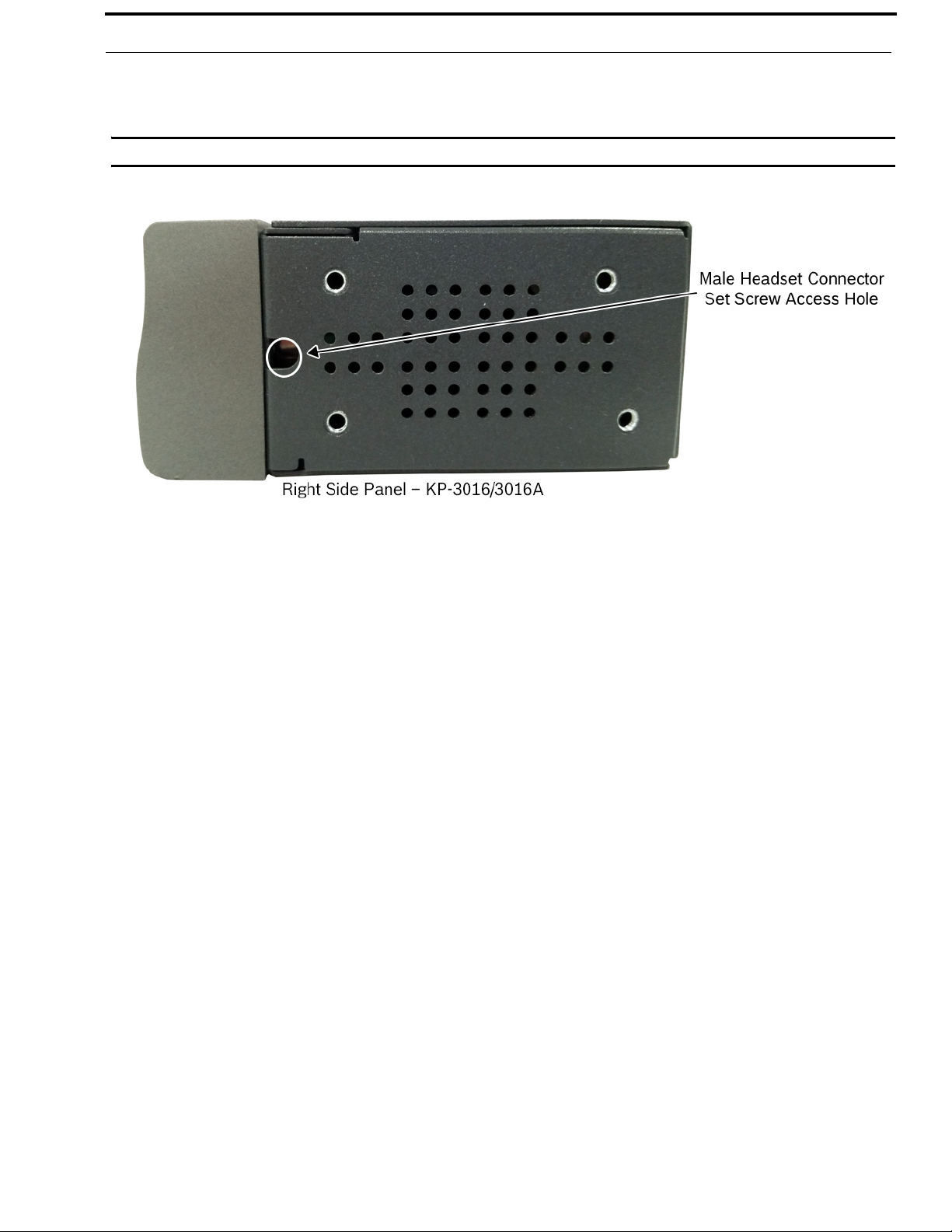
Male Headset Connector
For a male headset connector, the set screw access hole is located on the right-side of the unit.
IMPORTANT: The right-side rack ear must be removed to expose the set screw access hole.
FIGURE 6. Male Headset Connector Set Screw Access Hole
Bosch Security Systems, Inc.
Technical Manual
F.01U.315.927
Rev. 02
Page 24
26 Installation KP-3016/3016A Series
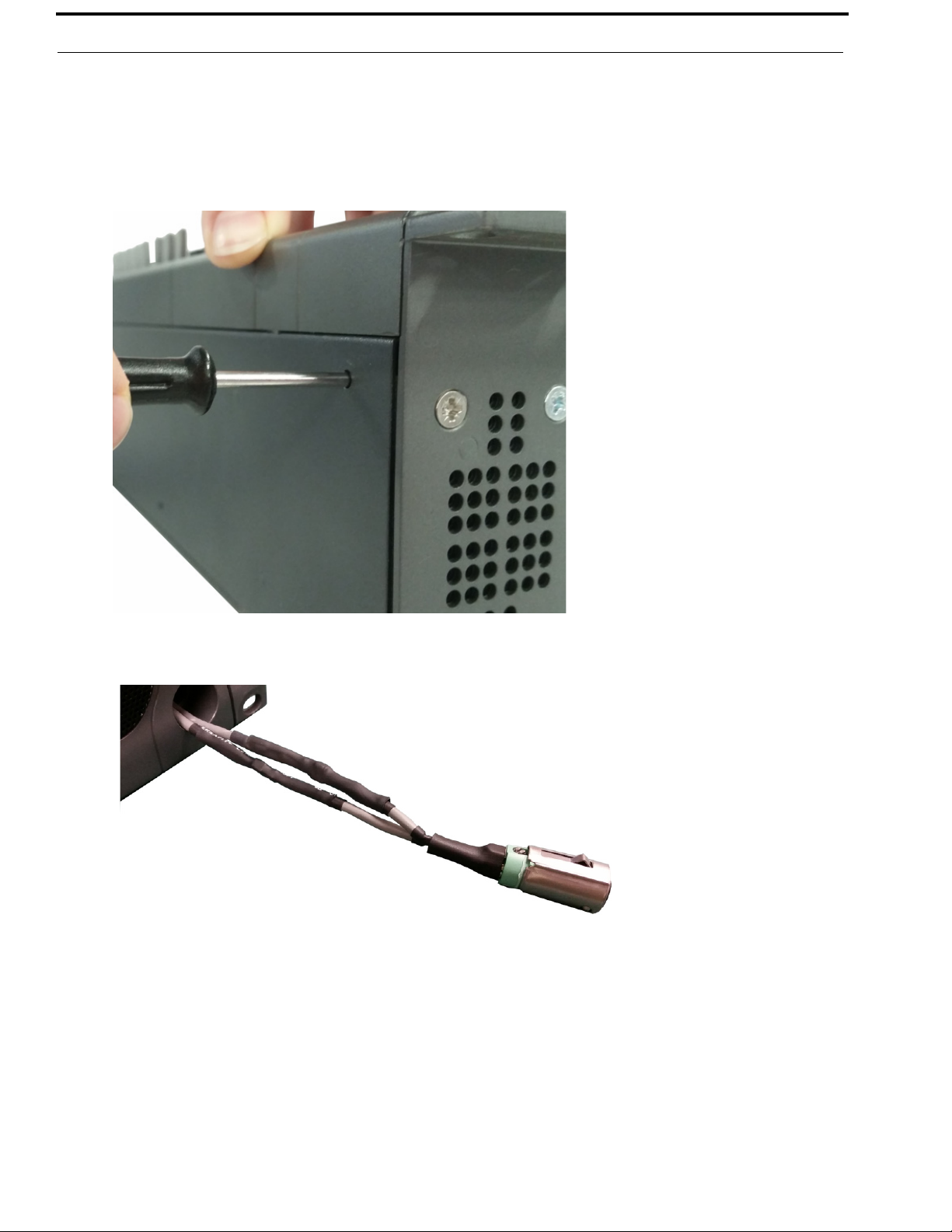
Changing the Headset Connector
The headset connector can be switched between a 4-pin XLR and 5-pin XLR (also compatible with 6-pin) connector.
To replace the front panel headset connector, do the following:
1. Using a flat-blade screwdriver with 2.4 mm wide (3/32 in.) tip, turn the set screw counterclockwise to loosen the
connector from the unit.
2. Once the connector is loose, tip the unit and gently shake the connector loose.
3. Carefully pull the headset cables free from the chassis.
NOTE: If the cable assembly becomes caught, shift the cable up and down to clear the cable from the unit.
Bosch Security Systems, Inc.
Technical Manual
F.01U.315.927
Rev. 02
Page 25
KP-3016/3016A Series Installation 27
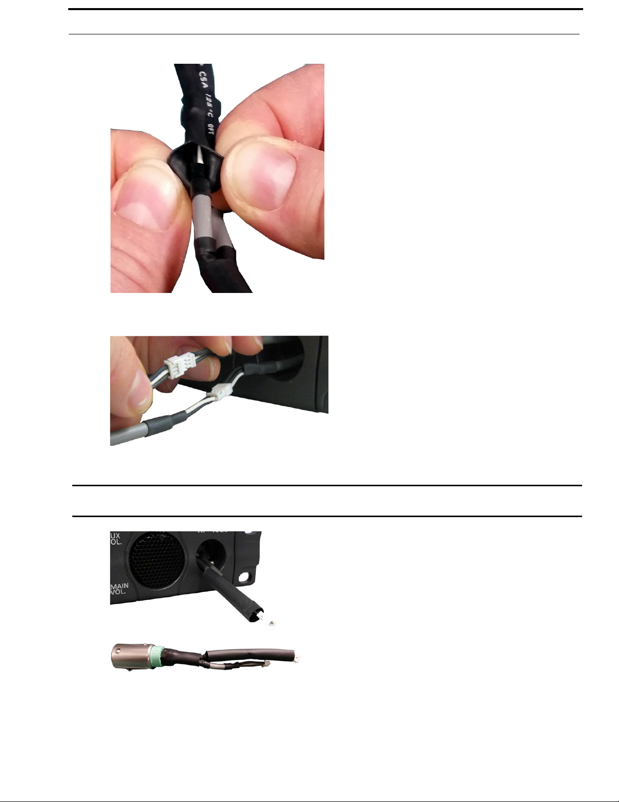
4. Cut the shrink-tubing from around the cables. Pay attention not to cut through the cables.
5. Disconnect both cables by pulling the cable-to-cable connectors apart.
6. Using the replacement headset connector, thread the cables through the supplied shrink-tubing.
IMPORTANT: You must thread the shrink tubing on the long cable on the replacement connector and the long cable
protruding from the keypanel headset connector opening.
7. Connect the cable-to-cable connectors.
NOTE: Take care to reconnect the proper gender connectors when reassembling the headset cable.
Bosch Security Systems, Inc.
Technical Manual
F.01U.315.927
Rev. 02
Page 26
28 Installation KP-3016/3016A Series
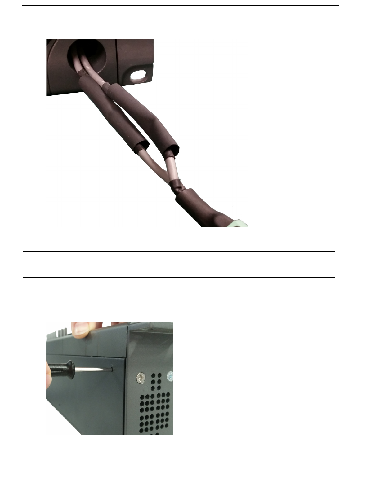
8. Position both pieces of shrink-tubing so any portion of the cable without an outer insulation layer is covered.
9. Using a heat gun, apply even heat over the length and diameter of the tubing (minimum temperature 100°C).
IMPORTANT: Since uncontrolled heat can cause uneven shrinkage, physical damage, and insulation failure, the use of
open flame is not recommended. Avoid overheating the heat shrink-tubing because it can become brittle
and/or charred.
10. Gently push the headset connector cable back into the unit.
11. Align the rib on the headset connector with the notch in the connector opening and press the connector
completely in.
12. While holding the connector in place, turn the set screw clockwise to tighten the connector in position.
Bosch Security Systems, Inc.
Technical Manual
F.01U.315.927
Rev. 02
Page 27
CHAPTER 3
Basic Operation
Intercom Keys and Displays
Color Display Descriptions for Intercom Keys
The KP-3016/KP3016A display uses key colors to distinguish the type of key assignment programmed on each key. Use
Table 2, to help you determine the available key assignment colors.
You can customize these colors to your preference by using the “Keypanel Color Window” on page 49.
TABL E 2 . Default Key Colors
Default Color Description
Amber Waiting for Footswitch
Bright Green Listen Indicator, Local Matrix
Brown IFB Special List
Teal Point-to-Point
Dark Yellow ISO
Light Blue Unassigned, Test Mode (with Talk and Listen Indicators)
Pale Yellow Special Functions
Magenta Relay
Pink Party Line
Red Remote Matrix
Salmon IFB, Talk Indicator
Pale Green Special List
Periwinkle UPL Resource
Bosch Security Systems, Inc.
Technical Manual
F.01U.315.927
Rev. 02
Page 28
30 Basic Operation KP-3016/KP-3016A Series
Display Icons
Display Icons are used to indicate the accessories and features enabled, disabled, active, and inactive. Use Table 3 for a
complete description of each icon seen on the KP-3016/3016A.
TABL E 3 . Display Icon Descriptions
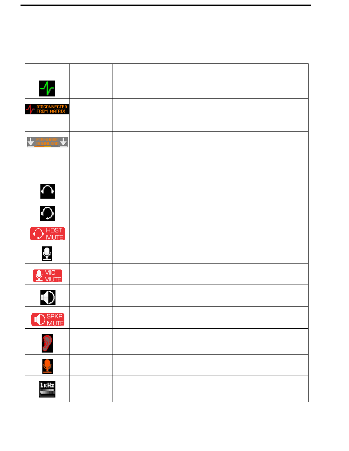
Icon Icon Name Description
Matrix Connected The keypanel is connected to the Matrix. This icon briefly displays at connection.
Disconnected From
Matrix
There is no connection between the Matrix and the keypanel. This icon is displayed as long as
there is no Matrix data connection.
NOTE: When the keypanel is disconnected, it displays its Device Name (for OMNEO) or IP
Address (for RVON) device connections.
Firmware
Download
Firmware is being downloaded to the keypanel. A progress bar at the bottom displays:
chunk progress
overall progress
chunk/overall progress
NOTE: For more information, see “Download Firmware to the KP-3016/3016A From
AZedit” on page 67.
Headphones The headphones are enabled. This indicates the headset microphone is not enabled.
Headset The headset is enabled.
To enable the headset, see “Audio Options Menu, Headset Speaker” on page 98.
Headset Mute The headphone is muted.
If the headset mic is muted, MIC MUTE is shown instead of HDST MUTE
Microphone The microphone is enabled.
Microphone Mute The microphone is muted.
Speaker The speaker is enabled.
Speaker Mute The speaker is muted.
Snoop Tally Active Snoop Tally is Active on the keypanel.
Hot Mic The hot mic is active.
Tone 1kHz Enabled Tone 1kHz is enabled on the keypanel.
Bosch Security Systems, Inc.
To mute the microphone, see “Audio Options Menu, Mic Mute” on page 102.
To mute the headset mic, see “Audio Options Menu, Headset Mic” on page 97
To enable the speaker, see “Audio Options Menu, Speaker” on page 104.
You must have the Hot Mic enabled to use snoop tallies.
To enable snoop tallies, see “Service Menu, Snoop Tally” on page 134.
To activate Hot Mic, see “Audio Options Menu, Matrix Out” on page 101.
To enable tone 1kHz, see “Audio Options Menu, Tone Gen” on page 104.
Technical Manual
F.01U.315.927
Rev. 02
Page 29
KP-3016/KP-3016A Series Basic Operation 31
TABLE 3. Display Icon Descriptions
Icon Icon Name Description
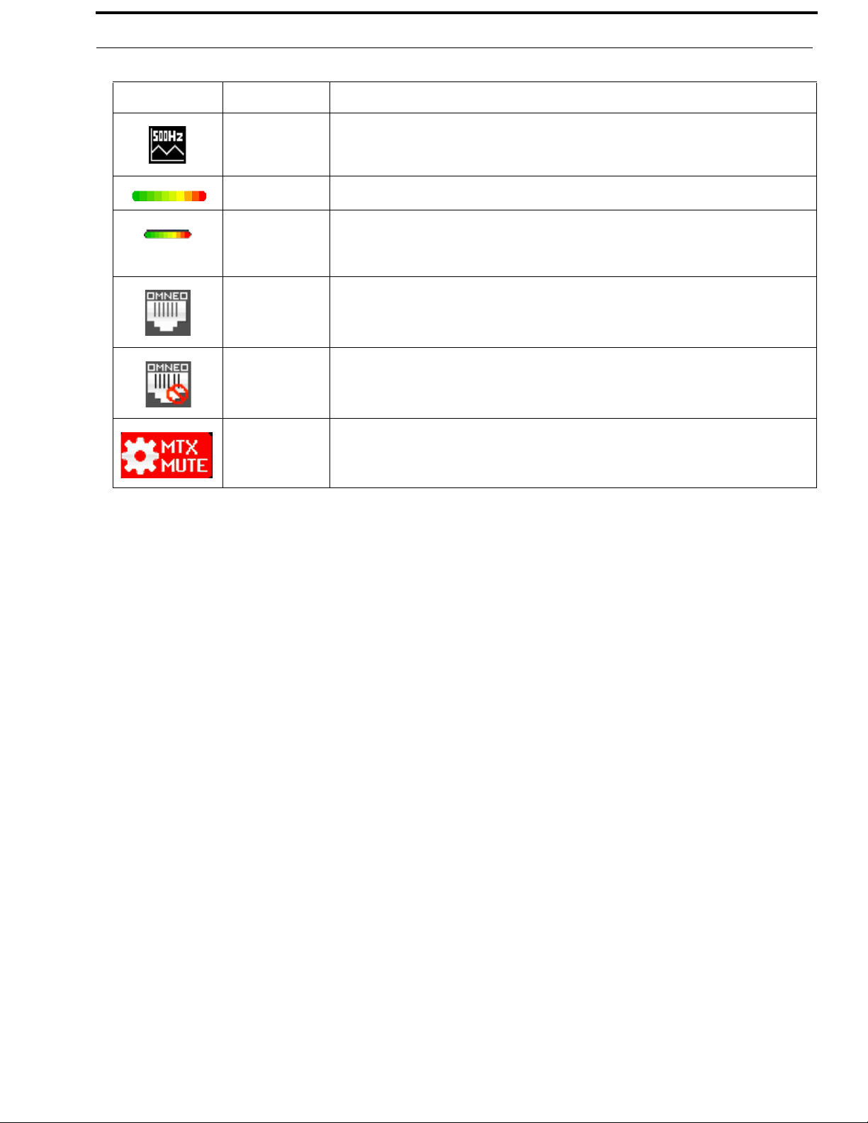
Tone 500Hz
Enabled
Main Volume Bar The main volume bar is used to control the volume for the keypanel inputs and outputs,
Key Volume Bar The key volume bar is used to control the listen gain on a per key level. The listen gain range is
Tone 500Hz is enabled on the keypanel.
To enable tone 500Hz, see “Audio Options Menu, Tone Gen” on page 104.
including all speaker and headset outputs, and matrix inputs.
+6dB to -80db, or Mute.
NOTE: Listen must be assigned on the key assignment for this function to operate.
OMNEO Enabled **This is only applicable for the KP-3016 keypanel.**
The OMNEO matrix interface is enabled on the panel. For more information on OMNEO
Offers, see“Menu System, OMNEO Offers (Only available for KP-3016)” on page 120.
OMNEO Disabled **This is only applicable for the KP-3016 keypanel.**
The OMNEO matrix interface is disabled on the panel. For more information on OMNEO
Offers, see“Menu System, OMNEO Offers (Only available for KP-3016)” on page 120.
Matrix Input Mute
The Matrix Input volume is muted. When the Matrix Input volume is adjusted down to Mute,
the panel displays this flashing icon as a warning that there is no audio from the Matrix.
Bosch Security Systems, Inc.
Technical Manual
F.01U.315.927
Rev. 02
Page 30

32 Basic Operation KP-3016/KP-3016A Series
Keypad Reference View
With both the KP-3016/3016A there are two (2) tiers to each keypanel’s keypad: Primary Mode and SHIFT Mode.
Primary Mode
Primary Mode is used for the most common keypanel functions, such as CLR, SEL, and accessing the Main menu. There are
no special keypad sequences to use these functions.
Shift Mode
SHIFT Mode contains secondary functions used to access more functionality. The SHIFT mode functions are located above
the primary keypad key. The shift functions available; INFO, LEFT/RIGHT, COPY, PAGE, and TYPE.
NOTE: By default, the keypad backlight changes to white when the keypad is in SHIFT mode. For more information, see
“Service Menu, Keypad” on page 125.
To access Shift Mode, do the following:
1. On the keypad, press the SHIFT button.
2. On the keypad, press the key whose SHIFT function you want to access.
NOTE: Once you enter SHIFT mode, you can exit the mode by pressing the SHIFT key again, without pressing any
other keys.
FIGURE 7. KP-3016 Keypad
Keypad
Button
LOC TYPE
Shift
Function
Description
The LOC/TYPE button displays the list of available intercoms (LOCations) available to scroll
from. Select an intercom name to access the scroll lists for that intercom.
The TYPE button displays the keypanel assignment types available for scrolling.
The button moves you backwards through the menu options or available key
assignments one at a time or by the page.
Bosch Security Systems, Inc.
Technical Manual
F.01U.315.927
Rev. 02
Page 31

KP-3016/KP-3016A Series Basic Operation 33
Keypad
Button
MENU INFO
COPY COPY
Shift
Function
Description
The MENU/INFO button is used to access the top level menu structure or access a secondary
menu of commonly used features (see, “INFO button” on page 34).
The MENU button is used to access the top-level menu structure.
> Press the Menu button once.
The top-level menu appears in the panel display.
NOTE: If the keypad backlight is set to On Keypress (Service|Keypad|Backlight|Activation),
you must press the Menu button twice to access the top-level menu.
buttons you can scroll through the list of options available. When a selection is highlighted,
Press the SEL button to navigate down one (1) level in the menu structure.
To access the INFO menu, do the following
1. Press the SHIFT button.
2. Press the MENU/INFO button.
The INFO menu appears in the panel display.
For more details about the INFO button, see “INFO button” on page 34.
The button moves you forward through the menu options or available key assignments
one at a time or by the page.
The COPY button is used to copy an incoming call key assignment from the CWW to a specific
keypanel key.
Using the and
PAGE PAGE
CLR
For example, if caller THRE calls the keypanel, and there is no keypanel key assigned, THRE
appears in the CWW window in the keypanel display. If the keypanel operator wants to assign
the caller (THRE) a key, use the COPY key on the keypad, and then tap the keypanel key where
THRE is to be assigned.
You can also copy from key to key by pressing the COPY+SEL or SHIFT+COPY buttons, and
then tapping the source key and target key.
The PAGE button is used to access a different setup page. You can configure up to 15 pages in
the intercom system. The default number of pages is four (4). To configure the number of pages
available use the Intercom Configuration window, on the Options Page in AZedit.
To enter the graphical page change mode, do the following:
> Press the PAGE+ SEL buttons.
OR
Press the SHIFT+PAG E b u t t o ns.
The CLR button also functions as a back button or a full menu exit. The CLR button is also used
to hide the CWW window.
To clear a menu, do the following:
> Press and hold the CLR button for half a second.
To clear the CWW, do the following:
SHIFT
SEL
Bosch Security Systems, Inc.
> Press the CWW key up to pop entries out of it.
The SHIFT button accesses the secondary keypad actions such as INFO, TYPE, etc.
The SEL button is used to select options highlighted in the menu structure.
Technical Manual
F.01U.315.927
Rev. 02
Page 32

34 Basic Operation KP-3016/KP-3016A Series
INFO button
The INFO button is used to access commonly used features and configuration options for the keypanels. These include the
following:
Feature Description
Panel ID Displays the port number and alpha of the keypanel.
Level 2 Displays the Talk Level 2 key assignments on the keypanel.
Listen Displays the listen key assignments on the keypanel.
Callers Displays a list of current callers to the keypanel.
Assign Types Displays the assignment types of all the configured keypanel keys.
Matrices Displays the Matrix for each key assignment.
Tone Opens the Tone Generator menu. For more information, see “Audio Options Menu, Tone Gen” on
page 104.
Setup Pages Displays the setup pages assigned to each row of keys. You cannot change setup pages from this menu.
Reset Vols Opens the Key Volumes Reset menu. For more information, see “Audio Options Menu, Key Volumes”
on page 100.
Hidden Asgns Displays key assignments assigned to virtual keys (ie, assignments not currently visible).
Test Panels Enables the Test Panel feature. For more information, see “Service Menu, Test Panel” on page 135.
Version Displays the firmware version of the KP-3016/3016A. For more information, see “Display Menu,
Version” on page 108.
To access the Info Menu, do the following:
1. On the keypad, press the SHIFT button.
2. On the keypad, press the INFO MENU button.
The INFO menu appears in the panel display.
NOTE: To exit the INFO menu mode, press the CLR button.
Bosch Security Systems, Inc.
Technical Manual
F.01U.315.927
Rev. 02
Page 33

KP-3016/KP-3016A Series Basic Operation 35
Menu Navigation and Shaft Encoder Knobs
While the keypanel is in menu mode, the Aux Volume shaft encoder (labeled MENU on the KP-3016A keypanel) is used to
move the selection left and right. Or, in the case of a single menu item with up and down control, the shaft encoder is rotated to
scroll through the available selections. This is particularly convenient when setting the keypanel brightness or gain. Also,
pressing the Aux Volume shaft encoder while in menu mode is the equivalent to SEL key operation. Conversely, pressing the
MAIN Volume shaft encoder in menu mode is the equivalent to the CLR key operation.
FIGURE 8. KP-3016 AUX VOL. Knob and KP-3016A MENU Knob
Other navigation options:
• Press and hold the AUX/MENU shaft encoder to exit the menu.
• Double-tap the AUX/MENU shaft encoder to go backwards in the menu.
CLR Button
The CLR button is used either as the BACK function while in MENU mode or to exit MENU mode completely.
To go back one menu level, do the following:
> Press the CLR button once.
To exit the menu, do the following:
> Press and hold the CLR button for half a second
OR
Press the CWW key up.
Bosch Security Systems, Inc.
Technical Manual
F.01U.315.927
Rev. 02
Page 34

36 Basic Operation KP-3016/KP-3016A Series
Basic Intercom Key Operation
IMPORTANT: The KP-3016/3016A series keypanels, as well as the EKP-3016, do not have side to side movement on
the lever keys. You are only able to press up or down. Left and right motions are not available.
To talk on the KP-3016/3016A, do the following:
> Press down on the keypanel key you want to use.
To listen on the KP-3016/3016A, do the following:
> Press up on the keypanel key you want to use.
FIGURE 9. Key Function Position Explanation
Bosch Security Systems, Inc.
Technical Manual
F.01U.315.927
Rev. 02
Page 35

KP-3016/KP-3016A Series Basic Operation 37
Talk/Listen Indicator
The Talk/Listen Indicator, shown in Figure 10, displays a visual indicator when the talk and/or listen key is active. The talk
and listen states of each key are represented by an LED-like horizontal bar at the bottom (talk) and top (listen) of each key.
FIGURE 10. Talk/Listen Indicators
By default, the listen indicator is green and the talk indicator is red. You can change the colors of the indicator by using the
Key Color Window in AZedit. For more information, see “Keypanel Color Window” on page 49.
Crosspoint Gain Adjustment
Crosspoint Gain Adjustment gives you the ability to adjust an individual crosspoint gain associated with different
assignments. For example, you can decrease the gain (audio strength) of key assignment assigned to a person with a strong
(loud) voice.
To adjust the crosspoint gain, do the following:
1. Lift and hold the listen key for which you want to adjust the crosspoint gain.
2. Turn the AUX Vol. (MENU) encoder knob to the right to increase the gain.
OR
Turn the AUX Vol. (MENU) encoder knob to the left to decrease the gain.
The gain is shown on the key.
Bosch Security Systems, Inc.
Technical Manual
F.01U.315.927
Rev. 02
Page 36

38 Basic Operation KP-3016/KP-3016A Series
Keypanel Volume Adjustments
By default, the main volume control adjusts the Output Volume for the speaker or headset, whichever is currently active.
Output volume ranges from +10dB to -48dB and Mute.
To adjust output volume level, do the following:
> On the KP-3016/3016A, turn the MAIN VOLUME encoder to the right to increase the volume for the selected
output.
OR
Turn the MAIN VOLUME encoder to the left to decrease the volume for the selected output.
NOTE: When the MAIN VOLUME encoder is turned, the volume level bar appears in the panel display.
NOTE: You can save the volume adjustments to be power-up defaults using “Menu System, Save Config” on
page 121.
To select a different output volume control, do the following:
> On the KP-3016/3016A, push the MAIN VOLUME encoder once.
The main volume focus switches to the next available output.
Bosch Security Systems, Inc.
Technical Manual
F.01U.315.927
Rev. 02
Page 37

KP-3016/KP-3016A Series Basic Operation 39
Aux Volume Adjustments (KP-3016 Only)
The Aux Volume control knob adjusts the Matrix Input and OMNEO input volumes.
IMPORTANT: If you adjust the Matrix Input volume down to Mute, then the panel displays a flashing Mtx Mute icon
as a warning there is no audio from the Matrix.
Input volume ranges from +10dB to -48dB and Mute.
To adjust input volume level, do the following:
> On the KP-3016/3016A, turn the AUX VOLUME encoder to the right to increase the volume for the selected input.
OR
Turn the AUX VOLUME encoder to the left to decrease the volume for the selected input.
NOTE: When the AUX VOLUME encoder is turned, the volume level bar appears in the panel display.
NOTE:
• You can save the volume adjustments to be power-up defaults using “Menu System, Save Config” on
page 121.
• The inputs appear in the Aux Volume menu if they are enabled and mixed to an output.
IMPORTANT: When OMNEO is present and the keypanel is configured with an AIO connection to the Matrix,
OMNEO 1 can be used as an AUX input. To adjust OMNEO 1 volume, the OMNEO 1 input must be
mixed to an output (any output).
Bosch Security Systems, Inc.
Technical Manual
F.01U.315.927
Rev. 02
Page 38

40 Basic Operation KP-3016/KP-3016A Series
To change the focus of the volume control, do the following:
> On the KP-3016, push the AUX VOLUME encoder once.
The aux volume focus switches to the next available input.
Operation of Intercom Keys with Auto Functions
NOTE: Assignment of keys with auto functions is described in the programming section that follows.
Operation of keys with auto functions, is as follows:
Talk+auto follow Talk and listen can be activated separately. The listen assignment listens to whatever is
assigned to the talk key.
Talk+auto listen Both talk and listen activates when talk is activated.
Talk+auto mute Listen turns off when talk is activated.
Talk+auto reciprocal Listen is always on and talk may be turned on or off.
Talk+auto table If an IFB talk key has an auto table listen assignment, talk and listen is independently
activated. The listen key listens to whatever is defined as the IFB Listen Source for the IFB
assigned to the talk key.
All Call Activating this key activates all keys to the left of it, up to, but not including another all call
key.
Ta lk +D I M If a point-to-point key has the DIM function as a level 2 talk assignment, activating the key
causes the crosspoint levels to diminish for any other intercom ports currently listening to the
same destination and are in the same DIM tables.
Bosch Security Systems, Inc.
Technical Manual
F.01U.315.927
Rev. 02
Page 39

KP-3016/KP-3016A Series Basic Operation 41
Operation of Intercom Keys with Options
Group Option Keys
Activating the master key in a key group activates all keys in the group according to each key’s individual key assignment.
Activating a slave key does not affect any other keys in the group. For more information, see “Key Options Menu, Key
Groups” on page 117.
Solo Key
Activating a key with the solo option causes all other keys to turn off until the solo key is turned off. For more information, see
“Key Options Menu, Solo” on page 118.
Exclusive Key
Activating a key with the exclusive options causes all other Exclusive keys to turn off when activated. Unlike the solo option,
when exclusive is deactivated, the keys turn off and stay off. For more information, see “Key Options Menu, Exclusive” on
page 115.
Lock Key
A key with the lock option on it is locked in the on or off position and cannot be changed until the lock is removed. For more
information, see “Key Options Menu, Lock (Button Lock)” on page 118.
Chime Key
When a chime is configured on a key and a call is received, the chime is activated. You can configure length and type of chime
for the key, as well. For more information, see “Key Options Menu, Chime” on page 114.
Clear Keys
Clearing keys is used to remove any key options assigned to a specific key. For more information, see “Key Options Menu,
Clear” on page 115.
Latching Keys
Latching keys on a keypanel gives the user hands-free operation where keys stay active after quickly tapping the key. For more
information, see “Key Options Menu, Latching” on page 117.
Operation of Intercom Talk Keys with the Speaker DIM Setting
Activating any talk key causes the speaker or headphone volume at the keypanel to diminish by the amount specified in the
DIM menu item on the Service menu. For more information, see “Audio Options Menu, Dim” on page 96.
NOTE: Do not confuse this with the Talk+DIM auto function previously described. Talk+DIM affects the speaker or
headphones on other keypanels when a particular talk key is activated on the keypanel. Speaker DIM affects the
speaker or headphone level on the keypanel when any talk key on the keypanel is activated.
Bosch Security Systems, Inc.
Technical Manual
F.01U.315.927
Rev. 02
Page 40

42 Basic Operation KP-3016/KP-3016A Series
Call Waiting Operation
Occasionally, a keypanel may call and there is not a key assigned to talk back to the caller. In this case, the caller’s name
appears in the CWW (Call Waiting Window).
NOTE: The KP-3016/3016A keypanels support a graphical call waiting window. For more information, see “Graphical
Call Waiting Window Operation” on page 44.
To answer a CWW call, do the following:
> Press down and hold the CWW key to talk back.
To clear a name from the CWW window, do the following:
> When the CWW window is populated, tap up on the CWW key.
NOTE: If a second call is received in the CWW while a caller name is already displayed, the Call Waiting window
flashes.
To answer a second call, do the following:
> Ta p th e CWW key up to clear the first name, and then hold the CWW key down to talk to the second caller.
NOTE: By default, only the names of callers who are not currently assigned to intercom keys appear in the call
waiting window. Alternately, you can force all caller names to display in the call waiting window. This is
controlled by DIP Switch 2 on the ADAM Master Controller card or the Always stack callers in the call
waiting window option found in AZedit (Options|Intercom Configuration|Options). Setting this option in
AZedit overrides the DIP Switch 2 setting on the Master Controller.
Bosch Security Systems, Inc.
Technical Manual
F.01U.315.927
Rev. 02
Page 41

KP-3016/KP-3016A Series Basic Operation 43
Graphical Call Waiting Window
Traditionally, incoming calls have been displayed on key 16 on the keypanel, flashing to indicate an incoming call. The
KP-3016/3016A Series keypanel can keep a history of the last nine (9) callers and display them in a scrollable, graphical
window above keys 15 and 16. The CWW displays three (3) calls at a time (only two in Unicode) with a scroll arrow
appearing if there are more than three (3) calls in the list.
FIGURE 11. Graphical Call Waiting Window
TABLE 4. Graphical CWW Call Description
Item Description
New Call White background
Selected Call / Not Talking Cyan background
Selected Call / Talking Green background
Old Call Gray background
Bosch Security Systems, Inc.
Technical Manual
F.01U.315.927
Rev. 02
Page 42

44 Basic Operation KP-3016/KP-3016A Series
Graphical Call Waiting Window Operation
Use Table 4 on page 43 and Figure 11 on page 43 to understand the different states of the CWW.
Display or Hide the CWW
To display the CWW, do the following:
> On the KP-3016/3016A panel, lift up on the CWW key.
The graphical call waiting window appears.
To hide the CWW, do the following:
> Press the CLR button.
The CWW closes.
NOTE: If the CWW list is visible and not empty, it remains visible until hidden. If the CWW list is visible, but
empty, it auto-hides after a five-second timeout.
Incoming Calls
When a call is received at the KP-3016/3016A panel, the graphical CWW list appears on the keypanel display. Unlike the
keypanel talley indicators in previous keypanel versions:
• the graphical CWW list appears on the keypanel display.
• the graphical CWW and the call flashes (tallies), rather than the CWW button.
Up to nine (9) calls can be stored in the CWW history scroll list. The most recent call is inserted at the top of the graphical
CWW list (position 1) with a white background (See Figure 11 on page 43). Other items in the CWW list are shifted down, as
necessary. The ninth call in the list is dropped when a new call is received.
FIGURE 12. Graphical Call Waiting Window Highlighted Call
NOTE: A highlighted item in the graphical CWW cannot be shifted off the CWW list.
To scroll the CWW list, do the following:
> When the CWW list is visible, use the arrow buttons to scroll through the list.
The highlight moves through the scroll list.
Bosch Security Systems, Inc.
Technical Manual
F.01U.315.927
Rev. 02
Page 43

KP-3016/KP-3016A Series Basic Operation 45
To answer a call on the graphical CWW, do the following:
1. Scroll the CWW to highlight the call you want to answer.
The highlighted call is shown with a cyan background.
2. Press down and hold the CWW key to talk to the caller.
The highlight in the CWW list turns green and moves to the top of the list when talking with the caller.
3. Release the CWW key to stop talking.
The call is ended. The background of the caller in the CWW list turns a light gray (if not highlighted).
Clearing the CWW List
To clear the CWW list, do the following:
1. If the CWW is not visible, press the CWW key to make it visible and the call selected.
2. Use the button keys to scroll to the call you want to remove.
3. Press the CWW key up, to clear the selected entry.
4. Repeat steps 2 & 3, as necessary.
Bosch Security Systems, Inc.
Technical Manual
F.01U.315.927
Rev. 02
Page 44

46 Basic Operation KP-3016/KP-3016A Series
Mic Select
The mic (input) or speaker/headset (output) can be configured as Always On or Enabled, or Disabled.
For more information, see:
• “Audio Options Menu, Headset Speaker” on page 99.
• “Audio Options Menu, Panel Mic” on page 105.
• “Audio Options Menu, Headset Mic” on page 98.
TABL E 5 . Source Configuration Matrix and Display icons
ALWAYS ON/ENABLED SWITCHED DISABLED ICON DISPLAYED
Panel Mic
XX
Headset Mic
Speaker
Headset
X
XX
X
XX
X
XX
X
No icons display on the keypanel.
No icons display on the keypanel.
No icons display on the keypanel.
No icons display on the keypanel.
Bosch Security Systems, Inc.
Technical Manual
F.01U.315.927
Rev. 02
Page 45

KP-3016/KP-3016A Series Basic Operation 47
Setup Pages
Setup Pages are used to provide access to more key assignments than a panel has keys, enabling the user to quick switch one
set of assignments for another.
You can have up to 15 Setup Pages per keypanel port.
By default, four (4) Pages are configured.
NOTE: To change the number of Pages available for ports, in AZedit go to Options|Intercom Configuration|Options tab
in AZedit. Change the Setup pages per port field to the number of pages needed. This causes the intercom to
resize (first birthday), meaning the intercom configurations are erased.
To open Setup Pages, do the following:
> On the keypanel keypad, press the PAGE key.
OR
On the keypanel keypad, press the SHIFT +PAGE keys.
The graphical page mode appears in the keypanel display screen. The page tab displays turquoise.
IMPORTANT: To add key assignments to the setup pages, see “Menu System, Key Assign Menu” on page 109.
To toggle between the Setup pages, do the following:
1. Use the left and right arrow keys to change the page.
When changing the page, the Page tab appears yellow, until selected.
2. Press the SEL key to select the page.
The Page tab returns to the turquoise color.After two (2) seconds with no SEL button selection, the page is
automatically selected.
NOTE: Use SHIFT+Left/Right to switch between the Main and EKP page, when an EKP is attached.
Bosch Security Systems, Inc.
Technical Manual
F.01U.315.927
Rev. 02
Page 46

48 Basic Operation KP-3016/KP-3016A Series
Menu Passwords
As with other keypanels, the KP-3016/3016A allows you to lock the entire menu structure or only the service menu. This is
implemented through AZedit (System|Miscellaneous|Keypanel Menu Password). For more information, see the AZedit user
manual (p/n F01U239453).
NOTE: Passwords can only include the digits 0-9.
Because the KP-3016/3016A does not have digit keys, passwords are entered by rotating the AUX/MENU shaft encoder to
select a digit.
To enter a menu password, do the following:
1. Press the MENU button.
Password? appears in the keypanel display screen.
2. Rotate the AUX/MENU shaft encoder to the first digit of the password.
3. Press the SEL key.
OR
Tap the AUX/MENU shaft encoder.
OR
Use the left or right arrow keys to move to the next digit.
The cursor moves to the next digit.
4. Repeat steps 2 and 3 until the entire password is entered.
5. Press SEL when the password is completely entered.
If the password is entered correctly, the menu appears.
NOTE:
• Use the CLR button, double-click the AUX/MENU shaft encoder, or single-click the MAIN shaft
encoder to erase the last digit.
• If there are no digits, the CLR button or double-click either the AUX/MENU or MAIN shaft encoder to
exit the menu.
Bosch Security Systems, Inc.
Technical Manual
F.01U.315.927
Rev. 02
Page 47

KP-3016/KP-3016A Series Basic Operation 49
Keypanel Color Window
The Keypanel Color window, shown in Figure 13, is used to change the text and background colors assigned to function
types, key assignments, and talk/listen indications. You can modify local intercom key assignments and function type colors,
as well as remote intercom function type colors, giving you the flexibility to distinguish different systems through the use of
color patterns.
The Keypanel Color window is only available when the following requirements are met:
• running AZedit version 3.7.0 or later.
• running MCII-e version 2.1.0 or later.
NOTE: Key colors are associated with assignments and assignment types, not the physical keys they are assigned to.
FIGURE 13. Keypanel Colors Window
Bosch Security Systems, Inc.
Technical Manual
F.01U.315.927
Rev. 02
Page 48

50 Basic Operation KP-3016/KP-3016A Series
Function Types Page
The Function Types page, shown in Figure 13, is used to change the default colors assigned to the various keypanel function
types.
Select Intercom Drop Down Menu
The Select Intercom drop down menu is used to select the intercom system (local or remote) in which you want to change the
color of the key function types.
Recent Colors Group Box
The Recent Colors group box displays the 18 most recently used colors.
Current Color Group Box
The Current Color group box displays the currently selected color (current color cell), whether from the color palette or
recent colors. Also, using the Hue, Sat, Lum, Red, Green, and/or Blue spin boxes, you can adjust the selected color to create a
unique color for the function type.
NOTE: You can drag and drop colors from the color picker or recent color check boxes, and drop it on the background or
text area of one (1) of the cells in the Color Grid (Figure 14 on page 51). You can also select a color in the Color
Grid and drop and drag it to the Current Color Cell field. By holding down the Ctrl key on the keyboard, you can
select multiple cells in the Color Grid, thus allowing you to apply color to multiple key assignments.
Apply To Background Button
The Apply to Background button is used to apply the color selection to the background.
Default Background Button
The Default Background button is used to reset the background color to the default color.
Apply To Text Button
The Apply to Text button is used to apply the color selection to the text of the type of assignment.
Default Text Button
The Default Text button is used to reset the text color to the default color of the type of assignment.
Bosch Security Systems, Inc.
Technical Manual
F.01U.315.927
Rev. 02
Page 49

KP-3016/KP-3016A Series Basic Operation 51
Color Grid
FIGURE 14. Color Grid
Function Type Column
The Function Type column displays the different function types you can make key color changes for.
Available selections are: Null, Special Functions, Ports, Party Lines, IFBs, Special Lists, GPI Outputs, ISOs, UPL Resources,
and IFB Special Lists.
Color Column
The Color column displays the current text and background colors assigned to the function type.
NOTE: You must select the current color box next to the function type you want to change the color for. When selected,
a thick black line appears around the box.
Only Show Non-Default Background Colors Check Box
The Only Show Non-Default Background Colors check box, if selected, shows colors only for function types set to a color
other than their default color.
Bosch Security Systems, Inc.
Technical Manual
F.01U.315.927
Rev. 02
Page 50

52 Basic Operation KP-3016/KP-3016A Series
Key Assignment Page
The Key Assignment page, shown in Figure 15, is used to change the colors assigned to the various assignment types. This
means you can assign different colors to the individual function type resources. For example, you can change the display color
for the party line assignment number 003.
FIGURE 15. Key Assignments Page
Select Function Type Drop Down Menu
The Select Function Type drop down menu is used to select the function type you want to display the function number
resources for.
Available selections for this field are: Ports, Party Lines, IFBs, Special Lists, GPI Outputs, ISOs, UPL Resources, and IFB
Special Lists.
Bosch Security Systems, Inc.
Technical Manual
F.01U.315.927
Rev. 02
Page 51

KP-3016/KP-3016A Series Basic Operation 53
Function Number Column
The Function Number column displays the function numbers (resources available) you can modify the color of the assigned
key for.
NOTE: Key colors are associated with assignment types, not the keys they are assigned to.
Color Column
The Color column displays the current color assigned to the function number.
NOTE: You must select the current color box next to the function number you want to change the color for. When
selected, a thick black line appears around the box indicating it is selected.
Assignment Groups Page
The Assignment Groups page, shown in Figure 16, is used to change colors of the members of the different assignment
groups.
FIGURE 16. Assignments Groups Page
Bosch Security Systems, Inc.
Technical Manual
F.01U.315.927
Rev. 02
Page 52

54 Basic Operation KP-3016/KP-3016A Series
Select Assignment Group Drop Down Menu
The Select Assignment Group drop down menu is used to select the assignment group whose members you want to modify
the key colors for.
Intercom Column
The Intercom column displays the name of the intercom where the group resides.
Function Type Column
The Function Type column displays the type function assigned to the group.
Function Number Column
The Function Number column displays the number of the assignment group you select from the Assignment Group drop
down menu. For more information, see “Select Assignment Group Drop Down Menu” on page 54.
Color Column
The Color column is used to select the assignment group member you want to modify the associated color with.
To select the color column, do the following:
> Click the color box next to the assignment group member.
A thick, black outline appears around the selected color box.
Bosch Security Systems, Inc.
Technical Manual
F.01U.315.927
Rev. 02
Page 53

KP-3016/KP-3016A Series Basic Operation 55
Miscellaneous Colors Page
The Miscellaneous Colors page, shown in Figure 17, is used to change the colors of the talk and listen indicators seen on the
KP-3016/3016A series keypanel when talk and/or listen is activated.
For more information on Talk and Listen indicators, “Talk/Listen Indicator” on page 37.
FIGURE 17. Miscellaneous Colors Page
Bosch Security Systems, Inc.
Technical Manual
F.01U.315.927
Rev. 02
Page 54

56 Basic Operation KP-3016/KP-3016A Series
Enhanced Tallies
Enhanced Tallies allow you to configure, using AZedit, how tallies look on the keypanel. You are able to change how
incoming calls, PLs, IFBs, etc look on the keypanel. By default, an incoming call tally is indicated by a flashing alpha. With
enhanced tallies, you can configure the text and background colors used to display the key in both flashing and normal states
for the duration of the tally. You can also configure a chime to be played when an incoming call is received, as well as an icon
to appear announcing the call. For more information, see Table 8, “Tally Icon Descriptions,” on page 63.
Requirements
AZedit version 5.0.0 or later
MCII-e version 3.2.0 or later
To open the Enhanced Tallies window, do the following:
1. Open AZedit.
2. From the menu bar, select System|Miscellaneous|Enhanced Tallies.
The Enhanced Tallies window appears.
TABLE 6. Enhanced Tallies Window
Bosch Security Systems, Inc.
Technical Manual
F.01U.315.927
Rev. 02
Page 55

KP-3016/KP-3016A Series Basic Operation 57
Tally # Column
The Tally # column displays the tally number. This number is associated with the tally description and is used in selecting
tallies to generate via UPL statements. AZedit supports 20 different tallies, however, the first 10 are predefined.
TABL E 7 . Predefined Tallies
Tally # Description
1 Incoming Call
2 Extend Call
3Trunk in Use
4Trunk Busy
5IFB in Use
6IFB Busy
7PL in Use
8 General In Use
9 TIF Off-Hook
10 TIF Ringing
Mode Column
The Mode column is used to select the type of tally to use.
There are three (3) options available:
No Tally
Flash Text Flashes text for a user-determined (duration column) amount of time.
Flash Icon Shows an icon for a user determined (duration column) amount of time. For more information, see
Table 8, “Tally Icon Descriptions,” on page 63.
Description Column
The Description column is used to enter a description of the tally you create.
IMPORTANT: It is recommended you do not change the pre-defined tallies descriptions. Changing the description does
not change pre-defined purpose of the tally. For example, if you change the description for IFB Busy to
Trunk Busy, it still activates when an IFB is busy and may be confusing to users.
To change the Description column, do the following:
1. In the Description column, double-click the tally description you want to change.
The selected Description cell becomes active.
2. In the cell, enter the tally description you want.
Duration Column
The Duration column is used to select the duration the tally is activated for.
Available options for this field are: Indefinite and one (1) second through five (5) minutes.
To set the tally duration, do the following:
1. In the Duration column, select the duration of the tally you want to change.
A drop down menu appears.
2. From the drop down menu, select the desired duration.
Bosch Security Systems, Inc.
Technical Manual
F.01U.315.927
Rev. 02
Page 56

58 Basic Operation KP-3016/KP-3016A Series
Characteristics Column
The Characteristics column is used to configure the characteristics or behavior of the visual tally. Depending on what you
select in the Mode column determines what is seen in this column. From the Characteristics column, you can access a
configuration window for either Text or Icon selections. If No Tally is selected in the Mode column, the Characteristics
column is blank.
To open the Text configuration window, do the following:
1. In the Characteristics column, click on the cell with the word Text.
The cell animates the tally as defined (for example, flashing text with color or animating icons) and an ellipsis button
appears in the cell.
2. Click the Ellipsis button.
The Flash Text Characteristics window appears. For more information, see “Flash Text Characteristics Window” on
page 60.
To open the Icon configuration window, do the following:
1. In the Characteristics column, click on the cell with word Icon.
An ellipsis button appears in the cell next to the word Icon.
2. Click the Ellipsis button.
The Show Icon Characteristics window appears. For more information, see “Show Icon Characteristics Window” on
page 62.
Chime # Column
The Chime # column is used to select the type of chime to play when a tally is activated.
Available options for this field are: System Chime #1, System Chime #2, System Chime #3, and System Chime #4.
To set the chime, do the following:
1. In the Chime # column, select the chime cell you want to change.
A drop down menu appears.
2. From the drop down menu, select the desired chime.
Duration Column
The Duration column is used to select the length of time to for the chime to last.
Available options for this field are: One-shot and one (1) second through five (5) minutes.
To set the duration of the chime, do the following:
1. In the Duration column, select the duration of the tally you want to change.
A drop down menu appears.
2. From the drop down menu, select the desired duration.
Bosch Security Systems, Inc.
Technical Manual
F.01U.315.927
Rev. 02
Page 57

KP-3016/KP-3016A Series Basic Operation 59
Legacy Action Column
The Legacy Action column is used to select how the tally descriptions is implemented on keypanels that do not support
Enhanced Tallies.
Available options are:
No Tally
Incoming Call Tally
In-Use Tally
Busy Tally
To select a legacy action, do the following:
1. Click in the Legacy Action column cell desired.
A drop down arrow appears.
2. From the Legacy Action drop down menu, select desired action.
Bosch Security Systems, Inc.
Technical Manual
F.01U.315.927
Rev. 02
Page 58

60 Basic Operation KP-3016/KP-3016A Series
Flash Text Characteristics Window
The Flash Text Characteristics window is used to configure the way a text tally behaves for the selected tally.
FIGURE 18. Flash Text Characteristics Window
Swap Foreground / Background Colors Check Box
The Swap Foreground / Background Colors check box indicates the foreground color swaps with the background color
creating a blinking effect on the keypanel display.
Flash State Group Box
The Flash State group box is used to assign text and background colors used when a tally state is flashing.
Enable Text Color Check Box
The Enable Text Color check box enables the Selected Color cell and Browse button. This means you can modify the color of
the Text displayed.
Selected Color Cell and Ellipsis Button
The Selected Color cell displays the currently selected color of the text.
The Ellipsis button opens the Select Color window where you can assign a different color to the text.
Enable Background Color Check Box
The Enable Background Color check box enables the Selected Color cell and Browse button. This means you can modify the
color of the Background displayed.
Bosch Security Systems, Inc.
Technical Manual
F.01U.315.927
Rev. 02
Page 59

KP-3016/KP-3016A Series Basic Operation 61
Selected Color Cell and Ellipsis Button
The Selected Color cell displays the currently selected color of the background.
The Ellipsis button opens the Select Color window where you can assign a different color to the background.
Normal State Group Box
The Normal State group box is used when the tally is active and is not in the flash state. If there is no tally active, then the
colors are whatever is defined for the assignment in the intercom.
Enable Text Color Check Box
The Enable Text Color check box enables the Selected Color cell and Browse button. This means you can modify the color of
the Text displayed.
Selected Color Cell and Ellipsis Button
The Selected Color cell displays the currently selected color of the text.
The Ellipsis button opens the Select Color window where you can assign a different color to the text.
Enable Background Color Check Box
The Enable Background Color check box enables the Selected Color cell and Browse button. This means you can modify the
color of the Background displayed.
Selected Color Cell and Ellipsis Button
The Selected Color cell displays the currently selected color of the background.
The Ellipsis button opens the Select Color window where you can assign a different color to the background.
Enable Alternate Text Check Box and Entry Field
The Enable Alternate Text check box and entry field is used to enter alternate text or characters that appears intermittently
with the existing tally text.
This field can contain up to four (4) characters.
Duty Cycle Drop Down Menu
The Duty Cycle drop down menu is used to select the rate the tally flashes alternate with normal text mode. The flash period is
one (1) second.
Available options for this menu are:
On Solid There is no flash
Slow 25% The flash appears for 25% of the flash period (1/4 of a second), while the normal mode appears
for 75% of the flash period (3/4 of a second)
Slow 50% The flash and the normal mode appear for 50% of the flash period (1/2 second each)
Fast 50% The flash and the normal appear for 50% of the flash period in alternating pattern (1/4 second
flash, 1/4 second normal mode, 1/4 second flash, and 1/4 second normal mode)
Fast 75% The flash appears for 75% (3/4 of a second), while the existing text appears for 25% (1/4 if a
second) of the flash period
Bosch Security Systems, Inc.
Technical Manual
F.01U.315.927
Rev. 02
Page 60

62 Basic Operation KP-3016/KP-3016A Series
OK Button
The OK button is used to accept/apply the changes and close the window.
Cancel Button
The Cancel button is used to reject the changes and close the window.
Show Icon Characteristics Window
The Show Icon Characteristics window is used to configure which icon to display during a tally event and the rate at which
it flashes during the event.
FIGURE 19. Show Icon Characteristic Window
Icon Drop Down Menu
The Icon drop down menu is used to select the icon you desire. See “Tally Icon Descriptions” on page 63
Duty Cycle Drop Down Menu
The Duty Cycle drop down menu is used to select the rate the icon flashes. The flash period is 1 second.
Available options for this menu are:
On Solid There is no flash
Slow 25% The icon appears for 25% of the slow flash period
Slow 50% The icon appears for 50% of the slow flash period
Fast 50% The icon appears for 50% of the fast flash period in alternating 25% segments
Slow 75% The icon appears for 75% of the fast flash period
Animate 4-frame animation, each frame displays for 25% of the flash period.
OK Button
The OK button is used to accept/apply the changes and close the window.
Cancel Button
The Cancel button is used to reject the changes and close the window.
Bosch Security Systems, Inc.
Technical Manual
F.01U.315.927
Rev. 02
Page 61

KP-3016/KP-3016A Series Basic Operation 63
Enhanced Tally Icons
Enhanced Tally Icons, shown in Table 8, are used to visually
alert keypanel users of different events occurring on the
keypanel and in the Matrix system. The keypanel ships with
these icons built-in by default. However, you can download
new icons to the panel using AZedit.
NOTE: These icons are the default icons included with
the keypanel. These icons can be used for any
purpose. Not all the icons are used as
defaults.The descriptions in Table 8 are just
suggested uses.
TABLE 8. Tally Icon Descriptions
Icon Icon Name Description
Target Incoming Call (animation supported) – A
call is coming into the keypanel and the
animation toggles the target every half
second.
Extended Call (animation not supported)–
The extended call tally is generated when
the key is on for a predetermined amount
of time. In English intercoms, five (5)
seconds pass before the tally begins, while
in Japanese intercoms, two (2) seconds
must pass
Red Star Trunk In-Use (animation not supported)
Trunk Busy (animation supported) – The
trunk is busy. The animation toggles the
star on/off every quarter of a second.
Black Star IFB/ISO In Use (animation not supported)
IFB/ISO Busy (animated) - The IFB/ISO is
busy. The animation rotates the star.
Orange Wave PL In-Use (animation not supported)
Gray Gear General In-Use (animation not supported)
- Used in Japanese intercoms. This tally is
used to show when other keypanels are
doing an action on the keypanel. In a
Japanese intercom, if your panel is in-use
(i.e., you turn on a talk key to anybody),
and I have your assignment on my
keypanel, the assignment on my keypanel
displays the General In-Use tally, even
though we are not talking to each other.
Red Phone TIF Ringing (animation supported) - The
handset vibrates in the animation.
TABL E 8 . Tally Icon Descriptions
Icon Icon Name Description
Question Available for UPL Tally (animation
supported) - The animation flashes the
icon on and off every half second.
Flag Available for UPL Tally (animation
supported) - The animation flashes the
icon on and off every half second.
Person Available for UPL Tally (animation
supported) - The animation flashes the
icon on and off every half second.
Link Available for UPL Tally (animation
supported) - The animation flashes the
icon on and off every half second.
Car Available for UPL Tally (animation
supported) - The animation flashes the
icon on and off every half second.
Lightening
Bolt
House Available for UPL Tally (animation
Handset Available for UPL Tally (animation
Lock Available for UPL Tally (animation not
Speaker Available for UPL Tally (animation
Play Available for UPL Tally (animation
Message Available for UPL Tally (animation
Available for UPL Tally (animation
supported) - The animation flashes the
icon on and off every half second.
supported) - The animation flashes the
icon on and off every half second.
supported) - The animation flashes the
icon on and off every half second.
supported)
supported) - The animation flashes the
icon on and off every half second.
supported) - The animation flashes the
icon on and off every half second.
supported) - The animation flashes the
icon on and off every half second.
Yellow Phone TIF Offhook (animation supported) - The
TIF key is active. The animation flashes
the icon on and off every half second.
Exclamation Available for UPL Tally (animation
supported) - The animation flashes the
icon on and off every half second.
Heart Available for UPL Tally (animation
supported) - The animation flashes the
icon on and off every half second.
Bosch Security Systems, Inc.
Technical Manual
Red Circle Available for UPL Tally (animation
supported) - The animation flashes the
icon on and off every half second.
F.01U.315.927
Rev. 02
Page 62

64 Basic Operation KP-3016/KP-3016A Series
Tally (Key Overlays)
To create your own tally icons (key icons), the icons are 16x16 pixels. 32 key icons are supported, as well as 4-frame
animation, so the bitmap must be 512x64, producing a table of 32x4 icons (each icon 16x16 pixels), see Figure 20. AZedit
accepts a narrower image (as long as it is a multiple of 16) and uses white space to fill in the missing pixels. Shorter images are
supported (as long as the image is either 16 or 32 pixels tall) and is replicated (3 times, or once) to get an image measuring 64
pixels tall.
FIGURE 20. Tally (key) icon 512x64 pixel bitmap of key icons
Panel Tally
Panel Tally is used to notify a keypanel user of an event not specifically belonging to a key; for example, a blinking icon
appears when a newscast is on air. Panel tallies are controlled through the use of UPL statements. Multiple UPL statements
can be configured, but only one (1) icon displays at a time. Lower numbered icons take priority.
NOTE: The keypanel ships with these icons built-in by default. However, you can download new icons to the panel using
AZedit.
Available panel tally icons are:
Suggested Use
Alarm, Appointment, Event Positive, Notify
Alarm, Chime, Notify Favorite
Target, Incoming Information
Appointment, Event Negative
On-Air, Live On Air
Error Warning, Alarm, Alert
Warni ng
Bosch Security Systems, Inc.
Technical Manual
F.01U.315.927
Rev. 02
Page 63

KP-3016/KP-3016A Series Basic Operation 65
Panel Icons
For panel icons, the icons are 32x32 pixels. 16 panel icons are supported, as well as 4-frame animation, so the bitmap must be
512x128, producing a table of 16x4 icons (each icon 32x32 pixels), see Figure 21. Like key icons, AZedit accepts a narrower
image (as long as it is a multiple of 32) and uses white space to fill in the missing pixels. Shorter images are supported (as long
as the image is either 32 or 64 pixels tall) and replicates (3 times, or once) to get an image measuring 128 pixels tall.
FIGURE 21. 512 x128 pixel bitmap of panel icons
Bosch Security Systems, Inc.
Technical Manual
F.01U.315.927
Rev. 02
Page 64

66 Basic Operation KP-3016/KP-3016A Series
Bosch Security Systems, Inc.
Technical Manual
F.01U.315.927
Rev. 02
Page 65

CHAPTER 4
Firmware Download
Download Firmware to the KP-3016/3016A From AZedit
IMPORTANT: When downloading firmware using AZedit, the file type used is a .mot file.When downloading
firmware using the Firmware Upload Tool, the file type is a .capfw file.
To download firmware to the keypanel, do the following:
1. Open AZedit.
2. From the Status menu, select Port.
The Port Status window appears.
3. Find the port number where the KP-3016/3016A is connected.
Bosch Security Systems, Inc.
Technical Manual
F.01U.315.927
Rev. 02
Page 66

68 Firmware Download KP-3016/KP-3016A Series
4. Highlight the Port (keypanel) to be updated.
You may select more than one (1) at a time by holding CTRL key down while you select.
5. Right-click the highlighted selections.
A popup menu appears.
6. Select Download firmware....
The Firmware Download window appears.
7. Using the browse button, browse to the file to be downloaded.
8. Click Open.
The Download Device Firmware window appears.
9. Click Begin Download.
The download begins.
10. Click OK.
The KP-3016/3016A firmware download finishes.
11. Verify the keypanel displays the Processing Download icon with progression bar.
Bosch Security Systems, Inc.
Technical Manual
F.01U.315.927
Rev. 02
Page 67

KP-3016/KP-3016A Series Firmware Download 69
NOTE:
• This can take up to 2 minutes to complete if connected via OMNEO and up to 15 minutes to complete if
connected via AIO. Use the Keypanel Version Information window to follow the progress of the
download. Also, the keypanel displays Firmware Download on the panel display until the download is
complete.
• The KP-3016/3016A resets itself once the firmware download is complete and the flash reprogrammed.
• While the firmware is downloading, chunk progress is displayed by incremental blocks. Also, the
keypanel displays an icon warning not to turn off the panel while the flash is being reprogrammed.
12. In the Keypanel Version Information window, verify the version upgrade.
Download Firmware to the Keypanel Using the Firmware Upload Tool
Required Firmware version:
FWUT V3.0.3 or later
IMPORTANT: When downloading firmware using AZeidt , the file type used is a .mot file.When downloading
firmware using the Firmware Upload Tool, the file type is a .capfw file.
To download firmware to the keypanel, do the following:
1. Open the Firmware Upload Tool.
Bosch Security Systems, Inc.
Technical Manual
F.01U.315.927
Rev. 02
Page 68

70 Firmware Download KP-3016/KP-3016A Series
2. From the File menu, select Options.
The Firmware Upload Tool Options window appears.
3. Click the Change button.
The folder network window appears.
4. Navigate to the folder where the firmware resides.
5. Click OK.
6. Click OK, again.
The Firmware Upload Tool Options window closes.
7. From the OKP Device page, select the device you want to update.
8. Click the Upload button.
The Select Firmware for Upload window appears.
Bosch Security Systems, Inc.
Technical Manual
F.01U.315.927
Rev. 02
Page 69

KP-3016/KP-3016A Series Firmware Download 71
9. From the list of firmware, select the firmware you want to download.
10. Click the Start button.
11. Once the firmware has been updated, the keypanel reboots automatically.
Bosch Security Systems, Inc.
Technical Manual
F.01U.315.927
Rev. 02
Page 70

72 Firmware Download KP-3016/KP-3016A Series
Download Firmware Using the Bootloader
The Bootloader is used to upload a new bootloader image or to upgrade the keypanel firmware if it is corrupt or fails in such
a way that makes normal downloading of new firmware impossible.
IMPORTANT: If the keypanel firmware is corrupt, the panel may boot automatically into the bootloader. However, if
the keypanel firmware appears valid, but fails to run properly, you may need to force the keypanel into
the bootloader to load new keypanel firmware. You can also force the keypanel into the bootloader in
order to download a new bootloader image (though this can also be done through the keypanel
firmware, see “Enable Downloading New Bootloader from the Keypanel” on page 74.
Run the Bootloader
To run the bootloader, do the following:
1. Power off the keypanel.
2. Verify the KP-3016/3016A is powered off, but still connected to the FRAME.
3. At the same time, press and hold keypanel key 15 in the listen position (up) and keypanel key 16 in the talk
position (down), while you connect the power cord to the keypanel.
KP-3016/3016A - Boot Loader Waiting for download... appears in the panel display.
4. In AZedit, from the Status menu, select Software Versions.
The Software Versions popup menu appears.
5. From the Software Versions popup menu, select Keypanels.
The Keypanel Version Information window appears.
Bosch Security Systems, Inc.
Technical Manual
F.01U.315.927
Rev. 02
Page 71

KP-3016/KP-3016A Series Firmware Download 73
6. From the Keypanel Version Information window, find and select the specified KP-3016/3016A.
7. Right-click on the KP-3016/3016A.
A popup menu appears.
8. From the popup menu, select Download Firmware....
The Firmware Download navigation window appears.
9. Navigate to and select your firmware file (i.e., KP-Series_client_z.mot).
10. Click Open.
The Download Device Firmware window appears.
11. Click Begin Download.
The Download begins and a popup message appears.
12. Click OK.
The KP-3016/3016A firmware download finishes.
NOTE: This can take up to 15 minutes to complete if connected via AIO. Use the Keypanel Version Information window
to follow the progress of the download (the number and percentage of chunks completed). Also, the firmware
progression is displayed on the KP-3016 panel display until the download is complete.
NOTE: Once the Boot Loader is finished downloading, it reprograms the flash and reboots itself.
Bosch Security Systems, Inc.
Technical Manual
F.01U.315.927
Rev. 02
Page 72

74 Firmware Download KP-3016/KP-3016A Series
Enable Downloading New Bootloader from the Keypanel
Once you have enabled the keypanel to allow the firmware to be downloaded to it, you can use AZedit to configure the
keypanel.
To enable bootloader firmware downloads on the keypanel, do the following:
1. While pressing the Main Vol and Aux Vol encoders on the front of the keypanel at the same time, press the MENU
button.
The main menu appears in the panel display.
2. Using the AUX/MENU shaft encoder, select Service.
3. Press the SEL button.
The Service menu options appear in the panel display.
4. Using the AUX/MENU shaft encoder, select Boot Code.
5. Press the SEL button.
Allow Download and Version X.X.X (where X represents version numbers) appears in the panel display.
6. Using the AUX/MENU shaft encoder, select Allow Download.
7. Press the SEL button.
The keypanel now allows firmware downloads.
If the keypanel is powered off or loses power, the state of the Allow Download option resets to not enabled. You must
reconfigure the option for it to allow new bootloader firmware to be downloaded.
Display the FPGA Version
To display the FPGA version currently installed in the keypanel, do the following:
1. While pressing the Main Vol and Aux Vol/MENU encoders on the front of the keypanel at the same time, press the
MENU button.
The main menu appears in the panel display.
2. Using the AUX/MENU shaft encoder, select Service.
3. Press the SEL button.
The Service menu options appear in the panel display.
4. Using the AUX/MENU shaft encoder, select FPGA Version.
5. Press the SEL button.
Version X.X.X (where X represents the FPGA version numbers) appears in the panel display.
Download and Upgrade the FPGA in the KP-3016/3016A
To download the FPGA to the keypanel, do the following:
1. Open AZedit.
2. From the Status menu, select Software Versions|Keypanels.
The Keypanel Version Information window appears.
3. Find the port number where the KP-3016/3016A is assigned.
4. Highlight the Port (keypanel) to be updated.
You may select more than one (1) at a time by holding CTRL key down while you select.
5. Right-click the highlighted selections.
A popup menu appears.
Bosch Security Systems, Inc.
Technical Manual
F.01U.315.927
Rev. 02
Page 73

KP-3016/KP-3016A Series Firmware Download 75
6. Select Download Firmware.
The Firmware Download window appears.
7. Using the browse button, navigate to the FPGA file you want to use.
8. Click Open.
The Download Device Firmware window appears.
9. Click Begin Download.
The download begins. A progress bar appears to show the progress of the download.
10. Click OK.
The KP-3016/3016A firmware download to the Matrix finishes. The Download FPGA Firmware To The Keypanel
begins.
Bosch Security Systems, Inc.
Technical Manual
F.01U.315.927
Rev. 02
Page 74

76 Firmware Download KP-3016/KP-3016A Series
11. Verify the Keypanel Version Information window is displaying the numbers of chunks (of data) transferred to the
keypanel.
12. Verify the keypanel displays the FPGA Downloading icon with progression bar.
Once the download is complete, the keypanel has to process the downloaded file.
Bosch Security Systems, Inc.
Technical Manual
F.01U.315.927
Rev. 02
Page 75

KP-3016/KP-3016A Series Firmware Download 77
13. Verify the Keypanel Version Information window displays Processing download on the keypanel port you chose.
14. Verify the keypanel displays the Processing Download icon with progression bar.
15. Once the keypanel is finished processing the download, the keypanel begins to reprogram.
The keypanel flashes a Reprogramming: Do Not Turn Off icon in the display panel. This can take several minutes.
16. Once the reprogramming is complete, the keypanel reboots.
Download a Splash Screen
IMPORTANT: The maximum bitmap size is 576x90. If the bitmap is smaller than the full screen dimensions, the
keypanel centers the bitmap horizontally and vertically on the display and fills the background with the
same color as the pixel in the top left corner of the splash screen.
1. Open AZedit.
2. From the Status menu, select Software Versions|Keypanels.
The Keypanel Version Information window appears.
3. Find the port number where the KP-3016/3016A is assigned.
4. Highlight the Port (keypanel) to be updated.
You may select more than one (1) at a time by holding CTRL key down while you select.
5. Right-click the highlighted selections.
A popup menu appears.
Bosch Security Systems, Inc.
Technical Manual
F.01U.315.927
Rev. 02
Page 76

78 Firmware Download KP-3016/KP-3016A Series
6. Select Download splash screen....
The Splash Screen Download window appears.
7. Click Open.
The Download Splash Screen File window appears.
8. In the Panel Size group box, select the 1RU radio button.
9. Click Begin Download.
The download begins. A progress bar appears to show the progress of the download.
Once the download is complete the Download Splash Screen File window closes.
10. Verify the Keypanel Version Information window is displaying the numbers of chunks (of data) transferred to the
keypanel.
Bosch Security Systems, Inc.
Technical Manual
F.01U.315.927
Rev. 02
Page 77

KP-3016/KP-3016A Series Firmware Download 79
11. Verify the keypanel displays the Splash Screen Downloading icon with progression bar.
Once the download is complete, the keypanel has to process the downloaded file.
12. Once the keypanel is finished processing the download, the keypanel begins to reprogram.
The keypanel flashes a Reprogramming: Do Not Turn Off icon in the display panel. This can take several minutes.
13. Once the reprogramming is complete, the keypanel reboots.
Download a Font File
1. Open AZedit.
2. From the Status menu, select Software Versions|Keypanels.
The Keypanel Version Information window appears.
3. Find the port number where the KP-3016/3016A is assigned.
4. Highlight the Port (keypanel) to be updated.
You may select more than one (1) at a time by holding CTRL key down while you select.
5. Right-click the highlighted selections.
A popup menu appears.
6. Select Download font....
The Font Download window appears.
7. Navigate to the font file (.kpf) you want to use.
8. Click Open.
The Download Keypanel Font window appears.
Bosch Security Systems, Inc.
Technical Manual
F.01U.315.927
Rev. 02
Page 78

80 Firmware Download KP-3016/KP-3016A Series
9. Click Begin Download.
The download begins. A progress bar appears to show the progress of the download.
Once the download is complete the Download Keypanel Font window closes.
10. Verify the Keypanel Version Information window is displaying the numbers of chunks (of data) transferred to the
keypanel.
11. Verify the keypanel displays the FONT Downloading icon with progression bar.
Once the download is complete, the keypanel has to process the downloaded file.
Bosch Security Systems, Inc.
Technical Manual
F.01U.315.927
Rev. 02
Page 79

KP-3016/KP-3016A Series Firmware Download 81
12. Verify the Keypanel Version Information window displays Processing download on the keypanel port you chose.
13. Verify the keypanel displays the Processing Download icon with progression bar.
14. Once the keypanel is finished processing the download, the keypanel begins to reprogram.
The keypanel flashes a Reprogramming: Do Not Turn Off icon in the display panel. This can take several minutes.
15. Once the reprogramming is complete, the keypanel reboots.
Download a Icon File
IMPORTANT: The following instructions can be used for either panel icons or tally (key overlays) icons.
1. Open AZedit.
2. From the Status menu, select Software Versions|Keypanels.
The Keypanel Version Information window appears.
3. Find and select the Port (keypanel) to be updated.
You may select more than one (1) at a time by holding CTRL key down while you select.
Bosch Security Systems, Inc.
Technical Manual
F.01U.315.927
Rev. 02
Page 80

82 Firmware Download KP-3016/KP-3016A Series
4. Right-click the highlighted selection.
A popup menu appears.
5. Select Download icons....
The Icon Download window appears.
6. Navigate to the icon file (.bmp or .jpg) you want to use.
7. Click Open.
The Download Keypanel Font window appears.
8. Verify the correct Icon Type radio button is selected - Key Overlay or Panel Tally radio button.
9. Click Begin Download.
The download begins. A progress bar appears to show the progress of the download.
Once the download is complete the Download Keypanel Font window closes.
Bosch Security Systems, Inc.
Technical Manual
F.01U.315.927
Rev. 02
Page 81

KP-3016/KP-3016A Series Firmware Download 83
10. Verify the Keypanel Version Information window is displaying the numbers of chunks (of data) transferred to the
keypanel.
11. Verify the keypanel displays the ICON Downloading icon with progression bar.
12. Once the keypanel is finished downloading the icon file, the keypanel begins to reprogram.
The keypanel flashes a Reprogramming: Do Not Turn Off icon in the display panel. This can take several minutes.
13. Once the reprogramming is complete, the keypanel reboots.
Bosch Security Systems, Inc.
Technical Manual
F.01U.315.927
Rev. 02
Page 82

84 Firmware Download KP-3016/KP-3016A Series
Bosch Security Systems, Inc.
Technical Manual
F.01U.315.927
Rev. 02
Page 83

CHAPTER 5
KP-3016/3016A Menu System
NOTE: A menu system quick reference chart is located at “Keypanel Menu Quick Reference” on page 141.
Main Menu Access
IMPORTANT: For more detailed information on Basic Key operation, see “Menu Navigation and Shaft Encoder
Knobs” on page 35.
The Main Menu is the top most level of the menu structure.
Available selections for this menu are:
Audio Options
Display
Key Assign
Key Options
OMNEO Offers (Only available on KP-3016)
Save Config
Service
Bosch Security Systems, Inc.
Technical Manual
F.01U.315.927
Rev. 02
Page 84

86 KP-3016/3016A Menu System KP-3016/KP-3016A Series
To access the main menu structure, do the following:
1. On the keypanel keypad, press the MENU button.
The Main menu structure displays across the top of the panel display.
2. Using the AUX Vol (MENU on the KP-3016A) encoder knob, navigate through the menu options.
3. Press the SEL button.
OR
Tap th e AUX Vol (MENU on the KP-3016A) encoder knob to make a selection.
The submenu for the selection appears.
Menu System, Audio Options
Available options for this menu are:
Advanced
Chime
Dim
Headset Mic
Headset Spkr
Inputs
Key Volumes
Matrix Out
Max Volume
Mic Gain
Mic Mute
Min Volume
Output Lev
Panel Mic
Sidetone
Speaker
Ton e G en
Bosch Security Systems, Inc.
Technical Manual
F.01U.315.927
Rev. 02
Page 85

KP-3016/KP-3016A Series KP-3016/3016A Menu System 87
Audio Options Menu, Advanced
•
AGC
• Compression
• Filters
• Gating
• Metering
• Mixing
• Mix Mode
• Noise Gate
AGC
The AGC (Automatic Gain Control) menu is used to set the speed at which a microphone becomes active and the speed at
which a sustainable level is achieved through the use of the Attack menu and the Decay menu. You can set these levels for the
panel microphone and the headset microphones used with the keypanel.
FIGURE 22. Automatic Gain Control Example
Attack
The Attack menu item is used to set the speed at which the microphone gets to the activation threshold, the point where
the circuit determines if the noise is a voice. The smaller the attack time, the faster the mic turns on.
Available options for this menu are:
0.5ms
1ms (d)
2ms
Decay
The Decay menu item is used to set the speed at which the gain transitions to silence during release.
Available options for this menu are:
500ms
750ms (d)
1000ms
Bosch Security Systems, Inc.
Technical Manual
F.01U.315.927
Rev. 02
Page 86

88 KP-3016/3016A Menu System KP-3016/KP-3016A Series
To configure the attack speed for a microphone source, do the following:
1. Starting at the Audio Options|Advanced|AGC menu, select Attack.
2. Press the SEL button.
Hdst Mic and Panel Mic appear in the panel display.
3. Using the AUX/MENU shaft encoder, select Hdst Mic or Panel Mic.
4. Press the SEL button.
The Fast Attack Speed scroll box appears in the panel display.
5. Using the AUX/MENU shaft encoder, select the Attack speed you desire.
To configure the decay speed for a microphone source, do the following:
1. Starting at the Audio Options|Advanced|AGC menu, select Decay.
2. Press the SEL button.
Hdst Mic and Panel Mic appear in the panel display.
3. Using the AUX/MENU shaft encoder, select Hdst Mic or Panel Mic.
4. Press the SEL button.
The Decay scroll box appears in the panel display.
5. Using the AUX/MENU shaft encoder, select the Decay speed you desire.
Compression
The Compression menu item is used change the audio’s gain, meaning audio above the threshold is changed according to the
compression selected. The compression is used to reduce the output level.
Compression can be applied to the following:
• Headset
• Panel Mic
Available options are:
1:1
2:1
3:1(d)
To configure compression on a microphone, do the following:
1. Starting at the Audio Options|Advance menu, select Compression.
2. Press the SEL button.
Hdst Mic and Panel Mic appear in the panel display.
3. Using the AUX/MENU shaft encoder, select the microphone source.
4. Press the SEL button.
The Compression Ratio scroll box appears in the panel display.
5. Using the AUX/MENU shaft encoder, select the compression ratio you want to apply to the microphone source.
Bosch Security Systems, Inc.
Technical Manual
F.01U.315.927
Rev. 02
Page 87

KP-3016/KP-3016A Series KP-3016/3016A Menu System 89
Filters
Filters allow you to add a bandpass filter, a preset frequency response (equalization) filter or a notch filter to one (1) or more
audio sources.
Bandpass
The Bandpass menu is used to enable using bandpass filters as well as set a low and high frequency range where
frequencies within the two (2) frequency points are passed and anything outside of the range is rejected.
IMPORTANT: OMNEO outputs are not available for the KP-3016A.
To configure a bandpass range for Inputs, do the following:
1. Starting at the Audio Options|Advanced|Filters menu, select Bandpass.
2. Press the SEL button.
Outputs appears in the panel display.
3. Using the AUX/MENU shaft encoder, select Input.
4. Press the SEL button.
OMNEO 1, and OMNEO 2 appear in the panel display.
NOTE: OMNEO 1 is only available if it is not the matrix connection.
5. Using the AUX/MENU shaft encoder, select either OMNEO 1 or OMNEO 2.
6. Press the SEL button.
Frequencies and Mode appear in the panel display.
7. Using the AUX/MENU shaft encoder, select Mode.
Disabled and Enabled appear in the panel display.
8. Using the AUX/MENU shaft encoder, select Enabled.
9. Press the SEL button.
An arrow appears next to the selected option.
10. Press the CLR button.
Frequencies and Mode appear in the panel display.
11. Using the AUX/MENU shaft encoder, select Frequencies.
12. Press the SEL button.
The Low Freq scroll box and the High Freq scroll box appear in the panel display.
13. Using the AUX/MENU encoder knob, select the low frequency you desire.
14. Using the AUX/MENU shaft encoder, select the high frequency scroll box.
15. Using the AUX/MENU encoder knob, select the high frequency you desire.
To configure a bandpass range for Outputs, do the following:
1. Starting at the Audio Options|Advanced|Filters menu, select Bandpass.
Inputs and Outputs appears in the panel display.
2. Using the AUX/MENU shaft encoder, select Output.
3. Press the SEL button.
Headset, Matrix Out, OMNEO 1, and OMNEO 2 appear in the panel display.
NOTE: OMNEO 1 is only available if it is not the matrix connection. OMNEO is not available on the KP-3016A.
Bosch Security Systems, Inc.
Technical Manual
F.01U.315.927
Rev. 02
Page 88

90 KP-3016/3016A Menu System KP-3016/KP-3016A Series
4. Using the AUX/MENU shaft encoder, select the output you desire to modify.
If Headset is chosen:
a. Press the SEL button.
Both, Left Chan, and Right Chan appear in the panel display.
b. Using the AUX/MENU shaft encoder, select either Both, Left Chan, or Right Chan.
5. Press the SEL button.
Frequencies and Mode appear in the panel display.
6. Using the AUX/MENU shaft encoder, select Mode.
Disabled and Enabled appear in the panel display.
7. Using the AUX/MENU shaft encoder, select Enabled.
8. Press the SEL button.
An arrow appears next to the selected option.
9. Press the CLR button.
Frequencies and Mode appear in the panel display.
10. Using the AUX/MENU shaft encoder, select Frequencies.
11. Press the SEL button.
The Low Freq scroll box and the High Freq scroll box appear in the panel display.
12. Using the AUX/MENU encoder knob, select the low frequency you desire.
13. Using the AUX/MENU shaft encoder, select the high frequency scroll box.
14. Using the AUX/MENU encoder knob, select the high frequency you desire.
Equalization
Equalization allows the user to select predefined settings that modify the frequency envelope of an audio channel. This is
a 5-band equalizer. Each preset provides a different EQ to be applied to the audio.
Available selections for this menu are:
Default 0 dB (15Hz–20kHz)
Hiss Reduction 0 dB (15Hz–2kHz)
-6dB (2kHz–12.6kHz)
Rumble Reduction. 0 dB (50Hz–20kHz)
To configure a preset frequency response for an input, do the following:
1. Starting at the Audio Options|Advanced|Filters menu, select Equalization.
Inputs and Outputs appears in the panel display.
2. Using the AUX/MENU shaft encoder, select either Input.
3. Press the SEL button.
Hdst Mic, Matrix In, and Panel Mic appear in the panel display.
4. Using the AUX/MENU shaft encoder, select either Hdst Mic, Matrix In, or Panel Mic.
5. Press the SEL button.
Mode and Presets appear in the panel display.
6. Using the AUX/MENU shaft encoder, select Mode.
Disabled and Enabled appear in the panel display.
7. Using the AUX/MENU shaft encoder, select Enabled.
8. Press the SEL button.
An arrow appears next to the selected option.
9. Press the CLR button.
Mode and Presets appear in the panel display.
Bosch Security Systems, Inc.
Technical Manual
F.01U.315.927
Rev. 02
Page 89

KP-3016/KP-3016A Series KP-3016/3016A Menu System 91
10. Using the AUX/MENU shaft encoder, select Presets.
11. Press the SEL button.
Default, Hiss Reduction, and Rumble Reduction appear in the panel display.
12. Using the AUX/MENU shaft encoder, select Default, Hiss Reduction, or Rumble Reduction.
13. Press the SEL button.
An arrow appears next to preset selected.
To configure a preset frequency response for an output, do the following:
1. Starting at the Audio Options|Advanced|Filters menu, select Equalization.
Inputs and Outputs appears in the panel display.
2. Using the AUX/MENU shaft encoder, select Output.
3. Press the SEL button.
Speaker appears in the panel display.
4. Press the SEL button.
Mode and Presets appear in the panel display.
5. Using the AUX/MENU shaft encoder, select Mode.
Disabled and Enabled appear in the panel display.
6. Using the AUX/MENU shaft encoder, select Enabled.
7. Press the SEL button.
An arrow appears next to the selected option.
8. Press the CLR button.
Mode and Presets appear in the panel display.
9. Using the AUX/MENU shaft encoder, select Presets.
10. Press the SEL button.
Default, Hiss Reduction, and Rumble Reduction appear in the panel display.
11. Using the AUX/MENU shaft encoder, select Default, Hiss Reduction, or Rumble Reduction.
12. Press the SEL button.
An arrow appears next to preset selected.
Notch
The Notch menu allows you to add a notch filter to matrix input. This can be useful when the keypanel data port signal is
being heard in the audio line due to cable routing problems.
By default, the notch filter is set to Disabled.
Available options for this menu are:
Disabled
Narrow 9500hz–9700Hz (200Hz band)
Default 9450hz–9750Hz (300Hz band)
Wide 9400hz–9800Hz (400Hz band)
Bosch Security Systems, Inc.
Technical Manual
F.01U.315.927
Rev. 02
Page 90

92 KP-3016/3016A Menu System KP-3016/KP-3016A Series
Gating
Gating (also called VOX) allows you to minimize or eliminate background noise problems by shutting off an audio source
when the audio level drops below a certain threshold.
Gating can be applied to the following:
Hdst Mic
Matrix In
OMNEO 1 (only present if connected via the AIO, not available in the KP-3016A)
OMNEO 2 (not available in the KP-3016A)
Panel Mic
The range for the gating threshold is -17dB to +18dB, and Disabled.
By default, the gating threshold is set to Disabled.
NOTE: 0dB threshold is 12dB below nominal. Nominal inputs are as follows:
Headset Mics -50dBu
Matrix In 8dBu
Panel Mics -42.5dBu
OMNEO 1-2 8dBu
To configure gating on the keypanel, do the following:
1. Starting at the Audio Options|Advanced menu, select Gating.
2. Press the SEL button.
Hdst Mic, Matrix In, OMNEO 1, OMNEO 2, and Panel Mic appear in the panel display.
NOTE: OMNEO 1 is only available if it is not the matrix connection. OMNEO is not available on the KP-3016A.
3. Using the AUX/MENU shaft encoder, select Hdst Mic, Matrix In, OMNEO 1, OMNEO 2, or Panel Mic.
4. Press the SEL button.
The Threshold scroll menu appears.
5. Using the AUX/MENU shaft encoder, select the threshold you desire.
6. Press CLR to go to the previous menu item
OR
Press and hold CLR to exit the menu structure.
Bosch Security Systems, Inc.
Technical Manual
F.01U.315.927
Rev. 02
Page 91

KP-3016/KP-3016A Series KP-3016/3016A Menu System 93
Metering
Metering allows you to monitor an audio source connected to the keypanel. The energy of the incoming audio is split into
five (5) bands and displayed on the left side of the keypanel when enabled.
The decibels display range is from 28dB below nominal to 8dB above nominal
The bands are defined as:
Band 1 100 Hz to 400 Hz
Band 2 400 Hz to 800 Hz
Band 3 800 Hz to 1.6 kHz
Band 4 1.6 kHz to 3.2 kHz
Band 5 3.2 kHz to 15 kHz
NOTE: Only one (1) channel can be metered at a time.
You can enable metering on:
Hdst Mic
Matrix In
None (d)
OMNEO 1 (only present if connected via the AIO, not available in the KP-3016A)
OMNEO 2 (not available in the KP-3016A)
Panel Mic
To enable metering, do the following:
1. Starting at the Audio Options|Advanced menu, select Metering.
2. Press the SEL button.
Hdst Mic, Matrix In, None, OMNEO 1, OMNEO 2, and Panel Mic appear in the panel display.
NOTE: OMNEO 1 is only available in AIO mode. OMNEO 1 and 2 are not available on the KP-3016A.
3. Using the AUX/MENU shaft encoder, select Hdst Mic, Matrix In, None, OMNEO 1, OMNEO 2, or Panel Mic.
4. Press the SEL button.
An arrow appears next to the selected option.
Bosch Security Systems, Inc.
Technical Manual
F.01U.315.927
Rev. 02
Page 92

94 KP-3016/3016A Menu System KP-3016/KP-3016A Series
Mixing
Mixing allows you to route selected audio signals to the following destinations:
• To Matrix
• Headset
• Speaker
• OMNEO 1 (only present if connected via the AIO, not available in the KP-3016A)
• OMNEO 2 (not available in the KP-3016A)
IMPORTANT: If OMNEO is enabled, OMNEO 1 is not available because it is acting as the To Matrix. On the other
hand, if AIO is enabled, OMNEO 1 and OMNEO 2 are both available as auxiliary channels, except on
the KP-3016A.
By default, the microphone signals are routed to the matrix. The matrix signal is routed to the speaker and to the left and right
channels of the headphones. These defaults can be changed via the Audio Options sub-menus for Panel Mic, Headset Mic,
Speaker, and Headset Speaker.
Available options for this menu are:
Headset
OMNEO 1 (only present if connected via the AIO, not available in the KP-3016A)
OMNEO 2 (not available in the KP-3016A)
Speaker
To Matrix
TABLE 9. Resources Table
Destination
To Ma t rix
Headset X
Speaker X
Mic OUT
Source
Panel Mic
a
a
X
X
Matrix In
b
b
Hdst Mic
a
OMNEO 1
OMNEO 2
XX
XXX
XXX
a
XX
OMNEO Ch 1 XXXXX
OMNEO Ch 2 XXXXX
a. Mic inputs cannot be mixed to the Matrix using this menu. To mix mic inputs to the matrix
output use the Panel Mic and Headset Mic menus
b. The Matrix input cannot be mixed to speaker or headset outputs using the menu. To mix Matrix
In to speakers or headset, use the Speaker and Headset Spkr menus.
Bosch Security Systems, Inc.
Technical Manual
F.01U.315.927
Rev. 02
Page 93

KP-3016/KP-3016A Series KP-3016/3016A Menu System 95
To configure mixing, do the following:
1. Starting at the Audio Options|Advanced menu, select Mixing.
2. Press the SEL button.
Headset, OMNEO 1, OMNEO 2, Speaker, and To Matrix appear in the panel display.
NOTE: OMNEO 1 is only available in AIO mode. OMNEO 1 and 2 are not available on the KP-3016A.
3. Using the AUX/MENU shaft encoder, select a the destination to mix to (or the destination to which the sources are
mixed).
NOTE: If Headset is chosen, an additional step of choosing Both, Left Chan, or Right Chan is required.
4. Press the SEL button.
A list of available inputs appear in the panel display.
5. Using the AUX/MENU shaft encoder, select the input to mix to the selected output.
6. Press the SEL button.
An arrow appears next to the selection.
NOTE: Repeat steps 5 and 6 to select additional inputs to mix to the selected output.
Mix Mode
The Mix Mode menu is used to control whether mixes made to the speakers and headsets are muted when they are not active.
Available options for this menu are:
Mixes to Spkr/Hdst Switched (d) Aux inputs mixed to speakers or headsets are only heard when the panel is in the
appropriate headset or speaker mode.
Mixes always active Aux inputs mixed to speakers or headset are always heard, regardless of whether the
panel is in headset or speaker mode.
To configure Mix Mode, do the following:
1. Starting at the Audio Options|Advanced menu, select Mix Mode.
2. Press the SEL button.
Mixes to Spkr/Hdst Switched and Mixes Always Active appear in the panel display.
3. Using the AUX/MENU shaft encoder, select the mix mode you desire.
4. Press the SEL button.
An arrow appears next to the selection.
Noise Gate
The Noise Gate menu is used to enable or disable the audio level (-72dBu) at which the mic turns on. When noise gate is
enabled, microphone noise gate is set to -72dBu; when the noise gate is disabled, the microphone is always on.
To enable/disable noise gate, do the following:
1. Stating at the Audio Options|Advanced menu, select Noise Gate.
2. Press the SEL button.
Hdst Mic and Panel Mic appear in the panel display.
3. Using the AUX/MENU encoder knob, select the Hdst Mic or Panel Mic.
4. Press the SEL button.
Disable and Enable appear in the panel display.
5. Using the AUX/MENU encoder knob, select Disable or Enable.
Bosch Security Systems, Inc.
Technical Manual
F.01U.315.927
Rev. 02
Page 94

96 KP-3016/3016A Menu System KP-3016/KP-3016A Series
Audio Options Menu, Chime
The Chime menu is used to set the volume for each of the built-in chimes, as well as to enable or disable preview of chimes
during chime selection in this menu and others that reference chimes.
Available configurable options for this menu are:
Preview When enabled, a preview of the chime is played each time a new chime is selected or while the
volume is being adjusted, so you can listen to what it sounds like.
Chime Allows the user to select between 12 system chimes.
Vo l um e Controls the volume of the chime.
This field ranges from -60dB to 10dB.
The default for this field is -20dB.
To configure Chime Volumes on the keypanel, do the following:
1. Starting at the Audio Options menu, select Chime.
2. Press the SEL button.
The Preview, Chime, and Volume scroll boxes appear in the panel display.
3. Using the AUX/MENU encoder knob, select Ye s or No for Preview.
4. Using the AUX/MENU shaft encoder, select Chime.
5. Using the AUX/MENU encoder knob, select the desired chime.
6. Using the AUX/MENU shaft encoder, select Volu me .
7. Using the AUX/MENU encoder knob, select the volume you want the chime to sound.
Audio Options Menu, Dim
To configure Dim on the keypanel, do the following:
1. Starting at Audio Options, select Dim.
2. Press the SEL button.
Headset and Speaker appear in the panel display.
3. Using the AUX/MENU shaft encoder, select Headset or Speaker.
4. Press the SEL button.
The Dim Amount scroll box appears.
5. Using the AUX/MENU shaft encoder, select the Dim Amount you desire.
Bosch Security Systems, Inc.
Technical Manual
F.01U.315.927
Rev. 02
Page 95

KP-3016/KP-3016A Series KP-3016/3016A Menu System 97
Audio Options Menu, Headset Mic
The Headset Mic option allows the user to configure where audio is coming from and the type of microphone being used.
By default, if no headset is detected, the headset mic input is muted to avoid allowing noise to get to the system. This feature
can be disabled.
Auto-Mute
The Auto-Mute option is used to automatically mute the Mic Input when a headset mic is not detected.
Available selections for the Auto-mute menu are:
Disabled
Enabled
Mode
Available selections for the Mode menu are:
Disabled
Enabled
Switched When set to Switched, the state of the Headset Mic is controlled by the Mic Sel key.
Type
Available selections for the Type menu are:
Auto-Detect (d) The keypanel automatically detects the type of microphone connected.
Dynamic
Electret
To configure the Headset Mic Auto-mute, do the following:
1. Starting at the Audio Options menu, select Headset Mic.
2. Press the SEL button.
Auto-Mute, Mode and Type appear in the panel display.
3. Using the AUX/MENU shaft encoder, select Auto-Mute.
4. Press the SEL button.
Disabled and Enabled appear in the panel display.
5. Using the buttons, select Disabled or Enabled.
6. Press the SEL button.
An arrow appears next to the selected option.
Bosch Security Systems, Inc.
Technical Manual
F.01U.315.927
Rev. 02
Page 96

98 KP-3016/3016A Menu System KP-3016/KP-3016A Series
To configure the Headset Mic Mode, do the following:
1. Starting at the Audio Options menu, select Headset Mic.
2. Press the SEL button.
Auto-Mute, Mode and Type appear in the panel display.
3. Using the AUX/MENU shaft encoder, select Mode.
4. Press the SEL button.
Disabled, Enabled, and Switched appear in the panel display.
5. Using the AUX/MENU shaft encoder, select Disabled, Enabled, or Switched.
6. Press the SEL button.
An arrow appears next to the selected option.
To configure the Headset Mic Type, do the following:
1. Starting at the Audio Options menu, select Headset Mic.
2. Press the SEL button.
Auto-Mute, Mode and Type appear in the panel display.
3. Using the AUX/MENU shaft encoder, select Typ e.
4. Press the SEL button.
Auto-Detect, Dynamic, and Electret appear in the panel display.
5. Using the AUX/MENU shaft encoder, select Auto-Detect, Dynamic, or Electret.
6. Press the SEL button.
An arrow appears next to the selected option.
Audio Options Menu, Headset Speaker
The Headset Spkr menu option is used to control the headset detection functions: auto-transfer, which is used to detect if a
headset is present and mode, which determines when and where audio is heard.
Auto-Transfer
Available selections for the Auto-transfer menu are:
Disabled
Enabled When enabled, the keypanel automatically enters or leaves headset mode when a headset is
plugged in or removed.
To configure the Headset Auto-Transfer function, do the following:
1. Starting at the Audio Options|Headset Spkr menu, select Auto-Transfer.
2. Press the SEL button.
Disabled and Enabled appear in the panel display.
3. Using the AUX/MENU shaft encoder, select Disabled or Enabled.
4. Press the SEL button.
An arrow appears next to the selected option.
Bosch Security Systems, Inc.
Technical Manual
F.01U.315.927
Rev. 02
Page 97

KP-3016/KP-3016A Series KP-3016/3016A Menu System 99
Mode
Available selections for the Mode menu are:
Always On (d)
Disabled
Switched When set to Switched, the state of the Headset is controlled by the Mic Sel key.
To configure the Headset Spkr Mode, do the following:
1. Starting at the Audio Options|Headset Spkr menu, select Mode.
2. Press the SEL button.
Both, Left Chan, and Right Chan appear in the panel display.
3. Using the AUX/MENU shaft encoder, select the mode you want.
4. Press the SEL button.
Always On, Disabled, and Switched appear in the panel display.
5. Using the AUX/MENU shaft encoder, select the mode.
6. Press the SEL button.
An arrow appears next to the selected option.
Audio Options Menu, Inputs
The Inputs menu is used to enable or disable volume control for audio inputs through the front panel shaft encoder. By default,
all inputs are enabled. This means the inputs are visible as inputs in the Mixing menu and (if mixed somewhere) can be
selected for volume control.
If disabled, the inputs are not visible in the mixing menu and cannot be selected for volume control.
NOTE: Disabling an input does not undo any of the mixes you had previously established in the Mixing menu; however,
it hides access to volume control of this input. This is useful if you want to set the matrix input volume, and then
want to disable the volume control so users cannot adjust the Matrix volume.
To enable or disable an input, do the following:
1. Starting at the Audio Options|Inputs menu, select Matrix In, OMNEO1 or OMNEO2.
NOTE: OMNEO 1 is only available in AIO mode. OMNEO 1 and 2 are not available on the KP-3016A.
2. Press the SEL button.
Disabled and Enabled appear in the panel display.
3. Using the AUX/MENU shaft encoder,?select Enabled to enable the selected Input.
OR
Using the AUX/MENU shaft encoder,?select Disabled to disable the selected Input
Bosch Security Systems, Inc.
Technical Manual
F.01U.315.927
Rev. 02
Page 98

100 KP-3016/3016A Menu System KP-3016/KP-3016A Series
Audio Options Menu, Key Volumes
The Key Volumes menu is used to enable or disable the adjusting of crosspoint listen gains. If key volumes are enabled, the
user can adjust the list gains for Matrix crosspoints from the keypanels. Alternatively, you can reset key gains back to their
default settings.
Available options for this menu are: Adjust, Minimum, and Reset.
Minimum
The Minimum menu item is used to allow an administrator to set a minimum crosspoint volume for individual keys. This
prevents users from lowering the crosspoint volume to an inaudible or muted level.
Available options for the minimum volume levels are: -80dB to +6dB, and Mute.
NOTE: Key Volumes are either enabled for the entire keypanel or disabled for the entire keypanel. This setting cannot be
set on a per key basis.
To enable key volumes, do the following:
1. Starting at the Audio Options|Key Volumes menu, select Adjust.
2. Press the SEL button.
Disabled and.Enabled appear in the panel display.
3. Using the AUX/MENU shaft encoder, select Enabled.
4. Press the SEL button.
Key volume adjustments are allowed by users.
To set the minimum volume on every key, do the following:
1. Starting at the Audio Options|Key Volumes menu, select Minimum.
2. Press the SEL button.
Adjust Minimum Key Volumes appears in the panel display and the individual keys become active to change the
minimum volume.
3. Using the lever associated with the keypanel key, press the lever key up and turn the AUX Vol. encoder knob to the
left or right to decrease or increase the volume.
NOTE: A listen assignment must be present to be able to adjust the key volume.
To reset all key gains to their default value, do the following:
1. Starting at the Audio Options|Key Volumes menu, select Reset.
2. Press the SEL button.
Cancel and Do Reset appear in the panel display.
3. Using the AUX/MENU shaft encoder, select Do Reset.
4. Press the SEL button.
Volumes reset appears in the panel display.
Bosch Security Systems, Inc.
Technical Manual
F.01U.315.927
Rev. 02
Page 99

KP-3016/KP-3016A Series KP-3016/3016A Menu System 101
Audio Options Menu, Matrix Out
Matrix Out allows the user to select between Normal or Hot Mic. In Normal setting, audio from the selected active mic (based
on the mic select feature, see “Audio Options Menu, Panel Mic” on page 103) goes out to the Matrix when any talk key is
active. In the Hot Mic setting, audio from the mic goes out to the Matrix without regard to the talk key state.
By default, Matrix Out is set to Normal operation.
To configure Matrix Out, do the following:
1. Starting at the Audio Options| Matrix Out menu, select Hot Mic or Normal.
2. Press the SEL button.
An arrow appears next to the selected option.
NOTE: When Hot Mic is enabled, the Hot Mic icon appears in the panel display.
Audio Options Menu, Max Volume
The Max Volume menu is used to set the maximum level, in dB, of the volume the user can configure for a headset or a
speaker. This feature prevents incoming audio from being too loud.
The range for this field is -48dB to 10dB, and Mute.
The default setting is 10dB.
To set the maximum volume for headsets or speakers, do the following:
1. Starting at the Audio Options|Max Volume menu, select Headset or Speaker.
2. Press the SEL button.
The Max Volume: scroll box appears in the panel display.
3. Using the AUX/MENU shaft encoder, scroll to the maximum volume you desire.
Audio Options Menu, Mic Gain
Mic Gain allows the user to adjust the mic gain level. For more information, see “Keypanel Volume Adjustments” on page 38,
“Keypanel Volume Adjustments” on page 38, and “Aux Volume Adjustments (KP-3016 Only)” on page 39.
The range for this field is -20dB to 10dB.
By default, this field is set to 0dB.
To set the Mic Gain level, do the following:
1. Starting at the Audio Options|Mic Gain menu, select Hdst Mic or Panel Mic.
2. Press the SEL button.
The Mic Gain scroll box appears in the panel display.
3. Using the AUX/MENU shaft encoder, scroll to the mic gain level you desire.
Bosch Security Systems, Inc.
Technical Manual
F.01U.315.927
Rev. 02
Page 100

102 KP-3016/3016A Menu System KP-3016/KP-3016A Series
Audio Options Menu, Mic Mute
The Mic Mute menu is used to configure the actions of the Mic Mute key.
Available options are:
Disabled – By disabling the mic mute key, users are not able to mute the microphone from the front panel.
Momentary – The mic is muted for only as long as the mic mute key is held on.
Tog g le – The mic mute key is enabled. In this mode, pressing the mic mute key toggles the mic mute state on
and off.
By default, the Mic Mute menu is set to toggle.
To disable Mic Mute, do the following:
1. Starting at the Audio Options menu, select Mic Mute.
2. Press the SEL button.
Disable, Momentary and Toggle appear in the panel display.
3. Using the AUX/MENU shaft encoder, select Disabled, Momentary, or To ggl e.
4. Press the SEL button.
An arrow appears next to the selected option.
Audio Options Menu, Min Volume
The Min Volume menu item is used to set the minimum volume level, in dB, for different inputs and outputs on the keypanel.
This is the minimum volume level available when using the Main Volume and Aux Volume control knob, located on the front
of the keypanel.
Available sources are: Headset, Speaker, Matrix In, OMNEO 1, and OMNEO 2.
NOTE: OMNEO 1 is only available in AIO mode. OMNEO 1 and 2 are not available on the KP-3016A.
The range for this field is -48dB to 10dB, and Mute.
By default, this field is set to Mute.
To set the min volume, do the following,
1. Starting at the Audio Options|Min Volume menu, select the source to set the minimum volume on.
2. Press the SEL button.
The Min Volume: scroll box appears in the panel display.
3. Using the AUX/MENU shaft encoder, scroll to the minimum volume you desire.
Audio Options Menu, Output Level
The Output Level menu is used to adjust the nominal audio output level to the matrix.
The range for this field is 0dB to 8dB.
By default, the output level is set to 8dB.
Bosch Security Systems, Inc.
Technical Manual
F.01U.315.927
Rev. 02
 Loading...