

Page 1
SERVICE MANUAL
© 2016 Jan.
CONTENTS
CIRCUIT DESCRIPTION ............................ 1
PARTS LIST ............................................... 5
ADJUSTMENT ........................................ 21
PC BOARD..................................................24
SCHEMATIC DIAGRAM............................ 26
BLOCK DIAGRAM..................................... 28
SPECIFICATIONS...................................... 29
Page 2
DV3066
CIRCUIT DESCRIPTION
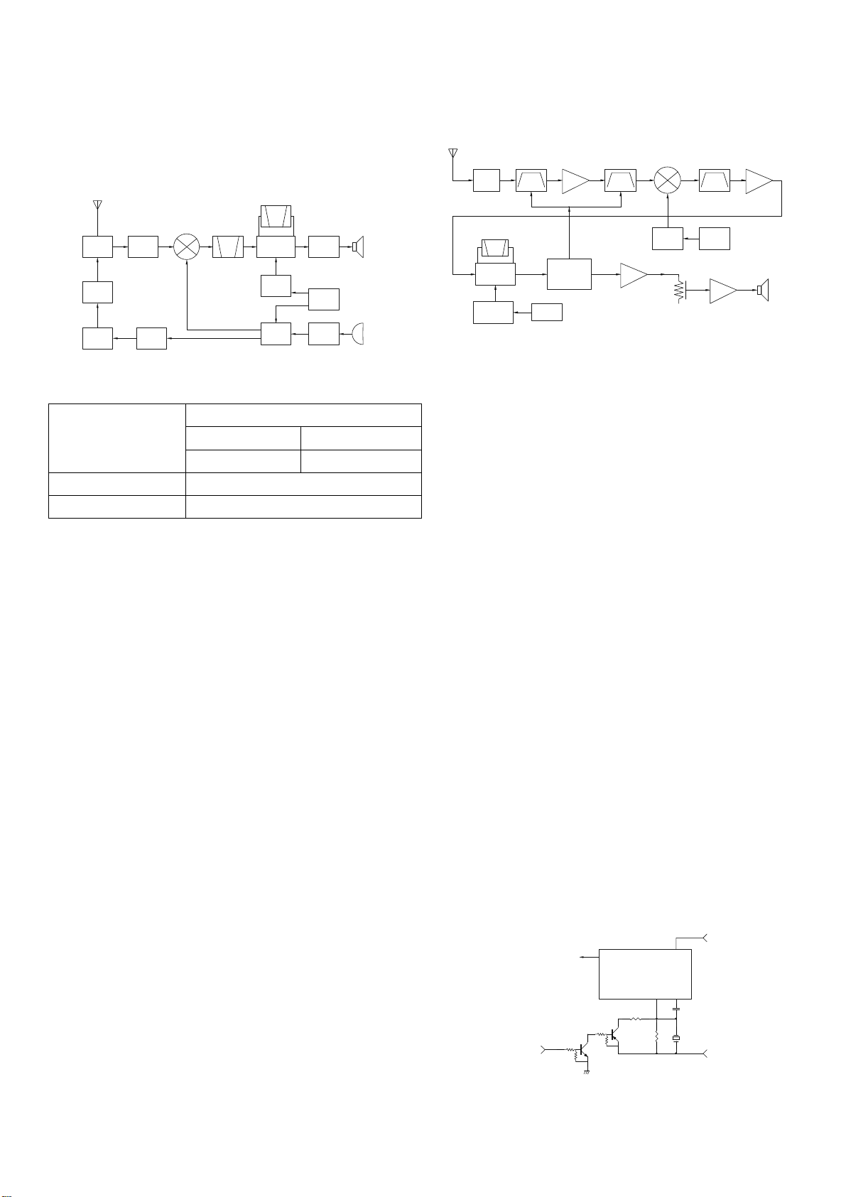
1. Frequency Configuration
The frequency configuration is shown in Figure 1 and
Table 1.
ANT
ANTSW
FINAL
RX/TX:66~88MHz
RF
AMP
MIX
MCF
38.850MHz
DRIVE
PRE
DRIVE
Fig. 1 Frequency configuration
Double super heterodyne
Reception method
1st IF Frequency 38.85MHz (Upper)
2nd IF Frequency 450kHz (Lower)
Transmission method VCO direct oscillation amplification
Modulation Variable reactance phase modulation
Table 1 Basic configuration
2. Receiver
2-1. Front-end RF Amplifier
The received signal from the antenna passes through a
low pass filter and then through a transmit/receive switching
circuit (antenna switch) and enters the band-pass filter
(L520, L521).
The signal passing through the band-pass filter (L520,
L521) is amplified by with an RF amplifier (Q506), passes
through a band-pass filter (L524, L522) and enters the first
mixer (Q507).
These band-pass filters are tuned to a desired frequency
by varicaps (D507, D508, D509, D510). A tuning voltage
corresponding to the desired signal is applied to each
varicap through the P76 terminal (pin 32) of the MPU (U201)
to tune to the receive frequency. (See Fig. 2)
2-2. First Mixer
The received signal passing through the band-pass filter
(L524, L522) is mixed with the first local signal generated by
the VCO by the first mixer (Q507) to produce a first IF signal
(38.85 MHz) (Upper heterodyne). The first IF signal passes
through a MCF (Monolithic crystal filter: XF3000 and
XF3001) to remove unwanted components.
The first IF signal passing through the MCF (XF3000 and
CF
450KHz
IFSYSTEM
MULTI PLY
PLL
VCO
38.40MHz
AMP
TCXO
AF
MIC
AMP
SP
19.200MHz
MIC
XF3001) is amplified by an IF amplifier (Q511) and the
resulting signal enters the FM IC (U503).
ANT
D501,D 502
D506
ANTSW
CF30 00
CF500
IF,MIX,DE T
U503
Q512
X2
MULTIPLY
2nd LocalOS C
BPF
X500
TCXO
RFAMP
Q506
VFO
Tunin gvoltage
U201
MPU
19.200M Hz
BPF
U204A
AFAMP
MIXER
Q507
VCO
XF3000 ,XF30 01
1st Local OSC
(PLL)
LV
MCF
PLL
AFPA AMP
U205
IFAMP
Q511
.
SP
Fig.2
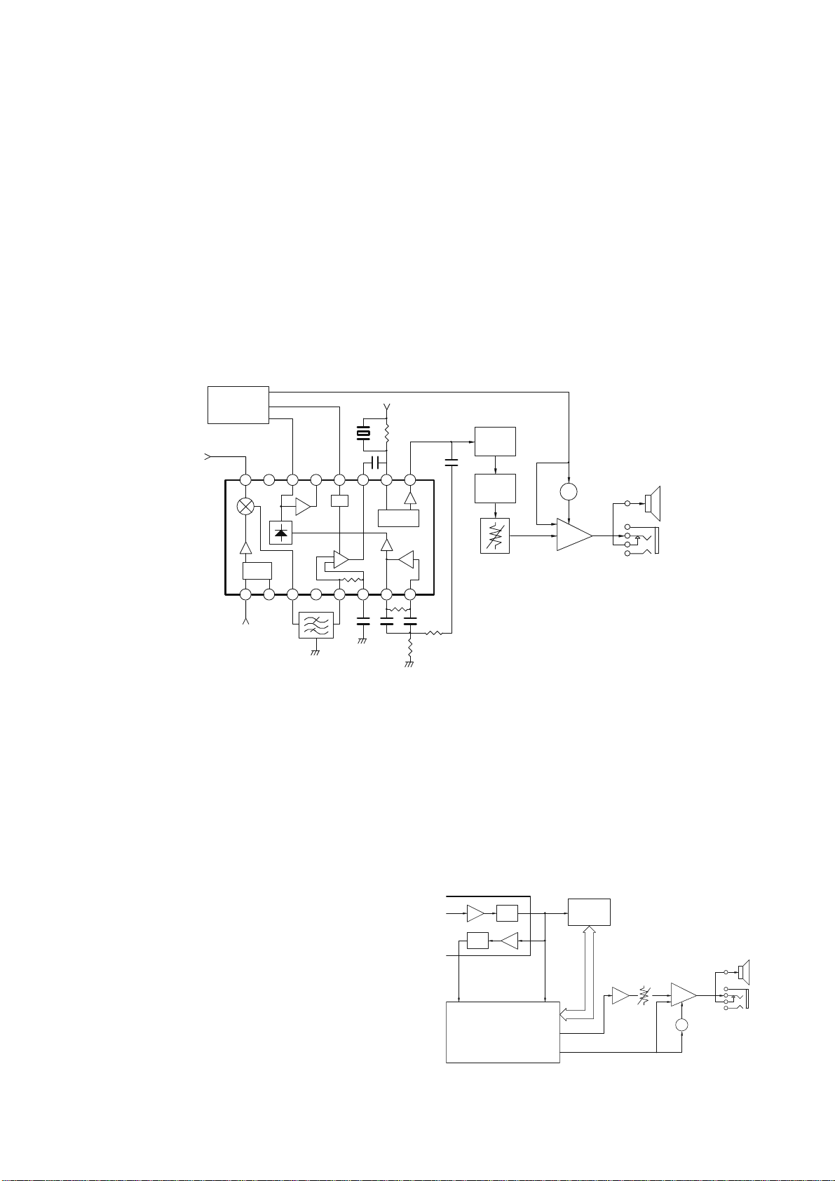
2-3. IF Amplifier Circuit
The first IF signal (38.85 MHz) amplified by the IF
amplifier (Q511) and the second IF signal (38.40 MHz)
generated by tripling the 19.200 MHz reference oscillator
frequency of the TCXO (X500) by Q512, are mixed in the
FM IC to produce a second IF signal (450 kHz) (Lower
heterodyne). The second IF signal passes through a
ceramic filter (CF3000) to remove unwanted components.
The second IF signal passing through the ceramic filter
(CF3000) passes through the IF amplifier in the FM IC
again and is detected to produced an audio signal. (See
Fig.2)
2-4. Wide/Narrow Switching Circuit
Narrow and Wide settings can be made for each channel
by switching the demodulation level. The WIDE (high level)
and NARROW (low level) data is output from U201, pin 11.
When a WIDE (high level) data is received, Q503 and
Q509 turn on.
When a NARROW (low level) data is received, Q503 and
Q509 turn off.
Q503 and Q509 turns on/off with the Wide/Narrow data and
the U503 detector output level is switched to maintain a
constant output level during wide or narrow signals. (See
Fig.3)
P63(U201)
H:Wide
L:Narrow
Q503
Q509
AFOUT
U503
FMSYSTEM
R509
R596
QUAD
Q511
IFOUT
C654
T3000
5R
Fig.3
1
Page 3
DV3066
1
7
CIRCUIT DESCRIPTION
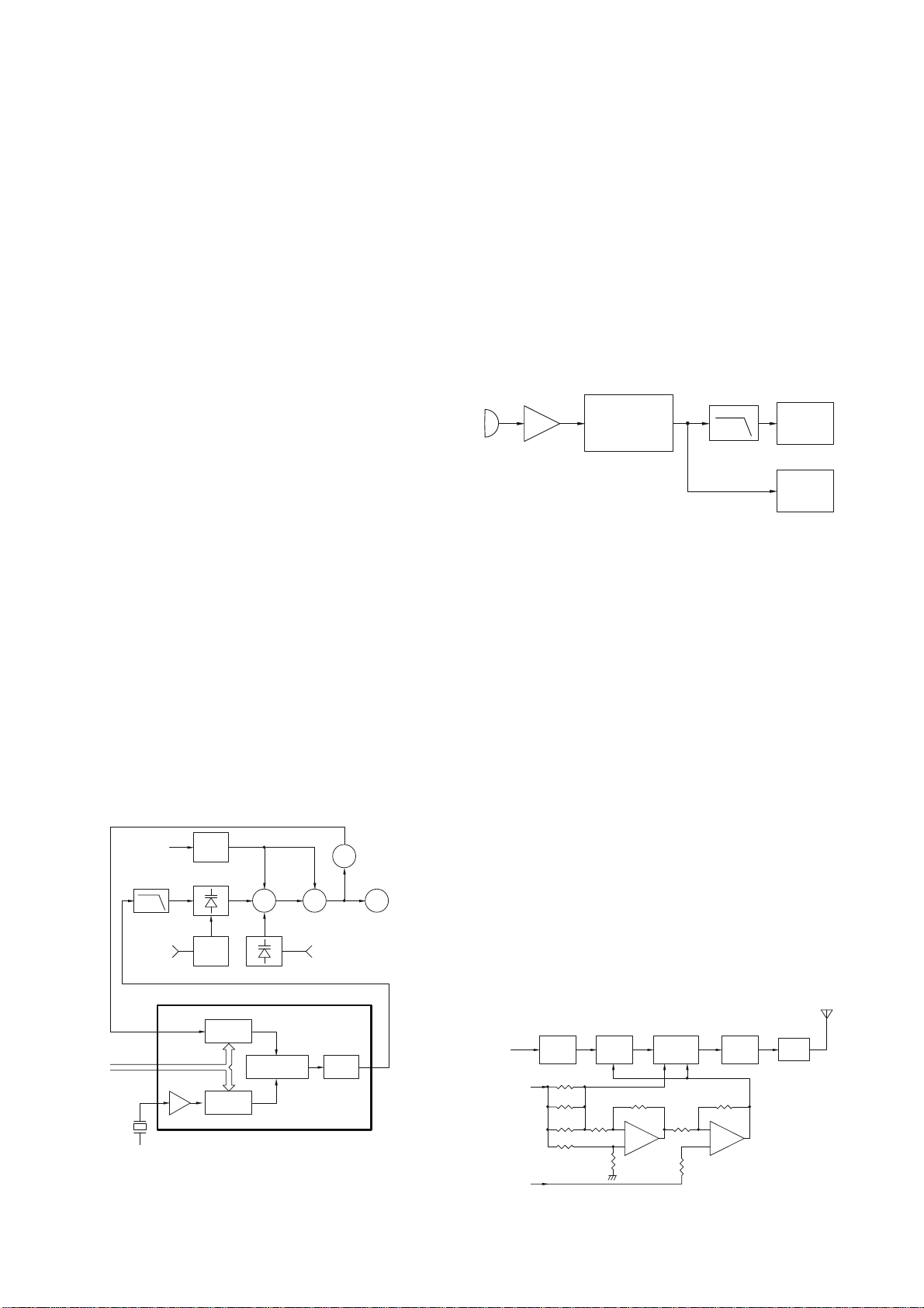
2-5. Squelch
A noise component is obtained by passing FM
detection output (FM IC pin 9) through an operational
amplifier in the FM IC and band-pass filter consisting of
R593, R594, R595, C580, C581. The noise component is
rectified in the FM IC to produce a DC voltage, which is
output from the N-REC terminal (pin 14) of the FM IC as
squelch voltage.
The squelch voltage enters the SQ terminal (pin 40) of
the MPU (U201) and is compared with the reference
voltage preset in the MPU to control audio signal
ON/OFF.
U201
MPU
1stIFinput
(38.85MHz)
U503
FMIC
2ndlocalOSC
(38.40MHz)
Fig.4
3. AF signal system
3-1. Audio amplifier circuit
The demodulated signal from U503 goes to Audio
processor through U201 (AF filtered, high-pass filtered,
de-emphasized , De-Scrambler, Expander, and Mux).
The signal then goes through an AF amplifier U204A
(1/2), an AF volume control, and is routed to an audio
power amplifier (U205), where it is amplified and output
to the internal speaker. (See Fig.5)
3-2. Receive Signalling
3-2-1 Low-speed data(CTCSS/DCS)
The output signal from FM IC (U503) enters the
microprocessor (U201). U201 determines whether the
CTCSS or DCS matches the preset value, and controls
the SP MUTE (PA1) and the speaker output sounds
according to the squelch results
SPMUTE
PA1
RSSI
P71
SQ
P70
MIX
Noise
comp
Rectifier
Buffer
Local
OSC
CF3000
450kHz
. (See Fig.5)
RSSI
T3000
IFAMP
111213141516
654321
5R
10
Quad ratu re
detector
Inve rter
AMP
R593
C581
R595
Nois e
AMP
AFOUT
9
87
To output sounds from the speaker, U201 sends a high
signal to the PA1 line and turns U205 on through Q201,
Q205, Q206 and Q207. (See Fig.4)
2-6. S Meter Circuit
The S meter voltage is output from the RSSI terminal
(pin 12) of the FM IC (U503) and input to the SM terminal
(pin 39) of the MPU. Then the voltage is converted from
analog to digital in the MPU to control the S meter display
on the LCD. (See Fig.4)
U201
AQUA
LPF
C580
R5594
U204A Q206,Q207
AMP
VOL
Q201,Q205,
U205
AFPA
SW
LS200
SP
J201
3-2-2 High-speed data (DTMF)
The DTMF input signal from the FM IC goes to pin 18
of U202. The signal is demodulated by DTMF
demodulator in U202. The demodulated data goes to the
MPU for processing. (See Fig.5)
AbandFMIFICU503
IF AMP
DET
SQL
40
P70
U201
MPU
LNOUT
AFsignal
98
PA1
DEMOD
U202
DTMFdecoder
P20,P21,P22,P23, P64,P65
27 Audio
92
SPMUTE
Fig.5
AFAMP
U204A(1/2)
VOL
U205
AFPA
Q201,Q205,Q206,Q20
SW
LS200
SP
J20
2
Page 4
DV3066
P
CIRCUIT DESCRIPTION
4. PLL frequency synthesizer
The PLL circuit generates the first local oscillator signal
for reception and the RF signal for transmission.
4-1.PLL circuit
A reference frequency of 5 kHz or 6.25 kHz is produced
by dividing the 19.20 MHz reference frequency of the
TCXO (X500) with PLL IC (U504). Comparison frequency
is produced by amplifying VCO output with an RF amplifier
(Q520) and dividing it with the PLL IC.
The PLL synthesizer with 5 kHz and 6.25 kHz step is
configured by comparing phases of the reference
frequency and comparison frequency.
The phase difference between reference frequency and
comparison frequency passes through a charge pump i n
the PLL IC, then ripples are removed with a loop filter with
low-range passing characteristics to produce VCO control
voltage (lock voltage). (See Fig. 6)
4-2.VCO circuit
The VCO produces a desired frequency directly with a
Colpits oscillation circuit containing an oscillation transistor
(Q518) used for both transmission and reception.
The VCO control voltage is applied to varicap (D516,
D517) to produce a desired frequency.
The PA0 terminal (pin 91) of the MPU (U201) goes "L"
during transmission, and the R/T control switch (Q519) is
turned OFF to change oscillation frequency. (See Fig. 6)
CHARGE
PUMP
Q520
RFAMP
Q516
RFAM
LPF
PA0
(U201 Pin91)
PLLDATA
19.200MHz
5C
D516, D517
REFOSC
Ripple
Fil te r
Q504
T/RSW
Q519
Q518
VCO
PLLICU504
I/N
I/M
Q517
BUFFAMP
MOD
5KHz/6.25KHz
PHASE
COMPARATOR
5KHz/6.25KHz
MOD
Fig.6
5. Transmission signal system
5-1.Microphone Amplifier Circuit
The audio signal from the microphone passes through a
microphone amplifier (U207) and enters Audio processor
(U201).U201 is composed of Compressor, high-pass
filtered, pre-emphasis, Mux, Scrambler, limiter, low-pass
filtered, and MOD circuit. The signal then passes through a
low-pass filter (splatter fiIter) Q208 and cuts 3kHz and
higher frequencies. The resulting signal goes to the VCO
through the VCO modulation terminal for direct FM
modulation. (See Fig. 7)
U207
MICAM P
C
MI
U201
MUP
Fig.7
5-2. Encode Signalling
CTCSS/DCS/DTMF
A necessary signal for CTCSS/DCS/DTMF encoding is
generated by U201 and FM-modulated to the PLL
reference signal. Since the reference OSC does not
modulate the loop characteristic frequency or higher,
modulation is performed at the VCO side by adjusting the
balance. (See Fig. 7)
5-3. Drive and Final Amplifier Circuit
The signal from the T/R switch (D503 is on) is amplified
by the pre-drive (Q515) and drive amplifier (Q513) to
50mW. The output of the drive amplifier is amplified by the
RF power amplifier (Q505) to 5W (1W when the power is
low).
The RF power amplifier consists of two MOS FET stages.
The output of the RF power amplifier is then passed
through the harmonic filter (LPF) and antenna switch
(D506) and applied to the antenna terminal.
(See Fig. 8)
Fro m
T/R SW
D503)(
Q515 Q513 Q505 D506
DRIVE
AMP
VDDVG VG
+BA TT
AMP
RF
R589
R590
R591
RF
FI NALAMP
APC
(U201)
U502A
(1/2 )
Fig.8
Q208
LPF
(SPLATTERFILTER)
ANTSW
U502B
(2/2 )
VCO
TCXO
ANT
LPF
3
Page 5
DV3066
5-4. APC Circuit
The APC circuit always monitors the current flowing
through the RF power amplifier (Q505) and keeps a
constant current. The voltage drop at R589, R590 and
R591 is caused by the current flowing through the RF
power amplifier and this voltage is applied to the differential
amplifier U502(1/2). U502 (2/2) compares the output
voltage of U502 (1/2) with the reference voltage from U201.
The output of U502 (2/2) controls the VG of the RF power
amplifier, Drive amplifier and Pre-Drive amplifier to make
both voltages the same.
The change of power high/low is carried out by the
change of the reference voltage. (See Fig. 8)
6 Control Circuit
The microprocessor (U201) operates at a clock of
32.768KHz.The control circuit consists of a microprocessor
(U201) and its peripheral circuits. It controls the TX-RX unit.
U201 mainly performs the following:
(1) Switching between transmission and reception by the
PTT signal input.
(2) Reading system, group, frequency, and program data
from the memory circuit.
(3) Sending frequency program data to the PLL.
(4) Controlling squelch on/off by the DC voltage from the
squelch circuit.
(5) Controlling the audio mute circuit by the decode data
input.
(6) Transmitting tone and encode data.
6-1.
Memory Circuit
Memory circuit consists of the MPU (U201 and an
EEPROM (U203). An EEPROM has a capacity of 64k bits
that contains the transceiver control program for the MPU
and data such as transceiver channels and operating
features. (See Fig. 9)
Fig.9
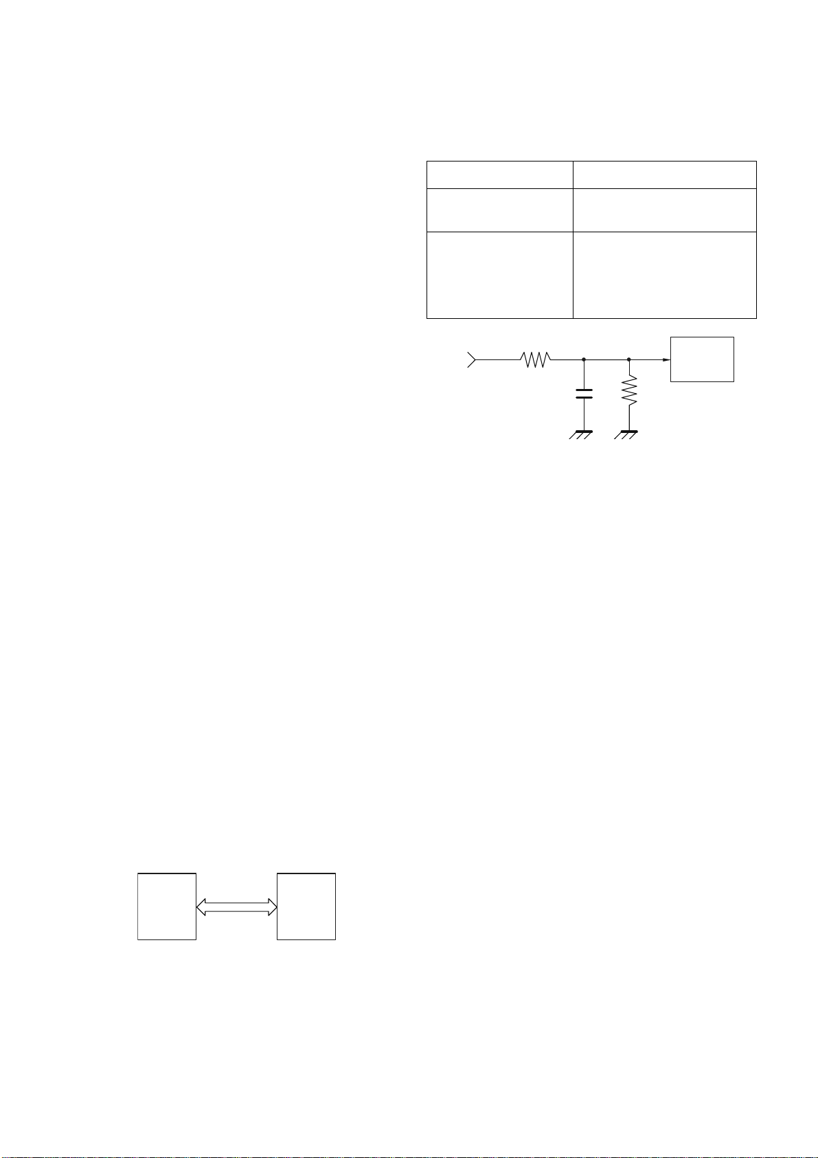
6-2. Low battery warning
The battery voltage is monitored by the microprocessor
(U201). When the battery voltage falls below the voltage
set by the Low Battery Warning adjustment, the red LED
U201
CPU
U203
EEP R OM
flashes to notify the operator that it is time to replace the
battery. If the battery voltage falls even more (approx.
6.0V), a beep sounds and transmission is stopped.
Low battery warning Battery condition
The red LED flashes
during transmission
The red LED flashes
and a continuous beep
sounds while PTT
pressed.
BATT1
R2 04
The battery voltage is low but
the transceiver is still usable.
The battery voltage is low and
the transceiver is not usable to
make calls.
U201
38
P72
C200
R2 03
MPU
Fig.10
7. Power Supply
There are four 5V power supplies for the microprocessor:
5M,5C,5R, and 5T. 5M for microprocessor is always output
while the power is on. 5M is always output, but turns off
when the power is turned off to prevent malfunction of the
microprocessor.
5C is a common 5V and is output when SAVE is not set to
OFF.
5R is 5V for reception and output during reception.
5T is 5V for transmission and output during transmission.
4
Page 6

SPARTS LIST
MAIN UNIT
Ref. No Parts No. Description of item Size (LxW)(mm) Qty Specification
C200 SMT CAPACITOR 0603 1 104±10% 50V
C201 SMT CAPACITOR 0603 1 102±10% 50V
C202 SMT CAPACITOR 0603 1 473±10% 50V
C203 SMT CAPACITOR 0603 1 102±10% 50V
C204 SMT CAPACITOR 0603 1 103±10% 50V
C205 SMT CAPACITOR 0603 1 104±10% 50V
C206-C212 SMT CAPACITOR 0603 7 103±10% 50V
C213 SMT CAPACITOR 0603 1 104±10% 50V
C214-C220 SMT CAPACITOR 0603 7 103±10% 50V
C221 SMT CAPACITOR 0603 1 183±10% 50V
C222 SMT CAPACITOR 0805 1 685±10% 50V
C223 SMT CAPACITOR 0603 1 224±10% 50V
C224 SMT CAPACITOR 0603 1 105±10% 50V
C225 SMT CAPACITOR 0603 1 NO USE
C226 SMT CAPACITOR 0805 1 105±10% 50V
C227 SMT CAPACITOR 0805 1 104±10% 50V
C228-C233 SMT CAPACITOR 0603 6 104±10% 50V
C234 SMT CAPACITOR 0603 1 224±10% 50V
C235-C237 SMT CAPACITOR 0603 3 104±10% 50V
C238 SMT CAPACITOR 0603 1 332±10% 50V
C239 SMT CAPACITOR 0603 1 223±10% 50V
C240 SMT CAPACITOR 0603 1 104±10% 50V
C241 SMT CAPACITOR 0603 1 224±10% 50V
C242 SMT CAPACITOR 0603 1 104±10% 50V
C243 SMT CAPACITOR 0603 1 224±10% 50V
C244-C245 SMT CAPACITOR 0603 2 104±10% 50V
C246 SMT CAPACITOR 0603 1 273±10% 50V
DV3066
5
Page 7

DV3066
PARTS LIST
Ref. No Parts No. Description of item Size (LxW)(mm) Qty Specification
C247-C248 SMT CAPACITOR 0603 2 20P±5% 50V
C249 SMT RESISTOR 0603 1 0R
C250 SMT CAPACITOR 0603 1 47P±5% 50V
C251 SMT CAPACITOR 0603 1 105±10% 50V
C252 SMT CAPACITOR 0603 1 100P±5% 50V
C253 SMT CAPACITOR 0603 1 56P±5% 50V
C254 SMT CAPACITOR 0603 1 220P±5% 50V
C255-C258 SMT CAPACITOR 0805 1 225±10% 50V
C259-C260 SMT CAPACITOR 0603 2 100P±5% 50V
C261 SMT RESISTOR 0603 1 100R±5%
C262 SMT CAPACITOR 0603 1 103±10% 50V
C263 SMT CAPACITOR 0603 1 104±10% 50V
C264 SMT CAPACITOR 0603 1 30P±5% 50V
C265 SMT CAPACITOR 0603 1 103±5% 50V
C267 SMT CAPACITOR 0603 1 15P±5% 50V
C268 SMT CAPACITOR 0603 1 470P±5% 50V
C269 SMT CAPACITOR 0603 1 272±5% 50V
C270 SMT CAPACITOR 0603 1 473±5% 50V
C271 SMT CAPACITOR 0603 1 332±5% 50V
C272 SMT CAPACITOR 0603 1 224±10% 50V
C273 SMT CAPACITOR 0603 1 472±10% 50V
C274 SMT CAPACITOR 0603 1 332±5% 50V
C275 SMT CAPACITOR 0603 1 105±10% 50V
C276 SMT CAPACITOR 0603 1 680P±5% 50V
C277 SMT CAPACITOR 0603 1 332±10% 50V
C278 SMT CAPACITOR 0805 1 475±10% 50V
C279 SMT CAPACITOR 0805 1 225±10% 50V
C280 SMT CAPACITOR 0603 1 103±10% 50V
6
Page 8

DV3066
PARTS LIST
Ref. No Parts No. Description of item Size (LxW)(mm) Qty Specification
C281 SMT CAPACITOR 0603 1 102±10% 50V
C282 SMT CAPACITOR 0603 1 104±10% 50V
C283 SMT CAPACITOR 0603 1 122±10% 50V
C284-C286 SMT CAPACITOR 0603 3 103±10% 50V
C287 SMT CAPACITOR 0603 1 470P±5% 50V
C288 SMT CAPACITOR 0603 1 104±10% 50V
C500 SMT CAPACITOR 0603 1 103±10% 50V
C501 SMT CAPACITOR 0603 1 102±10% 50V
C502 SMT CAPACITOR 0603 1 103±10% 50V
C503-C508 SMT CAPACITOR 0603 6 102±10% 50V
C509 SMT CAPACITOR 0603 1 103±10% 50V
C510 SMT CAPACITOR 0603 1 104±10% 50V
C511 SMT CAPACITOR 0603 1 102±10% 50V
C512-C525 SMT CAPACITOR 0603 14 102±10% 50V
C526-C536 SMT CAPACITOR 0603 11 103±10% 50V
C537-C551 SMT CAPACITOR 0603 15 103±10% 50V
C552 SMT CAPACITOR 0603 1 103±10% 50V
C553 SMT CAPACITOR 0603 1 103±10% 50V
C554 SMT CAPACITOR 0805 1 105±10% 50V
C555-C556 SMT CAPACITOR 0603 2 105±10% 50V
C557 SMT CAPACITOR 0603 1 104±10% 50V
C558-C560 SMT CAPACITOR 0603 3 104±10% 50V
C561 SMT CAPACITOR 0603 1 102±10% 50V
C562-C565 SMT CAPACITOR 0603 4 104±10% 50V
C566 SMT CAPACITOR 0603 1 224±10% 50V
C567 SMT CAPACITOR 0805 1 470P±10% 50V
C568 SMT CAPACITOR 0603 1 15P±5% 50V
C569 SMT CAPACITOR 0603 1 9P±0.1P 50V
C570 SMT CAPACITOR 0603 1 120±5% 50V
7
Page 9

DV3066
PARTS LIST
Ref. No Parts No. Description of item Size (LxW)(mm) Qty Specification
C571 SMT CAPACITOR 0603 1 12P±5% 50V
C572 SMT CAPACITOR 0603 1 10P±0.25P 50V
C573 SMT CAPACITOR 0603 1 NO USE
C574 SMT CAPACITOR 0603 1 6P±0.1P 50V
C575-C577 SMT CAPACITOR 0603 3 NO USE
C578 SMT CAPACITOR 0603 1 33P±5% 50V
C579 SMT RESISTOR 0603 1 2.2K±5%
C580-C581 SMT CAPACITOR 0603 2 220P±5% 50V
C582-C583 SMT CAPACITOR 0804 2 225±10% 50V
C584 SMT CAPACITOR 0603 1 102±10% 50V
C585 SMT CAPACITOR 0603 1 100P±5% 50V
C586 SMT CAPACITOR 0603 1 33P±5% 50V
C587 SMT CAPACITOR 0603 1 100P±5% 50V
C588 SMT CAPACITOR 0603 1 102±10% 50V
C589-C591 SMT CAPACITOR 0603 3 100P±5% 50V
C592 SMT CAPACITOR 0603 1 27P±5% 50V
C593 SMT CAPACITOR 0603 1 102±10% 50V
C594-C596 SMT CAPACITOR 0603 3 470P±10% 50V
C597 SMT CAPACITOR 0603 1 102±10% 50V
C598 SMT CAPACITOR 0603 1 103±10% 50V
C599 SMT CAPACITOR 0603 1 6P±0.1P 50V
C600 SMT CAPACITOR 0603 1 102±10% 50V
C601-C607 SMT CAPACITOR 0603 7 470P±10% 50V
C608 SMT CAPACITOR 0603 1 56P±5% 50V
C609 SMT CAPACITOR 0603 1 102±10% 50V
C610-C612 SMT CAPACITOR 0603 3 470P±10% 50V
C613 SMT CAPACITOR 0603 1 NO USE
C614 SMT CAPACITOR 0603 1 27P±5% 50V
8
Page 10

DV3066
PARTS LIST
Ref. No Parts No. Description of item Size (LxW)(mm) Qty Specification
C615 SMT CAPACITOR 0603 1 15P±5% 50V
C616 SMT CAPACITOR 0603 1 18P±5% 50V
C617 SMT CAPACITOR 0603 1 2P±0.1P 50V
C618 SMT CAPACITOR 0603 1 24P±5% 50V
C619 SMT CAPACITOR 0603 1 5P±0.1P 50V
C620 SMT CAPACITOR 0603 1 2P±0.1P 50V
C621 SMT CAPACITOR 0603 1 5P±0.1P 50V
C622 SMT CAPACITOR 0603 1 0.5P±0.1P 50V
C623 SMT CAPACITOR 0603 1 33P±5% 50V
C624 SMT CAPACITOR 0603 1 39P±5% 50V
C625 SMT CAPACITOR 0603 1 10P±5% 50V
C626 SMT CAPACITOR 0603 1 5P±0.1P 50V
C627 SMT CAPACITOR 0603 1 10P±0.25P 50V
C628 SMT CAPACITOR 0603 1 NO USE
C629 SMT CAPACITOR 0603 1 39P±5% 50V
C630 SMT CAPACITOR 0603 1 47P±5% 50V
C631 SMT CAPACITOR 0603 1 39P±5% 50V
C632 SMT CAPACITOR 0603 1 12P±5% 50V
C633 SMT CAPACITOR 0603 1 24P±5% 50V
C634 SMT CAPACITOR 0603 1 5P±0.1P 50V
C635 SMT CAPACITOR 0603 1 27P±5% 50V
C636 SMT CAPACITOR 0603 1 3P±0.1P 50V
C637 SMT CAPACITOR 0603 1 30P±5% 50V
C638 SMT CAPACITOR 0603 1 150P±5% 50V
C639 SMT CAPACITOR 0603 1 68P±5% 50V
C640 SMT CAPACITOR 0603 1 27P±5% 50V
C641 SMT CAPACITOR 0603 1 56P±5% 50V
C642-C645 SMT CAPACITOR 0603 4 27P±5% 50V
9
Page 11

DV3066
PARTS LIST
Ref. No Parts No. Description of item Size (LxW)(mm) Qty Specification
C646 SMT CAPACITOR 0603 1 18P±5% 50V
C647 SMT CAPACITOR 0603 1 10P±0.25P 50V
C648 SMT CAPACITOR 0603 1 NO USE
C649 SMT CAPACITOR 0603 1 2P±0.1P 50V
C650-C651 SMT CAPACITOR 0603 2 15P±5% 50V
C652 SMT SMALL FIXED INDUCTOR 0603 1 27nH
C653 SMT CAPACITOR 0603 1 47P±5% 50V
C654 SMT CAPACITOR 0603 1 82P±5% 50V
C655 SMT CAPACITOR 0603 1 27P±5% 50V
C656 SMT CAPACITOR 0603 1 2P±0.1P 50V
C657 SMT CAPACITOR 0603 1 1.5 P±0.1P 50V
C658 SMT CAPACITOR 0603 1 82P±5% 50V
C659 SMT CAPACITOR 0603 1 24P±5% 50V
C660 SMT CAPACITOR 0603 1 47P±5% 50V
C661 SMT CAPACITOR 0603 1 27P±5% 50V
C662 SMT CAPACITOR 0603 1 22P±5% 50V
C663 SMT CAPACITOR 0603 1 30P±5% 50V
C664 SMT CAPACITOR 0603 1 27P±5% 50V
C665 SMT CAPACITOR 0603 1 102±10% 50V
C666-C667 SMT CAPACITOR 0603 2 NO USE
C900 SMT CAPACITOR 0603 1 NO USE
C901 SMT CAPACITOR 0603 1 NO USE
C902 SMT CAPACITOR 0603 1 NO USE
C903 SMT CAPACITOR 0603 1 NO USE
C904 SMT CAPACITOR 0603 1 NO USE
C907 SMT CAPACITOR 0603 1 NO USE
E200 SMT TANT ALUM CAPACITOR A type 1 10uF±20% 10V
E205 SMT TANT ALUM CAPACITOR A type 1 22uF±20% 6.3V
10
Page 12

DV3066
PARTS LIST
Ref. No Parts No. Description of item Size (LxW)(mm) Qty Specification
E500-E503 SMT TANTALUM CAPACITOR A type 4 10uF±20% 10V
E504 SMT TANT ALUM CAPACITOR A type
E505 SMT TANT ALUM CAPACITOR A type 1 0.47uF±20% 35V
E506 SMT TANT ALUM CAPACITOR A type 1 0.22uF±20% 35V
E507 SMT TANT ALUM CAPACITOR A type
R200 SMT RESISTOR 0603 1 5.1K±5%
R201 SMT RESISTOR 0603 1 47K±5%
R202 SMT RESISTOR 0603 1 100K±5%
R203 SMT RESISTOR 0603 1 51K±1%
R204 SMT RESISTOR 0603 1 150K±1%
R205 SMT RESISTOR 0603 1 560R±5%
R206 SMT RESISTOR 0603 1 1.8K±5%
R207 SMT RESISTOR 0603 1 100R±5%
R208 SMT RESISTOR 0603 1 10K±5%
R209 SMT CAPACITOR 0603 1 564±10% 50V
R210 SMT RESISTOR 0603 1 1K±5%
R211 SMT RESISTOR 0603 1 100K±5%
R212 SMT RESISTOR 0603 1 NO USE
R213 SMT RESISTOR 0603 1 560K±5%
R214 SMT RESISTOR 0603 1 NO USE
R215-R216 SMT RESISTOR 0603 2 470K±5%
R217-R218 SMT RESISTOR 0603 2 220R±5%
R219 SMT RESISTOR 0603 1 10R±5%
R220 SMT RESISTOR 0603 1 100K±5%
R221-R222 SMT RESISTOR 0603 2 10K±5%
R223 SMT RESISTOR 0603 1 10R±5%
R224 SMT RESISTOR 0603 1 10K±5%
R225 SMT RESISTOR 0603 1 1K±5%
R226-R227 SMT RESISTOR 0603 2 10K±5%
1
4.7uF±20% 10V
1
22uF±20% 16V
11
Page 13

DV3066
PARTS LIST
Ref. No Parts No. Description of item Size (LxW)(mm) Qty Specification
R228 SMT RESISTOR 0603 1 10K±5%
R229-R233 SMT RESISTOR 0603 5 10K±5%
R234 SMT RESISTOR 0603 1 100R±5%
R235 SMT RESISTOR 0603 1 1K±5%
R236 SMT RESISTOR 0603 1 100K±5%
R237 SMT RESISTOR 0603 1 10K±5%
R238 SMT RESISTOR 0603 1 2.2K±5%
R239 SMT RESISTOR 0603 1 1K±5%
R240 SMT RESISTOR 0603 1 33K±5%
R241 SMT RESISTOR 0603 1 NO USE
R242 SMT RESISTOR 0603 1 22K±5%
R243 SMT RESISTOR 0805 1 NO USE
R244-R245 SMT RESISTOR 0603 2 33K±5%
R246 SMT RESISTOR 0603 1 220K±5%
R247 SMT RESISTOR 0603 1 100K±5%
R248-R249 SMT RESISTOR 0603 2 1K±5%
R250-R253 SMT RESISTOR 0603 4 4.7K±5%
R254 SMT RESISTOR 0603 1 2.2K±5%
R255 SMT RESISTOR 0603 1 0R
R256 SMT RESISTOR 0603 1 120K±5%
R257 SMT RESISTOR 0603 1 47K±5%
R258 SMT RESISTOR 0603 1 33K±5%
R259 SMT RESISTOR 0603 1 22R±5%
R260 SMT RESISTOR 0603 1 120K±5%
R261 SMT RESISTOR 0603 1 330K±5%
R262 SMT RESISTOR 0603 1 330K±5%
R263 SMT RESISTOR 0603 1 51K±5%
R264 SMT RESISTOR 0603 1 100K±5%
R265 SMT RESISTOR 0603 1 27K±5%
12
Page 14

DV3066
PARTS LIST
Ref. No Parts No. Description of item Size (LxW)(mm) Qty Specification
R266 SMT RESISTOR 0603 1 NO USE
R267 SMT RESISTOR 0603 1 1.8M±5%
R268 SMT RESISTOR 0603 1 6.8K±5%
R269 SMT RESISTOR 0603 1 3.3K±5%
R270 SMT RESISTOR 0603 1 300K±5%
R271 SMT RESISTOR 0603 1 10K±5%
R272 SMT RESISTOR 0603 1 1K±5%
R273 SMT RESISTOR 0603 1 100K±5%
R274 SMT RESISTOR 0603 1 470R±5%
R275 SMT RESISTOR 0603 1 1K±5%
R276 SMT RESISTOR 0603 1 4.7K±5%
R277 SMT RESISTOR 0603 1 10K±5%
R278 SMT RESISTOR 0603 1 NO USE
R500 SMT RESISTOR 0603 1 51K±5%
R501 SMT RESISTOR 0603 1 120K±5%
R502-R507 SMT RESISTOR 0603 6 150K±1%
R508 SMT RESISTOR 0603 1 560R±5%
R509-R510 SMT RESISTOR 0603 2 1.8K±5%
R511 SMT RESISTOR 0603 1 56 K±5%
R512-R513 SMT RESISTOR 0603 2 NO USE
R514 SMT RESISTOR 0603 1 100R±5%
R515 SMT RESISTOR 0603 1 330R±5%
R516 SMT RESISTOR 0603 1 3.3K±5%
R517 SMT RESISTOR 0603 1 2.2K±5%
R518 SMT RESISTOR 0603 1 220R±5%
R519-R523 SMT RESISTOR 0603 5 10K±5%
R524-R527 SMT RESISTOR 0603 4 100R±5%
R528 SMT RESISTOR 0603 1 22R±5%
R529 SMT RESISTOR 0603 1 100R±5%
13
Page 15

DV3066
PARTS LIST
Ref. No Parts No. Description of item Size (LxW)(mm) Qty Specification
R530 SMT RESISTOR 0603 1 330R±5%
R531 SMT RESISTOR 0603 1 100R±5%
R532 SMT RESISTOR 0603 1 33R±5%
R533 SMT RESISTOR 0603 1 56K±5%
R534 SMT RESISTOR 0603 1 47K±5%
R535 SMT RESISTOR 0603 1 56K±5%
R536-R537 SMT RESISTOR 0603 2 150K±5%
R538 SMT RESISTOR 0603 1 100K±5%
R539 SMT RESISTOR 0603 1 22K±5%
R540-R543 SMT RESISTOR 0603 4 100K±5%
R544 SMT RESISTOR 0603 1 4.7K±5%
R545 SMT RESISTOR 0603 1 0R
R547 SMT RESISTOR 0603 1 680R±5%
R548 SMT RESISTOR 0603 1 47K±5%
R549 SMT RESISTOR 0603 1 4.7K±5%
R550-R551 SMT RESISTOR 0603 2 2.2K±5%
R552 SMT RESISTOR 0603 1 22R±5%
R553 SMT RESISTOR 0603 1 0R
R554 SMT RESISTOR 0603 1 12K±5%
R555 SMT RESISTOR 0603 1 82K±5%
R556 SMT RESISTOR 0603 1 33K±5%
R557 SMT RESISTOR 0603 1 15K±5%
R558 SMT RESISTOR 0603 1 82K±5%
R559 SMT RESISTOR 0603 1 100K±5%
R560 SMT RESISTOR 0603 1 120K±5%
R561-R562 SMT RESISTOR 0603 2 68K±5%
R563 SMT RESISTOR 0603 1 47K±5%
R564 SMT RESISTOR 0603 1 100K±5%
R565 SMT RESISTOR 0603 1 330K±5%
14
Page 16

DV3066
PARTS LIST
Ref. No Parts No. Description of item Size (LxW)(mm) Qty Specification
R566-R567 SMT RESISTOR 0603 2 1.2K±5%
R568 SMT RESISTOR 0603 1 6.8K±5%
R569-R571 SMT RESISTOR 0603 3 3.3K±5%
R572 SMT RESISTOR 0603 1 47R±5%
R573 SMT RESISTOR 0603 1 47R±5%
R574 SMT RESISTOR 0805 1 120R±5%
R575-R579 SMT RESISTOR 0603 5 1M±5%
R580-R581 SMT RESISTOR 0805 2 10R±5%
R582 SMT RESISTOR 0603 1 56R±5%
R583 SMT RESISTOR 0603 1 27K±5%
R584 SMT RESISTOR 0603 1 82K±5%
R585 SMT RESISTOR 0603 1 10R±5%
R586 SMT RESISTOR 0603 1 820R±5%
R587 SMT RESISTOR 0603 1 560R±5%
R588 SMT RESISTOR 0603 1 390R±5%
R589-R591 SMT RESISTOR 1206 3 0.36R±5%
R592 SMT RESISTOR 0603 1 220K±5%
R593 SMT RESISTOR 0603 1 270K±5%
R594 SMT RESISTOR 0603 1 180K±5%
R595 SMT RESISTOR 0603 1 3.9K±5%
R596 SMT RESISTOR 0603 1 1.5K±5%
R597 SMT RESISTOR 0603 1 180R±5%
R598 SMT RESISTOR 0603 1 330R±5%
R599 SMT RESISTOR 0603 1 680R±5%
R600 SMT RESISTOR 0603 1 0R
R601 SMT RESISTOR 0603 1 100R±5%
R602-R603 SMT RESISTOR 0603 2 2.7K±5%
R604 SMT RESISTOR 0603 1 4.7K±5%
R605 SMT RESISTOR 0603 1 6.8K±5%
15
Page 17

DV3066
PARTS LIST
Ref. No Parts No. Description of item Size (LxW)(mm) Qty Specification
R606 SMT RESISTOR 0603 1 8.2K±5%
R607-R610 SMT RESISTOR 0603 7 NO USE
R900 SMT RESISTOR 0603 1 NO USE
R903 SMT RESISTOR 0603 1 NO USE
RP200-RP201
RP202-RP203 SMT RESISTOR ARRAY 4D03 2 5.1K×4
RP204 SMT RESISTOR ARRAY 4D03 1 1K×4
RP205 SMT RESISTOR ARRAY 4D03 1 47K×4
RP500 SMT RESISTOR ARRAY 4D03 1 1K×4
VR500 SMT RESISTOR 0805 1 2.2K±5%
D2002 SMT LIGHTED DIODE 0603 1 GREEN
D2003 SMT LIGHTED DIODE 0603 1 RED
D202 SMT DIODE SC-70 1 1SS372
D204 SMT DIODE SC-79 1 BA892
D500-D501 SMT DIODE 0603 2 BA892
D502-D503 SMT DIODE 0603 2 BA892
D504-D505 SMT DIODE 0603 2 BA892
D506 SMT DIODE 1206 1 BA592
D507-D510 SMT VARIABLE CAPACITANCE DIODE SC-79 4 HVC376
D511 SMT VARIABLE CAPACITANCE DIODE 0603 1 BA592
D512 SMT NTC RESISTOR 0603 1 47K
D513 SMT ZENER DIODE 0805 1 NO USE
D514 SMT DIODE 0603 1 1SS400
D515 SMT VARIABLE CAPACITANCE DIODE SC-79 1 MA2S360
D516-D517 SMT VARIABLE CAPACITANCE DIODE 0603 2 JDV2S14E(FH)
D518 SMT DIODE 0603 1 NO USE
D519 SMT DIODE SC-79 1 BA892
Q200 SMT DIGITAL TRANSISTOR EMT3 1 DTC144TE
SMT RESISTOR ARRAY 4D03
2 10K×4
16
Page 18

DV3066
PARTS LIST
Ref. No Parts No. Description of item Size (LxW)(mm) Qty Specification
Q200 SMT DIGITAL TRANSISTOR SOT-523 1 DTC144TE
Q201 SMT TRANSISTOR SC-89 1 2SB1132
Q202 SMT DIGITAL TRANSI STOR EMT3 1 DTC144EE
Q205-Q206 SMT DIGITAL TRANSISTOR EMT3 2 2SC5383
Q207 SMT DIGITAL TRANSI STOR EMT3 1 RT1N141U
Q208 SMT DIGITAL TRANSI STOR EMT3 1 2SC5383
Q209 SMT DIGITAL TRANSI STOR EMT3 1 DTA123JE
Q210 SMT DIGITAL TRANSI STOR EMT3 1 RT1N141U
Q211 SMT DIGITAL TRANSI STOR EMT3 1 DTC144TE
Q212 SMT DIGITAL TRANSI STOR EMT3 1 RTIN141U
Q213 SMT FET SC-70 1 2SD2351
Q500 SMT DIGITAL TRANSI STOR EMT3 1 DTA144EE
Q501-Q503 SMT DIGITAL TRANSISTOR EMT3 3 RT1N141U
Q504 SMT DIGITAL TRANSISTOR EMT3 1 2SC4617
Q505 SMT FET PLD 1 2SK3476
Q506-Q507 SMT FET SOT-143 2 3SK318
Q508 SMT DIGITAL TRANSISTOR EMT3 1 DTA143ZE
Q509-Q510 SMT DIGITAL TRANSISTOR EMT3 2 RT1P141U
Q511-Q512 SMT TRANSISTOR SC-70 2 2SC4082
Q513
Q514 SMT DIGITAL TRANSI STOR EMT3 1 DTC144EE
Q515 SMT TRANSISTOR SOT-23 1 2SC3356
Q516-Q518 SMT TRANSISTOR SC-70 3 2SC4226
Q519 SMT FET EMT3 1 2SK1824
Q520 SMT TRANSISTOR SC-70 1 2SC4226
Q521 SMT FET EMT3 1 NO USE
U200 SMT IC SOT-23 1 SJ73L27S
SMT FET SOT-89 1 2SK3078A
17
Page 19

DV3066
PARTS LIST
Ref. No Parts No. Description of item Size (LxW)(mm) Qty Specification
U201 SMT IC LQFP-100 1 SRT3210
U202 SMT IC SSOP-20 1 SX9170
U203 SMT IC SOP8 1 AT24C64RM
U204 SMT IC SSOP8 1 NLM2904V
U205
U206 SMT IC SOT-25-5 1 TJ5205SF-33
U207 SMT IC SOT-25-5 1 TA75S01F
U208 SMT IC SOP-8 1 LY58-ML
U500-U501 SMT IC SOT-25-5 2 TJ5205SF-50
U502 SMT IC SSOP14 1 LM2904V
U503 SMT IC SSOP16 1 AA32416
U504 SMT IC SSOP20 1 LMX2336LTM
U900 SMT IC QFN24-4*4 1 NO USE
L200 SMT FERRITE BEAD (BLACK) 0603 1 271T
L202 SMT FERRITE BEAD (BLACK) 0603 1 271T
L204-L205 SMT FERRITE BEAD (BLACK) 0603 2 271T
L500-L503 SMT FERRITE BEAD (BLACK) 0603 4 271T
L504 SMT AIR-CORE COIL 1 5T
L505 SMT FERRITE BEAD (BLACK) 0603 1 271T
L506 SMT SMALL FIXED INDUCTOR (BLOVE) 2520 1 1uH
L507 SMT CAPACITOR 0603 1 220P±5% 50V
L508-L509 SMT WIRE WOUND INDUCTOR 0805 2 82nH
L510 SMT AIR-CORE COIL 1 8T
L511 SMT WIRE WOUND INDUCTOR 1206 1 82nH
L512 SMT WIRE WOUND INDUCTOR 0805 1 100nH
L513-L514 SMT FERRITE BEAD (BLACK) 0805 2 30T
L515 SMT WIRE WOUND INDUCTOR 1206 1 100nH
L516 SMT WIRE WOUND INDUCTOR 2520 1 2.2uH
L517 SMT WIRE WOUND INDUCTOR 0805 1 270nH
SMT IC MSOP-8
1 M4890
18
Page 20

DV3066
PARTS LIST
Ref. No Parts No. Description of item Size (LxW)(mm) Qty Specification
L518 SMT SMALL FIXED INDUCTOR 0603 1 56nH
L519 SMT RESISTOR 0603 1 0R
L520 SMT WIRE WOUND INDUCTOR 0805 1 150nH
L521-L522 SMT WIRE WOUND INDUCTOR 0805 2 220nH
L523 SMT AIR-CORE COIL 1 5T
L524-L525 SMT WIRE WOUND INDUCTOR 0805 2 220nH
L526 SMT WIRE WOUND INDUCTOR 0805 1 150nH
L527 SMT SMALL FIXED INDUCTOR 0603 1 NO USE
L528 SMT SMALL FIXED INDUCTOR 0603 1 82nH
L529 SMT SMALL FIXED INDUCTOR 0603 1 270nH
L530 SMT SMALL FIXED INDUCTOR 0603 1 470nH
L531 SMT SMALL FIXED INDUCTOR (BLOVE) 2520 1 560nH
L532 SMT SMALL FIXED INDUCTOR 0603 1 220nH
L533 SMT SMALL FIXED INDUCTOR 0603 1 150nH
L534 SMT SMALL FIXED INDUCTOR 0603 1 10uH
L536 SMT WIRE WOUND INDUCTOR 0805 1 68nH
L538 SMT WIRE WOUND INDUCTOR 0805 1 68NH
L539 SMT SMALL FIXED INDUCTOR 0603 1 10uH
L540-L541 SMT SMALL FIXED INDUCTOR 0603 2 560nH
L542 SMT SMALL FIXED INDUCTOR 0603 1 2.2uH
L543 SMT SMALL FIXED INDUCTOR 0603 1 150nH
L901 SMT SMALL FIXED INDUCTOR 0603 1 NO USE
CF3000 CERAMIC FILTER 1 CFW450F
T3000 CERAMIC FILTER 1 450K(C24)
J200 FLAT CABLE CONNECTOR SSOI20F 1 0.5S-1X-20PWB
J2000 MIC SOCKET 3.5mm 1 SK-3.5STEREO
J2001 SPEAKER SOCKET 2.5mm 1 SK-2.5STEREO
J2002 SWITCH PIN 1 CON9_1.27
19
Page 21

DV3066
PARTS LIST
Ref. No Parts No. Description of item Size (LxW)(mm) Qty Specification
LS200 SPEAKER 1 16R/1W
MK2000 MICROPHONE 1 MIC-9.7
W1 VOLUME SWITCH 1 08110SNAXV020016-B103
S2 CHANNEL SWITCH 1 RE08120HX-V02-0607A
S2000 FP1 BUTTON 1 FP1
S2001 FP2 BUTTON
S2002 TRANSMITTING BUTTON 1 PTT
X500 SMT TCXO 1 19.200MHz
XF3000-X3001 SMT CRYSTAL FILTER 2 38.850MHz
Y201 SMT CRYSTAL 1 32.768KHz
Y202 CERAMIC FILTER 1 3.58MHz
20
1
FP2
Page 22

DV3066
ADJUSTMENT
Common Section
Item Condition
1. Setting
2. VCO lock
voltage
RX
3. VCO lock
voltage
TX
1) BATT terminal voltage: 7.4V
2) SSG standard modulation
[Wide] MOD:1kHz,DEV:3kHz
[Narrow] MOD:1kHz,DEV:1.5kHz
1) CH: high
2) CH: Low
3) CH: high
PTT:ON
4) CH: Low
PTT:ON
Transmitter section
Item Condition
1. Transmit
frequency
2. High
power
Adjust
3. Min power
Adjust
4. Low power
Adjust
5. MAX DEV
Adjust
[Wide]
[Narrow]
6. MIC
Sensitivity
[Wide]
[Narrow]
TEST CH: center
PTT: ON
TEST CH: low, center, high
Battery terminal: 7.4V
PTT: ON
CH: low, center, high
Battery terminal: 7.4V
PTT: ON
CH: low, center, high
Battery terminal: 7.4V
PTT: ON
TEST CH: Center
Low
High
AG: 1kHz/150mV
Deviation meter filter
LPF: 15kHz
HPF: OFF
PTT: ON
TEST CH: Center
PTT: ON
TEST CH: center
AG: 1kHz/10mV
TEST CH: Center
PTT: ON
Measurement Adjustment
Test equipment Terminal Parts Method
Power meter
DVM
Measurement Adjustment
Test equipment Terminal Parts Method
Frequency counter
Power meter
Ammeter
Power meter
Deviation meter
Oscilloscope
AG
AF VTVM
TC2
ANT
ANT
SP/MIC
connector
less than 3.7V ±0.2V
test
test
test
Programming
Software:
QPS-3066
0.9V or more
less than 3.7V
0.9V or more
Adjust to the
frequency
4.3kHz
(According to
the lager +, –)
2.1kHz
(According to
the lager +, –)
Check
Specifications
/Remarks
±0.2V
±0.2V
±0.2V
Specifications
/Remarks
Within ±100Hz
4.8W ±0.2W
1.5 A or less
2.0W ±0.2W
1.0 A or less
1.0W ±0.2W
0.8 A or less
±100Hz
±2.5kHz~3.9kHz:
±1.1kHz~1.9kHz
21
Page 23

DV3066
ADJUSTMENT
Transmitter section
Item Condition
7. VOX 1
Writing
8. VOX 10
Writing
9. DCS
Balance
Adjust
10. CTCSS
Deviation
Adjust
11. DCS
Deviation
Adjust
[Wide]
12. DTMF
deviation
[Wide]
13. Battery
Detection
Warning
14. Battery
Detection
Check
TEST CH: Center
AG: 1KHz/5mV
TEST CH: Center
AG: 1kHz/15mV
TEST CH: Center
LPF: 3kHz
HPF:OFF
PTT:ON
TEST CH: Center
LPF: 3kHz
HPF:OFF
PTT:ON
TEST CH : center
LPF:15kHz
HPF:OFF
PTT:ON
BATT terminal voltage:6.0V
BATT terminal voltage:6.3V
PTT: ON
BATT terminal voltage:7.4V
PTT: ON
Low
High
Low
High
Receiver Section
Item Condition
1. Sensitivity
check
[Wide]
[Narrow]
TEST CH: Center
Low
High
SSG output: -120dBm(0.22μV)
SSG MOD: 3.0kHz
TEST CH: Center
SSG output: -119dBm(0.25μV)
SSG MOD: 1.5kHz
Measurement Adjustment
Test equipment Terminal Parts Metho d
Power meter
Deviation meter
Oscilloscope
AG
AF VTVM
Power meter
DVM
Measurement Adjustment
Test equipment Terminal Parts Metho d
SSG
DVM
Oscilloscope
AG
AF VTVM
ANT
SP/MIC
connector
ANT
ANT
BATT
terminal
ANT
Programming
Software:
QPS-3066
Adjust the waveform
0.75kHz ±100Hz
0.75kHz
3kHz
test
Check
Check
Specifications
/Remarks
±100Hz
±100Hz
The transceiver
cannot transmit.
Blinking of LED
No blinking of
LED
Specifications
/Remarks
12dB SINAD or
more
22
Page 24

DV3066
ADJUSTMENT
Receiver Section
Item Condition
2. SQL1
(Threshold)
writing
[Wide]
[Narrow]
3. SQL9
(Tight)
writing
[Wide]
[Narrow]
TEST CH: Center
Low
High
SSG output: –127dBm (0.1μV)
SSG MOD: 3.0kHz
TEST CH: Center
SSG output: -125dBm(0.126μV)
SSG MOD: 1.5kHz
TEST CH: Center
Low
High
SSG output: –117dBm (0.316μV)
SSG MOD: 3.0kHz
TEST CH: Center
SSG output: -115dBm(0.4μV)
SSG MOD: 1.5kHz
Measurement Adjustment
Test equipment Terminal Parts Metho d
Programming
Software:
QPS-3066
Writing
Specifications
/Remarks
Squelch open
23
Page 25

PC board views
DV3066
24
Page 26

PC board views
DV3066
25
Page 27

DV3066
VFO
C584
VFO
SCHEMATIC DIAGRAM
D507
HVC376(B9)
C642
27P
5P(B)
C617
2P(B)
BATT
1
3
C538
103P
VFOC595
RF AMP
471P
R576
1M
R583
D508
HVC376(B9)
27K
Q506
C643
27P
C596
C634
471P
C636
R534
3P(B)
47K
L521
220NH-X
R580
R581
10R
10R
C557
104P
U502B
Q500
DTA144EE
7
LM2904V
R539
22K
C665
102P
R601
R541
100R
100K
R606
8K2
D515
MA2S360
C659
24P
C630
C622
R605
47P
0P5(B)
6K8
C641
56PR530
R599
680R
3
D
1
G1
2
4
G2
S
3SK318
C597
102P
R518
220R
C504
102P
R511
56K
R535
56K
C503
C598
102P
103P
R521
10K
R544
4K7
Q514
DTC144EE
C561
102P
C518
102P
R563
47K
D505
R602
BA892
2K7
C657
1P5(B)
C609
102P
L536
L538
68NH-X
68NH-X
C579
2K2
D516
JDV2 S1 4E( FH )
L539
10uH
C519
102P
D517
JDV2 S1 4E( FH )
R547
680R
E506
0.22uF/35V
E507
R588
390R
22uF/16V
R603
NOUSE
R512
NOUSE
5C
R545
R0
Q508
DTA143ZE
R542
100K
L505
271T
R523
10K
D509
HVC376(B9)
C644
27P
L524
220NH-X
C583
225P
Q519
2
3
2SK1824
R577
1M
L527
NOUSE
C619
C621
5P(B)
5P(B)
C620
2P(B)
C572
10P(C)
L528
82NH
5R
L500
271T
D512
47K-NTC
D
S
C648
NOUSE
Q502
RT1N141U
5R
C587
101P
C520
102P
G
C521
102P
R519
10K
C539
C574
103P
6P(B)
VFO
R548
47K
D519
BA892
R543
100K
C563
104P
1
R561
68K
Q521
2
D
1
3
G
S
NOUSE
R608
NOUSE
3.3M
R609
NOUSE
R584
82K
102P
R578
1M
C667
NOUSE
L522
220NH-X
C647
10P(C)
5C
R610
NOUSE
C565
104P
D510
HVC376(B9)
R555
82K
C645
27P
C601
C599
471P
6P(B)
R604
4K7
R536
150K
C506
C627
102P
10P(C)
R558
L529
82K
270NH
L501
271T
C505
102P
R526
100R
E500
106P/16 V
C651
15P
R594
180K
R595
3K9
C522
102P
C666
NOUSE
R607
NOUSE
RP500
5
6
7
8
1K*4
C607
471P
C555
105P
C551
103P
R509
1K8
R569
3K3
C548
103P
4
3
2
1
R596
1K5
9
C580
8
221P
C581
221P
2nd IF 450KHz
E502
10uF/10V
C510
104P
3
1
10
AF OUT
R593
270K
1
R522
10K
Q509
RT1P141U
T30 00
3
450K(C24)
1
C654
82P
11
QUAD
U501
TJ5205SF-50
Vin
CE3NC
IF OUT
CF3000
CFW450F
C558
104P
1
2
R537
150K
12
RSSI
GND
2
MIXER
Q507
G1
G2
3SK318
Q510
RT1P141U
C560
104P
C559
104P
13
N-DET
C549
103P
SQ1-UHF
W/N-CONTROL
RSSI
AF1-UHF
TX ENABLE
PO WE RCON TROL A PC
RX ENABLE
RX/TX CONT
MOD-AUDIO
CX ENABLE
C610
471P
Vout
PLL LD LINE
PLL CLOCK LINE
PLL DATA LINE
PLL STB ENAB LE
MOD-SUB
3
D
4
S
C528
103P
R585
10R
C507
102P
15
14
N-REC
5
4
C612
471P
R540
100K
GND
C566
224P
E503
10uF/10V
16
AA32416
R513
NOUSE
MIX IN
OSC IN1OSC OUT2MIX OUT3VCC4IF IN5DEC6FIL OUT7FIL IN
TP5 00
POINT
R524
100R
1stIF 38.85 M H z
C650
15P
L530
470NH
C529
103P
L531
560NH-XL
C530
103P
R525
100R
C575
NOUSE
XF3000
R586
38.850MHz
820R
R550
2K2
C531
103P
C576
NOUSE
XF3001
38.850MHz
R587
560R
C632
12P
C532
103P
R564
100K
Q511
2SC4082
IF AMP
C586
2nd Local
38.85MHz
C523
102P
R565
330K
C653
47P
R510
1K8
Q503
RT1N141U
L540
560NH
Q512
2SC4082
33P
5R
R531
100R
C564
104P
C660
47P
C649
2P(B)
L541
C661
560NH
27P
C663
30P
R567
1K2
R566
1K2
U503
N:0V
W:3.3V
5CBATT1
C553
103P
C646
18P
VFO
C571
12P
D502
BA892
C512
102P
L533
150NH
R520
10K
R529
100R
L520
150NH-X(1206)
U500
TJ5205SF-50
5
4
C605
471P
Q517
2SC4226(R24)
R553
R0
Vout
NC
L517
270NH-X
R500
51K
R560
120K
C600
102P
R575
1M
C594
471P
Vin
CE
GND
2
R579
1M
6
C606
5
471P
R592
220K
R538
100K
C546
103P
C547
103P
Q518
2SC4226(R24)
C656
2P(B)
330R
L534
10uH
E505
0.47uF/35V
C591
101P
L515
100NH-X(1206)
D506
BA592
L516
2.2uH-XL
BATT
R505
150K-1%
84
2
3
Q504
2SC4617
R549
4K7 C51 7
E504
4.7uF/10V
R517
2K2
R559
100K
Q520
2SC4226(R24)
R600
R0
C635
27P
U502A
LM2904V
5T
R507
150K-1%
Q501
RT1N1 41U
C589
101P
C637
30P
L519
R0
D501
BA892
R574
120R
C502
103P
C527
C582
103P
225P
C585
101P
C537
103P
1
5T
102P
C545
103P
C658
82P
C655
27P
L526
150NH
C590
101P
R533
56K
C533
103P
TX DRIVE
TX FINAL
R554
12K
C508
102P
VHF- ANT
C570
121P
R590
R36
R527
100R
L532
220NH
Q516
2SC4226(R24)
ANTENNA SW
C593
C633
102P
24P
D511
C629
39P
BA592
C631
39P
C567
L504
5T
471P
C592
27P
R502
150K-1%
R591
R36
C577
NOUSE
C604
R503
471P
150K-1%
R504
L514
150K-1%
30T
R506
150K-1%
BT3000
7.4V/li-i on
5C VCC
C544
103P
D514
1SS400
C516
102P
R557
15K
C664
27P
R516
3K3
P3000
RCA
R572
47R
C500
103P
C614
27P
L518
56NH
C638
151P
C578
33P
L506
1uH-XL
C613
NOUSE
R552
22R
2SC3356(R24)
R582
56R C513
L508
L509
L511
82NH-X(1206)
82NH-X(1206)
C615
15P
C568
C573
15P
NOUSE
Q505
2
D
3
1
L512
100NH-X
S
G
R573
47R
C540
G
2SK3476
R514
100R
Q513
2SK3078(UW)
C534
103P
103P
102P
3
S
D500
BA892
5T
TX DRIV E
R556
33K
5T
R532
33R
C541
103P
C618
24P
L502
271T
C509
103P
R562
68K
R568
6K8
C608
56P
R551
2K2
1
L507
221P
C652
27NH
2
D
R508
560R
L525
220NH
Q515
82NH-X(1206)
C616
C626
5P(B)
18P
C624
C623
39P
33P
C569
9P(B)
L523
5T
C628
NOUSE
L510
8T
C501
C526
102P
103P
L513
30T
C511
C554
102P
105P
R589
R36
BATT
C535
C603
C552
103P
471P
103P
C536
C602
103P
471P
C515
102P
R570
3K3
D504
R515
BA892
330R
C639
D503
68P
BA892
R571
3K3
C562
104P
4
3
XOUT
PH A S E LO C K ED
LOOP SYSTEM
5C
R597
180R
D513
NOUSE
L542
2.2uH
C625
10P
C524
102P
2
X500
VC1VCC
GND
19.200MHz
R501
120K
VR500
2K2
R598
330R
C514
102P
L503
271T
C542
103P
E501
10uF/10V
19
3
R546
NOUSE
DO RF
18
DO IF
10
FO/LD
9
D518
NOUSE
C662
22P
L543
150NH
C543
5C
103P
C640
27P
R528
22R
C550
C556
103P
105P
C588
102P
20
VP2VP
FIN RF
VCC1VCC
FIN RF
FIN I F
FIN I F
OSC IN
DATA
GND4GND17GND14GND7GND
CLK
LE
LMX2336LTM(20)
C525
102P
U504
11
5
6
16
15
8
12
13
C611
471P
26
Page 28

DV3066
SCHEMATIC DIAGRAM
Q209
DTA123JE
R225
1K
# F36M100B 16R/1W
A
B
C
D
E
R234
100R
E
D
C
B
A
YFJ01
)
1
2
R209
564P
L204
271T
C259
101P
5
8
C233
104P
U204A
NJM 2904V
R212
NOUSE
C273
472P
R247
100K
Q210
RT1N1 41 U
R224
3.3M
10K
R257
47K
Q200
R259
22R
DTC144TE
1
2
3
4
5
C254
221P
5
4
3
2
1
C202
473P
C249
R0
5C
L205
271T
C260
101P
6
U205
VIN
VOU T1
CD
VOU T2
VCC
FC1
FC2
GND
M4890
7
C283
122P
1
MVO
R271
10K
R235
1K
C213
104P
R275
1K
R216
470K
R208
10K
E200
10uF/10V
R206
1K8
L200
271T
C207
103P
C212
103P
D204
BA892
C215
103P
R246
220K
C250
47P
4
1
3
2
C234
224P
U208
8
NC
VCC
7
OUTPUT
SCK
6
SDA
OSCI
5
VCC
GND
LY58-ML
R223
10R
R215
470K
U200
3
R205
560R
C221
183P
C255
225P
C235
104P
VCC
SJ73 L27 S
Q201
2SB1132
R228
10K
C282
104P
1
2
3
4
2
Q211
DTC 144T E
Q205
2SC5383
R248
1K
R250
4K7
Vou t
GND
3.3M
C206
103P
R229
10K
Q207
RT1N1 41 U
C223
224P
4
P50
RXD
RESET
PA1
TXD
C230
104P
C231
104P
MIC
1
3
TA75S01F
3
1
MICIN
DEMOD
MOD
C201
102P
TXD
RXD
P60
P61
P62
P63
P64
P65
P66
P67
GND
VDD
P50
P51
P54
P55
P56
P57
LNOUT
3.3M
C287
471P
Q202
DTC144EE
R274
470R
C253
56P
3
1
R238
2K2
C261
100R
C275
3.3M
105P
R263
51K
C272
R265
27K
224P
Q213
2
D
1
C279
225P
3
G
S
2SD2351
C262
R277
10K
103P
1
C222
685P
L202
271T
C203
102P
BATT
R249
1K
Q206
2SC5383
3.3M
C205
104P
R264
52
100K
U207
R213
560K
D202
C263
2
2
104P
1SS372
R237
10K
R272
C228
3.3M
PA0
PA1
VDD
C241
104P
224P
C227
104P
1
2
3
4
5
6
7
8
9
10
11
12
13
14
15
16
17
18
19
20
21
22
23
24
25
E205
22uF/6.3V
R278
NOUSE
Q212
*RT 1N141U
97
98
99
100
MOD
NC
DEMOD
NC
TEST_EN
NC
NC
NC
TXD
RXD
P60
P61
P62
P63
P64
P65
P66
P67
VSSD
VDD D
P50/IN T0
P51/IN T1
P52/IN T2
P53/IN T3
P54/IN T4
P55/IN T5
P56/IN T6
P57/IN T7
VDD_CLD26CLD_OUT/LNOUT27VSS_CLD28CLD_OUTM29VDD_CLD30P7731P76/DAC132P75/VREF33P74/DAC034P73/AD335VSSA36VDDA37P72/AD238P71/AD139P70/AD040XTALO41XTALI42PLLCAP43NC44NC45NC46NC47NC48P03/COM349P02/COM2
C236
104P
P77
R254
VOL
2K2
CON_6
PA1
CON_7
MIC
P51
MICIN
MICO
GND
RESET
96
89
92
94
95
93
VSSD
VSSA
VDDD90SW_P091SW_P1
VDDA
MICIN
RESET
BG_REF
P73
P77
P74
R251
4K7
R255
R0
C242
104P
BATTBATT1
CON_ 7
CON_ 6
CON_ 4
CON_ 3
CON_ 2
CON_ 1
MODO
R266
NOUSE
R231
10K
C224
105P
P44
P45
P46
88
P70
P71
P72
C237
104P
J2002
9
8
7
6
5
4
3
2
1
CON9 _1. 27
C225
NOUSE
R232
10K
P41
P42
P43
Y201
XOUT
32.768 KHz
C264
30P
R252
4K7
C243
224P
BATT BATT1
C216
103P
R267
1M8
C276
681P
C204
P40
P32
P33
P34
P35
P36
P37
U201
NC
NC
P32/SEG1876P33/SEG1977P34/SEG2078P35/SEG2179P36/SEG2280P37/SEG2381P40/SEG2482P41/SEG2583P42/SEG2684P43/SEG2785P44/SEG2886P45/SEG2987P46/SEG30
NC
NC
NC
P31/SEG17
P30/SEG16
P27/SEG15
P26/SEG14
P25/SEG13
P24/SEG12
P23/SEG11
P22/SEG10
P21/SE G9
P20/SE G8
P17/SE G7
P16/SE G6
P15/SE G5
P14/SE G4
P13/SE G3
P12/SE G2
P11/SE G1
P10/SE G0
P00/COM0
P01/COM1
SRT32 10
50
C232
104P
P76
R253
4K7
C246
C267
273P
15P
C256
225P
C217
103P
SUB
R240
MOD-E
*33K
Q208
2SC5383
R245
R233
33K
10K
C277
332P
C226
105P
P54
103P
C265
P55
103P
P56
C284
103P
C285
P57
103P
75
74
73
72
71
70
P31
69
P30
68
P27
67
P26
66
P25
65
P24
64
P23
63
P22
62
P21
61
P20
60
P17
59
P16
58
P15
57
P14
56
P13
55
P12
54
P11
53
P10
P00
52
P01
51
P02
P03
C218
103P
5
C257
4
225P
APC
SUB
AF1
C281
102P
DEMOD
P70
P71
PA0
P60
P61
P62
P63
P00
P01
P02
P03
XOU T
AF2
5T
P24
P25
P26
C240
104P
R269
3K3
R268
6K8
R214
NOUSE
RP204
4
3
2
1
1
2
3
4
GND
TJ5205SF-33
2
1K*4
RP205
47K*4
Vi n
CE
5
6
7
8
3.3M
8
7
6
5
R210
*1K
R239
C239
*1K
C288
*223P
R276
*104P
*4K7
R217
220R
TX(62 0- 6 2 5n m)
R218
220R
RX (571.5-573nm)
1
3
POW ERC O NT ROL APC
MOD-SUB
AF1-UHF
SQ1-UHF
RSSI
RX/TX CONT
CX ENABLE
RX ENABLE
TX ENABLE
W/N-CONTROL
PLL CLOCK LI NE
PLL DATA LI NE
PLL STB ENABLE
PLL LD LINE
OSC-32.768K
FM-AUDIO
FM ENABLE
FM-SCL K
FM-SD IO
MOD-AUDIO
编码开关
C208
*103P
C220
103P
BATT1
R219
*10R
*0.5S-1X-20PWB
D2003
D2002
BATT13.3M
C258
225P
J200
20
19
18
17
16
15
14
13
12
11
10
9
8
7
6
5
4
3
2
1
P54
P55
P56
P57
CON_1
CON_2
CON_3
CON_4
P54
P55
P56
P57
AF1
VOL
VOL O-E
MICIN
MICO
MOD-E
SUB
P73
P43
P42
P41
P40
P45
P44
P37
P36
P67
P66
C268
471P
U206
Vou t
NC
C219
103P
R256
120K
C269
272P(J)
R270
300K
P72
R203
51K-1%
C211
103P
R202
100K
C244
104P
R242
22K
R260
*120K
R273
*100K
BATT1
R204
150K-1%
3.3M
C200
104P
LS200
J2001
PHONEJACK STEREO SW
R207
1
100R
S20 02
1
#PTT
2
3.3M
2
J2000
EJ-3507
MK2000
1
2
MIC -9.7*4.5
C229
104P
3.3M
R244
33K
3
C278
2
475P
R262
330K
R261
330K
C274
332P(J)
(
84
RP20 0
1
P17
2
P16
3
P15
4
P14
10K*4
RP20 1
1
P13
2
P12
3
P11
4
P10
10K*4
SUB
R221
P46
P32 P33
10K
C209
103P
C247
20P
C248
20P
C245
104P
Y202
#3.58MHz
C214
103P
6
SCL
1
CE0
2
CE1
3
CE2
AT24C64R M ( 8)
3.3M
8
VCC
AF1
P65
P64
P20
P21
P22
P23
P27
P31
P30
MODO
MOD
AF2
VOL O-E
LNOUT
VOL
P34
P35
C270
473P
8
7
6
5
8
7
6
5
R200
5K1
1
2
3
4
5
6
7
8
9
R226
10K
SDA
MODE
GND
4
7
NJM 2904V
R236
100K
C251
105P
C271
332P(J)
3.3M
1
S20 00
1
#FP1
2
2
U202
INH
PWDN
OSCI
OSCO
VSS
TOE
D0
D1
D2
D310DV
NC11NC
SX9170
U203
5
7
U204B
C252
101P
R211
100K
R230
10K
RP202
1
8
2
7
3
6
4
5
5K1*4
RP203
1
8
2
7
3
6
4
5
5K1*4
R201
47K
R222
10K
1
S20 01
1
C210
#FP2
2
103P
2
R220
100K
20
VREF
19
GS
18
VN
17
VP
16
VDD
15
RT/G T
14
EST
13
12
C280
103P
5
6
C238
*332P
C286
*103P
R258
33K
27
Page 29

BLOCK DIAGRAM
DV3066
SP
EXTMIC
66‐88MHz
EXTSP
MI C
TX‐RXUNIT
ANT
3.3M
P24
OPTDET
S2002
P25
TXD
SW
PA1
PTT
P26
Q200,Q211
DTC144TE
P33
ANTSW
ANTSW
MI C
Q209,Q210
DTA123JE
DTA123JE
D506,D511
BA592X2
D501
D502
BA892X2
OSC
FMMOD ULE
NOUSE
P50
LPF
U900
BATT
POWERREG
5C
Q207
RTIN
141U
SW
PTT
DET
MUTE SW
FINALAMP
Q505
2SK3476
BATT
Q201
2SB1132
Q205
2SC5383
RXD
DRIVEAMP
Q513
2SK3078
APC
U502
NJM2904
APC
5T
BPF
D507,D508
HVC376 HVC376
APC
POWER AMP
SW
SW
Q206
2SC5383
AGC/MUTE
Q213
2SD2351
AMP
Q515
2SC3356
5T 5C
SW
Q500
DTA
144EE
SW
SW
Q501
RTIN
141U
AMP
Q506
3SK318
5R
U205
BL6290
AF
VOLUME
PA1
BATT
MI CAMP
U207
TA75S01F
3.3M
MICO
SW
D202
1SS372
P36
144EE
Q514
DTC
P37
5T
BPF
D509,D510
MI CIN
P44
P45
T/RSW
D503
D504
BA892X2
P77
P40
RFAMP
Q516
2SC4226
5R
PA0
1STMI XER
Q507
3SK318
APC
5R
VOL
SW
Q202
DTC
144EE
P41
P43
P42
P73
SUB
MOD‐E
MICO
FMAUDIO
AMP
U204A(1/2)
LM2904
VOLO‐E
MICIN
3.3MPOWER SW
VOL
Q519
2SK1824
BAND
3.3M
BUFFAMP
Q517
2SC4226
XF3000,XF3001
MCF
38.850MHz
AF1
BATT1
VCO
Q518
2SC4226
Q504
5C
2SC4617
RIPPLEFILTER
IFAMP
Q511
2SC4082
5R
MUS I CAudi o
VOLO‐E
Y202
3.58MHz
MOD
P71
LNOUT
MOD ‐E
AF1
DEV
D515
MA2S360
F.CONT
D516
D517
JDV2S14E X2
450kHz
CF3000
450F
AA32416
FMIFIC
SX9170
DTMFDEC ODE
LPF
Q208
2SC5383
U503
DEMOD
U202
3.3M
5T
WIDE/ NARRSW
5R
P70
BUFFERAMP
MOD
LOOPFILTER
P63
Q503,Q509
RTIN 141U
RTIN 141U
U204B(2/2)
LM2904
AMP
5C
2SC4226
5R
T3000
Q510
RTIN
DCSW
141U
P20,P21,P22,P23,P27,P64,P65
OSC
32.768KHz
Q520
2SC4082
5R
MI CIN
Y201
LMX2336LTM
Q512
SUB
PLLIC
U504
TRIPLER
TXCO
19.200MHz
X500
5C
P00
P01 P12
P02
P10
P66
D206
GREEN(RX)
5C
P11
P13
P14
P62P61
P00
P01
P02
P15
P16
P17
P24
P63
APCPA0 PA1
P67
D205
RED(TX)
BATT1
PLLDATA
5T
SUB
5C
5R
DCSW
Q508
143ZE
Q502
DTA
RTIN
141U
P61
5VREG.
TJ5205SF‐50
5VREG
TJ5205SF‐50
3.3M
U500
P62
U501
P60
EXTIO
P44
P36
P70
SRT3210
P32
S2000
FP1
U201
P33
P71
P73
P72
RXD
CPU
P46
S2001
FP2
CHANN EL SW
P25
P26
P60
P77
TXD
P41
P42
P45
P37
P40
P73
P43
SDA
SCL
SCK
S2
SDA
POWER SW
U206
TJ5205SF ‐33
3.3VREG
RESET
U200
SJ73L27S
U203
AT24C64RM(8)
MUS I CAudio
U208
MUS I CSH
3.3M
CONTROLUN IT
BATT
3.3M
EEPROM
BATT
7.4V
EXTERIORDATAIN /OUT
28
Page 30

SPECIFICATIONS
General
Frequency Range 66~88MHz
Number of channels Max. 128
Channel Spacing 25kHz,20KHz,12.5KHz
PLL Channel Stepping 5kHz, 6.25kHz
Operating Voltage 7.4 V DC ±20%
DV3066
Battery Life
Operating Temperature range –20°C to +55°C
Dimensions and Weight
With Battery Pack
Frequency Stability ±2.5ppm
Channel Frequency Spread 22MHz
Receiver
Sensitivity
EIA 12dB SINAD
Selectivity
Intermodulation
Spurious response
Audio Power Output
First IF 38.850MHz
More than 14 hours
battery)
142Hx57Wx41Dmm 355g
Wide : 0.25μV Narrow : 0.35μV
Wide : 70dB Narrow : 60dB
Wide : 65dB Narrow : 60dB
≥70dB
500mW with less than 5% distortion
at 5 watts
(5-5-90 duty cycle with 1600mAh Li
Second IF 450KHz
Transmitter
RF Power Output
Modulation
Adjacent channel power
Spurious emissions
FM Noise
Audio Distortion
HI: 5W MI:2W LO: 1W
Wide :
Wide : 70dB Narrow : 65dB
≤-36dB
Wide : 40dB Narrow : 36dB
≤5%
16KφF3E
29
Narrow :
11KφF3E
 Loading...