

Page 1
TM5545
/
O/N 9380-5545-80
Rev
E
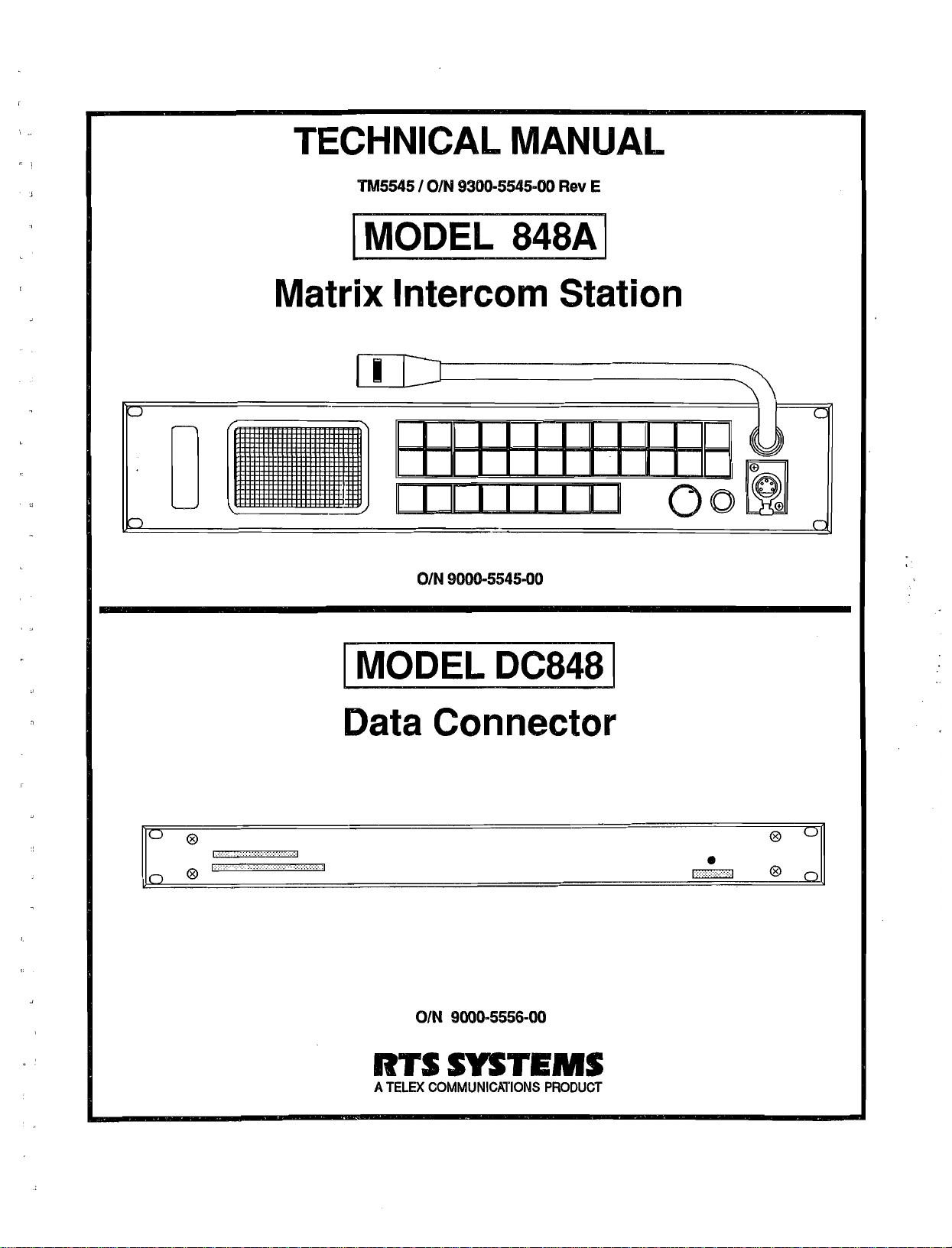
Matrix
Data Connector
Intercom
O/N 9000-5545-00
Station
81N 9000-5556-08
RTS
A
TELEX COMMUNICATIONS PRODUCT
SYSTEMS
Page 2
PROPRIETARY NOTICE
UNPACKING AND INSPECTION
The information and design disclosed herein were
originated by and are the property of RTS Systems. RTS
S ystemsreserves all patent, proprietary design, manufactur-
and
ing, reproduction, use
article disclosed therein, except to the extent rights
expressly granted
COPYRIGHT NOTICE
Copyright 1991 by RTS Systems, Burbank, California,
U.S .A. All rights reserved. Reproduction in whole or in part
without written permission from RTS Systems is prohibited.
PATENT NOTICE
This product contains and uses a design embodied
States Patent No. 4,358,644: "BILATERAL CURRENT
SOURCE FOR A MULTI-TERMINAL INTERCOM".
This design employs a bilateral current source operated as
a two-wire to four-wire converter.
Technical Manual,
Model 848A Matrix Intercom System
Model DC848 Data Connector
This manual is published by the Engineering Department of
RTS Systems, which is responsible for its contents.
Address communications regarding this manual to:
Sales Engineer
RTS Systems
The Center at Burbank Airport
2550 Hollywood Way, Suite 207
Burbank, CA 91505 USA
Unpacking Information ii
Warranty iii
Return Shipping Instructions
Description and Specifications
Installation
Operating Instructions
Theory of Operation .4- 1
Maintenance, Test Procedures
&
Troubleshooting 5-1
to
TM5545
QUICK
tice
..............
..............
sales rights thereto, and to any
others.
in
United
TABLE
.............
OF
CONTENTS
...........
ii
ii
.........
.......
......
.........
iii
1-1
2-1
3-1
.........
..........
are
Immediately upon receipt of the equipment, inspect the
shipping container and the contents carefully for any dis-
crepancies or damage. Should there be any, notify the
and
freight company
The Model 848A Matrix Intercom Station shipping con-
tainer should contain the following components:
Ordering Number 9000-5545-00
RTS Systems
atlr
1
1
1
17 2006-0014-00 Terminal Connectors,
1
The Model DC848 Data Connector shipping container
should contain the following components:
Ordering Number 9000-5556-00
Qty
1
1
1
"Warning:
radio frequency energy, and if not installed and used in
accordance with the instruction manual, may cause inter-
ference to radio communications. It has been tested and
found to comply with the limits for a Class A computing
device pursuant to Subpart
are designed to provide reasonable protection against such
interference when operated in a commercial environment.
Operation of this equipment
cause interference in which case the user, at his own ex-
pense, will be required to take whatever measures may be
required to correct the interference."
-
9010-5545-00 Model 848A
9300-5545-00 Technical Manual
9020-4979-00 Power Supply Assembly
2006-0075-00 15-pin connector
RTS Systems
Part
Number Desctipti~
9000-5556-00 Model DC848
9300-5545-00 Technical ~anuh
9020-4979-00 Power Supply Assembly
This equipment generates, uses,
the dealer at once.
pin crimp
locking ramp
NOTICE
J
of Part
15
ofFCC Rules, which
in a residential area is likely to
with
.
'4
?\%
and
can radiate
-Page
ii-
Page 3
RTS SYSTEMS' LIMITED WARRANTY
RETURN SHIPPING INSTRUCTIONS
The products of RTS Systems are warranted to
defects in materials and workmanship for a period of three
years from the date of sale.
RTS Systems sole obligation during the warranty period is
to provide, without charge, parts and labor necessary
remedy covered defects appearing
prepaid to RTS Systems. This warranty does not cover any
defect, malfunction or failure caused beyond the control of
RTS Systems, including unreasonable or negligent opera-
tion, abuse, accident, failure to follow instructions in the
Service Manual or the User Manual, defective or improper
associated equipment, attempts at modification and repair
not authorized by RTS Systems, and shipping damage.
Products with their serial numbers removed or effaced
not covered by this warranty.
To obtain warranty service, follow the procedures entitled
"PROCEDURE FOR RETURNS" and "SHIPPING TO
MANUFACTURER FOR REPAIR
This warranty is the sole and exclusive express warranty
given with respect toRTS Systemsproducts. It is therespon-
sibility of the user to determine before purchase that this
product is suitable for the user's intended purpose.
ANY AND ALL IMPLIED WARRANTIES, INCLUD-
ING THE IMPLIED WARRANTY OF MERCHAN-
TABILITY ARE LIMITED TO THE DURATION
THIS EXPRESS LIMITED WARRANTY.
NEITHER RTS SYSTEMS NOR THE DEALER WHO
SELLS RTS SYSTEMS' PRODUCTS IS LIABLE FOR
INCIDENTAL OR CONSEQUENTIAL DAMAGES
OF
ANY KIND.
in
OR
be
free
from
to
products returned
are
ADJUSTMENT".
OF
Procedure For Returns
If a repair is necessary, contact the dealer where this unit
was purchased.
If
repair through the dealer is not possible, contact the
Customer Service Department, located at the factory by
telephone, as directed below, to obtain a RETURN
AUTMORIZATION NUMBER.
DO NOT RETURN ANY EOUIPMENT DIRECTLY
TO THE FACTORY WITHOUT FIRST OBTAINING
A
RETURN AUTHORIZATION NUMBER.
Be prepared to provide the company name, address, phone
number, a person to contact regarding the repair, the type
and quantity of equipment, a description of the problem and
the serial
Questions regarding returns for repair should be directed to:
SHIPPING TO MANUFACTURER FOR REPAIR
OR ADJUSTMENT
All shipments of RTS Systems equipment should be
via United Parcel Service or the best available shipper. The
equipment should
if that
and of adequate size. If a substitute container is used, the
equipment should
at least four inches of excelsior or similar shock-absorbing
material. All shipments should be directed to the attention
of the Customer Service Department and must include the
Return Authorization Number.
number(s).
Customer Service Department
RTS Systems
The Center at
2550 Hollywood Way, Suite 207
Burbank, CA
Telephone: (818) 566-6700
Telex: 194855
Telefax: (818) 843-7953
Burbank Aiiort
9
1505 U.S.A.
a
be
shipped in the original packing carton;
is
not available, use any suitable container that is rigid
be
wrapped in paper and surrounded with
Upon completion of any repair the equipment will be
returned collect via United Parcel Service or specified ship-
per.
Page 4
Model
TECHNICAL
848A
Matrix Intercom Station / Model
MANUAL
DC848
Data Concentrator
TD OTHER
TW
STATIONS (IF USED);
PSWPS31
INTERCOM
POWER
SUPPLY.
Model
848A
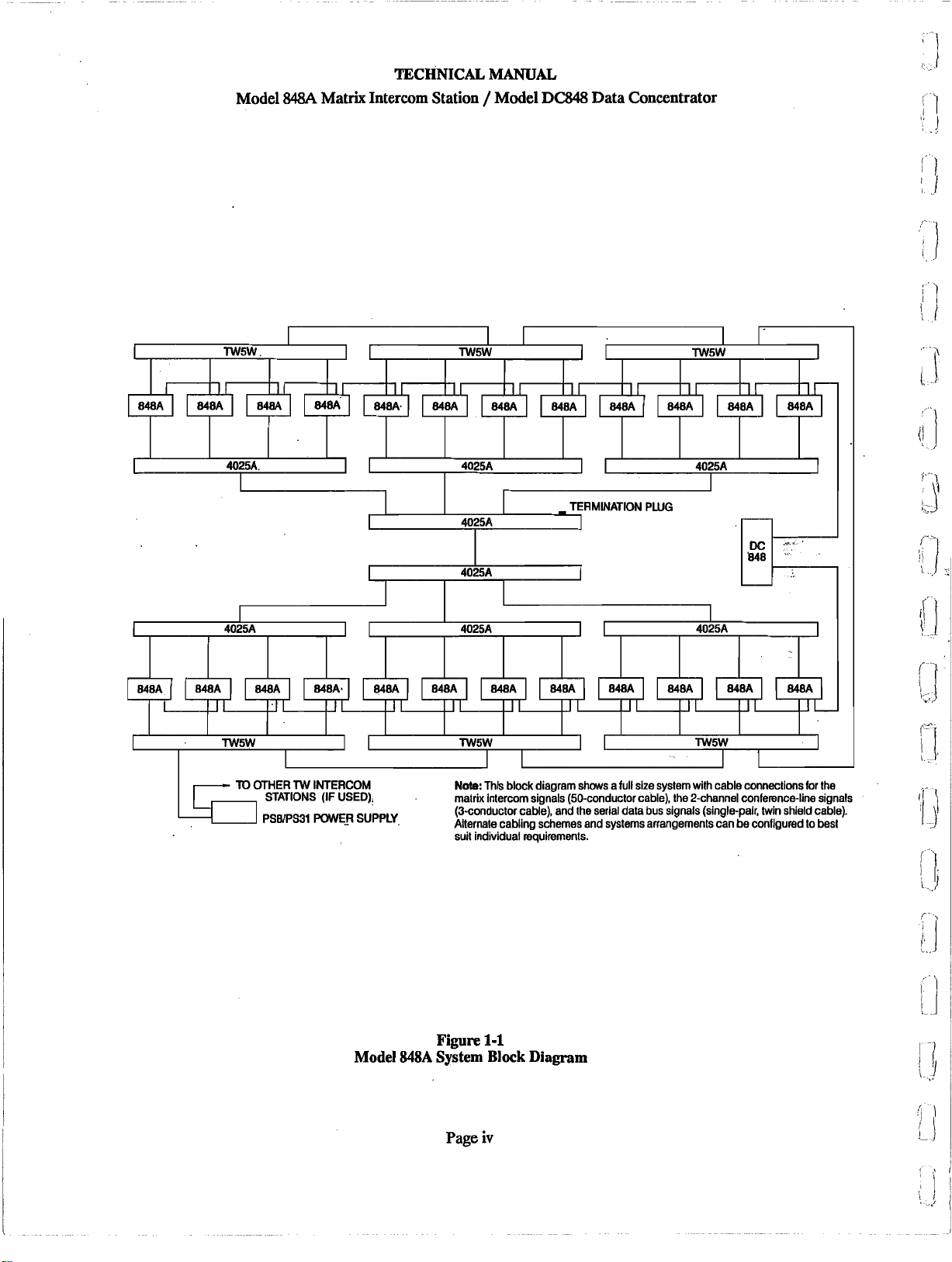
Note:
This block diagram shows a full size system with cable connections for the
matrix intercom signals (50-conductor cable), the Pchannel conference-line signals
(3-conductor cable), and the serial data bus signals (single-pair, twin shield cable).
Alternate cabling schemes and systems arrangements can
suit individual requirements.
Figure
System
Page
1-1
Block
iv
Diagram
be
configured to besl
Page 5
Model
TECHNICAL MANUAL
848A
Matrix Intercom Station / Model DC848 Data Concentrator
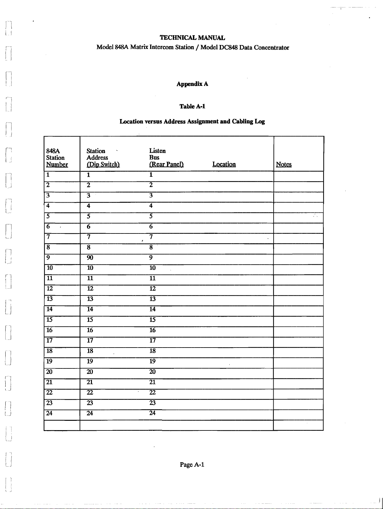
Appendix A
Table A-d.
Location versus Address Assignment and Cabling
Log
Page
A-1
Page 6
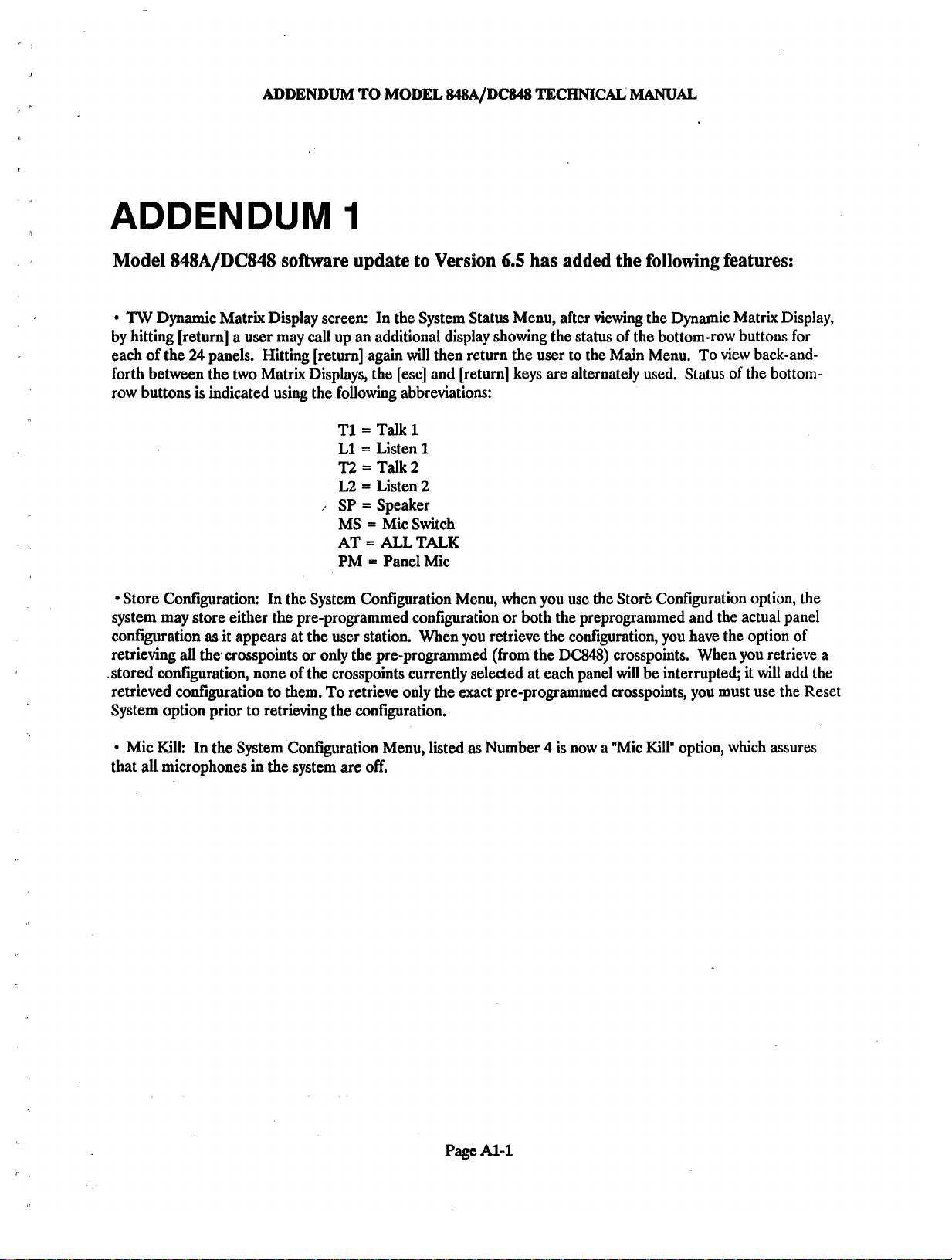
ADDENDUM TO MODEL 848A/DC848
TECHNICAL
MANUAL
ADDENDUM
Model
by hitting [return] a user may
each of the
forth between the two Matrix Displays, the [esc] and [return] keys are alternately used. Status of the bottom-
row buttons
Store Configuration: In the System Configuration Menu, when you use the Store Configuration option, the
system may store either the pre-programmed configuration or both the preprogrammed and the actual panel
configuration
retrieving
.stored configuration, none of the crosspoints currently selected at each panel
retrieved ~o~guration to them. To retrieve only the exact pre-programmed crosspoints, you must use the Reset
System option prior to retrieving the configuration.
8slSA/DC848
TW
Dynamic Matrix Display screen: In the System Status Menu, after viewing the Dynamic Matrix Display,
24
panels. Hitting [return] again will then return the user to the Main Menu. To view back-and-
is
indicated using the following abbreviations:
as
it appears at the user station. When you retrieve the conftguration, you have the option of
all
the. crosspoints or only the pre-programmed (from the DC848) crosspoints. When you retrieve a
software update to Version
1
call
up
an
additional display showing the status of the bottom-row buttons for
=
Talk
T1
L1 = Listen
T2
=
Talk 2
L2
=
Listen
/
SP = Speaker
=
MS
=
ALL
AT
PM = Panel Mic
1
1
2
Mic Switch
TALK
6.5
has added the following features:
will
be interrupted; it
will
add the
Mic Kill: In the System Configuration Menu, listed as Number
that all microphones
in
the system are off.
Page Al-l
4
is
now a "Mic
Kill"
option, which assures
Page 7
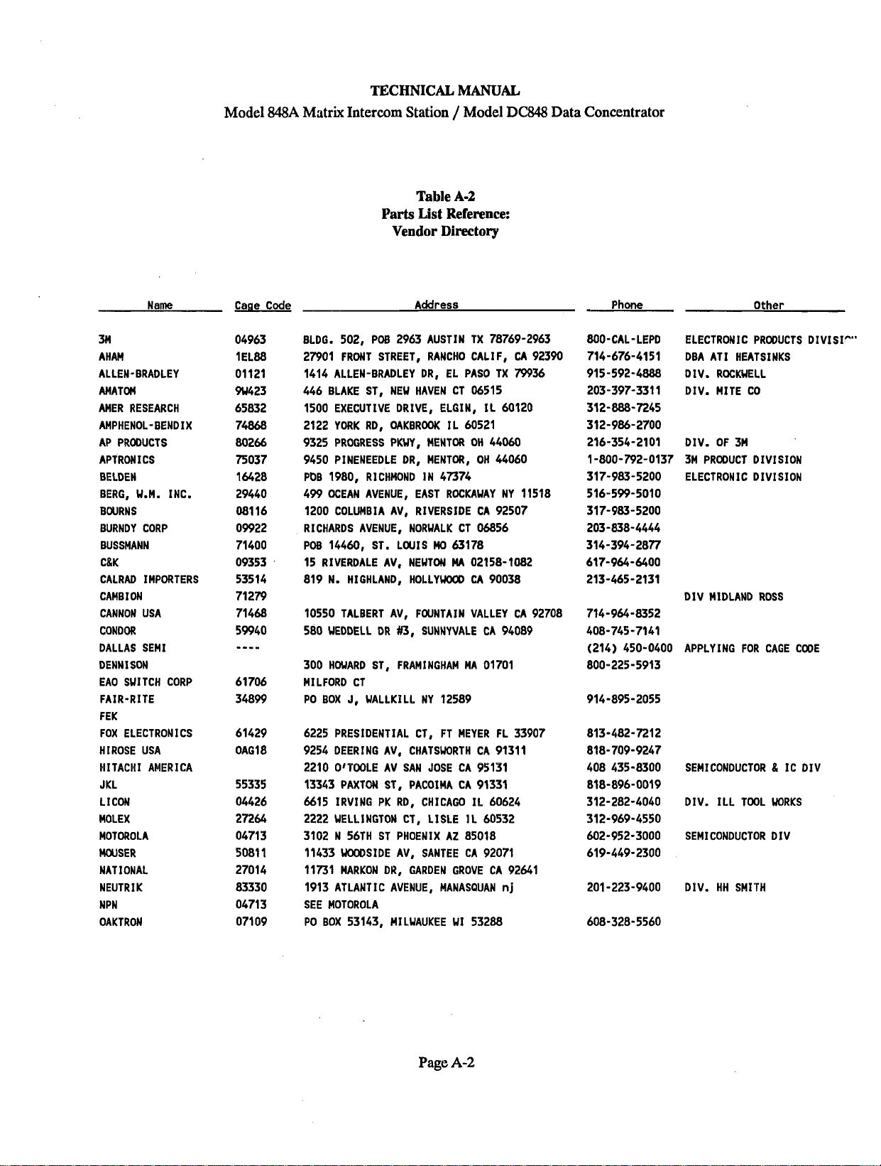
TECHNICAL MANUAL
Model 848A Matrix Intercom Station / Model D6848 Data Concentrator
Table
A-2
Parts
List
Reference:
Vendor Directory
Name
3M
AHAM
ALLEN-BRADLEY
AMATOM
AMER RESEARCH
AMPHENOL-BENDIX
AP PRODUCTS
APTRON
I
CS
BELDEN
BERG, U.M. INC.
BOURNS
BURNDY CORP
BUSSMANN
C&K
CALRAD IMPORTERS
I
ON
CAMB
CANNON USA
CONDOR
DALLAS SEMI
DENNISON
EAO SUITCH CORP
FAIR-RITE
F EK
FOX ELECTRONICS
HIROSE USA
HITACHI AMERICA
JKL
LICON
MOLEX
MOTOROLA
MWSER
NATIONAL
I
K
NEUTR
NPN
OAKTRON
Cage Code
Address
BLDG. 502, POB 2963 AUSTIN TX 78769-2963
27901
FRONT STREET, RANCHO CALIF,
1414 ALLEN-BRADLEY DR, EL PAS0 TX
446 BLAKE ST, NEW HAVEN CT 06515
1500 EXECUTIVE DRIVE, ELGIN,
2122 YORK RD, OAKBROOK IL 60521
9325 PROGRESS PKWY, MENTOR OH 44060
9450 PINENEEDLE DR, MENTOR, OH 44060
PDB
1980,
RICHMOND IN 47374
499 OCEAN AVENUE, EAST ROCKAUAY NY 11518
1200 COLUMBIA AV, RIVERSIDE CA 92507
RICHARDS AVENUE, NORWLK CT 06856
W
POB 14460, ST. LWlS
15 RIVERDALE AV, NEWTON
819
1.
HIGHLAND, HOLLYWOOD
10550 TALBERT AV, FOUNTAIN VALLEY CA 92708
580 UEDDELL
300 HOWARD ST, FRAMINGHAM MA 01701
MILFORD CT
PO BOX
6225 PRESIDENTIAL CT, FT MEYER FL 33907
9254 DEERING AV, CHATSUORTH CA
2210 OfVOOLE AV SAN JOSE CA 95131
13343 PAXTON ST, PACOIMA CA
6615 IRVING PK RD, CHICAGO IL 60624
2222 WELLINGTON CT, LISLE IL 60532
3102 N 56TH ST PHOENIX AZ 85018
11433
11731
1913
SEE MOTOROLA
PO BOX 53143, MILUAUKEE UI 53288
DR
#3,
J,
UALLKILL NY 12589
WOODSIDE AV, SANTEE CA 92071
MARKON DR, GARDEN GROVE CA 92641
ATLANTIC AVENUE, MANASQUAN
63178
MA
02158-1082
CA
SUNNYVALE CA 94089
IL
90038
91311
91331
CA
92390
79936
60120
n
j
Phone
Other
ELECTRONIC PRODUCTS DIVISI""
AT1 HEATSINKS
DBA
DIV. ROCKUELL
DIV. MITE CO
DIV. OF 3M
3M PRODUCT DIVISION
ELECTRONIC DIVISION
DIV MIDLAND ROSS
APPLYING FOR CAGE CODE
SEMICONDUCTOR
DIV. ILL TOOL WORKS
SEMICONDUCTOR DIV
DIV. HH SMITH
&
IC DIV
Page
A-2
Page 8
Model
TECHNICAL
$48A
Matrix Intercom Station / Model DC848 Data Concentrator
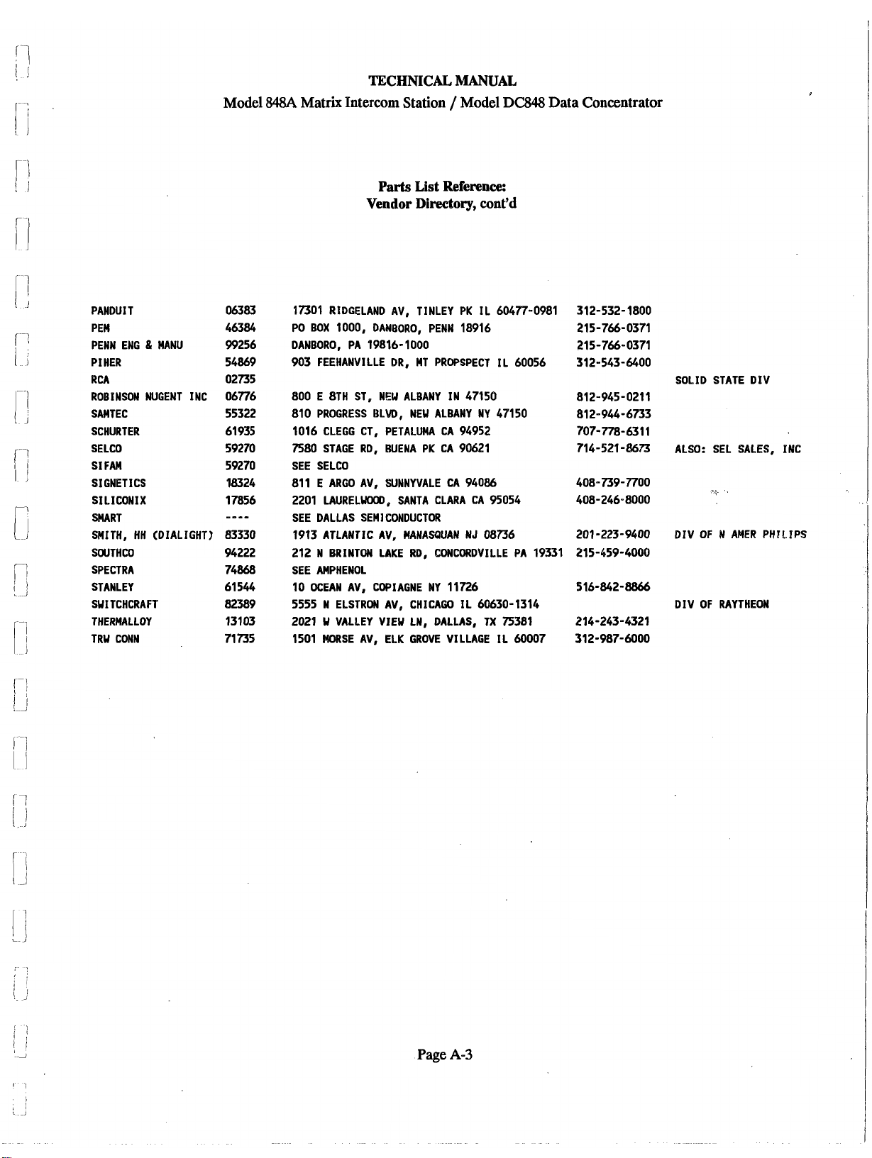
Parts
Vendor Directory,
MANUAL
List Reference:
cont'd
PANDUI T
PEW
PENN ENG
PIHER
RCA
ROBINSON NUGENT INC
SAMTEC
SCHURTER
SELCO
SIFAM
SIGNETICS
SILICONIX
SMART
SMITH, HH (DIALIGHT)
SWTHCO
SPECTRA
STANLEY
SWITCHCRAFT
THERMALLOY
TRW CONN
&
MANU
17301 RIDGELAND AV, TINLEY PK IL 60477-0981
PO BOX 1000, DANBORO, PENN
DANBORO, PA
903
FEEHANWILLE DR, MT PROPSPECT IL 60056
800 E 8TH ST, NEU ALBANY IN 47150
810
PROGRESS BLW, NEW ALBANY NY 47150
1016
CLEGG CT, PETALUMA CA 94952
7580
STAGE RD, BUENA PK CA 90621
SEE SELCO
811
E ARGO AV, SUNNYVALE CA 94086
2201 LAURELUOOD, SANTA CLARA CA 95054
SEE DALLAS SEMICONDUCTOR
1913
ATLANTIC AV, MANASQUAN NJ 08736
212 N BRINTON LAKE RD, CONCQRDVILLE PA
SEE AMPHENOL
10
OCEAN AV, COPIAGNE NY
5555 N ELSTRON AV, CHICAGO IL 60630-1314
2021
W VALLEY VIEW LN, DALLAS, TX 75381
1501 MORSE AV, ELK GROVE VILLAGE IL
19816-
1000
18916
19331
11726
60007
312-532-1800
215-766-0371
215-766-0371
312-543-6400
SOLID STATE DIV
812-945-0211
81
2-944-6733
707-778-631
714-521-8673 ALSO: SEL SALES, INC
516-842-8866
214-243-4321
31
2-987-6000
1
DIV OF
RAYTHEON
Page
A-3
Page 9
Model
TECHNICAL MANUAL
848A
Matrix Intercom Station / Model
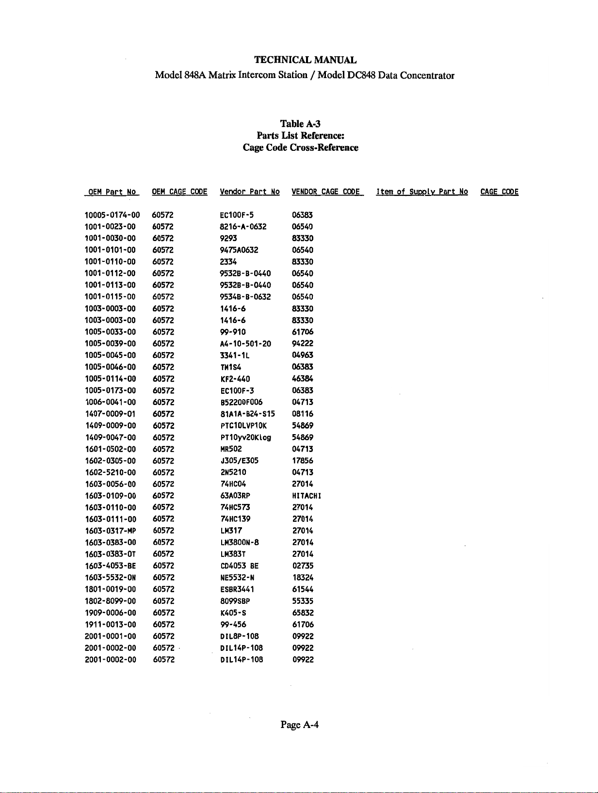
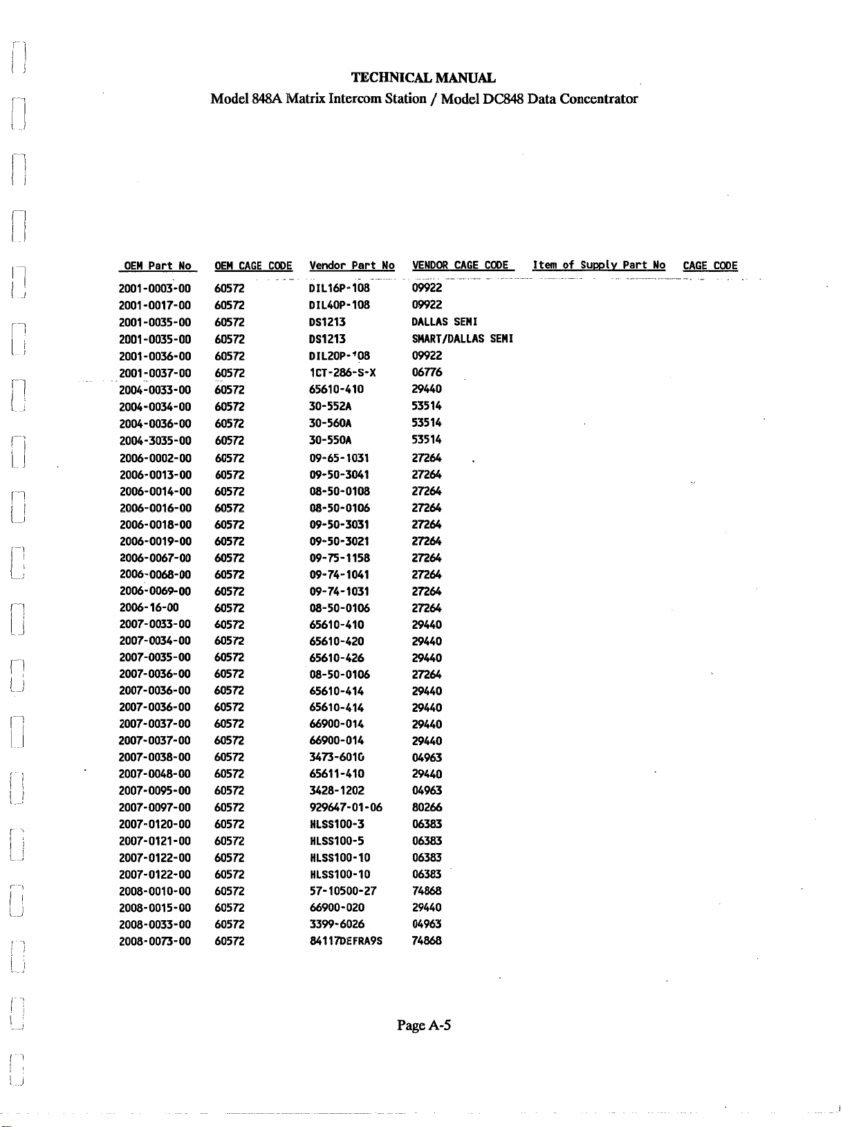
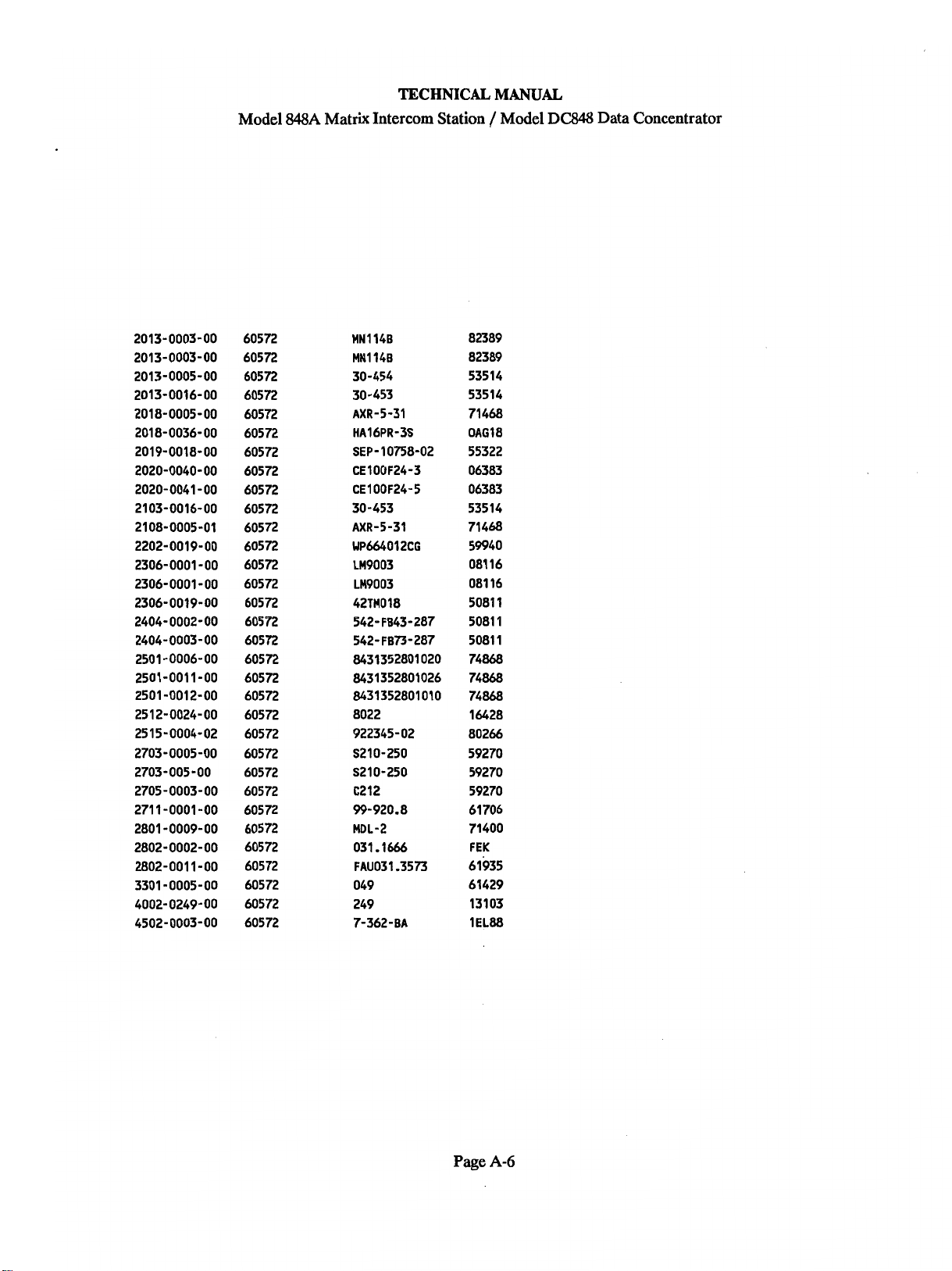
Table
Parts List Reference:
Cage Code Cross-Reference
A-3
DC848
Data Concentrator
OEM Part
No
OEM CAGE CODE Vendor Part No
EC100F-5
8216-A-0632
9293
9475A0632
2334
95328-8-0440
95328-8-0440
95348-
99-910
A4-10-501-20
3341-1L
THlS4
KF2-440
EC100F-3
852200F006
81AlA-824-S15
PTClOLVPlOK
PTlOyv20K
MR502
J305/E305
2N5210
74HC04
63A03RP
74HC573
74H6139
LM317
LM3800N-8
LM383T
CD4053 BE
NE5532-N
ESBR3441
8099SBP
K405
99-456
DIL8P-108
DIL14P-108
DIL14P-108
1416-6
1416-6
-
S
8-0632
Log
VENDOR
06383
06540
83330
06540
83330
06540
06540
06540
83330
83330
61 706
94222
04963
06383
CAGE
46384
06383
04713
08116
54869
54869
04713
17856
04713
27014
HITACHI
27014
27014
27014
27014
27014
02735
18324
61544
55335
65832
61706
09922
09922
09922
CODE
Item
of
Sum~y Part
No
CAGE CODE
Page
A-4
Page 10
Model
TECHNICAL
848A
Matrix Intercom Station / Model DM Data Concentrator
MANUAL
OEM Part No OEM
60572
60572
60572
60572
60572
60572
60572
60572
60572
60572
60572
60572
60572
68572
60572
60572
60572
60572
60572
60572
60572
60572
60572
60572
60572
60572
60572
60572
60572
60572
60572
60572
60572
60572
60572
60572
60572
60572
60572
60572
CAGE
Vendor Part No
CODE
.
.-
~1~16~-108-
DIL40P- 108
DS1213
DS1213
DIL20P-'08
1CT-286-S-X
65610-410
30-552A
30-560A
30-550A
09-65-1031
09-50-3041
08-50-0108
08-50-0106
09-50-3031
09-50-3021
09-75-1158
09-74-1061
09-74-1031
08-50-0106
65610-410
65610-420
65610-426
08-50-0106
65610-414
65610-414
66900-014
66900-014
3473-6016
6561 1-410
3428- 1202
929647-01 -06
HLSS100-3
HLSS100-5
HLSS100-10
HLSS100-10
57- 10500-27
66900-020
3399-6026
861178EFRA9S
VENDOR CAGE CODE
09922
-
09922
DALLAS SEMI
SMART/BALLAS SEMI
09922
06776
29440
535 14
535 14
53514
27264
27264
27264
27264
27264
27264
27264
27264
27264
27264
29440
29440
29440
27264
29440
29440
29440
29440
04963
29440
04963
80266
06383
06383
06383
06383
74868
29440
04963
74860
I
tern
of
-.
-
.
-
--
Supply
Part No CAGE CODE
-
--
-- - -
-
.
Page
8-5
Page 11
Model
TECHNICAL
848A
Matrix Intercom Station / Model
MANUAL
DC848
Data Concentrator
MN114B
MN114B
30-454
30-453
AXR-5-31
HA16PR-3s
SEP- 10K8-02
CE100F24-3
CE100F24-5
30-453
AXR-5-31
WP664012CG
LM9003
LM9003
42TM018
542- FB43-287
542-FB73-287
8431352801 020
8431352801026
8431352801010
8022
922345-02
S210-250
S210-250
C212
99-920.8
MDL-2
031.1666
FAUO3l .3573
049
249
7-362
-
BA
82389
82389
535 14
53514
71468
0ag18
55322
06383
06383
53514
71468
59940
081 16
081 16
5081 1
5081
1
5081 1
74868
74868
74868
16428
80266
59270
59270
59270
61 706
71400
FEK
61935
61429
13103
1e188
Page
A-6
Page 12
Model
TECHNICAL MANUAL
848A
Matrix Intercom Station / Model DC848 Data Concentrator
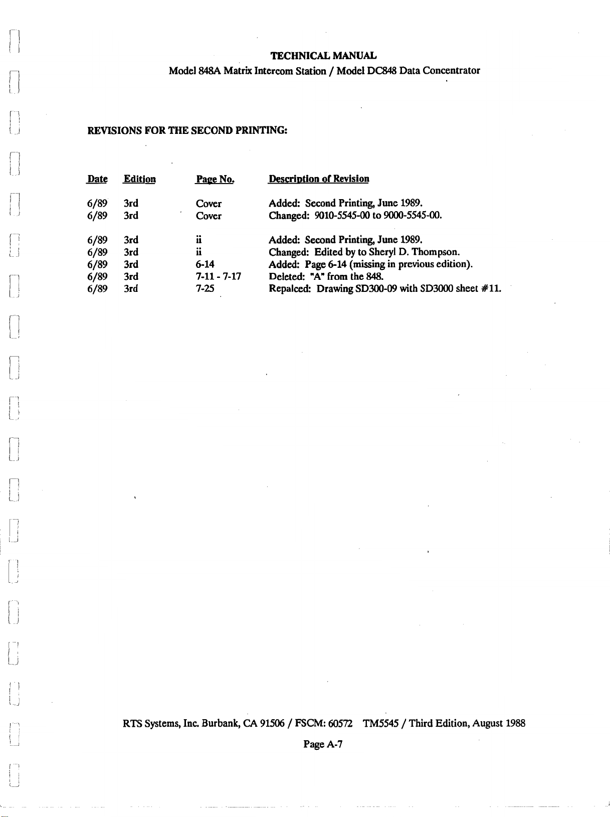
REVISIONS FOR THE
Date Edition
-
6/89 3rd Cover Added: Second Printing, June 1989.
6/89 3rd Cover Changed: 9010-5545-00 to 9000-5545-00.
6/89 3rd
6/89 3rd
6/89 3rd
6/89 3rd
6/89 3rd
SECOND
Pave No.
ii Added: Second Printing, June 1989.
ii Changed: Edited
6-14 Added: Page 6-14 (missing in previous edition).
7-11
7-25 Repalced: Drawing SD300-09 with
PRINTING:
of
Descriotion
-
7-17 Deleted: "A" from the
Revision
by
to Sheryl
848.
D.
Thompson.
SD3000
sheet
#11.
RTS Systems,
Inc.
Burbank,
CA
91506 / FSCM: 60572 'I'M5545 / Third Edition, August
Page A-7
1988
Page 13
TECHNICAL
MANUAL
Model
SECTION
1.1
1.1.1
(See Figure
1:
DESCRIPTION & SPECIFICATIONS channel. The conference line channels and point-to-
DESCRIPTION
System and Model WA Description
1-1,
Model
848A
Matrix Intercom Station / Model DC848 Data Concentrator
848A
System Block Diagram)
Point-to-Point Matrix Intercom
A
Model
tions, connecting cables,
848A
system consists of Model
and,
848A
sta-
optionally, a Model
DC848 Data Concentrator and data terminal (a per-
sonal computer
Each
848A is
system which
as
24
stations. Each station
can
be
used as a terminal).
a station in a point-to-point intercom
can
have
as
few
as 2 stations or
can
talk to a single station
as
many
or combination of other stations.
Any configuration of multiple stations
called a matrix. In the matrix, up to
in
this system is
12
separate
conversations may be in progress at any time. Each
conversation requires two talk paths to two listen
buses. Each talk path is the listen bus for one of the
twenty four stations.
point channels may
848A
Model
Each Model
be
used at the same time.
Station Micro~rocessor
848A
is equipped with an internal micro-
processor which provides electronic switch-action
link
(momentary /latching), and a
to the Model
DC848 Data Concentrator. If the power fails, the
station remembers its settings. The settings are re-
stored when the power returns.
1.12
System
Connecting a Model DC848 to the
and
Model DC848 Description
848A
system adds
these functions to the system:
1.
CallTally
2.
Received Call Stacking
3.
Remote-Control / Programming Capabilities
1.
The Call Tally function means that the pushbutton
corresponding to the calling station
will
flash on the
called station's panel, telling the operator visually
which station is calling.
In a typical operating example, a user (caller) chooses
the station he wishes to talk to by pressing the push-
button corresponding to the called station. The
can
station
station
same listen bus
then hear the calling station. No other
can
hear this message unless it shares the
as
the called station or more than one
called
station has been called by the caller.
The called station answers tbe calling station by
pressing the pushbutton corresponding to the calling
station. If the
848A
system includes a DC848 Data
Concentrator, a call may also be answered by pressing
call
the
answer pushbutton, which is marked with the
station's own number with a colored insert. When the
communication is completed, each station releases
and the connection is broken.
A station
can
talk to all other stations at once, by
pressing the ALL TALK button.
Conference Intercom
TW
Each Model 848A station has two
Intercom con-
ference-line channels, which either connect to an RTS
TW
Systems
Intercom System, or interconnect 848A
stations for two channels of isolated conference inter-
com. These conference lines, Channels
1
&
2,
have
front panel TALK and LISTEN switches for each
2.
The Received Call Stacking function means that
station
will
can
is
called by several stations, the called station
make a queue of the calling stations. This queue
be answered in succession by pressing the Call
if
Answer pushbutton.
3.
The Remote Control / Programming Capabilities
allow the Model
848A
to be controlled and
programmed remotely by connecting either a
computer or a "dumb" terminal to the Model DC848
data bus. The software for the 848A and
DC848
lets
each station be programmed individually in real-time.
Features programmable with this setup include:
a. Forced Crosspoint. Sets up a one way voice
communication path between two stations.
b. Inhibit Crosspoint. Inhibits voice path and tally,
one way, between two stations.
(Continued)
a
Page
1-1
Page 14
TECHNICAL
MANUAL
Model
Panel Switch Action (Latch Disable). Sets the
c.
switch action for an individual panel switch,
either momentary only or both momentary
and latching.
Hands-Free Answer (Auto
d.
e.
f.
g.
h.
station
automatically to allow hands-free answering
"Instant
'!Instant Sveaker OQ".
Auto Talh,
Panel Grou~ Assignments. Assigns panels into
preset groups.
is
Mic
Onw.
turn on automatically whenever a call
originated.
turn on automatically whenever the station
is
called.
Flash
pushbutton will flash when called. Can
set from a 10-second minimum to a
second maximum in
84&4
Matrix Intercom Station / Model DC848 Data Con=nt,rator
Reci~rocal). When a
called, 'its microphone turns on
When set, the microphone
When set, the speaker will
Erne.
Adjusts the time the
10
second increments
in a system with a DC848 connected. This button
also
the station address.
All
pushbuttons have two levels of brightness.
activated button has a higher brightness.
The third row of eight pushbutton switches are
follows:
1
TALK INTERCOM CH.l
1
LISTEN INTERCOM CH.l
TALK
MIC
(selects panel microphone when
ON or headset microphone when
or headset, whichever
PANEL MIC switch)
848A
Connections, Inputs and Outputs
will
is
be
60-
COW
CONF
COW 2 TALK INTERCOM CH.2
CONF 2 LISTEN INTERCOM CH.2
ALL
PANEL
SPKR ON (spe OT er on)
MIC ON (enables mic circuit in either panel mic
1.1.4
Model
Front Panel
is
selected by
is
An
as
Dvnamic Comlink Dis~la shows stations
a.
that are connected and responding to the
DC848 data concentrator.
b.
wy
possible talk paths in current system and
their status.
j.
Svstem Confirmration. Allows preset
be
configuration to
retrieved. There
Password Security. Sets a password, preventing
k.
unauthorized use, either by terminal or
modem.
1.13
Model
The operational controls are:
Three rows of pushbutton switches, and
The master VOLUME control.
The fvst two rows of
the called point to point matrix stations, except for the
one pushbutton with a colored insert.
is
the "Call Answer" pushbutton, and
ton
848A
Operational Controls
stored into memory, and
is
also a reset choice.
24
pushbutton switches select
shows all
This
pushbut-
is
active only
Dynamic Microphone Headset Connector.
Carbon Microphone Headset Connector.
Rear Panel
POWER
AUXILIARY CONNECTION connector, 5104.
TW
EXTERNAL LOUDSPEAKER connector,
SERIAL IN connector,
SERIAL LOOP-THRU connector,
LINE
Auxiliarv Connections
The auxiliary connections on the back panel of the
Model
an unswitched microphone preamplifier output and
additional connections to the front panel.
The program input accepts a -10 dBu signal which
distributed to both the loudspeaker and the headsets.
The level
The unswitched microphone output provides a
10 dBu line level signal from the Model
microphone preamplifier.
INPUT
INTERCOM SYSTEM LINE
5602 (Conference Line, Two Channels).
connector,
5702
(12
volt ac/dc).
INPUT
51001.
51002.
CONNECTION connector,
848A
provide the user with a program input,
can
be
adjusted on the adjustment card.
5401
connector,
5204.
848A
is
-
Page 1-2
Page 15
TECHNICAL
MANUAL
Model
848A
Matrix Intercom Station / Model DC848 Data Concentrator
Additional connections for an external panel
microphone and headset. A remote microphone
switch
foortswitch,
together to
1.1.5
is
also available. Any switch, such as a
can
be used to short the two terminals
turn
on the microphone circuit.
Model 848A
Preset
(Trimpot)
Adjustments
The preset adjustment pots are located behind the
small
rectangular panel to the left of the loudspeaker.
To access the adjustments, press the rectangular
panel lightly, then release, this will unlock the panel.
Pull the panel out
far as it
will
go.
as
Behind this small panel, on a circuit board, in two
rows, are the following ten adjustment pots:
Top Row
LISTE!.N/TW
LISTEN/TW 2
1
Conference Line 1 level
Conference Line
2
level
LISTENIALL (Talk) Page level
LISTENIMATRIX
24
point-to-point stations
LISTE!.N/PGM Auxiliary program
1.1.7
Package
Model
848A
Package
848A
is
The Model
signed to fit a standard
units of space. The Model
x
19" wide
x
7"
enclosed within a metal case de-
19"
rack and occupies two rack
848A
measures 3.47"
deep and weighs
6
pounds.
high
Model DC848 Package
The Model DC848
is
enclosed within a metal case de-
signed to fit in a standard 19" rack and occupies one
rack unit of space. It
is
1.75"
high
x
19" wide x 10"
deep, and weighs 2.2 pounds.
Bottom row
BAL/1 Conference Line
1
balance
BAL/2 Conference Line 2 balance
SIDETONE Headset Sidetone Level
Adjustment
DIM Speaker Attenuation during
Mic on
MIC Microphone gain
adjustment
1.1.6
Power
Model
Each Model
to operate.
848.4
Power
848A
requires 12 volts ac at 1.4 amperes
This
power
is
supplied by an RTS
Systems Remote Power Supply--included with each
unit. The power supply comes in two types, one
is
whose mains input
second type whose mains input
117 volts/50-60 hertz ac, or a
is
2U)
volts/50-60
hertz ac.
Model DC848 Power
The Model DC848 requires 12 volts ac at
0.5
amp-
eres, and comes with its own RTS Systems Power
848A
Supply Unit normally identical to the
supply.
Page
1-3
Page 16
TECHNICAL
MANUAL
Model
1.2
SPECIFICATIONS
12.1
MODEL 848A MATRIX INTERCOM SYSTEM SPECIFICATIONS
Bus Complement
24
balanced distributed talk/listen buses
1
balanced distributed all talk bus
2
TW
Intercom 2-wire buses
Audio Level/Bus Impedance
Distributed Summine Buses
-10
dBu,
test level
-20
dBu,
nominal level
TW
Intercom Lines
dBu,
test level
0
-10
dBu,
nominal speech
Station Bridging Impedance
848A
Matrix Intercom Station/Model DC848 Data Concentrator
.
500
ohms
500
ohms
200
ohms
200
ohms
Distributed Summing Buses
TW
Intercom Lines
Distributed Summing Bus Termination
(One termination per system bus
Termination plugs may
Up to 8 stations
Up to 16 stations
Over 16 stations
Recommended Maximum System Size
Number of stations
(bus level lowered by
4
Stations per bus
(same listen channel)
Operating Distance
balanced-pair cable,
#22
gauge wire
be
with
is
usually required.
ordered from RTS Systems.)
3
dB)
12
kilohms, nominal
6
kilohms, LISTEN selected
10 kilohms, nominal
680
ohms (RTS Systems
1500
ohms (RTS Systems Part Number 9020-5189-02)
No termination
5,000
feet
Part
Number 9020-5189-01)
Page
14
Page 17
TECHNICAL
MANUAL
Model
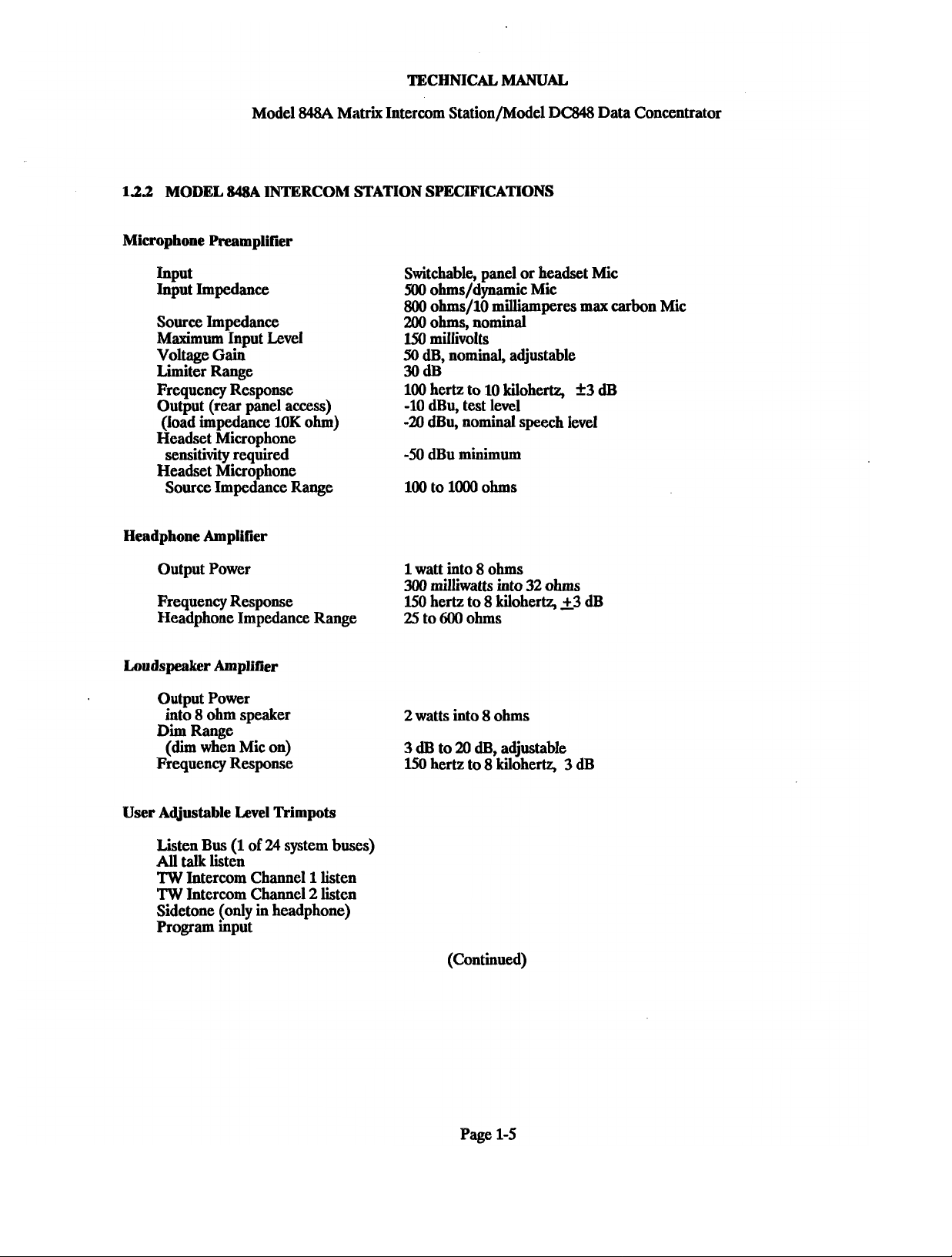
1.2.2
MODEL 848A INTERCOM STATION SPECIFICATIONS
Microphone Preamplifier
Input
Input Impedance
Source Impedance
Maximum
Voltage
Limiter Range
Frequency Response
Output (rear panel access)
(load impedance 10K ohm)
Headset Microphone
sensitivity required
Headset Microphone
Source Impedance Range
Headphone Amplifier
Input Level
Gain
848A
Matrix Intercom Station/Model
Switchable, panel or headset Mic
500
ohms/dynamic Mic
800
ohms/lO milliamperes max carbon Mic
200
ohms, nominal
150
millivolts
50
dB, nominal, adjustable
30dB
100 hertz to 10 kilohertz,
-10 dBu, test level
-21
dBu, nominal speech level
-50
dBu minimum
100 to 1000 ohms
BC848
f
Data Concentrator
3
dB
Output Power
Frequency Response
Headphone Impedance Range
Loudspeaker Amplifier
Output Power
into
8
ohm speaker
Dim
Range
(dim
when Mic on)
Frequency Response
User Adjustable Level Trimpots
Listen Bus (1
All
talk listen
TW
Intercom Channel 1 listen
TW
Intercom Channel 2 listen
Sidetone (only in headphone)
Program input
of
24
system buses)
1
watt into 8 ohms
300
milliwatts into
150
hertz to 8 kilohertz, 23 dB
25
to
600
ohms
2
watts into 8 ohms
3
dB to
20
dB, adjustable
150
hertz to 8 kilohertz,
(Continued)
32
ohms
3
dB
Page 1-5
Page 18
TECHNICAL MANUAL
Model
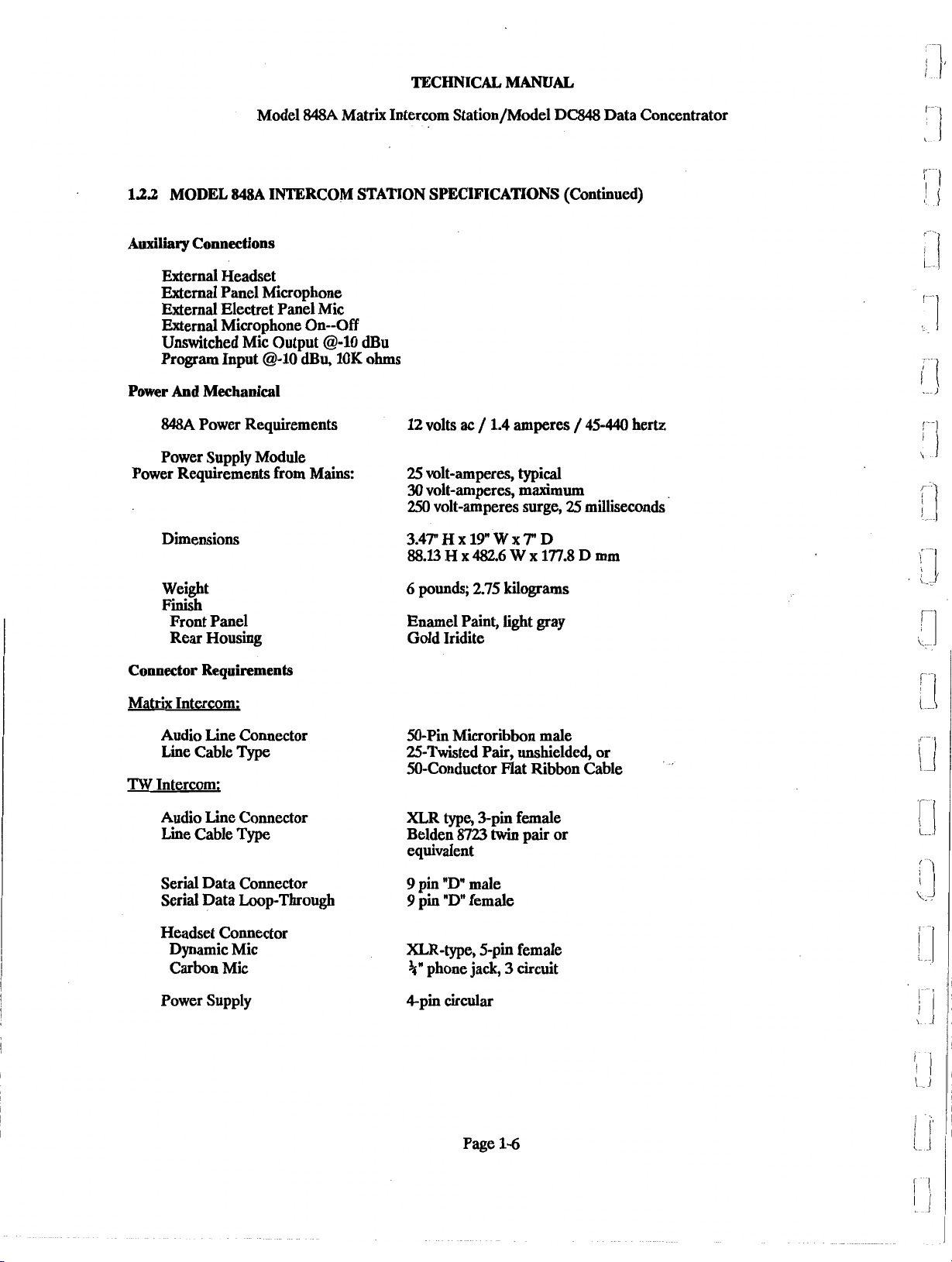
1.2.2
MODEL 848A INTERCOM STATION SPECIFICATIONS
Auxiliary Connections
External Headset
External Panel Microphone
External Electret Panel Mic
External Microphone On--Off
Unswitched Mic Output
Program Input
Power
And
Mechanical
848A
Power Requirements
Power Supply Module
Power Requirements from Mains:
Dimensions
@-I0
84814
Matrix Intercom Station/Model DC848 Data Concentrator
@-lo dBu
dBu,
10K
ohms
12
volts ac / 1.4 amperes / 45-440 hertz
25
volt-amperes, typical
30
volt-amperes, maximum
250
volt-amperes surge,
(Continued)
25
milliseconds
6
Weight
Finish
Front Panel
Rear Housing
Connector Requirements
Matrix Intercom;
Audio Line Connector
Line Cable
TW
Intercom;
Audio Line Connector
Line Cable
Serial Data Connector
Serial Data Loop-Through
Headset Connector
Dynamic Mic XLR-type, 5-pin female
Carbon Mic
Power Supply 4pin circular
Type
Type
pounds,
Enamel Paint, light gray
Gold Iridite
50-Pin Microribbon male
25-Twisted Pair, unshielded, or
50-Conductor Flat Ribbon Cable
XLR
type, 3-pin female
Belden
equivalent
9
9
+"
8723
pin
"D"
pin "D" female
phone jack, 3 circuit
2.75
twin
male
kilograms
pair or
Page 1-6
Page 19
TECHNICAL
MANUAL
Model
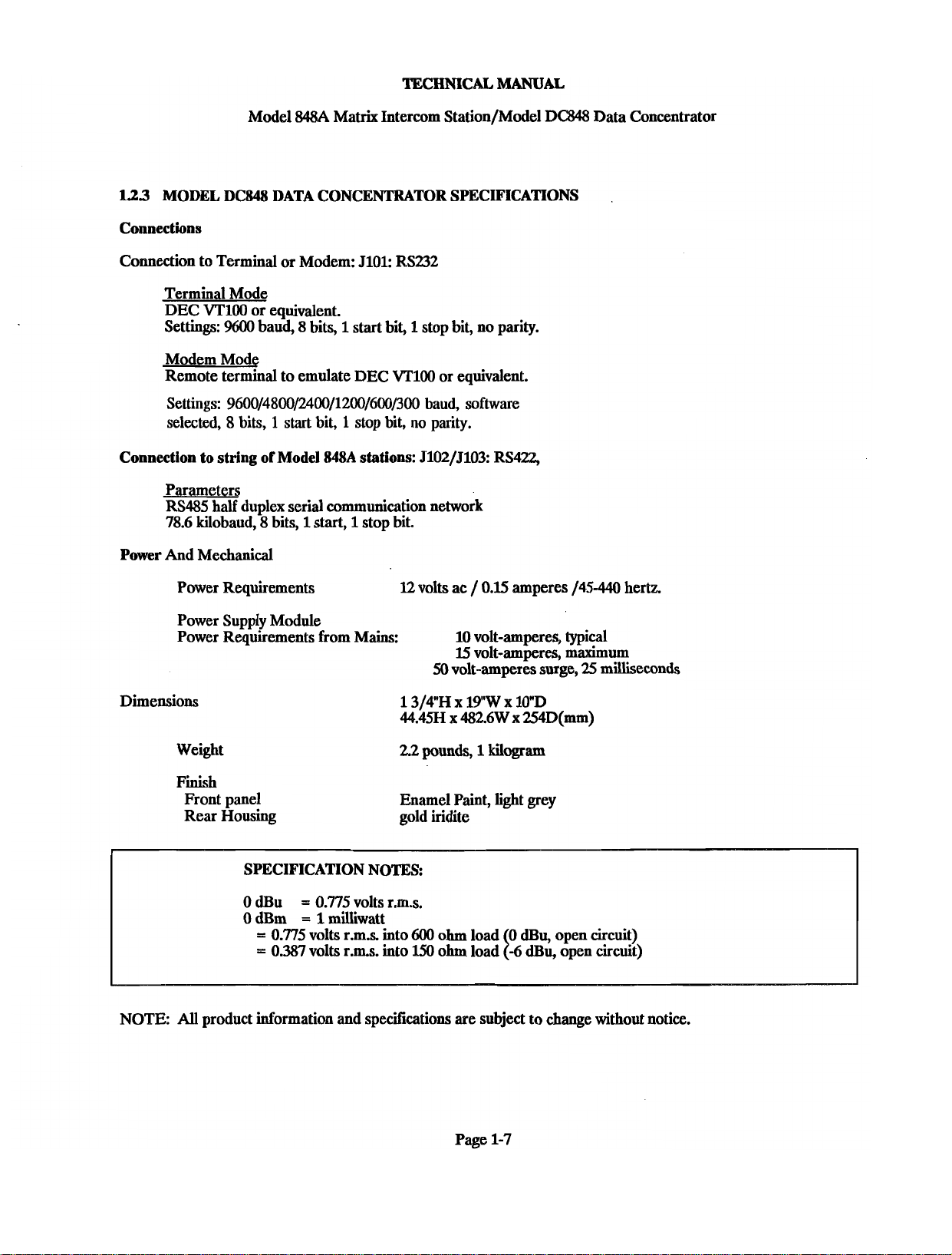
1.23
MODEL DC848 DATA CONCENTRATOR SPECIFICATIONS
Connections
Connection to Terminal or Modem: 5101:
Terminal Mode
DEC VTlOO or equivalent.
Settings:
Modem Mode
Remote terminal to emulate DEC VTlOO or equivalent.
Settings:
selected, 8 bits, 1 start bit, 1 stop bit,
Connection to string
Parameters
RS485 half duplex serial communication network
78.6 kilobaud, 8 bits,
Power And Mechanical
%00
9600/4800/2400/1200/600/300
84814
Matrix Intercom Station/Model
RS232
baud, 8 bits, 1 start bit, 1 stop bit, no parity.
baud,
software
no
parity.
of
Model 848A stations: 5102/5103: RS422,
1
start, 1 stop bit.
DC&Q8
Data Concentrator
Power Requirements
Power Supply Module
Power Requirements from Mains: 10 volt-amperes, typical
Dimensions
Weight 2.2
Finish
Front panel
Rear Housing
NOTE:
All
12 volts ac
pounds,
Enamel Paint, light grey
gold iridite
0 dBu
0 dBm
product information and specifications are subject to change without notice.
=
0.775 volts r.m.s.
=
1
milliwatt
/
0.15 amperes 145-440 hertz.
15
volt-amperes, maximum
50
volt-amperes surge,
1
kilogram
25
milliseconds
Page 1-7
Page 20
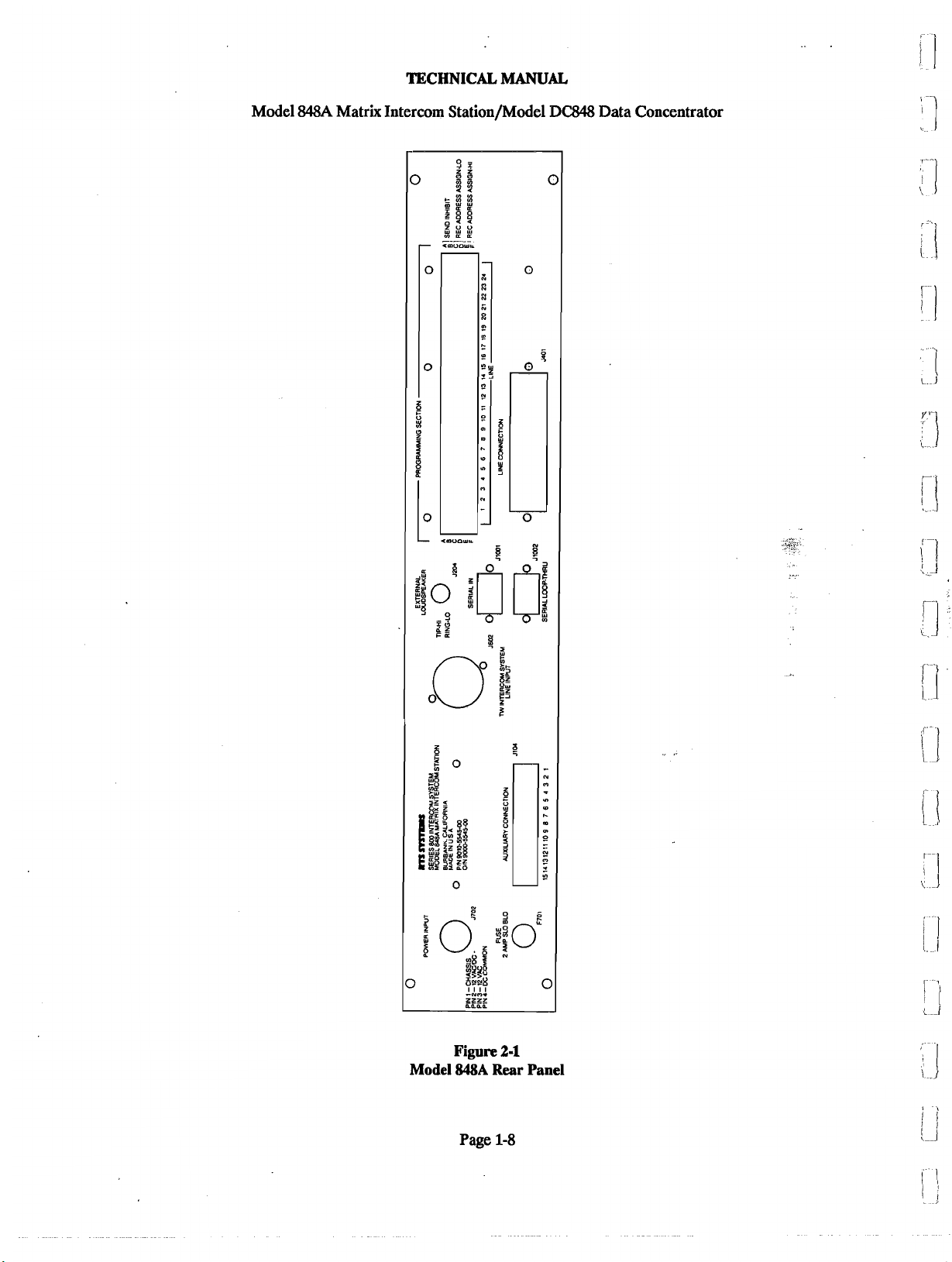
Model
TECHNICAL MANUAL
84814
Matrix Intercom Station/Model DC848 Data Concentrator
Model
Figure
848A
Page
2-1
Rear
1-8
Panel
Page 21
Model 848A
TECHNICAL MANUAL
Ma&
Intercom Station / Model DC848 Data Concentrator
SECTION
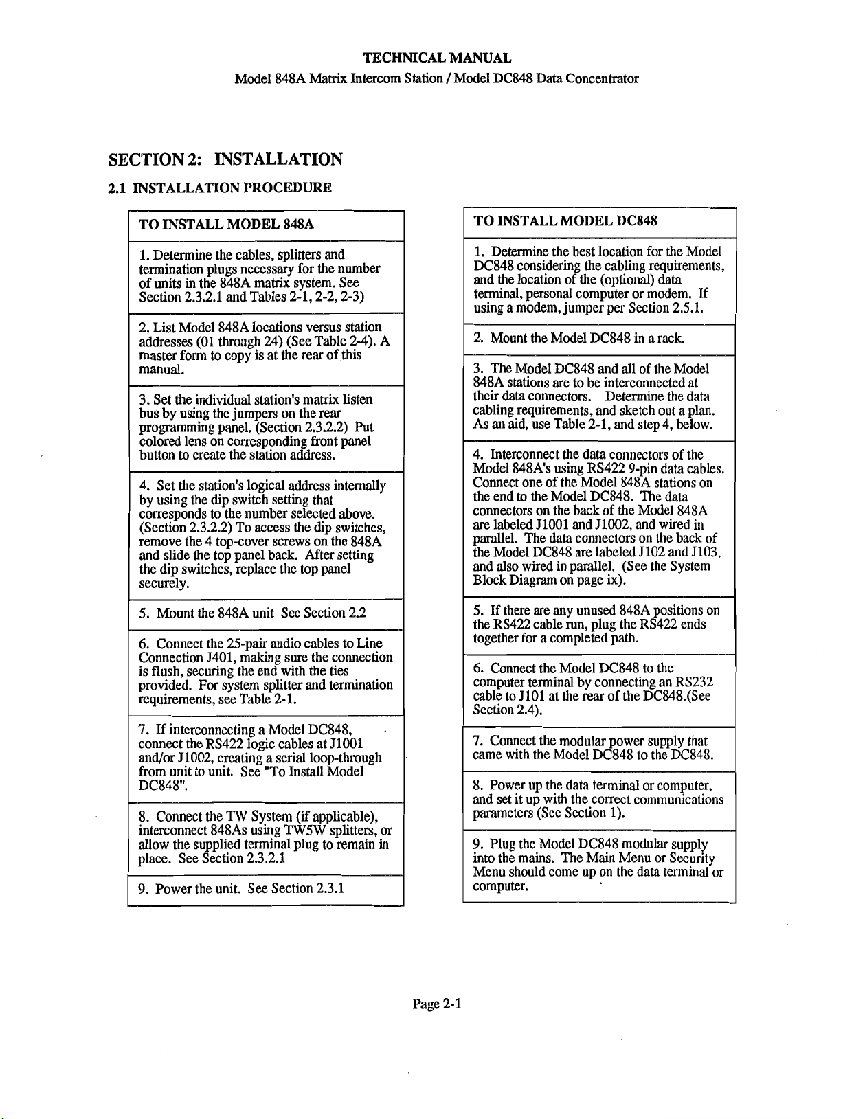
2.1
INSTALLATION PROCEDURE
2:
INSTALLATION
connectors on the back of the Model
are labeled JlOOl and 51002, and wired
parallel. The
the Model
data
DC848
connectors on the back of
are
labeled J102 and 5103,
848A
in
Page
2-
1
Page 22

TECHNICAL MANUAL
Model
848A
Matrix
Intercom Station / Model
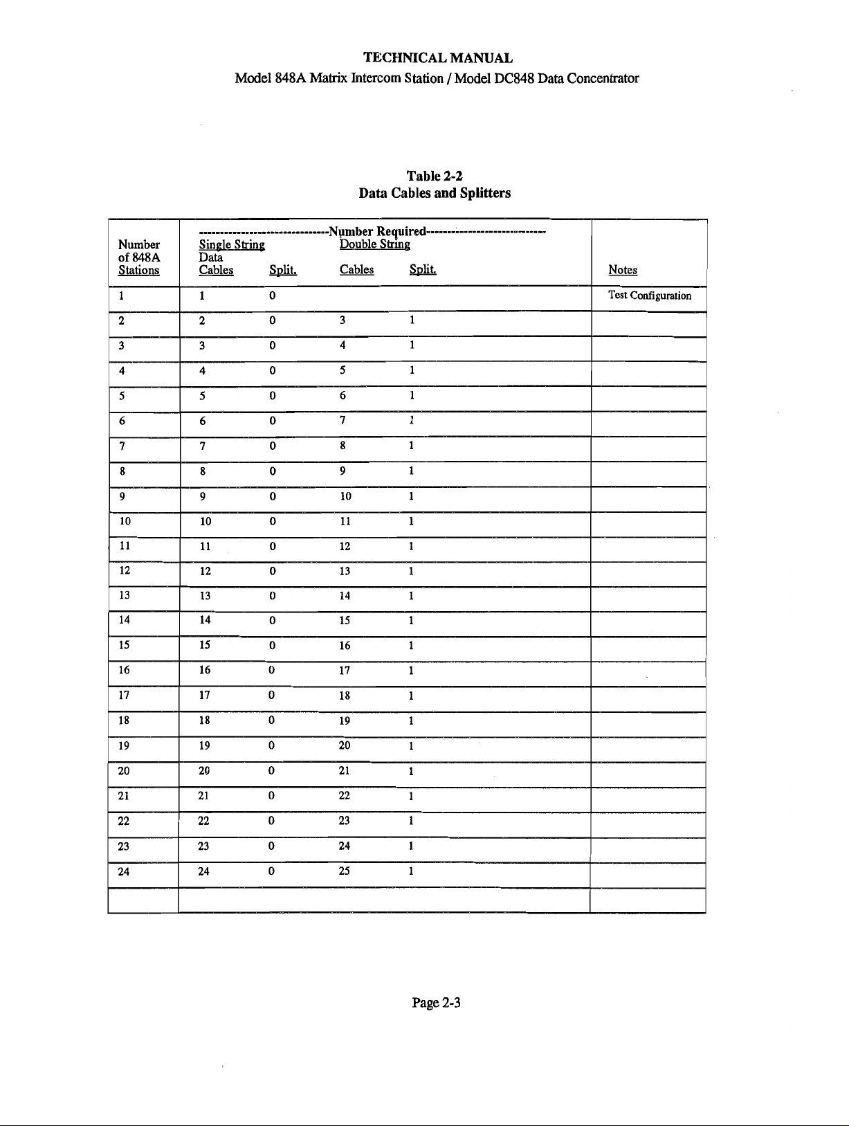
Table
2-1
DC848 Data
Concentrator
Matrix Audio Cables, Splitters, and Termination Plugs Required
Page
2-2
Page 23
Page 24

TECHNICAL MANUAL
Model 848A
Conference Audio Cables, Splitters, and Termination Plugs Required
Matrix
Intercom Station /Model DC848 Data Concentrator
Table
2-3
Page
2-4
Page 25
TECHNICAL MANUAL
Model
848A
Matrix
Intercom Station 1 Model DC848 Data Concentrator
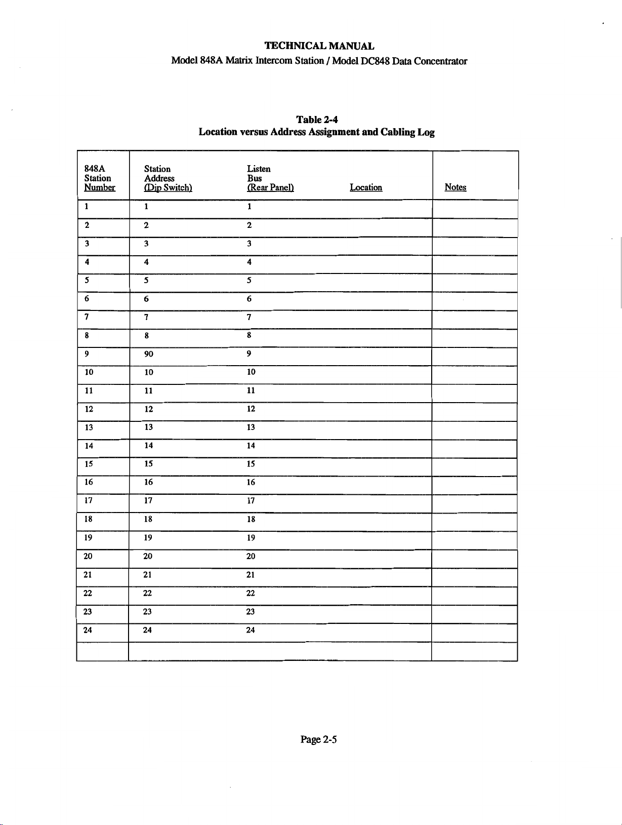
Table
2-4
Location versus Address Assignment and Cabling Log
Page
2-5
Page 26
Model 848A
TECHNICAL MANUAL
Matrix
Intercom Station / Model DC848
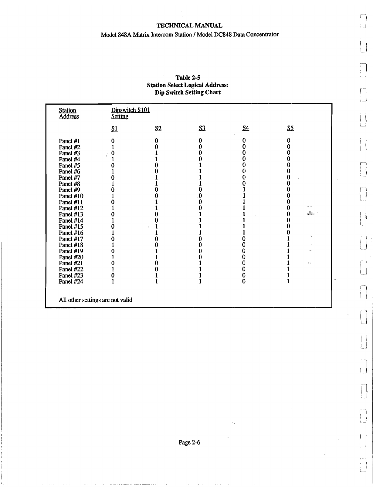
Table
2-5
Station Select
Dip
Logical
Switch Setting Chart
Address:
Data
Concentrator
Page
2-6
Page 27
TECHNICAL MANUAL
Model 848A
2.2
MECHANICAL INSTALLATION
The Mode1 848A mounts in an EIA standard 19-inch
equipment
Allow room for the panel microphone and controls in
front and the cabling in the rear. There are no
ventilation requirements.
The Model DC848 Data Concentrator mounts in an EIA
standard 19 inch equipment rack, and,
high. Allow room for cabling in the rear. There are no
ventilation requirements.
2.3
2.3.1
Power
transformer. The 14 volt
connects to a a four pin circular connector (plug). This
connector plugs in to a mating four pin circular power
input connector (receptacle)
rear panel. Tighten the retaining ring on the four pin
circular plug.
A
single 2 ampere slow-blow fuse, F701, is located on
the 848A rear panel. Replace only with a 2 ampere
slow-blow fuse. Metric fuses can
carrier
2802-0006-00 (Schurter
rack/enclosure, and is two rack units high.
ELECTRICAL
Power
is
supplied to the Model 848A via a step down
ac
is
changed
to
an
RTS Systems part number:
FEK
Matrix
Intercom Station /Model DC848 Data Concentrator
is
one rack unit
output of the transformer
,
J702, on the Model 848A
be
used when the fuse
031.1663).
and 51002, and the two connectors on the rear of the
DC848, J102 and 5103.Interconnect the data
connectors of the Model 848A's using RS422 9-pin
data cables. Connect one of the Model 848A
stations on the end to the Model DC848. The data
connectors on the back of the Model 848A are
labeled JlOOl and J1002, and wired in parallel. The
data connectors on the back of the Model DC848
labeled 5102 and 5103, and also wired in parallel.
(See System Block Diagmm on page ix).
In
some installations it will
to complete the string of digital cables.
System Diyital Connections. DC848 to Terminal or
Personal Com~uter
Use a standard RS232 cable to connect the DC848 to a
terminal. Use a null modem RS232 cable to connect the
DC848
plugging into the DC848A is a 25 pin female DB25
connector. The mating connector on the DC848 is 5101,
a male DB25 connector. The type of connector on the
end of the cable plugging into the terminal or personal
computer is determined by the terminal or personal
computer. Qn the
follows:
Pin2.
Pin
Pin 7
Shell
to
a personal computer. The end of the cable
...........
3
............
............
...:........
be
necessary to use a splitter
DC848 end the connections are as
Ax
.Tx
.Gnd
.Shield
are
23.2
Signal
2.3.2.1
Svstem Audio Connection
The 25 pair audio cables from the 848A
interconnected in parallel to form 25 balanced audio
buses. Connect the cables in parallel by using Model
4025A 1
5401 on each 848A to a splitter assembly. Splitter
assemblies are interconnected with
the male on one splitter to
(See Figure 1-1, System Block Diagram on page ix).
termination plug is sometimes required
(explained below).
Svstem Digital Connections. 848A to 848A to DC848
System digital connections are required when a The Model 848A
Model DC848 is used in the system. The system back panel, which sets the listen bus.
digital connections are paralleled RS422 cables.
These cables may connected by looping through on
the two connectors on the rear of the 848A, 51001,
System Audio and Digital Connections Conference Line
X
5 Splitter Assemblies. A cable is run from
25
pair
a
female on another splitter.
cables from
in
the system
See Section 2.4 for further details
(TW)
Connection
TW
The
Model 848A provides two conference-line channels. To
are
connect, simply insert a 3-pin XLR type male connector
from the
back panel of the Model 848A. However, this input
will not power
Intercom System Manual for details on how to install
and use a
A
23.2.2
23.2.2.1
Back Panel Jum~ers
On the Model 848A, it is not necessary to use the back
panel programming section to inhibit
Page 2-7
connector on the back panel of the
TW
Intercom line into the 5602 input on the
a
TW
Intercom system. Consult the
TW
Intercom System.
Listen Bus & Logical Address Selection
Listen Bus Selection (Audio)
has
a Listen Bus Selection area on the
a
station from
TW
Page 28
Model 848A
TECHNICAL MANUAL
Matrix
Intercom Station /Model DC848 Data Concentrator
calling other stations as was necessary on the Model
MS.
The Model 848A must be assigned its own station listen
bus by using jumpers. One of these jumpers connects a
pin in row C to the corresponding pin in row D; the
other jumper connects a pin in row E to the
corresponding pin in row
24
one of the
electronics of that unit.
The pushbutton on the front panel corresponding to the
listen address must now be designated
accented with a colored filter. This key represents its
own station
The position of this key must correspond to the listen
address selected by the jumpers on the rear panel.
23.2.23
Dir, Switch Setting
Step 1: After setting the Station Listen bus on the
panel, open the cover to access the internal dip switch.
Step 2: Using the dip switch settings given in Table 25,
set DIP SWITCH
on the rear panel and designated as a "call answer"
pushbutton on the front panel (see above).
23.2.3
Logical Address Selection (Digital)
System Termination Plugs
balanced listen buses to the listen
call
and can
SlOl to correspond to the address set
F.
Pins CD and
be
used for auto call answering.
EF
connect
"call answer" and
rear
terminate J602 on the back panel, with termination plug
RTS
P/N
9020-5 188-00.
23.2.4
Auxiliary Connections
The auxiliary connections on the back panel of the
Model 848A provide the user with a program input, an
unswitched microphone preamplifier output and access
to front panel connections. The program input accepts a
-10dBu signal which is distributed to both the
loudspeaker and the headsets. The level can
on the adjustment card.
The unswitched microphone preamplifier output
provides a -10
848A microphone.
Using a standard Molex
(supplied in your package), auxiliary connections
provide additional connections for the panel
microphone and the various headsets. A remote
microphone switch, such
set up in this way.
Pin
m
Installing Additional Features
dBu line level signal from the Model
KK,
0.156 center connector
as
a footswitch, can be also be
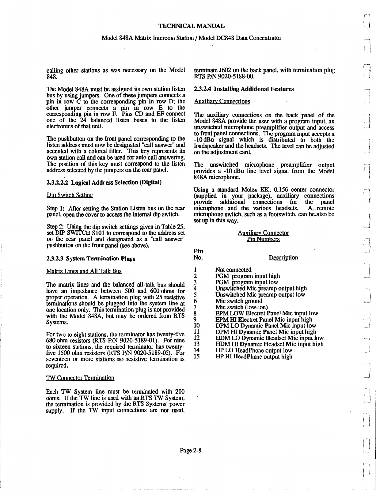
Auxiliaw Connector
Pin Numbe~
Description
be
adjusted
Matrix Lines and All Talk Bus
The matrix lines and the balanced all-talk bus should
have an impedance between 500 and 600 ohms for
A
proper operation.
terminations should be plugged into the system line at
one location only. This termination plug is not provided
with the Model
Systems.
For two to eight stations, the terminator has twenty-five
680 ohm resistors (RTS P/N 9020-5189-01). For nine
to sixteen stations, the required terminator has twenty-
five 1500 ohm resistors (RTS P/N 9020-5189-02). For
seventeen or more stations no resistive termination is
required.
TW
Connector Termination
Each
TW
System line must be terminated with 200
ohms. If the
the termination is provided by the RTS Systems' power
supply. If the
TW
termination plug with 25 resistive
848A, but may be ordered from RTS
line is used with an RTS
TW
input connections are not used,
TW
System,
Not connected
PGM program input high
PGM program input low
Unswitched Mic preamp output high
Unswitched Mic preamp output low
Mic switch ground
Mic switch (low=on)
EPM LOW Electret Panel Mic input low
EPM
HI
DPM LO Dynamic Panel Mic input low
DPM
HDM LO Dynamic Headset Mic input low
HDM
HP
HP
Electret Panel Mic input high
HI
Dynamic Panel Mic input high
HI
Dynamic Headset Mic input high
LO Headphone output low
HI
Headphone output high
Page 2-8
Page 29
TECHNICAL
MANUAL
Model 848A
Remote Micro~hone Switching
There are two ways
Through the rear panel Mic switch, or via a phantom
connection through the dynamic headset connector.
Rear Panel Microphone Switch:
A
remote footswitch or other
connected to the auxiliary connector through pins 6 and
7.
When the switch is closed the microphone signal is
turned on and the front panel tally (in the Mic ON
pushbutton) will illuminate
Note that the front panel pushbutton may override the
remote switch and
to
switch a remote microphone:
lock
on the microphone switches.
Matrix
Intercom Station / Model DC848 Data Concentrator
dry
contact may
to
its bright (active) state.
be
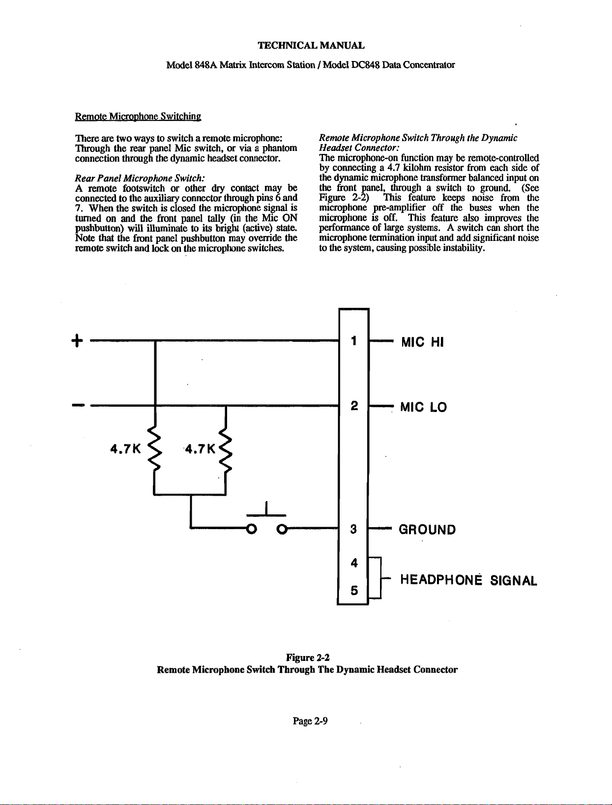
Remote Microphone Switch Through the Dynamic
Headset Connector:
The microphone-on function may be remote-controlled
by connecting a 4.7 kilohm resistor from each side of
the dynamic microphone transformer balanced input on
to
fiont panel, through a switch
the
Figure 2-2) This feature keeps noise from the
microphone pre-amplifier off the buses when the
microphone is off. This feature also improves the
performance of large systems.
microphone termination input and add significant noise
to the system, causing possible instability.
A
ground.
switch can short the
(See
MIC HI
MIC
LO
GROUND
HEADPHONE
figure
Remote Microphone Switch Through The Dynamic Headset Connector
2-2
SIGNAL
Page 2-9
Page 30
TECHNICAL MANUAL
Model 848A Matrix Intercom Station /Model DC848 Data Concentrator
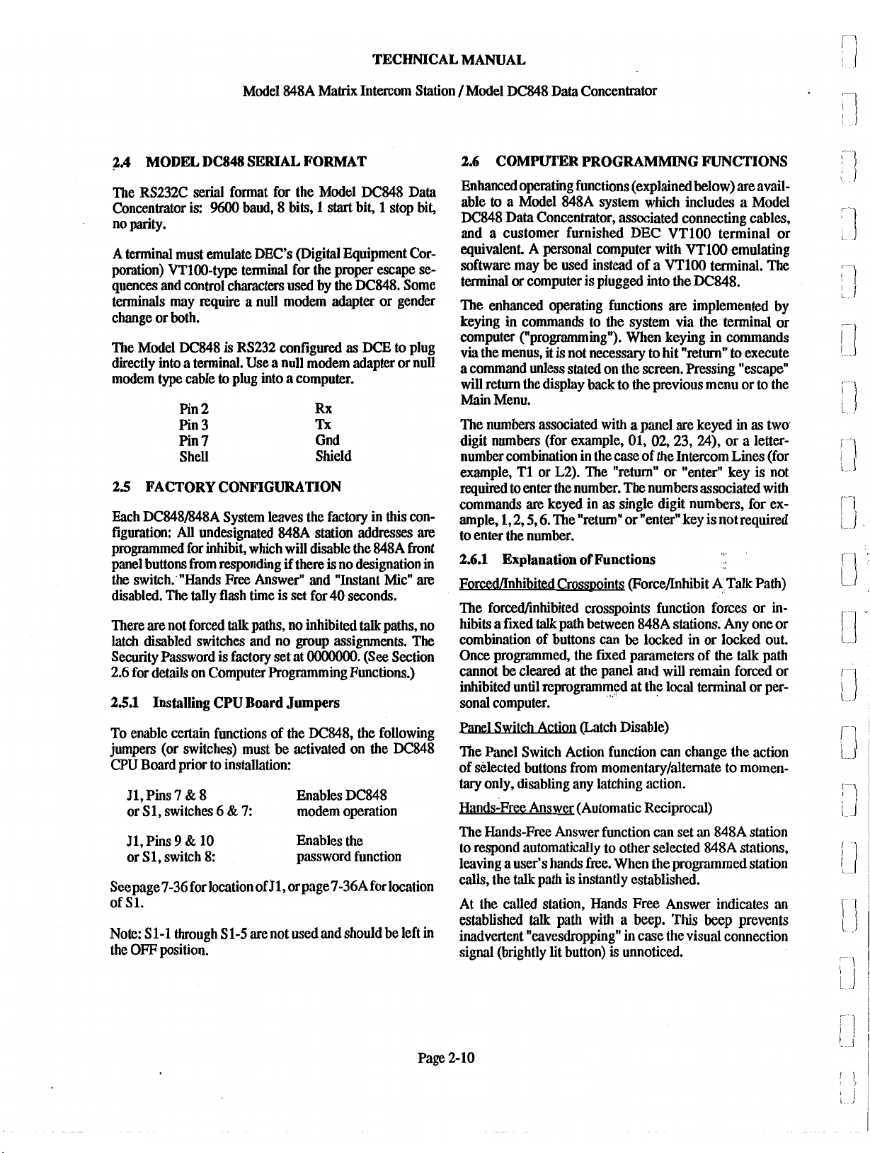
2.4
MODEL DC848 SERIAL FORMAT
The RS232C serial format for the Model DC848 Data
%00
Concentrator is:
no parity.
A terminal must emulate DEC's (Digital Equipment Cor-
poration) VT100-type terminal for the proper escape se-
quences and control characters
terminals may require a null modem adapter or gender
change or both.
The Model DC848
directly into a terminal. Use a null modem adapter or null
modem type cable to plug into a computer.
Pin 2 Rx
Pin 3 Tx
Pin 7 Gnd
Shell Shield
2.5
FACTORY CONFIGURATION
Each DC848/848A System leaves the factory in this con-
figuration:
programmed for inhibit, which will disable the 848A front
panel buttons from responding
the switch.'"Hands Free Answer" and "Instant Mic"
disabled. The tally flash time is set for 40 seconds.
There are not forced
latch disabled switches and no group assignments. The
Security Password is factory set at
2.6 for details on Computer Programming Functions.)
2.5.1
AU
Installing CPU Board
baud, 8 bits, 1 start bit, 1 stop bit,
used
by the DC848. Some
is
RS232 configured as
undesignated 84844 station addresses
if
there is no designation in
talk
paths, no inhibited
OOOOOOO.
DCE
to plug
talk
paths, no
(See Section
Jumpers
m
m
2.6
COMPUTER PROGRAMMING FUNCTIONS
Enhanced operating functions (explainedbelow) are avail-
to
able
DC848 Data Concentrator, associated connecting cables,
and a customer furnished DEC VTlOO terminal or
equivalent. A personal computer with VTlOO emulating
software may be used instead of a VTlOO terminal. The
terminal or computer is plugged into the DC848.
The enhanced operating functions
keying in commands to the system via the terminal or
computer ("programming"). When keying in commands
via
a command unless stated on the screen. Pressing "escape"
will return the display back to the previous menu or to the
Main
The numbers associated with a panel are keyed in as two
digit numbers (for example, 01, 02,23,
number combination in the case of the Intercom Lines (for
example, T1 or L2). The "return" or "enter" key is not
required to enter the number. The numbers associated with
commands
ample, 1,2,5,6. The "return" or "enter" key is not required
to enter the number.
2.6.1
ForcedDnhibited Crosspoints (ForceIInhibit A Talk Path)
The forced/inhibited crosspoints function forces or in-
hibits a fixed
combination of buttons can
Once programmed, the fixed parameters of the
cannot
inhibited until reprogrammed at the local terminal or per-
sonal computer.
a Model 848A system which includes a Model
are
implemented by
the menus, it is not necessary to hit "return" to execute
Menu.
24),
or a letter-
are
keyed in as single digit numbers, for ex-
Explanation of Functions
talk
path between 84814 stations. Any one or
be
locked in or locked out.
talk
path
be
cleared at the panel and will remain forced or
To enable certain functions of the DC848, the following
jumpers (or switches) must be activated on the
CPU Board prior to installation:
J1,Pins 7
or S1, switches 6
J1, Pins
or S1, switch 8:
Seepage7-36 for location of J1, orpage7-36Afor location
of S1.
Note: S 1-1 through S 1-5 are not used and should be left
the OFF position.
9
&
&
8
10
&
7:
Enables DC848
modem operation
Enables the
password function
Page
Rafch
The Panel Switch Action function can change the action
of selected buttons from momentarvlalternate to momen-
tary
only, disabling any latching action.
~ands-~ree Answer (Automatic Reciprocal)
The Hands-Free Answer function can set
to respond automatically to other selected 848A stiltions,
leaving a user's hands free. When the programmed station
calls, the
At the called station, Hands Free Answer indicates an
established
in
inadvertent "eavesdropping" in case the visual connection
signal (brightly lit button) is unnoticed.
2-
10
talk
path
talk
is
instantly established.
path
with a beep.
an
This
beep prevents
ill
848A station
Page 31

TECHNICAL
MANUAL
Model 848A
Matrix
Intercom Station 1 Model DC848 Data Concentrator
"Instant Mic On"
When set, the microphone will turn on automatically
a
whenever
call is originated.
"Instant S~eaker On"
him
When set, the loudspeaker will automatically
whenever a call
is
received.
on
Tallv Flash Time
When a call is received at an 848A station, the
pushbutton corresponding to the calling station will
talk
path
is
flash (if the
not already on), providing a
tally that tells the responding operator where the
incoming call originated.
If
the
talk
path is already on,
then the communication is already established and tally
is not required. The length of time the pushbutton will
to
flash is variable from a 10-second minimum
a 60-
second maximum and can be set from the Tally Flash
Time Menu. Press
L
or S to lengthen or shorten the
tally time.
Panel Group Assignment
Using the Panel Group Assignment List, 848A units
within the matrix can be programmed into preset
groups. Each group would then act as a single unit in
receiving communications from the panel being
programmed. Up to four groups can be created, and
as
many units as needed can be assigned to each group.
SYSTEM STATUS
Dvnamic Comlink Dis~lavs
This display indicates all 848A panels that are currently
communicating with the Model DC848 on the RS485
serial line. This status display is dynamic, meaning that
it will reflect a change in status
as
it happens, without
reset. There are two ways to get to this display: 1) By
choosing
or
#1 on the Dynamic System Status root menu,
2)
By hitting [return] whenever any menu displays
the message, "THIS panel not communicating with the
system".
Dvnamic Matrix Status Dis~lay
SYSTEM COmGURATION
This series bf displays allows a user to save into
memory all programmed parameters (i.e latch disable,
groups, forced crosspoints and all other settings
throughout the entire
system) so that the data is not lost.
~ara~eters may be sa;ed and recalled for two full
configurations.
There
is
also
a
reset
Password Security Menu
The Password Security Menu is designed to prevent
casual or inadvertent tampering with system settings,
and to prevent unauthorized use of the modem
connection. After entering the password into the system
by following the sequence, it is recommended that
whenever you exit the program you do so into the
Security Mode. As an additional security measure,
unplug and remove the terminal from the
,
programming is completed. When accessing the system
DC848 when
by modem, an exit into the Security Mode automatically
disconnects the modem.
There is a
safeguard built into the system in the event
that the password programmed into the system is
misplaced, unknown or forgotten. First remove the
DC848 cover, then remove the jumper from
J1
10 or turn off switches 6 & 7 of S1 (see page 7-36 or
7-36a for the location). This will enable you to access
the system without a password. Next, choose the
Password Security menu and create a new password.
9
&
Finally, replace the jumper on
&
7
switches 6
of S1.
This will activate the new
J1 pins
10 or turn on
password.
2.6.2
Programming the
848AIDC848
Enhanced
Functions
The Main Menu
The 848A enhanced functions are programmed via
computer screen menus from the
DC848. The first
menu, The 848A Main Menu (See Figure 3-3), lists a
submenu for'each enhanced function. Enter a single
digit to display an enhanced function submenu.
Pins
9
&
This display indicates all possible
talk
paths in the
system and their current status (i.e. communicating, not
communicating). This display can be reached though
the Dynamic System Status root menu. A Panel number
appears in the appropriate crosspoint to indicate that the
"--"
crosspoint button has been illuminated.
indicates
that the crosspoint button is off.
Page
2-
11
Page 32

TECHNICAL
MANUAL
Model 848A
IMPORTANT NOTE:
If there is a beep and the following message appears:
"THIS PANEL NOT
WITH THE SYSTEM",
entering the 2-digit panel number or go to the
System Status Display to recheck panel status.
The Forcellnhibit A Talk Path List (Forced Crosspointk
On the FORCE/INHIBIT A TALK PATH LIST (See
Figure 3-4A) the panel number being displayed or pro-
grammed is at the top of the screen. The chart lists the
talk
path switches in this panel that access the other
panels in the system, and shows the status of each
("ON indicates a forced
talk
forced
always ON state independent of the corresponding
button, choose
OFF state, choose "2". Once you have chosen the
function, you must choose the other panel number in the
path to be forcedfinhibited.
path). To force a
"1."
talk
To inhibit a talk path
Matrix
Intercom Station / Model DC848 Data Concentrator
COMMUNICATING
select another panel by
path,
"--"
talk
indicates a non-
path (crosspoint) to an
to
an always
The Hands-Free Answer List (Auto Reciprocal):
The HANDS-ME
stations the 848A operator can automatically respond to
when that station calls. The panel number being
displayed or programmed
selected panel number will show as
3-7A) To program this feature, choose "1"; to de-
program this feature, choose "2". Then enter the two-
digit panel number to be changed. (See Figure 3-7B)
The Panel Instant Mic Assignment List
The PANEL INSTANT MIC ASSIGNMENT LIST
enables a user to
particular panel. (See Figure 3-8) To use this feature,
first display the number of the panel you want to
program. To program this feature choose
program this feature, choose
digit panel number to be changed. A panel which has
Instant Mic will appear on the display
ANSWER
is
turn
on the Instant Mic function for a
LIST shows which
at the top of the screen. A
"HF.
"2".
Then enter the two-
as
"IM.
(See Figure
"1";
to de-
;
From that point, there is a toggle ON/OFF action for
that function. If the function is on and ENTER is
pressed, it will toggle off;
ENTER
on the display
show
Note:
interactive; the last function programmed takes
precedence.
The Panel Switch Action Menu (Latch Disable):
On the PANEL SWITCH ACTION
3-6A), the panel number of the 848A being displayd or
programmed is at the top of the screen. Each of the 24
pushbuttons or station-select-switches on the front panel
is normally both alternate-action and momentary-action.
If held, the pushbutton's action will be momentary,
releasing the talk-path when the pushbutton is released.
If pressed with a light tap
talk-path will be latched on until the pushbutton
depressed again to turn off the talk path. It is possible
to make any of these buttons momentary action only.
The chart shows the status of each button or station
switch for a particular panel. A latch disabled button is
shown
momentary action only, type "1". To restore a button to
both actions, type
pushbutton number to be changed (See Figure 3-6B).
will toggle it on. A forced
as
"FO" and an inhibited
as
"IH.
THE
FORCEIINHIBIT
as
"LD". (See Figure 3-6A) To make the button
if
the function is off, pressing
talk
path with show
A TALK PATH WST
MENU
(i.e., less than
"2".
Then enter the two-digit
talk
path will
(See Figure
1
second), the
is
is
The Panel Instant Speaker Assignment List
The PANEL INSTANT SPEAKER ASSIGNMENT
LIST enables a user to turn on the Instant Speaker
function for a particular panel. To use this feature, first
display the number of the panel you want to program.
to
"IS".
de-program
"1";
"2".
At the
01
or L2)
to
Next, to program this feature choose "1;
this feature choose
number to be changed. A panel which has Instant
Speaker will appear on the display
The PANEL GROUP ASSIGNMENT LIST assigns
switches into groups, and the assignments apply only to
communications from the panel being set. First, display
the panel number of the panel you want to program.
Then, to assign a switch to a group, choose
remove a switch from a group, choose
prompts, enter the one-digit group number (i.e, 1-4),
then the two-digit switch number (ie.,
involved in the programming.
"2".
Then enter the two-digit panel
as
Page 2-12
Page 33

TECHNICAL MANUAL
Model 848A
panel Tallv Setw
The
PANEL
tally flash time. To shorten the time, choose "1"; to
lengthen the time, choose
reflect a longer or shorter time until your adjustment
completed.
Bvnamic Comlink Sw Displav and Dvnamic Matrix
Btus Dimlay
Neither of these status display panels can be
programmed in any way other than altering the status of
a unit. Both these displays are dynamic; that is, they
update without reset to reflect any change in status.
Svstem Configuration Menus
From the System Configuration Root Menu,
configurations can be stored or retrieved, or the entire
system can be reset to allow a completely new
configuration. Using the Store Configuration sub-
menu, two configurations (A and B) can be stored, and
the screen supplies a warning message when
be overwritten. From the Retrieve Configuration sub-
menu, the two stored configurations can be accessed,
and a warning message appears on the screen whenever
the current system setup is overwritten.
Reset Svstem Root Menu
To reset to System Setup only, press
system setup and the setups of all individual panels,
press
"2".
To alter the security code password, press "3".
TALLY
This intermpts all current communications.
SERW shortens or lengthens the
"2".
Matrix
The display will then
Intercom Station 1 Model DC848 Data Concentrator
is
data
will
"1".
To reset the
Make sure that power to the modem is on before the
Model DC848 is powered up. If
interrupt power to the DC848 and restart.
A Basic Time Model BT2400E modem has been tested
with the DC848 system. The DC848 works best with
modems with a command set similar to the Model
this
is not the case,
BrnOOE.
2.8.2
Modem
To sign on, set 2400,1200,600 or 300 baud, 8
stop bit, one start bit, no parity. Set the terminal for
VTlOO emulate. When using a communications
package, insert the phone number.
This program is intended to run at 2400 baud because
the time required to refresh the screen through the
modem is 118 the rate of direct (no modem)
communication at 9600 baud. The other baud rates
should
be
phone line is noisy. Whenever possible, use 2400 baud.
The Model
one ring. There
the screen appears, calling up either the password menu
or the main menu, depending upon security.
DC848 initializes the modem every two minutes to
The
overcome power transients that may reset the modem
and not the DC848.
Operation
bits,
used only
DC848 modem mode is set to answer within
if
2400 baud won't work, or if the
is
normally a two-second delay before
one
2.7
DOWNLOADING SYSTEM SETTINGS
An
entire 848A system may be set up from a computer
which is equipped with
Appendix B for a complete explanation.
2.8
MODEM OPERATION
2.8.1
Modem Installation
certain
~~k~
for modem opemtion. (See Section 2.5.1 and Figure 2-
1).
To connect, use a null modem cable between the DC848
and
the modem. The cable connects at pins 2,3 and
that the
a
floppy disc capability.
CPU
board is correctly jumpred
see
7.
Page 2-13
X,
When exiting the program, use
automatically disconnect the modem.
After three-and-a-half minutes of no activity, the
modem will also automatically disconnect. In case of
wwer failure. there will be a 5 second delav in
iestoration of the program.
2.9
RESETTING AN INDIVIDUAL 848A PANEL
An
individual panel may have
by holding in button #l(u~~er-left hand button) while
power is shut off and then reapplied to that panel.
the Security Mode, to
its
micro-processor reset
a
Page 34

TECHNICAL MANUAL
Model 848A
Matrix
Intercom Station 1 Model DC848 Data Concentrator
RTS SYSTEMS INC. 848A SYSTEM TERMINAL CONTROL PROGRAM VERSION
848A MAIN MENU
1.
FORCEANHIBIT A TALK PATH
5.
INSTANT SPEAKER ASSIGNMENTS
6.
GROUP LIST ASSIGNMENTS
7.
TALLY FLASH TIME
8. SYSTEM STATUS DISPLAYS
9.
SYSTEM CONFIGURATION
X. EXIT TO SECURITY MENU (DISCONNECTS MODEM)
ENTER SELECTION:
Figure
Main
Menu
2-3
Display
6.0
Page
2-
14
Page 35

Model
848A
Matrix
TECHNICAL MANUAL
Intercom Station 1 Model
DC848
Data
Concentrator
PANEL NUMBER
04 02 03 04 05
13 14 15 16 17 18
T1
L1
1.
TOGGLE FORCED TALK PATH
2.
TOGGLE INHIBIT TALK PATH
3.
DISPLAY ANOTHER PANEL
4.
DISPLAY NEXT PANEL
5.
RETURN TO MAlN MENU
ENTER SELECTION:
0-
T2
01
FO
L2
--
06
Forceanhibit A Talk Path:
PANEL NUMBER
13 14 15 16 17 18
01
09 08
19
Figure
Selecting
19
09
10 11 12
20 21 22 23 24
2-4A
a
Function
20 21 22
23
24
TI
2.
3.
4.
5.
ENTER TALK PATH TO CHANGE FORCE STATE
L1
T2
L2
1.
TOGGLE FORCED TALK PATH
TOGGLE INHIBIT TALK PATH
DISPLAY ANOTHER PANEL
DISPLAY NEXT PANEL
RETURN TO MAlN MENU
Figure
Forceanhibit A Talk Path:
Selecting
(01-L2):
A
Page
2-4B
Talk Path
2-
15
Page 36

TECHNICAL MANUAL
Model
M8A
Matrix
Intercom Station /Model DC848
RTS SYSTEMS INC. 848A PANEL SWITCH ACTION MENU (LATCH DISABLE)
PANEL NUMBER 01
01 02 03
..
--
--
04
--
05
--
06
07 08 09 10 11 12
LD
--
--
--
Data
--
Concentrator
--
--
13 14 15 16 17 18 19 20 21 22 23 24
--
--
TI L1 T2
--
-- --
I.
SET LATCH DISABLE MOMENTARY ONLY)
2. CANCEL LATCH DISA LE MOMENTARY ONLY)
3. DISPLAY ANOTHER PANEL
4. DISPLAY NEXT PANEL
5. RETURN TO MAlN MENU
ENTER SELECTION:
PANEL NUMBER 01
01 02 03
13 14 15 16 17 18 19 20 21 22 23 24
TI Ll T2
1. SET LATCH DISABLE (MOMENTARY ACTION
2.
CANCEL LATCH DISABLE (MOMENTARY Ac+IoN)
3. DISPLAY ANOTHER PANEL
4. DISPLAY NEXT PANEL
5. RETURN TO MAlN MENU
SET LATCH DISABLE (MOMENTARY ONLY) FOR SWITCH NUMBER (01-L2):
--
--
--
--
--
--
--
L2
--
B
Figure 2-5A
Panel Switch Action Menu (Latch Disable):
Selecting a Function
04
05
06
--
L2
07 08 09 10 11 12
LD
--
--
--
--
Figure 2-5B
Panel Switch Action Menu:
Selecting a Switch Button
Page
2-16
Page 37

Model
848A
Matrix
TECHNICAL MANUAL
Intercom Station /Model
DC848
Data Concentrator
RTS SYSTEMS INC.
PANEL NUMBER
13 14 15 16 17 18
1.
SET HANDS-FREE ANSWER
2.
CANCEL HANDS-FREE ANSWER
3.
DISPLAY ANOTHER PANEL
4.
DISPLAY NEXT PANEL
5.
RETURN TO MAlN MENU
ENTER SELECTION:
01
848A
HANDS-FREE ANSWER LIST (AUTO RECIPROCAL)
Hands-Free Answer (Auto-Reciprocal) Function Menu:
PANEL NUMBER
01 02 03 04 05
01
06
-0
19
20 21 22 23 24
Figure 2-6A
Selecting a Function
07
08
HF
09
0-
10 11 12
13 14 15 16 17 18 19 20 21 22 23 24
SET HANDS-FREE ANSWER
1.
2.
CANCEL HANDS-FREE ANSWER
3.
DISPLAY ANOTHER PANEL
4.
DISPLAY NEXT PANEL
5.
RETURN TO MAlN MENU
SET HANDS-FREE ANSWER FOR SWITCH NUMBER
(01-24):
Figure 2-6B
Set Hands-Free Answer (Auto-Reciprocal)
Menu:
Selecting a Panel Number
2-17
Page
Page 38

TECHNICAL MANUAL
Model
848A
Matrix
RTS SYSTEMS INC. 848A INSTANT MIC ASSIGNMENT LIST
PANEL NUMBER 01
1. SET INSTANT MIC ON FOR A SWITCH
2. CANCEL INSTANT MIC ON FOR A SWITCH
3.
DISPLAY ANOTHER PANEL
4. DISPLAY NEXT PANEL
5.
RETURN TO MAlN MENU
Intercom Station
/
Model
DC848
Data
Concentrator
ENTER SELECTION:
Figure 2-7A
Instant Mic On: Choosing
RTS SYSTEMS INC. 848A INSTANT MIC ASSIGNMENT LIST
PANEL NUMBER 01
1. SET INSTANT MIC ON FOR A SWITCH
2. CANCEL INSTANT MIC ON FOR A SWITCH
3.
DISPLAY ANOTHER PANEL
4. DISPLAY NEXT PANEL
5.
RETURN TO MAlN MENU
SET INSTANT MIC FOR SWITCH NUMBER (01-L2):
Figure
2-7B
Instant Mic On: Selecting a Switch
a
Function
I
w
I
Page
2-18
Page 39

Model
PANEL NUMBER 01
848A
TECHNICAL MANUAL
Malfix
Intercom Station / Model
DC848
Data
Concentrator
01 02 03
13
14
TI L1 T2
1. SET INSTANT SPEAKER ON FOR A SWITCH
2. CANCEL INSTANT SPEAKER ON FOR A SWITCH
3. DISPLAY ANOTHER PANEL
4. DISPLAY NEXT PANEL
5.
RETURN TO MAlN MENU
ENTER SELECTION:
01 02
13 14
04
05
06
07 08
--
1s
--
15
16
19
18 19
42
03
04
05
06
07 08 09 10 11 12
--
1s
--
15
16 17 18 19 20 21 22 23 24
09
10
20
21 22 23 24
11 12
T1 L1 T2
1.
SET INSTANT SPEAKER ON FOR A SWITCH
2. CANCEL INSTANT SPEAKER ON FOR A SWITCH
3. DISPLAY ANOTHER PANEL
4. DISPLAY NEXT PANEL
5.
RETURN TO MAlN MENU
SET INSTANT SPEAKER ON FOR SWITCH NUMBER
L2
Figure
Instant Speaker On: Selecting a Switch
Page
(01
42):
2-8B
2-19
Page 40

TECHNICAL MANUAL
Model
848A
Matrix
RTS SYSTEMS INC. 848A PANEL GROUP ASSIGNMENT LlST
PANEL NUMBER 01
1. ASSIGN SWITCH TO A GROUP
2.
REMOVE SWITCH FROM GROUP ASSIGNMENT
3.
DISPLAY ANOTHER PANEL
4. DISPLAY NEXT PANEL
5.
RETURN TO MAlN MENU
Intercom Station / Model
DC848 Data Concentrator
ENTER SELECTION:
Figure 2-9A
Panel Group Assignment: Selecting
RTS SYSTEMS INC. 848A PANEL GROUP ASSIGNMENT LlST
PANEL NUMBER 01
I.
ASSIGN SWITCH TO A GROUP
2.
REMOVE SWITCH FROM GROUP ASSIGNMENT
3.
DISPLAY ANOTHER PANEL
4. DISPLAY NEXT PANEL
5.
RETURN TO MAlN MENU
ASSIGN SWITCH TO GROUP, ENTER GROUP NUMBER (1-4): 1
ENTER SWITCH NUMBER (01-L2):
Figure 2-9B
Panel Group Assignment: Assigning A Group
a
Function
I
I
Page
2-20
Page 41

TECHNICAL
Model
848A
Matrix
Intercom Station /Model DC848 Data Concentrator
RTS SYSTEMS INC. 848A PANEL TALLY SETUP
PANEL NUMBER 01
MANUAL
AUTO TALLY FLASH TIME
1.
LENGTHEN TALLY FLASH TlME (MAX 60 SECONDS)
2.
SHORTEN TALLY FLASH TlME (MIN
3.
DISPLAY ANOTHER PANEL
4.
DISPLAY NEXT PANEL
5.
RETURN TO MAlN MENU
[
L 1 Tally Flash Time Longer (Max. 60
[ S ]
Tally Flash Time Shorter (Min.
......................
Sec.)
10
Sec.)
10 SECONDS
10
SECONDS)
Figure
2-10
Panel Tally Setup
RTS SYSTEMS INC. 848A SYSTEM TERMINAL CONTROL PROGRAM
848A DYNAMIC DISPLAY ROOT MENU
1.
DISPLAY DYNAMIC COMLINK STATUS
2.
DISPLAY DYNAMIC MATRIX STATUS
5.
RETURN TO MAlN MENU
ENTER SELECTION:
Dynamic Display Root Menu
Figure
Page
2-11
2-21
Page 42

Model
848A
Matrix
TECHNICAL
MANUAL
Intercom Station /Model
DC848
Data Concentrator
RTS SYSTEMS INC.
OK = Panel is communicating with system
--
E
Panel is not communicatln with system
XX
=
Commun~cahon collis~n
[Return] TO
RTS SYSTEMS INC.
P#
09: 01 02 03
MAIN
,,
,,
,, ,, ,,
--
,,
,,
,,
--
--
--
--
--
--
--
--
--
--
--
-- --
--
,,
--
-,
--
,,
-- --
-- --
--
om
--
..-
--
--
--
-,
.-
--
--
--
848A
MENU
868A
DYNAMIC MATRIX STATUS DISPLAY
**
,- ,,
**
,, ,, ,, ,,
-, ,,
,,
--
--
--
--
--
--
--
--
--
-..
,, ,,
,-
-,
04
,, ,,
--
--
--
,, -,
,,
--
--
**
,,
,,
05
-- --
--
,,
,-
,,
--
,-
-- -- --
--
--
,.
--
--
-*
--
--
..
--
--
-.
.-
-- --
DYNAMIC COMLINK STATUS DISPLAY
72
or more panels at same address)
,,
,,
**
-..
--
06
.,
--
.,
--
..,
.-
--
-..
..-
--
--
--
--
--
Dynamic
..,
,, ,, ,, ,,
--
--
,,
,,
,,
..,
,,
**
-, ,,
,-
**
,, -,
-- --
,,
--
--
,,
,,
,-
,,
-,
,,
--
,,
--
-,
-,
--
,,
08
--
-,
..,
,,
,,
--
-..
--
--
--
--
--
--
**
,,
--
,,
,,
,,
,,
,,
-,
,,
--
,,
--
--
--
--
Figure
Comlink
,, ,,
,,
,,
-,
--
**
10
--
-,
,,
,,
-,
--
--
--
,-
--
--
r-
--
2-12A
Status Display
,,
--
,,
,-
,,
,,
,,
,,
,,
,, ,,
,,
,,
,,
,,
,..
,,
--
--
--
,,
,,
--
**
--
--
,,
**
,,
,,
,,
**
,,
,,
--
,,
,,
--
,,
,,
--
,,
,,
-,
,,
,.
-,
--
,,
--
-,
,,
..,
-. -.
-,
--
--
--
,,
,,
,- -, ,, -,
-.
--
--
--
,,
,,
,, ,,
--
--
14
,,
,,
**
,,
,,
,, ,, ,,
,,
-,
,,
-,
,, -, ,,
--
--
--
--
--
--
,,
--
,,
,-
,, ,-
,,
--
-..
--
--
-- --
,-
,, ,,
,,
--
--
,,
**
,,
--
**
,-
,-
--
-,
-, ,,
--
,,
,,
-- --
-- --
--
--
,, ,,
,-
,,
,,
,, ,-
--
18
,-
--
--
--
,, -,
,,
--
--
-,
,-
,,
,-
--
**
,,
,-
**
,-
,,
,,
--
,-
,,
,,
,- -,
,,
,, ,-
--
--
I
-.
,,
-,
,,
,,
-,
-..
,,
--
-,
,,
,- ,,
,-
--
--
**
-,
,- -,
-*
--
--
--
,,
,..
--
,,
--
,,
,-
,- ,,
-- --
,,
,- -,
--
-..
,-
,,
--
,-
,, ,-
--
,,
-,
,,
,,
,, ,,
,,
..-
**
,,
**
--
,,
,,
,,
--
,-
--
,,
--
,,
,-
--
,,
--
,-
,, ,,
--
..-
-,
--
,-
--
--
--
-,
..-
,-
-,
--
,,
--
,,
--
,, ,, ,-
,-
,,
,, ,,
,-
,, ,-
,,
--
**
,- ,-
--
**
--
--
I
I
,-
,-
,-
,-
,-
,..
,,
,-
,-
--
,,
,.
,-
,-
,,
,,
,-
**
Rgure
2-12B
Dynamic Matrix Status Display
Page
2-22
Page 43

TECHNICAL MANUAL
Model
848A
Matrix
Intercom Station
RTS SYSTEMS INC. 848A SYSTEM TERMINAL CONTROL PROGRAM
848A SYSTEM CONFIGURATION ROOT MENU
1.
STORE CURRENT CONFIGURATION
2.
RETRIEVE A CONFIGURATION
3.
RESET AND INITIALIZATION
5.
RETURN TO MAlN MENU
ENTER SELECTION:
/
Model
D6848
Data
Concentrator
Figure
2-I3
System Configuration Root Menu
RTS SYSTEMS INC. 848A SYSTEM TERMINAL CONTROL PROGRAM
STORE CONFIGURATION SUB MENU
1.
STORE CURRENT SETUP TO CONFIGURATION A
2.
STORE CURRENT SETUP TO CONFIGURATION
5.
RETURN TO MAlN MENU
STORE CURRENT SETUP TO CONFIGURATION
***+******C***
SETUP PREVIOUSLY STORED TO CONFIGURATION
WARNING****************"
Figure
2-14A
Store Configuration Sub Menu and selection
f
B
[
A
]
[
A]
WILL
BE
OVERWRITTEN
Page
2-23
Page 44

TECHNICAL MANUAL
Model
848A
Matrix
Intercom Station / Model
RTS SYSTEMS INC. 848A SYSTEM TERMINAL CONTROL PROGRAM
RETRIEVE CONFIGURATION SUB MENU
1.
RETRIEVE SETUP FROM CONFIGURATION A
2.
RETRIEVE SETUP FROM CONFIGURATION
3.
4.
5.
RETURN TO MAIN MENU
DC848
Data
Concentrator
1
B
]
ENTER SELECTION:
RETRIEVE SETUP FROM CONFIGURATION [ A]
*************
CURRENT SYSTEM SETUP WILL BE OVERWRITTEN
DO YOU WISH TO CONTINUE?:
ANY OTHER RETURNS TO ROO MENU
WARNING***************
1
Figure
FOR YES]
'7
2-14B
Retrieve Configuration Sub Menu and selection
?{;.
,
,*.
.?.A'
Page
2-24
Page 45
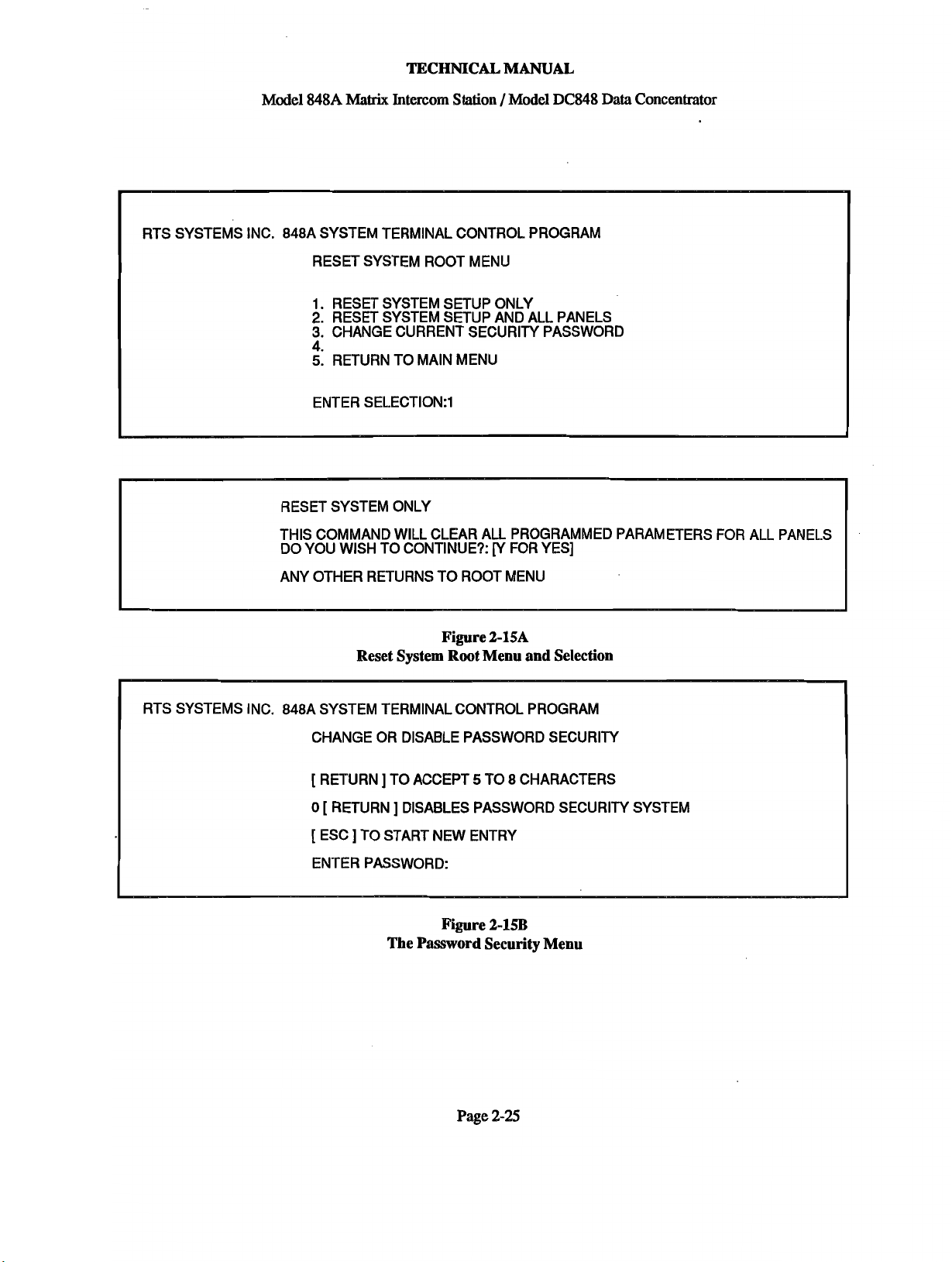
TECHNICAL. MANUAL
Matrix
Model 848A
RTS SYSTEMS INC. 848A SYSTEM TERMINAL CONTROL PROGRAM
RESET SYSTEM ROOT MENU
1. RESET SYSTEM SETUP ONLY
2.
RESET SYSTEM SETUP AND ALL PANELS
3.
CHANGE CURRENT SECURITY PASSWORD
5.
RETURN TO MAIN MENU
ENTER SELECTI0N:l
RESET SYSTEM ONLY
Intercom Station /Model DC848 Data Concentrator
THIS COMMAND WILL CLEAR AU PROGRAMMED PARAMETERS
DO YOU WISH TO CONTINUE?:
ANY OTHER RETURNS TO ROOT MENU
Rgure
[Y
FOR YES]
2-15A
Reset System Root Menu and Selection
RTS SYSTEMS INC. 848A SYSTEM TERMINAL CONTROL PROGRAM
CHANGE OR DISABLE PASSWORD SECURITY
[
RETURN ] TO ACCEPT 5 TO 8 CHARACTERS
0
[
RETURN ] DISABLES PASSWORD SECURITY SYSTEM
[
ESC ] TO START NEW ENTRY
ENTER PASSWORD:
Figure
2-193
The Password Security Menu
FOR
ALL PANELS
Page
2-25
Page 46

Model
848
A
mix
TECHNICAL MANUAL
Intercom Station /Model
DC848
Data Concentrator
Figure
Model 848A Front Panel
3-1
Page 2-26
Page 47

Model
TECHNICAL
$488
Matrix Intercom Station / Model
MANUAL
DCS48
Data Concentrator
SECTION
3.1
Operating Controls
Table
S:
OPERATION
3-1
below lists the Model
(See Figure
the circled numbers in Figure
Ref.
h
1
2
3
4
5
_Name
Adjustment Panel
Panel Microphone
Loudspeaker
Station Select
Pushbutton
(Matrix
lW
Channel Select
Intercom)
Intercom
3-
1)
$488
operating controk. The reference numbers in Table 3-1 correspond to
3-
1.
Table
3-1
Descri~tion
.
Opening
this
panel allows the user access to: Operator adjustments for
level controls for the listen functions; technician adjustments for
conference channels
Speaker
Dm.
The panel microphone
1
and
2
balance, Sidetone, Microphone
is
a sardioid electret microphone mounted on a
inch flexible gooseneck.
This
internal loudspeaker
is
disabled when an external loudspeaker
plugged into the rear panel speaker jack.
To talk directly to other stations, any one or any combimation of
buttons may
with dual level illumination:
The two
be
selected.
TW
Intercom conference-line channels allow conferences
All
pushbuttons are
dm
for stand-by and bright for operate.
momentary/latching-action
groups on the same channel. To listen to a channel, press the listen button
for that channel; to talk, press the talk button. It
trix intercom
and
the conference intercom at the same time.
is
possible to use the ma-
Gain
24
and
20-
is
push-
with
6
7
8
9
10
11
12
ALLTALK
PANEL
SPKR ON
MIC ON
VOLUME CONTROL
CARBON MICRO-
PHONE HEADSET
DYNAMIC MICRO-
PHONE HEADSET
MIC
This momentary pushbutton addresses all of the stations at the same time.
Its operation
works on an independent all talk bus.
is
independent of any existing talk circuit set-ups since it
This
button also does not access the
conference-line circuits.
This latching action pushbutton selects between the panel microphone and
the headset microphone. (panel &=bright, headset mic=dim)
Sets the loudspeaker at on or off.
Allows the microphone to be turned on or
MIC
selection. The
ON switch, when enabled, automatically dims the
speaker to prevent feedback. It may also
off
without distwbiig auy station
be
remote controlled.
The VOLUME CONTROL adjusts the listen sound level of the speaker
is
and the headset. The VOLUME CONTROL range
may always be heard through headset or speaker (when the speaker
the headset
This jack
This
is
worn).
is
used with carbon microphone or equivalent headsets.
connector
is
for dynamic microphone headsets.
limited so that a call
is
on or
Page
3-
1
Page 48

Model
TECHNICAL
848A
Matrix Intercom Station
MANUAL
/
Model
DC848 Data Concentrator
Figure
Adjustment
Page
3-2
3-2
Panel
Page 49

Model
TECHNICAL
8484
Matrix Intercom Station/Model
MANUAL
DC848
Data Concentrator
3.2 Operation
.l
(Point-to-Point) Operation
3.2
Originating a
Call
To communicate directly with another station or
stations:
1) Select panel microphone operation by pressing
the PANEL MIC button (brightly lit). For headset
microphone operation, the PANEL MIC button
is
dimly lit.
2) Select loudspeaker operation by pushing the
SPKR ON button (brightly lit). For headset or
headphone (only) operation the SPKR ON button
is
dimly lit.
3) Push the button corresponding to the station to
be called. <Note: the station select buttons are
both alternate-action and momentary-action but-
is
tons; If the pushbutton
tion will be momentary and the talk-path
released when the pushbutton
pushbutton
than
ti1
the pushbutton
is
tapped lightly (depressed for less
1
second), the talk-path
is
crosspoint. Any number of stations
at the same time.
>
pushed and held, the ac-
will be
is
released. If the
will
be latched on
m-
depressed again to turn off the
can
be selected
Push the MIC ON button, then speak into the
microphone.
An alternate operating mode is to use a single head-
phone to listen and the panel microphone to talk
Answering a Call
System with Model DC848:
When another station is calling, the button corre-
sponding to that station
will flash. To answer, push
the green CALL ANSWER button or the flashing
button, turn the microphone ON, and talk. When
the conversation
ANSWER button. If another station
can
be answered at this time, by pressing the CALL
is
completed, release the CALL
is
calling it
ANSWER button again.
System without Model DC848:
is
When another station
calling,
heard, but no light indication
the voice
will be seen.To an-
will
be
swer, push the button corresponding to the caller's
station, turn the microphone ON, and talk. Callers
should identify themselves. If they don't, the ALL
call
will have to be used to determine the caller's
station. When the conversation
is
completed,
release the button corresponding to the caller's
station and
3.23 Conference Line Operation
turn
off the microphone.
In conference line operation, both the TALK and
LISTEN buttons must be used for two-way
com-
munication. To monitor the conference line, only
the LISTEN button
can
be used at the same time as the station lines.
33
Adjustments
is
selected. Conference lines
(See Figure 3-2)
Operator and technician adjustment pots are on
the Adjustment Panel, which is a small
rectangulae
panel just to the left of the front panel loudspeaker.
The panel
is
released by pressing on the panel to
unlock it, then pulling it forward.
O~erator Adiustments
On the inside of the panel, there are two rows of
trimmer potentiometers. The top row contains
listen adjustments for the following:
TW1 Conference Line
1
TW2 Conference Line 2
ALL TALK page
MATRIX
PGM
To adjust the levels
24
point-to-point stations
Auxiliary program
turn
the pot with your fingers
or a small screwdriver. Turning to the right in-
creases the level.
The bottom row contains five additional adjust-
ments--three are screwdriver-adjustable and two
are finger-adjustable.
The sidetone pot is finger-adjustable and is' used to
adjust the level of the speaker's voice in his own
will
headphone. Turning this pot to the right
in-
crease the volume.
dim
level
is
The loudspeaker
and
will set the amount of speaker attenuation
when the MIC ON pushbutton
also finger-adjustable
is
pressed.
Technician Adiustments
The following are screwdriver-adjustable trimmer
potentiometers (explained in Section
5):
TW 1 BAL Conference Line 1 balance
TW 2 BAL Conference Line
2
balance
MIC Microphone gain adjustment
Page 3-3
Page 50

E
0
24
STATION
2
STATION
1
STATION
z
0
a
;y
E5
Et
0
if
Page 51

Model 848A
Matrix
TECHNICAL
Intercom Station / Model DC848 Data Concentrator
MANUAL
SECTION
4.1 INTRODUCTION
The Model 8488 is an intercommunications master
station. Each 848A is a station in a point-to-point
intercom system which can have as few as 2 stations
or as many as
station system. Any configuration of multiple stations
in this system is called a matrix. In the matrix, up to
12
conversations may
either separately or in groups. Each 848A station has
two built-in conference-line intercom channels that
be
can
TW
ALL
system.
4.1.1 System Concept
(See Figure 1-1, System Block Diagram)
The Model 848A is
with
intercom channels.
duplex mode, all communication paths
to each station. This concept eliminates the need for
central matrix switching electronics
select switching is done directly at each station.
4:
THEORY OF OPERATION
24
stations
used separately or as part of an RTS Systems
Intercom System. Each station also contains an
TALK button for paging throughout the entire
24
station channels and 2 conference-line
--
forming a full
be
in progress at any time,
an
audio communication station
Operating in a
24
Cwire, full-
are
distributed
--
all station-
by
24
When the Model DC848 Data Concentrator is used in
conjunction with the Model 84844,
feature is added. With this feature, the calling
station's bntton will flash and
visually which station is calling.
Each Model 848A station within the system has two
TW
Intercom conference-line channels, which allow
a
connection to our standard RTS Systems
Intercom lines. These conference-line channels may
also be used within an 848A system without external
connections. Conference-Line Channels 1
individual front panel TALK and LISTEN switches
In
for each channel.
conversations or just monitor them. The conference-
line channels can be used at the same time as the
point-to-point channels.
Each Model 848A station is connected to other 848A
stations with 25
connected from
assemblies.
43 FUNCTIONAL DESCRIPTION
The functional elements in the Model 848A Matrix
Intercom
the
are:
this way, a user can join
'
pair
cables. These cables
individual 848A units to splitter
a
call light tally
an
operator can tell
&
2
TW
have
are
Each
talk
path is dedicated to a send/receive bus. In
a typical operating example, a user chooses the
talk
station he wishes to
pushbutton. The selected station will automatically
hear the calling station. No other station will hear
this message unless they
receive address or more than
selected by the sender.
The receiving station answers the calling station by
simply pressing the call answer pushbutton, which
marked with the station's own number and has a
colored insert. When the communication is
completed, each station releases and the connection is
broken.
The
ALL
TALK button allows any station to
all other stations simultaneously.
to by pushing that station's
are
assigned the same
-
one station has been
is
talk
to
Page 4- 1
1) The MICROPHONE Electronics
2)
The TALK Electronics
3)
The LISTEN Electronics
4) The
5) The
6)
TW
Electronics
CPU
Electronics
The Power Supply
Page 52

TECHNICAL
Model 848A
43.1
Microphone Electronics
The Model 848A microphone electronics consist of:
a microphone select switch (U102). a microphone
preamplifier and limiter (UlOl), and an electronic
microphone switch (102).
The microphone select switch (U102) selects input
from either the panel microphone or the headset
microphone and sends the signal to the microphone
preamplifier and limiter (U101). This
preamplifierflimiter combination amplifies and
conditions the microphone signal to the
(4 volts peak-to-peak) signal
The signal then feeds
microphone switch 2 (U102). Microphone switch 1
is the on/off switch to the
Microphone switch 2 is the on/off switch to the
electronics. (For operation see Section 3.2.2.)
The microphone signal also goes to a rear panel
auxiliary connector at 5104 (pins 4 and 5) through
transformer TlOl for
preamplifier output at a level of -10 dBu nominal.
4.2.2
Talk
Electronics
The Model 848A TALK electronics consist oE a
buffer amplifier (UlOl), a line driver amplifier
(U103), and electronic
Electronic microphone switch 1 passes the signal to
buffer amplifier UlOl which provides a gain of 2.4 to
the line driver. The line driver (U103) balances the
signal and provides a low output impedance to the
talk
select bus. This passes to electronic switches
U301 to U316 which
bus-select switches. The balanced signal then feeds
through 1% resistors to the listen-select matrix board
which puts the signal through another pair of 1%
resistors before passing the signal to the 50-pin
bus connector. Each of the
approximately 12k ohms bridging impedance to the
balanced
4.2.3
The Model 848A LISTEN electronics consist of: the
summing amplifier
talk
bus.
Listen Electronics
to
microphone switch 1 or
an
talk
switches (U301 to U316).
are
controlled by the front panel
(U202), the headphone and
Matrix
required.
Intercom Station / Model DC848 Data Concentrator
2
volts
peak
talk
electronics.
TW
unswitched ' microphone
24
outputs present
talk
MANUAL
speaker amplifiers (U205), and level adjustments
(R508--R5 10).
Through the placement of jumpers, one of the 24
an
buses on the matrix board is chosen as
each unit. (See Section 2.3.2) This listen signal then
passes through transformer T201 (a lOkilohm to
lOkilohm center tap transformer) to provide
optimum common mode interference rejection and
isolation.
The signal then passes through the matrix listen level
control (R509) located on the adjustment board.
Resistor 509 is a 20 kilohm audio potentiometer.
From here the signal is fed to the listen summing
amplifier
Other signals are also fed to the listen summing
amplifier: A program signal from rear panel
connector
amplifier through transformer T202 (a 10 kilohm
10 kilohm center tap transformer); The listen audio
of
all
transformer T203 (a 600:600 ohm transformer); The
sidetone signal is fed into the summing amplifier
only when the loudspeaker is turned off and the
headset is used.
The output from the summing amplifier is passed
through the master volume control (R401) located on
the front panel. R401 is a lOkilohm audio
potentiometer. The signal is then distributed to the
headphone and loudspeaker amplifiers, U204 and
U205.
The output from headphone amplifier (U204) is
designed to drive headphones of 8 ohms or greater
impedance.
The signal to the loudspeaker amplifier runs through
electronic speaker switch U203 and speaker
switch U203. The speaker dim
Mic switch is on. The loudspeaker is automatically
dimmed to the level preset by the operator at
adjustment R504. Resistor R504 is a 20 kilohm
potentiometer. This adjustment
adjustment card.
(U202).
J104 (pins 2 and 3) is fed into theAsumming
TW
channels 1 and 2 is fed into the amplifier; The
talk
listen audio is fed into the amplifier through
is
activated when the
address for
is
found on the
to
dim
Page 4-2
Page 53

TECHNICAL MANUAL
Model 848A
The signal for the loudspeaker then passes to buffer
amplifier U202 and then on to the speaker amplifier
U205. This amplifier provides a maximum of 2 watts
to 8 ohm and higher impedance speakers.
43.4
TW
Intercom Conference Line Electronics
Matrix
Intercom Station / Model DCM8 Data Concentrator
Inputs:
a. 848A Kevboard Switches
The CPU reads the switches of the 848A keyboard
using parallel to serial converters (input shift
registers U9 through U13)
The Model 848A
current sources (U604 and U605), channel 1
microphone switch (U601), channel 2 microphone
switch (U602), balance adjustments (R501 and
R502), and listen level adjustments (R506 and R507).
The microphone signal feeds the microphone onloff
switch U601 and then feeds channel
and
U601
are
sent to the bilateral current sources which apply the
signal to the line through the conference line
connectors on the rear panel.
Incoming signals from the conference line are
receivedby ;he bilateral current sources and sent
through electronic switches to the balance controls on
the adjustment card-R501 and R502 (10 kilohm
linear potentiometers). The signal
the summing amplifier of the listen circuit through
the listen level adjustments R506 and R507 The CPU controls the gates using serial to parallel
(20 kilohm audio potentiometers) located on the
adjustment board.
4.2.5
channel 2
buffered by amplifiers U604 and U605, and then
CPU
TW
electronics consist of bilateral
talk
Electronics
1
talk
switch
switch U602. The signals
is
then routed
to
D~D Switches
b.
The CPU reads the dip switches
logical address of that 848A.
c. Model DC848
The CPU communicates with the DC848 using a
@art
built in
and an external RS422 interface.
Outputs:
a. Lamps
The CPU controls the lamps using serial
converters (output shift registers U14 through
b.
Audio Switches (Gates1
converters (output shift registers U14 through U2 1).
c. Model DC848
of the microcontroller) serial interface
to
establish the
to
parallel
U21).
The Model 848A Central Processing Unit (CPU)
accepts inputs from switches and from the DC848A
Data Concentrator and outputs information
audio switches and the ~odel DC848A.
The CPU electronics include a 63A03R
Microprocessor (U2), a 74HC573 latch (U4), a
27C256 EPROM with 32K Bytes (U6), and a 6264
Static
RAM
with 8K Bytes (U8)
to
lamps,
Page 4-3
The CPU communicates with the DC848 using a
built in
and an external RS422 interface.
43.5.1
Electronics:
The processor sends an enable pulse (*EN) to the
input shift registers via
causes the parallel data input of the shift registers to
be latched (switch data) and ready
The microprocessor also sets up serial crosspoint data
(audio gate control) on Port 1, Bit 4 and lamp data
(LmpD) on Port
(part
of the microcontroller) serial interface
Detailed Theory Of Operation
Port
1, Bit
1.
to
shift serially.
1,
Bit 3.
It
then sends a pulse on the
848A
CPU
This pulse
Page 54

TECHNICAL
Model 848A
clock line (CLK) at Port
1,
Matrix
Intercom Station /Model DC848 Data Concentrator
Bit 0, to clock
all
shift
registers. Serial switch information is sent to the
processor at each clock interval on Port 1, Bit 7
(SwD). This is done 40 times (40 clock pulses) to
read all of the switches, and to output all of the lamp
and gate controls. The processor then sends a pulse
on the strobe line (STR) at Port 1, Bit 2 to allow all
of the output shift registers to send their parallel data
into the open collector outputs of the CPU. This
occurs internally within the
UCN5820,shift register.
The strobe pulse also controls the watchdog circuit
U3. If the processor stops running, then the strobe
pulse will not be present. A time duration is set up
by R12 and C6. If there is no pulse for that duration,
then its absence causes U3 (astable multi-vibrator) to
toggle, which
turns on Q1, triggering a hardware
reset to the microprocessor.
MANUAL
43
DC
848
Data Concentrator
43.0
General Information
The DC848 has two major functions:
Function number one is to transmit "tally" or calling
party identification signals (blinking or lamps) from
station to station. This is accomplished using
RS485 data party line.
Function number two is to allow user control of the
system via a data terminal or computer. User control
of the system is: observing the state of the system,
to
adding and removing special features
stations, saving and restoring features to the system,
resetting the entire system, and some housekeeping
functions. This is
accomplished using an RS232
terminal connection.
848A
an
The microprocessor has an internal serial
communications interface (SCI) at Port 2 for
asynchronous serial communications to the Data
Concentrator
(DC848). Transmit and Receive Data
(TxD and RxD) is buffered by U23. U22 is not
normally installed. W1 jumper allows U23 to be
used in half duplex mode (RS485). The driver
(75176) is controlled by the processor (Tx CTL).
The signal is +5 volts to transmit, 0 volts to receive.
The 84814 system uses the RS485 half duplex serial
communication network, 78.6K baud, 8 bits,
bit and 1 stop bit. The CPU
has
its own voltage
1
start
regulator which gets its power from the +18 volts
unregulated
supply fmm the mother
board.
DC
Voltage regulator U7 LM317 is set by R15 and R16
to +5 volts. Diode D2 supplies protection for
capacitive loads on the output of the regulator.
43.6
Power Supply Electronics
The power supply electronics contain a full-wave
bridge rectifier to convert the 12 volts AC into
DC.
15 volts unregulated raw
U701 (LM3 1713 supplies 12 volts regulated
Voltage regulator
DC
power and voltage regulator U702 (LM3 17LZ)
supplies 6 volts regulated DC power.
a
Both functions are implemented by
combination of
hardware and software. The software. has been
reduced to machine code and stored
in
Erasable
Programmable Read Only Memory (EPROM). User
selected features are stored as data tables in Random
Access Memory
(RAM).
The Random Access
Memory is made nonvolatile (the data remains even
when the power
is
turned
on and off) by using
Dallas Semiconductor "Smart Socket" which has a
ten year, built-in lithium battery.
The hardware consists of a microcontroller, EPROM,
(ID)
RAM, two sets of Input/Output
circuitry, and
housekeeping circuitry. The microcontroller is an
eight bit (byte) device which runs at a clock
frequency of 4.9152 megahertz. The EPROM stores
32 Kbytes of information (32 Kbytes=32,768 bytes);
the RAM stores 8 Kbytes of information (8196
bytes).
One Input/Output is a RS485 port (serial, half
duplex). This port
has
three
wires: a common,
transmit, and a receive. The software is designed so
that only one 848A connects itself to the transmit and
(half
receive wires (buses) at a time
duplex). The
Model DC848 transmits a coded signal (protocol) to
arbitrate which station connects to the transmit and
receive buses and what is to be transmitted. The
a
a
Page 4-4
L-
J
Page 55

Model 848A
Mafrix
TECHNICAL MANUAL
Intercom Station / Model DC848 Data Concentrator
RS485 generation capability is part of
microcontroller, US, and the transmissionfreceiving
interfacing capability is accomplished by U2, an
RS422 driver (RS485 is RS422 protocol but half
duplex).
an
A second
duplex). This port uses three of the RS232 wires:
transmit, receive, and common. This port allows a
data terminal (VT100 protocol), or a computer (with
a VTlOO protocol communication program and serial
RS232 port) to communicate with the DC848.
data terminal or computer may
DC848 with an appropriate cable, or, in the case of
the computer, via a user-supplied modem and a
telephone line.
43.1 DC848 Hardware
The Model DC848 Data Concentrator is comprised
of a UMC-100 PCB assembly which includes a
Hitachi 63A03R micro-controller. U9 serves as a
memory block decoder. RQM is located at 8000H to
Input/Output is
RS232 port (serial, full
The
be
connected to the
FFFFH.
RAM is located at 6000H to 7FFFH. The RAM
socket is a Dallas Semiconductor Smart Socket with
internal battery backup. During a power failure, the
socket retains RAM data. Upon power reset, as part
of the software initialization a serial number of
05A5H is tested for in RAM.
If the test succeeds, then the data in the RAM has
been retained. If the test fails, the processor
reinitializes all RAM locations and sets 05A5H to the
serial number RAM location.
The UMClOO has an on-board watchdog comprised
of U7, an astable multivibrator, and Q1.
The output of decoder U12 (3400 pin 10 is used
re-trigger the watchdog. A time duration is set by
R33 and C11, creating a re-triggerable astable
multivibrator with U7. If there is no pulse for this set
time duration, U7 toggles, which turns on Q1,
causing a hardware reset to the microprocessor.
Serial communication for the DC848 is accomplished
with the embedded SCI (Serial Communications
Interface) in U5. U2
RS422 driver is used in half-
to
duplex mode with W1 installed. The
transmitterheceiver control is accomplished with Port
2,
bit 0 (l=transmit, ()=receive). U1 is not normally
installed.
Serial Data to the terminal is sent via ACIA
(Asynchronous Communications Interface Adapter)
U14, a 63A50 from Hitachi. The transmit and
receive clock is derived from E clock through divider
U17 for baud rate control. The divider is
programmed through the U15 output port.
The ACIA is coupled
through opto-isolators U21, U22, U23 and U24.
to DC converter is used to generate isolated
for U19. This allows total ground isolation from the
848A system ground and any earth ground that could
come from a terminal. The most recent models of the
DC848 do not have this ground isolation.
The ACIA is serviced in software on an interrupt
basis
-
for both receive and transmit functions.
46.2
DC848 Software
The DC848 software is in fact firmware: software
that has been compiled to machine code and stored in
EPROM (Erasable Programmable Read Only
Memory). The terminal drivers are interrupt driven.
The DC848 arbitrates the party-line 485 bus that
interconnects all panels and the DC848.
Each panel is polled using its panel address. The
DC848 sends (through 485 driver U2) and F7H
(break character) and a panel address (1 to 23). This
is followed by programming or tally information that
must go to that panel
An
EOM character here defined as OF4H is sent
prompting the selected panel to respond with switch
data.
If
no switch activity is sensed from the panel, it
responds with EOM of F4H.
sensed, the panel sends switch information to the
DC848 (for tally and display updates), and an EOM
of F4 to indicate End Of Message. The BC848 then
to
an RS232 driver U19
as
calculated by the DC848.
If switch activity is
-1-5
DC
volts
Page 4-5
Page 56

TECHNICAL
Model 848A Matrix Intercom Station /Model DC848 Data Concentrator
continues panel polling with the next consecutive
panel.
The embedded SCI (panel Serial Communications
Interface) is intermpt driven for receive data only.
to
The transmit
side. This baud rate
The ACIA is also serviced on the intermpt side, thus
making a maximum of two levels of intempt.
panel occurs on the non-intempt
is
78.6K, 8 bits, no parity.
MANUAL
Modem mode
6
to a logical 0 and reads bit 5 to determine if the
bit
jumper is installed between pins 7 and 8 on J1 or, on
recent models, to determine
are
on.. Modem mode uses three basic timers: one
timer to send modem initialization every two
minutes, one timer to sense maximum time between
2-digit modem responses (if modem sends one
character only, the DC848
initialization
for delaying output of menu to modem after
establishing modem connection. All three timers
software 2-byte timers, and each is serviced in its
respective command level.
There are
software created; one level for each menu and sub-
menu.
through, it changes the operating system command
level.
Software Version 6.0 occupies approximately
kilobytes for its task-driven operation system. The
software is comprised of
assembled and then linked to ROMable code.
is
sensed from Port 1, bit
if
switches 6 and 7 of S1
will
after
300
milliseconds.), and one timer
49
command levels that the DC848
As
the menus are selected and stepped
34
separate modules, each
5.
send modem
U5
sets
are
9.5
Page 4-6
Page 57

Model
TECHNICAL MANUAL
848A
Matrix Intercom Station / Model DC848 Data Concentrator
SECTION
PROCEDURE and TROUBLESHOOTING
5.1
5:
MAINTENANCE, TEST
INTRODUCTION
This section provides service information for normal
maintenance, factory performance tests and trouble-
shooting information. The normal maintenance
begins at Section
begin at Section
begins at Section
52
SERVICE INFORMATION
The Model
from the purdase date.
5.3.
The factory performance tests
5.4.
The troubleshooting information
5.6.
848A
is warranted for a period of one year
A
copy of the warranty
is
located at the front of this manual.
53
GENERAL MAINTENANCE
These servicing instructions are for qualified
personnel only. To avoid electric shock, do not
perform any servicing other than that contained in the
operating instructions unless qualified to do so.
Any intemption of the protective grounding
conductor (inside or outside the equipment)
or disconnection of the protective earth is
likely to make the equipment dangerous.
Intentional interruption of the protective
grounding conductor is strictly prohibited.
It
is
possible for capacitors inside the equipment to
still charged
even
if
the equipment has been
disconnected from its power source.
The
service information presented in this
manual is normally used with the protective
covers removed and power applied to the
equipment. Energy available at many points
may, if contacted, result in personal injury.
Disconnect power before servicing.
53.1
Safety Considerations
'leen
equipment has
desiped
in
accordance with international safety standards, this
manual contains information. cautions. and warnings
which must be followed to ensure safi operation akd
to maintain the eaui~ment in safe o~erating
condition. Service 86d adjustments shdd bi
performed only by qualified service personnel.
adjustment, and
'pened equipment
while
any power
Or
the
is
applied should be avoided as much as possible, and,
when inevitable, should be carried out only by a
skilled person who is aware of the hazard involved.
532
Cleaning
Clean the outside of the MODEL848A with
denatured alcohol or a mild solution of detergent and
water. CIean the interior with
The circllit boards
1,1,1
trichloroethane or Freon TF.
or
any
5A
To
solvents
Access
get
hide the
to
get
into the
-,
can
drv.
low Dressure
&
clianed with
Do not allow these
remove
the
screws on
air.
the top cover. Slide the cover off.
&
component After the top cover has
been removed, disconnect the connectors from the
back panel
5403,
mother
Now
board
programming sectioo,
discoMect
at
J2m,1
Jml
the
and
connectors
J701.
J402
and
from
the
The back panel
at
the
is attached to the chassis with eight screws: one at
each of the four corners of the panel, two on the top
edge securing the top cover, and two on the bottom
edge securing the bottom cover. Remove the screws
and carefully pull the back panel away from the
chassis.
Page
5-1
Page 58

TECHNICAL MANUAL
Model 848A Matrix Intercom Station
/
Model DC848 Data Concentrator
To completely remove the mother board from the
unit: After the back panel has been removed,
carefully disconnect all of the remaining connectors
from the mother board. The mother board is
attached to the chassis with six screws: one in each of
the four corners and two along the edges, center
section top and bottom. Remove these screws and
carefully slide the mother board toward the rear of
the chassis. For further illustration, see the drawings
located in the back of this manual.
5.5
TEST PROCEDURE, MODEL 848A
EQUIPMENT NEEDED:
1.
Voltage and current metered variable voltage
transformer: "VARIAC", "POWERSTAT", etc.
2. Two Channel Oscilloscope, 15 megahertz minimum
bandwidth.
20
3. Audio Signal Generator,
4. AC voltmeter with decibel scale, bridging input.
And for parts replacement:
5. Temperature controlled soldering iron, and
6.
Rosin core, 60140 composition solder.
DO NOT USE SOLDER
Documents required:
hertz-20 kilohertz.
PASTE!
The A3M terminating plug is a connector with a
200
ohm resistor connected between pins 1-2, and
another
55.2
With an ohmmeter, check for 22,000 ohms between
circuit ground test point and chassis ground point.
The circuit ground test point is located on the circuit
board, center, towards the rear of the unit, next to
resistors
Also check for less than 0.4 ohms between pin
four-pin power connector 5702 and the ground prong
on the power supply cord; and between pin
power connector and the metal chassis of the 848A.
Attach the power transformer to 5702.
Using a variable voltage transformer, increase the
voltage slowly to 120 volts, stopping to troubleshoot
the line current is in excess of
Measure the voltage from the ground test point to
chassis. It should be 0.0 k0.5 volts DC.
Measure the voltage from the ground test point to the
input terminal of U701. It should be approximately
15.0 20.5 volts DC.
200
ohm resistor connected between pins 1-3.
Voltage Test
R389 and R390.
200
milliamperes.
1
of the
1
of the
if
Schematic Diagram, Figure 7-1
Assembly Diagram, Figure 7-2
55.1
Set-up leg) of U702. It should be approximately
to^
Carefullv remove the screws on the
~isualliins~ect the mother board for proI;er I.C.'s
and fuse (2 ampere slow-blow).
Check that all cables are plugged in with the proper
orientation.
Set all of the adjustment pots on the adjustment
board to minimum.
Set all switches to off. Increase the signal level by 20 dB to -25 dBu
Connect the test terminatine ~lue to Lie Connection should show on the scope.
?k
5401 and a terminating plui lo
Line Input 5103.
The 50-pin test terminating plug is a 50-pin connector
with twenty-five
the pins
as
620
ohm resistors connected between
follows: 1 and
26,
Intercom System
2 and 27,
.
cover.
.
.25 and 50.
Measure voltage from the output terminal of
should
Measure voltage from the output terminal (center
6.5 k0.5 volts.
5.53
Apply a -45 dBu (12 millivolt ~eak-to-~eak),
signal to the front panel headset connector pins
2. Connect the test probe to UlOl pin
the GAIN control R505 UP until a signal of 3volts
peak-to-peak is seen on the scope.
Decrease the signal level by 10dB to -35 dBu
(40
at appro~ately 4 volts ~eak-to-~eak.
be
approximately 12.7 20.5 volts DC.
Microphone Preamplifier
(120 millivolts peak-to-peak), 4 volts peak-to-peak
millivolts, peak-to-peak). The level should remain
and
Limiter Test
U701, it
400
1.
Slowly turn
hertz
1
and
Page 5-2
Page 59

Model
TECHNICAL MANUAL
84814
Matrix Intercom Station / Model DC848 Data Concentrator
Disconnect the panel microphone by unplugging
Connect the signal between pins
connector
the panel microphone selected (PANEL Mic
pushbutton depressed).
55.4
Select the headset microphone by releasing the
PANEL Mic pushbutton and apply the
signal at
panel.
Check the unswitched microphone output at
pins 4 and 5. The output level should
to-peak (+5 au). Decrease the input signal to
45 dBu. The output level should
peak
The output level should be
Increase the frequency to
level should be 2volts peak-to-peak
1
dBu). Return the input signal to
35 au.
Connect to
Move the front panel microphone switch to "on"; The
signal should be
Check pin locations
should have 7volts peak-to-peak when the
microphone is turned on.
Select the panel Mic switch to off; The
should disappear.
555
555.1
switch between pins
J104
switch set to off, close the remote switch. The Mic
circuit should turn on and the Mic pushbutton should
illuminate brightly.
555.2
Connect a headset with switch wired per Figure
This switch should also operate the microphone
circuit when the front panel Mic switch
55.6
Apply a -35 dBu,
headset connector. Connect
5104.
-3
(+2.7 dBu). Change the frequency to
External Mic-On Switches
REAR PANEL Mic SWITCH Connect a
on the rear panel.
Talk Electronics
Check for proper signal level with
Unmvitched Microphone Output and
Frequency Response
dBu to the headset connector on the front
U101,
pin
7.
7
volts peak-to-peak.
1
and 7 of
6
and 7 of the auxiliary connector
PHANTOM HEADSET Mic SWITCH
400
hertz signal to the front panel
10
and
11
be
4 volts peak-
be
3 volts peak-to-
3
volts peak-to-peak.
10
kilohertz.
(0
400
There should be no signal.
U103.
With the front panel Mic
analylxr or oscilliscope
Both locations
400
is
set to off.
5102.
of auxiliary
400
hertz
5104,
10
hertz
The output
dBu to
hertz at
Hertz tone
2-10.
to the terminating resistor between pins
the
50
pin terminating plug. Select station
output signal should be approximately
peak-to-peak
Turn-on stations
The signal should be completely gone.
station
the input level to -45 dBu. The output signal should
be approximately
frequency to
the same. Change the frequency to
output level should be
the value at
hertz.
Move analyzer leads to the next resistor on the
terminating plug. That is station 2. Verify an output
-
when the station is selected, and then ver' that there
is
no output when the station is turned o
station to station until
from
been checked.
-
On the last resistor, number
-
BUS), no signal should be present. Depress the
momentary button for the
should be present when the button is pressed and
gone when the button is released.
Turn off
55.7
TW
Connect analyzer to channel
resistor on pin 2 of the terminating plug. Depress
conference line
about 25 volts peak-to-peak. Check the frequency
response. Change the input frequency to
The level should be 25 volts peak-to-peak.
the frequency to
remain the same.
Turn on conference line 2 TALK and turn off
conference line
line
1.
3) and repeat the above steps. Remember, a signal
should be present when the channel
the signal should
Apply a
signal to conference line
Center the
conference line
Fqe 3-3). Turn the LISTEN level control for
(-10
all).
1-24.
Turn off the signal at station
1
and check the frequency response. Lower
-13
dBu. Change the input
100
hertz The output level should be
-16
dBu or 3
400
hertz. Return to -35 dBu at
all
of the 24 outputs have
25
ALL
TALK. The signal
all
the front panel talk buttons.
Talk Electronics
1
1
TALK The signal level should be
10
kilohertz The level should
1
TALK. No signal should appear on
Now move the analyzer over to channel 2 (pin
be
gone when the channel is off.
0
dBu (approximately 2 volts peak-to-peak)
1.
TW
BALANCE control
1
(located on the adjustment
1
and
600
10
kilohertz. the
dB + 1
dB below
2'
(the
ALL
TW
terminating
100
is
selected, and
R501
26
on
1.
The
millivolts
1.
Turn
on
400
Continue
TALK
hertz.
Change
for
card,
see
Page 5-3
Page 60

Model
TECHNICAL MANUAL
84M
Matrix Intercom Station / Model DC848 Data Concentrator
1
R506 fully clockwise. Connect scope probe to
line
pin 7 of U202 and depress the conference line
LISTEN button. The level should
2
0.25 volts peak-to-peak,. Rotate the level
2.5
control for this channel
clockwise checking for smooth action and any dead
spots. Check the frequency response. Change the
input frequency to 100 hertz. The level should be
volts peak-to-peak at pin 7 of UUn. Change the
frequency to 10 kilohertz. The level should remain
the same. Repeat procedure for conference line 2.
5.5.9
PGM
Input
On the rear panel auxiliary connector apply a
-10 dBu signal to pins 2 and
PROGRAM level control on the adjustment card
fully clockwise. Check for 2.75
peak, at pin
clockwise and counter-clockwise checking for smooth
action and dead spots. Check for frequency response.
Change the input frequency to 100 hertz. The level
should be 2.5 volts peak-to-peak at pin
Change the frequency to 10 kilohertz. The level
should be 1.75 volts.
55.10
Apply a -10 dBu signal to the last resistor (pins 25,50)
of the 25-pin terminating plug. Rotate the
LISTEN level R508 fully clockwise. The level should
be
2 volts peak-to-peak, + 0.25 volts, at pin 7. Rotate
the adjustment clockwise and counter-clockwise
checking for smooth action and dead spots. Check
frequency response. Change the input frequency to
100 hertz. The level should be 1.50 volts peak-to-
peak, +0.25 volts, at pin 7 of U202. Change the
frequency to 10 kilohertz. The level should be
1.25 volts peak-to-peak,
55.11
Connect jumpers into the programming section so
that the unit has a station assign address of station
(i.e. install jumpers AB, CD and EF on channel
See Section 2.3.) Connect a -10 dBu signal across
resistor
MATRIX LISTEN level control
The level should be approximately 2.75 volts peak-to-
peak,
control clockwise and counter-clockwise, checking for
smooth action and dead spots. Check for frequency
response. Change the input frequency to 100 hertz.
7
of U2.02. Fully rotate the adjustment
ALL
TALK Bus
Matrix Listen
1
of the 25-pin terminating plug. Rotate the
+
0.25 volts, at pin 7 of UUn. Rotate the level
clockwise and counter-
2
0.25 volts, at pin 7 of U202.
be
approximately
3.
Rotate the
+
0.25 volts peak-to-
7
of U202.
R509
fully clockwise.
1
150
AU
1.
1.
The level should be 2.5 volts peak-to-peak,
+025 volts, at pin 7 of UUn. Change the frequency
to 10 kilohertz
The level should be 1.75 volts peak-to-peak,
+
0.25 volts. Leave the signal on the matrix input,
400
returning to
control fully clockwise.
55.12
Connect a 16 ohm load to the dynamic microphone
headset connector between pins 3 and
panel. Connect the probe across the load and rotate
the front panel level control
operation and dead spots. The level should be
approximately
Clipping should occur between one and two o'clock
on the front panel volume control with the -10 dBu
input signal on the matrix input.
55.13
Check the loudspeaker amplifier. Attach a probe to
the white lead of the loudspeaker. Turn the
loudspeaker on and increase the level to clipping.
Clipping should occur between twelve and one o'clock
on the front panel volume control with the -10 dBu
input signal. Signal should be approximately 10 volts
peak-to-peak at clip level.
55.14
Adjust the volume control for 1 volt peak-to-peak
output to the front panel speaker. Turn the Mic
switch "on". The DIM is now activated. By rotating
the DIM adjustment R504 the level should vary
between 0.6 volts peak-to-peak and 50 millivolts peak-
to-peak. Set the
55.15
Connect a headset to the front panel dynamic headset
connector. Select
simultaneously. Speak into the microphone. Adjust
balance
sure the loudspeaker is off. Turn up the sidetone pot
R503.
Adjust to desired level. Select
into the panel microphone. Sound quality should be
clear and clean. Disconnect the
headset. Connect a carbon microphone into the
carbon microphone jack. Speak into the microphone.
Sound quality should be clear and clean.
Headphone Amplifier
Loudspeaker Amplifier
Loudspeaker
Listening Test and Balance Adjust
1
Sound quality should be clear and clean.
hertz, and leave the LISTEN LEVEL
4
checking for smooth
8
volts peak-to-peak at clipping.
Dim
dim
level to 0.3 volts peak-to-peak.
TW
1
TALK and LISTEN
R501 for a null. Repeat for
PANEL
TW
dynamic microphone
on the front
2. Make
Mic. Speak
Page 5-4
Page 61

TECHNICAL MANUAL
Model
848A
Matrix Intercom Station / Model DC848 Data Concentrator
End of test. Replace top cover and carefully replace
screws. Return the unit to service.
5.6
DC848
TEST
PROCEDURE
EQUIPMENT NEEDED
1.
100 megahertz oscilloscope with an XI0 scope
probe
2. Multimeter
Variable voltage
3.
transforher, is. Variac or
equivalent
4. A 25-pin (RS232) cable
5. Two or more tested Model
6.
As required, 9-pin (RS422) cable
Computer termmal, DEC VT100-type, with
7.
848A
units
keyboard
Documents Required:
Schematic Diagram,
SD5555
Wirimg Diagram, WD5556
Technical Manual TM5545
Performance Check
5.63
Hook up the computer terminal to the DC848 at 5103
or 5104 ("computer terminal") using the RS232 cable.
Use a null modem or null modem type cable to plug
directly into the computer.
848A
Connect the Model
units to the DC848 at 5102
("Serial Data") using the RS422 cable.
Turn on the power to the DC848. No fault LED's on
the DC848 PC board should be on. These LED's are
used to indicate communication path errors. If any
LED's are on, double check the cabhg between the
848-4
Model
units and the DC848. Look for shorts,
open paths or two input cables going to the same
848A
unit. The
848A
units should be strung together
in series. Any unused addresses should have their
data cables connected together to complete the path.
Hit the "return" key on the computer terminal
keyboard to get the
DC848 Main Menu to appear on
the screen. Verify the "control program version" at
is
the top of the screen
version installed in the
the smae
DM
PCA.
as
the software
Verify that the Model
BC848
version software installed and
under test has the latest
is
properly labeled.
Attach the modular power supply to a variable power
transformer.
Slowly increase the AC
while monitoring the line
current. If there is excessive current draw, stop and
troubleshoot.
5.6.2
Power
Supply
When the DC848
is
fully powered to 120 volts AC, the
front panel LED should be brightly lit. Verify each of
the following DC power supply points:
U4 output = +5 volts DC
Pin
2
=
t
U19,
U19,
Pin
10 volts DC
6
=
-10 volts DC
Turn off the power to the Model DC848.
With a scope probe, check U5 (microprocessor) at
Bin
40
for a square wave at 1.5 megahertz that has a
(high
duty cycle of 50%
This
signal
is
the DC848 control line of the RS422
is
driver, which
848A
panels.
the
and low the same).
BC848
polling sequence of inline
,.,
Reconnect the RS422 ("Serial Data") to the DC848.
With a scope probe, check U2, Pin 2 for a pulse that
848A
responds to the
848A
panel button).
panel commands (touching an
Page 5-5
Page 62

TECHNICAL MANUAL
Model
5.6.5
Programming the DC848
Read over Chapter 2 of this Technical Manual for
programming procedures. Verify that each menu
works according to the software version installed in
BC848.
your
5.6.6
Unit Configuration for Shipment
DC848 units are shipped from the factory in the
following configurations:
Sinde
DC848.
with no svstem
848A
Matrix Intercom Station / Model DC348 Data Concentrator
Forced crosspoints none
Inhibited crosspoints none
Latch disable none
Hands Free Answer none
Auto speaker
Auto mic disabled
Tally flash time
DC848
Forced crosspoints
Inhibited crosspoint..any undesignated station
Latch disable
Hands Free Answer
Auto speaker
Auto mic
Tally flash time
DC848
Programmed as indicated on system specification
sheet
.............................
Svstem (standard setup)
.............................. disabled
Svstem (s~ecial setu~)
.......................
....................
............................
........................
.........................
...................
........................
.............................
disabled
40
seconds
none
.........................
..........................
....................
disabled
40
seconds
none
none
Page
5-6
Page 63

Model
TECHNICAL
848A
Matrix Intercom Station / Model DC848 Data Concentrator
MANUAL
RTS SYSTEMS INC.
RTS SYSTEMS INC.
848A
SYSTEM TERMINAL CONTROL PROGRAM VERSION
848A
MAIN MENU
1.
DISPLAY FORCED CROSSPOINT LIST
2.
DISPLAY INHIBIT LIST
3.
DISPLAY PANEL SWITCH ACTION MENU
4.
DISPLAY AUTO RECIPROCAL LIST
5.
DISPLAY AUTO FUNCTION MENU
ENTER
848A
SYSTEM TERMINAL CONTROL PROGRAM VERSION
848A
7.
8.
9.
SELECTION:
MAlN MENU
TALLY FLASH TIME
SYSTEM STATUS
SYSTEM CONFIGURATION
2.1
5.0
ENTER SELECTION:
Sohre Versions
Figure
5-1
Page
5-7
Page 64

Model
TECHNICAL MANUAL
848A
Matrix Intercom Station / Model DC848 Data Concentrator
RTS SYSTEMS INC.
PANEL NUMBER 01
02
13 14 15 16 17
TI L1 T2
1. TOGGLE FORCED TALK PATH
2. TOGGLE INHIBIT TALK PATH
3. DISPLAY ANOTHER PANEL
4. DISPLAY NEXT PANEL
5.
RETURN TO MAIN MENU
RTS SYSTEMS INC.
PANEL NUMBER 01
02
13 14 15 16 17 18 19
03
-
03
-
848A
FORCE/INHIBIT A TALK PATH
04
05
-
Switch
05
06
18
#4
06
- - - -
FO
L2
848A
FBRCE/INHIBIT A TALK PATH
04
FO IH
07
-
Forced Crosspoint is
08
19
20
Figure 5-2
07
08
20
09
10 11 12
21
22
09
10 11 12
- -
21
22
ON
23
24
-
23 24
TI L1 T2
1. TOGGLE FORCED TALK PATH
2. TOGGLE INHIBIT TALK PATH
3. DISPLAY ANOTHER PANEL
4. DISPLAY NEXT PANEL
5. RETURN TO MAIN MENU
ENTER SELECTION:
L2
Switch #5
Figure 5-3
-
Crosspoint Inhibit is
Page
5-8
ON
Page 65

TECHNICAL
Model
FITS
SYSTEMS INC.
PANEL NUMBER
$2
02
13 14 15
TI
L1
1.
TURN ON MOMENTARY ACTION (LATCH DISABLE)
2.
TURN OFF MOMENTARY ACTION
3.
DISPLAY ANOTHER PANEL
4.
DISPLAY NEXT PANEL
5.
RETURN TO MAlN MENU
TURN ON MOMENTARY ONLY FOR SWITCH NUMBER:
03
T2
848A
848A
01
Matrix Intercom Station
PANEL SWITCH ACTION MENU (LATCH DISABLE)
04
05
06
LD
07
-
-
16
17 18 19
L2
MANUAL
/
Model
De&QS Data Concentrator
08
08
20
21
10 11 12
22
23
24
Switch
RTS SYSTEMS INC.
PANEL NUMBER
13 14 15 16 17 18 19
1.
SET HANDSFREE ANSWER FUNCTION
2.
CANCEL HANDSFREE ANSWER FUNCTION
3.
DISPLAY ANOTHER PANEL
4.
DISPLAY
5.
RETURN TO MAlN MENU
NEXT
848A
01
PANEL
HANDSFREE ANSWER LIST (AUTO RECIPROCAL)
Switch
#6
-
7
-
Hands-Free Answer is
Figure
Latch
Figure
5-4
Disable
20
5-5
21
is
ON
22
ON
23 24
Page
5-9
Page 66

Model
TECHNICAL
848A
Matrix Intercom Station / Model DC848 Data Concentrator
MANUAL
RTS SYSTEMS INC.
PANEL NUMBER 01
01 02030405060708091011 12
**
- -
13 14 15
-
Ti
L1 T2
1.
ASSIGN SWITCH TO A GROUP
2. REMOVE SWITCH FROM GROUP ASSIGNMENT
3.
DISPLAY ANOTHER PANEL
4. DISPLAY NEXT PANEL
5.
RETURN TO MAIN MENU
ASSIGN SWITCH TO GROUP, ENTER GROUP NUMBER (1-4): 1
ENTER SWITCH NUMBER (01-24):
848A
PANEL GROUP ASSIGNMENT LIST
16
G2-
L2
G2G2-
17 18 19
20
21
-
- -
22 23
GI GI
-
24
-
Figure 5-6
22
and
23
Panel #1- Switches
Switches 7,8
&
15 are Group
are in Group 1
2
RTS SYSTEMS INC.
PANEL NUMBER 04
AUTO TALLY FLASH TIME
1.
LENGTHEN TALLY FLASH TIME (MAX
2.
SHORTEN TALLY FLASH TIME (MIN 10 SECONDS)
3.
DISPLAY ANOTHER PANEL
4. DISPLAY NEXT PANEL
5. RETURN TO
[ L ]
Tally Flash Time Longer
[ S ]
Tally Flash Time Shorter (Min. 10
848A
PANEL TALLY SETUP
......................
MAIN MENU
(Max.
Panel
10 SECONDS
60
SECONDS)
60
Sec.)
Sec.)
#4
-
Tally Flash Time set at
Figure 5-7
Page
5-10
10
seconds
Page 67

TECHNICAL MANUAL
Model
OK = Panel is communicating with system
-
=
Panel is not communicat~n with system
XX = Communication oollision
01
02
OK
-
13
14
OK OK OK OK OK
848A
Matrix Intercom Station / Model DC848 Data Concentrator
72
or more panels at same address)
03
04
05
OK OK OK OK OK OK OK
15
16
06
17 18 19
-
07
08
W
20
OK OK OK
21
10 11
)(X
XX
22
23
-
12
OK
24
RTS SYSTEMS
**
,-
,,
--
--
,,
-- --
--
P#
09:
01
-,
--
--
--
--
,,
--
--
--
--
,,
,-
--
,,
-,
Panels 2,18,22 ,23 & 24 are off-line,
and there is a problem with Panels 11 and 12
being addressed to the same location
INC.
848A DYNAMIC MATRIX STATUS DISPLAY
,,
-
**
,-
,,
,,
--
,,
02
,,
mo
-,
-, -,
,,
--
-, ,-
,,
--
--
--
,, ,,
--
--
,,
-, ,-
,-
--
**
.,
--
**
--
--
-,
.-
--
.,
--
--
03
04
-- --
,-
--
--
-, ,-
--
-- -_
,,
.,
--
--
-_
--
--
--
--
-,
.,
-..
--
--
,,
.-
--
-,
-,
,,
--
--
,-
--
--
**
--
--
**
--
--
-,
--
05
06
--
-- -- --
--
,-
--
,-
--
-- --
,,
,,
,-
--
,-
--
-,
--
-,
-,
--
,,
,,
,- ,, ,-
--
--
--
,,
,,
--
--
,,
om
,-
,,
--
**
,,
--
em
,,
,,
,,
--
-,
,,
,,
--
--
--
P-
,,
,,
--
-0
,,
--
,,
--
**
--
08
--
0-
--
,,
,,
--
--
--
,,
--
,,
--
Figure
0-
,-
--
--
--
o-
--
,,
--
-, ,,
o-
,,
,-
-s
,-
0-
**
--
,,
**
-..
10
,,
,-
,,
,-
,,
0-
--
-,
-, ,,
,,
,,
me
-,
--
..-
--
--
--
,,
-- --
--
-,
,, ,-
5-8
--
.=,
--
--
--
--
--
-,
-, ,-
--
P,
,-
-,
,- -, -,
--
--
,- -,
**
-..
--
**
--
,,
--
-,
,-
-, ,,
--
-,
-,
,,
--
--
--
--
,,
-,
--
-,
-a
me
,-
-, -,
..,
,,
-- --
--
Po
..-
--
--
,-
--
-..
,-
,,
P-
--
--
--
--
-o
--
14
--
,,
**
,,
--
**
--
--
-.
--
,,
..-
--
..-
,-
,,
,,
0-
--
--
,-
--
,,
,-
--
.A-
--
-,
..-
-.-
-,
--
,,
--
,,
,- ,,
,-
**
,-
,- ,,
--
--
,-
.-
--
,,
,,
--
--
--
--
--
--
--
--
--
--
PP
--
--
--
..-
--
--
--
..-
--
--
,,
--
,-
,,
-P
-, -,
**
-D
**
*-
--
,-
--
-- --
,,
,-
--
--
--
,-
,- ,-
--
-,
--
--
em
--
,-
--
--
--
--
-- --
-- --
o-
-- --
18
--
0-
--
--
--
,,
--
,,
--
--
--
--
,, -, ,-
,-
--
,,
--
**
--
--
**
,-
--
-0
,-
--
--
--
--
,- ,-
-- --
--
--
--
--
--
--
--
--
--
--
--
,-
--
--
--
-- --
--
--
-,
--
--
--
-,
-0
-"
-- --
,-
--
..-
--
--
--
**
,-
..-
**
,-
--
-,
-- --
,,
,, ,-
--
--
--
--
--
--
--
--
,-
--
--
,-
--
--
--
..-
--
.,-
--
--
--
-- --
-"
om
,-
,- ,,
--
.,
--
-, ,-
--
--
--
..-
,-
,- -,
--
.-
**
--
**
,-
--
--
-..
--
--
--
--
--
--
--
--
--
--
--
--
--
-a
--
--
--
--
**
Figure 5-9
Panel 9 is in communication with Panels 1 through
Panel 11
with
Panels 8,10 and 14
Page 5-11
6,
and 18
Page 68

TECHNICAL MANUAL
Model
5.7
UNIT TROUBLESHOOTING
PROBLEM:
"buzz" when the
touched.
SOLUTION:
and the gooseneck has been broken. Check the unit
with an ohmmeter
DC voltage between chassis and circuit ground.
PROBLEM.
SOLUTION:
(2) Switch board has been disconnected from the
mother board. Check cables inside of the unit.
PROBLEM:
SOLUTION:
the "line input" or the splitter assembly. (2) The cables
on the mother board to the
come loose from their connectors on the mother
board.
PROBLEM:
SOLUTION:
After your
readjust the sidetone. (2) Check for double or no
termination. Verify that termination plugs are in
place.
PROBLEM:
levels and/or no listen from the line.
SOLUTION:
(2) Cable problem from the
(3)
cable.
A
(4)
listen level pots have not been adjusted.
master volume pot has not been adjusted.
5.8
SYSTEM TROUBLESHOOTING
The Model
of up to 24 different point-to-point stations, and two
RTS Systems
can be entire stations off-line, humming or squealing,
or level changes. These problems are traceable to
one of two areas: the cable connections or the
individual units. When you have isolated a problem
to an individual unit, stop and refer to the test
procedure listed in Section 5.5.5.
The unit's talk and/or listen circuits
The connection between chassis ground
No lights.
(1) No power being applied to the unit.
No output to the line.
(1) The 50-pin cable is not secured to
Too much feedback.
(1)
8481%
has been connected to the system,
Channel output on the line is at different
(1)
Cable problem inside of the 848A.
Channels have not been properly balanced.
bilateral circuit has malfunctioned. The
848A
is designed to function in a system
TW
conference lines. System problems
8488
Matrix Intercom Station / Model DC848 Data Concentrator
848A
as
chassis or gooseneck is
in step 5.5.2. Also check for a
848A
back panel have
Incorrect balancing of sidetone.
848A
to the line-50-pin
{z
The
If products other than RTS Systems products are
connected to the Model
interface problems.
5.8.1
Station Off-Line
The problem is either in the unit or in the connecting
line. Make sure the power connector to the unit is
firmly in place and the power supply is plugged into a
live outlet. Check the 50-pin ribbon connector line.
Disconnect and then reconnect the connector from
both the back of the
connectors appear to be sound, exchange the 50-pin
ribbon connector line with another line from a
different station. If this doesn't solve the problem, go
inside of the individual unit and test.
5.8.2
Level Changes
Level changes are a result of improper termination
and/or too many units on the bus. Check to see that
you have not exceeded the recommended number of
stations per bus. And check to see that you have not
double terminated the system.
Squealing is caused when the system is not
terminated. If there are less than 17 stations in the
point-to-point system, one termination is required.
The termination plug must be of the proper size.
From
1
to 8 stations require a 680 ohm termination
plug. From
termination plug.
Each
TW
a
TW
line
the back of the
system provides its own termination.
The following are the screwdriver-adjustable trimmer
potentiometers:
TW
1
BAL
TW
2
BAL
Mic Microphone gain adjustment
These adjustments are explained in Section 5.
9
to 16 stations require a 1500 ohm
system line also needs to be terminated. If
is
not used, insert the terminating plug into
84814.
Conference Line 1 balance
Conference Line 2 balance
848A
848A
And
If a
system, there may be
and the splitter. If the
Squealing
TW
line is used the
TW
Page 5-12
Page 69

Model
rnCHNICAI.4
848A
Matrix Intercom Station / Model
5.83
Mic l/Mic
MANUAL
DW
2
Adjustment
Data Concentrator
Electronic Mic SWITCH
1
controls the microphone
output to the point-to-point electronics. Electronic
2
Mic SWITCH
TW
the
electronics. These switches have been factory
set to require a signal from the front panel Mic
controls the microphone output to
ON
switch to operate. If a user wants to have the
microphone continuously on to either of these
destinations, then the factory-installed jumpers
have to be moved. Move
1
SWITCH
permanently on. Move
W2
to
W3
to turn Mic
W1
to
W4
to
will
turn
Mic SWITCH 2 permanently on.
(REAR
PM
AUX
COAIIV)
Figure
Mic
5-10
1/Mic
Adjustment
Page
5-13
2
Page 70

Model
TECHNICAL
848A
Matrix Intercom Station / Model
MANUAL
DC848
Data Concentrator
Figure
Test
Setup
Page
5-11
5-14
Page 71

Model
TECHNICAL
848A
Matrix Intercom Station/Model
MANUAL
DCW
Data Concentrator
SECTION
6.1 INTRODUCTION
Parts List is divided into sub part lists, listed below in 6.1.1 Division of Parts Lists. Immediately following the
description of a part is the manufacturer and the manufacturer's part number.
6.1.1
Model
Model DC848:
6:
LISTS OF REPLACEABLE PARTS
This
section contains parts lists, and instructions for ordering replacement parts. The
DMSION OF PARTS LIST INTO SUB-PARTS LISTS
848A
Final Assembly
Front Panel Assembly
Back Panel Assembly
Sub-chassis Assembly
Adjustment Board Side
Printed Circuit Assembly, Mother Board
Printed Circuit Assembly, Switch Board
Printed Circuit Assembly, CPU Board
Printed Circuit Assembly, Adjustment Board
Printed Circuit Assembly, Listen Select Matrix Board
Cable Assemblies
Power Supply Assembly
Rail
Assembly
6.16 Final Assembly
6.17 Back Panel Assembly
6.18
6.19 Power Supply Assembly
63 HOW TO OBTAIN PARTS
Printed Circuit Board Assembly, UMC-100
Parts may be obtained directly from Customer Service, RTS Systems, Inc.:
RTS
SYSTEMS, Inc.
W.
1100
Burbank, CA 91506
(818) 566-6700
Chestnut Street
Page 6-1
Page 72

Model
63. SHIPPING LIST
63.1.
Model
848A Shipping List
TECHNICAL
84849
Matrix Intercom Station/Model
MANUAL
DC848
Data Concentrator
Model
632
Model
848.4
QTJ
1
1
1
17
1
1
1
Model
DC848
a
1
1
1
1
1
ordering number:
DESCRIPTION
Model
Instruction Manual
Power Supply Assembly
Terminal connectors, pin crimp
Plastic bag
Model
DC848 Shipping List
ordering number:
848A
15-pin connector
848A
DESCRIPTION
Model
Instruction Manual
Power Supply Assembly
Plastic bag
Model
DC848
DC848
9010-5545-00
with
Shipping Carton
9010-5556-00
Shipping Carton
RTS PART NUMBER
locking ramp
RTS PART NUMBER
Page
6-2
Page 73

6.4
FINAL
Model
ASSEMBLY
TECHNIC&
$48A
Matrix Intercom Station/Model
(9010-5545-00)
MAMJAL
DC848
Data Concentrator
REF#
65
FRONT
gm
PANEL
DESCRIPTION
Front Panel Assembly,
Adjustment Board Side Rail Assembly,
Back Panel Assembly,
Printed Circuit Board Assembly, Mother Board,
Side rail,
Screw, 6-32 x
Lockwasher, #6 internal tooth, zinc
Screw, 8-32 x 3/8", pan head phillips
Washer, lock #8
Nut, hex, kep 6-32
Printed Circuit Card Assembly, L.S.M.,
Cover, top
Cover, bottom
Sub-chassis Assembly,
Printed Circuit Board Assembly, Adjustment Board
Printed Circuit Assembly, Switch Board,
Printed Circuit Assembly, CPU Board,
Power Supply Assembly
ASSEMBLY,
DESCRIPTION
Front panel
Microphone, gooseneck,
Connector, carbon Mic, Switchcraft PIN MN114B
Connector, 5-pin female, Cannon PIN AXR-5-31
Connector, Cpin female, Molex PIN 09-50-3041
Connector, 3-pin female Molex
Spacer, hex 6-32 x 9/16", Amatom P/N 8216-A-0632
Screw,
Connector, pin crimp terminal Molex PIN
Nut, kep,
Wire, 24 awg, bus, Belden PIN
Wire,
Wire,
Wire, 24 awg,
Wire, 24 awg, 6" long, orange
Wire,
Wire, 24 awg, 6" long, brown, vinyl 19 strands
Connector, pin crimp, female, Molex PIN 08-50-0106
Sleeving, shrink,
Sleeving, Teflon #20 awg, Alpha tft, .10
848
right
4"
phillips, pan head, yellow
848
848
9020-5543-00
u)",
Shiba PIN LR-420
PIN
09-50-3031
4-40
x 318" phillips, flat head, brt. wht. zinc
4-40
8022,
24
awg,
6"
long, green
24
awg, 6" long, red
6"
long, black
24
awg, 6" long, yellow, vinyl
9"
black
type
cadmium
08-50-0108
.5 ft.
B
ft.
RTS PART NUMBER
RTS PART NUMBER
Page 6-3
Page 74

6.6
BACK
Model
PANEL
ASSEMBLY, '9020-5542-00
TECHNICAL
848A
Matrix Intercom Station/Model DC848 Data Concentrator
(Drawing
MANUAL
AS5542)
RTS PART NUMBER
Back panel
Connector, carbon Mic, Switchcraft PIN MN114B
Cable mounting cradle, Panduit PIN TMlS4
Jack, Cconductor, Calrad PIN 30-454
Connector, 3-pin female, Hirose PIN HA16PR-3S
Connector, 3-pin female Molex PIN 09-50-3031
Connector, 4-pin female Molex PIN 09-50-3041
Connector, pin crimp terminal Molex PIN 08-50-0108
Connector, pin female crimp Molex PIN 08-50-0106
Lug, solder #6, Smith PIN 14166
4-40
Screw,
Jack socket assembly (2 per pkg), 3M PIN 3341-1L
Screw, 4-40 x 318" phillips, flat head, brt. wht zinc
Nut, kep, 4-40
Wire, 24 awg,
Wire,
Wire,
Wire, 24 awe,
Wire, 18 awg, green, Teflon stranded, 1.25
Wire, 20 awg, red 19 strand Teflon .5
Wire, 20 awg, violet, vinyl, 19 strand$ ft
Label
Shrink Tubing, 5/16", OD Clear, 4 in.
Cable Assembly (see 6.15)
6.7
SUB-CHASSIS ASSEMBLY, 9020-5600-00
Spacer, hex 6-32 x 7/16", Smith
Spacer, 6-32 x 14" M/F hex, Amatom PIN 9475A0632
Spacer, 4-40 x 1" hex, thread, Smith PIN 2334
Washer, #6 flat, cadmium plated
Lockwasher, #6 internal tooth, zinc-plated
Screw, 4-40 x 3/8"ssocket cap head
Screw, 4-40 x
Screw, 6-32 x
Pot, 10K ohm audio, Bourns PIN 81AlA-B24-S15
Connector, pin crimp terminal, Molex PIN 08-50-0108
Connector, pin crimp, female, Molex P/N 08-50-0106
Connector,
Connector, housing, 2 pin, Molex PIN 09-50-3021
Wire,
Wire,
Wire, 24 awg,
Wire,
Wire, 20 awg, PVC 19 strands, white
Speaker, Oaktron PIN FE-3XSFA
Knob, gray 4" shaft, Selco PIN S210-250
Cap, gray with dot, Selco PIN (5212
Speaker
x 318" phillips, pan head
5"
long, red
24
awg,
5"
long, violet
24
awg,
5"
long, 19 strand vinyl, black
5"
long, blue
8",
4
",
3
pin female, Molex PIN 09-50-3031
24
awg,
6"
long, red
24
aw&
6"
long, black
6"
long, orange
20
awg, vinyl, 19 strands, black
grill
ft.
ft.
PIN
9293
pan head, yellow cadmium
phillips, pan head, yellow cadmium
9080-5542-00
2013-0003-00
1005-0046-00
2013-0005-00
2018-0036-00
2006-0018-00
2006-0013-00
2006-0014-00
2006-0016-00
1003-0003-00
1008-4035-00
1005-0045-00
1008-4001-00
1007-0001-00
2511-0008-00
2511-0124-00
2511-0007-00
2511-0005-00
2511-0304-00
2511-0329-00
2511-0358-00
9170-5561-00
1301-0012-00
9020-5587-00
RTS Systems, Inc. Burbank, CA 91506
/
FSCM: 60572 TM5545 / Third Edition, August 1988
Page 6-4
Page 75

6.8
ADJUST ME^
Model
848A
BOARD SIDE
TECHNICAL
Matrix Intercom Station/Model DC848 Data Concentrator
RAIL
ASSEMBLY,
MANUAL
9020-5365-00
DESCRIPTION
1
1
1
2 Nut, hex, kep 6-32
6
6 Lockwasher, #6 internal tooth, zinc-plated
1
1
2
2
6.9
PRINTED
REF# DESCRIPTION
PC1
Cl00
6101
C102
C103-C104
C105
C106
C107
C108
C109
CllO
Clll
C112
C113
1
Side rail, left
PCA Adjustment Board
Front panel
Screw, 6-32
Support, adjustment card
Latch and keeper, Southco PIN A4-10-501-U)
Screw, 4-40
.
Nut, kep, 4-40
CIRCUIT ASSEMBLY, MOTHER
Printed circuit board
Spacer, 6-32
Pem fastener, 4-40, PEM PIN
Lockwasher, #6 internal tooth, zinc plated
Washer, compression 4-40, Motorola PIN B52200F006
Screw, 4-40
Screw, 6-32
Capacitor, electro radial 100uF/10 volts
Capacitor, ceramic mono radial .033/50 volts
Capacitor, tantalum radial luF/35 volts
Capacitor, electro radial 10uF/16 volts
Capacitor, electro radial 47uF/16 volts
Capacitor, electro radial 10uF/16 volts
Capacitor, ceramic mono radial .luF/50 volts
Capacitor, ceramic mono radial .OluF/50 volts
Capacitor, ceramic mono radial .luF/50 volts
Capacitor, ceramic disc radial 33 pF/50 volts
Capacitor, ceramic mono radial .luF/50 volts
Capacitor, ceramic mono radial
Capacitor, electro radial 10uF/16 volts
Capacitor, ceramic mono radial .22 uF/50 volts
Capacitor, tantalum radial luF/35 volts
Capacitor, ceramic mono radial
Capacitor, ceramic disc radial 33 pF/50 volts
Capacitor, ceramic mono radial luF/50 volts
Capacitor, ceramic mono radial .22 uF/50 volts
Capacitor, ceramic disc radial 10pF/50 volts
x
3.i
x
318" cadmium, phillips, pan head
x
5/16", Amatom PIN 9534B-B-0632
x
5/16", pan head, phillips yellow cadmium
x
3.i,
"
phillips, pan head, yellow cadmium
BOARD,
9030-4706-00
KF2-440
pan head, phillips
clear
.22
uF/50 volts
.22
uF/50 volts
cadmium
RTS PART NUMBER
RTS PART NUMBER
9040-4706-00
100r-0115-00
1005-0114-00
1006-0006-00
1006-0041-00
1008-4024-00
1008-6061-00
1513-R107-4C
1511-R333-21
1515-R105-3G
1513-R106-4E
1513-R476-4E
1513-R106-4E
1511-R104-21
1511-R103-21
1511-R104-21
1510-R330-21
1511-R104-21
1511-R224-21
1513-RIM-4E
1511-R224-21
1515-R105-3G
1511-R224-21
1510-R330-21
1513-R105-41
1511-R224-21
1510-R100-21
Page 6-5
Page 76

TECHNICAL MANUAL
Model
MOTHER BOARD ASSEMBLY, (Continued):
848A
Matrix Intercom Station/Model
DC848
Data Concentrator
REF#
a26
(5227
(5228
C229 not used
C230
C301-CMtI Capacitor, electro radial 10uF/16 volts
QTJ
DESCRIPTION
Capacitor, ceramic disc radial 220pF/50 volts
Capacitor, ceramic mono radial -22 uF/50 volts
Capacitor, ceramic mono radial .luF/50 volts
Capacitor, ceramic mono radial .22 uF/50 volts
Capacitor, electro radial luF/50 volts
Capacitor, ceramic disc radial 470pF/50 volts
Capacitor, electro radial luF/50 volts
Capacitor, ceramic mono radial .OluF/50 volts
Capacitor, electro radial 100uF/10 volts
Capacitor, electro radial 10uF/16 volts
Capacitor, ceramic mono radial .22 uF/50 volts
Capacitor, ceramic mono radial .luF/50 volts
Capacitor, electro radial 47uF/16 volts
not used
Capacitor, ceramic mono radial .22uF/50 volts
Capacitor, electro radial 1000uF/16 volts
Capacitor, electro radial luF/50 volts
Capacitor, ceramic mono radial .OluF/50 volts
Capacitor, electro radial luF/50 volts
Capacitor, ceramic disc radial 33 pF/50 volts
Capacitor, ceramic mono radial .22uF/50 volts
Capacitor, ceramic disc radial 33pF/50 volts
Capacitor, ceramic mono radial .luF/SO volts
Capacitor, electro radial 10uF/16 volts
Capacitor, ceramic disc radial 10pF/50 volts
Capacitor, electro radial 47uF/16 volts
Capacitor, electro radial 10uF/50 volts
Capacitor, ceramic mono radial .22uF/50 volts
Capacitor, ceramic disc radial 33pF/50 volts
Capacitor, ceramic mono radial .luF/50 volts
Capacitor, electro radial 10uF/16 volts
Capacitor, ceramic disc radial 10pF/50 volts
Capacitor, electro radial 47uF/16 volts
Capacitor, electro radial 10uF/50 volts
Capacitor, ceramic disc radial .OluF/l kilovolt
Capacitor, electro radial 2UX)uF/25 volts
Capacitor, electro radial 15,000uF/25 volts
Capacitor, electro radial 2200uF/25 volts
Capacitor, ceramic mono radial .22uF/50 volts
Capacitor, electro radial 100uF/10 volts
Capacitor, electro radial 470uF/10 volts
Capacitor, ceramic disc radial
.luF/l
RTS PART NUMBER
kilovolt
Page 6-6
Page 77

Model
TECHNICAL
848A
Matrix Intercom Station/Model DC848 Data Concentrator
MANUAL
MOTHER
REF#
Dl00 Diode IN6263, signal
Dl01 Diode IN914B, signal
Dl02 Diode IN6263, signal
D301-D380 Diode, IN4004,l ampere
D332-D333 Diode,
D701-D704 Diode, MR502
D705
BOARD ASSEMBLY,
_QTY
DESCRIPTION
MR502,
-
-
not
Diode, IN4004
Resistor, carbon
Resistor, carbon
Resistor, carbon
Resistor, carbon
Resistor, carbon
Resistor, carbon
Resistor, carbon
Resistor, carbon
Resistor, carbon
Resistor, carbon
Resistor, carbon
Resistor, carbon
Resistor, carbon
Resistor, carbon
Resistor, carbon
Resistor, metal
Resistor, carbon
Resistor, carbon
Resistor, metal
Resistor, carbon
Resistor, carbon
Resistor, carbon
used
Resistor, carbon
Resistor, carbon
Resistor, carbon
Resistor, carbon
Resistor, carbon
Resistor, carbon
Resistor, carbon
(Continued):
Motorola
film
f
film
4
film
f
film
4
film
f
film
f
film
f
film
f
film
f
film
f
film
f
film
f
film
f
film
4
film
f
film
4
film
4
film
\
film
f
fh
f
film
f
film
f
film
f
film
f
film
4
film
4
film
f
film
f
film
f
watt f 5% 10M ohm
watt f 5%
watt f 5% 10 ohm
watt f 5% l00K ohm
watt f 5% l00K ohm
watt 2 5% 100 ohm
watt f 5% 10K ohm
watt f 5%
watt f 5% 15K ohm
watt f 5%
400
volts
watt f 5%
watt 2 5%
watt f 5% 470 ohm
watt + 5% 68K ohm
watt f 5%
watt f 5% 22K ohm
watt f 5% l00K ohm
watt f 5% l00K ohm
watt f 5% 62K
watt f 5%
watt f 5% 470K ohm
watt f 5%
watt f 5% l00K ohm
watt f 5% 1OK ohm
watt f 1% U).OK ohm
watt f 5% 22K ohm
watt f 5%
watt f 1% U).OK ohm
watt
f
5%
l20
ohm
'0
ohm
220
ohm
'0
ohm
22
ohm
220
ohm
220
ohm
l3OK ohm
680
ohm
lK
ohm
RTS PART NUMBER
Page
6-19
Page 78

Model
TECHMCAL
848A
Matrix Intercom StationIModel
DC848
Data Concentrator
MOTHER BOARD ASSEMBLY,
REF#
RU)O
RU)1
R202-R203 not used
RU)4
R205-R206 Resistor, carbon
R207-R209 Resistor, carbon
R210-R211
R212-R213
R214-R215
R216
R217
R218
R219-R2U)
R221
R222-R223
-
R224
R225-R226
R227
R228
R229
R230
R231
R232
R233
R234-R235
R236
R237
R238-R239 Resistor, carbon
R240 Resistor, carbon
R241 Resistor, carbon
R242
R243
QTY
-
-
-
-
-
-
not used
-
-
-
-
-
-
-
-
-
-
DESCRIPTION
Resistor, carbon
Resistor, carbon
Resistor, carbon
Resistor, carbon
Resistor, carbon
Resistor, carbon
Resistor, carbon
Resistor, carbon
Resistor, carbon
Resistor, carbon
Resistor, carbon
Resistor, carbon
Resistor, carbon
Resistor, carbon
Resistor, carbon
Resistor, carbon
Resistor, carbon
Resistor, carbon
Resistor, carbon
Resistor, carbon
Resistor, carbon
Resistor, carbon
Resistor, carbon
Resistor, carbon
(Continued):
film f
film
film f
film f
film
film f
film f
film f
film
film f
film
film
film f
film
film f
film f
film f
film f
film f
filmsf
film
film
film f
film
film f
film f
frlm f
film f
film f
f
f
f
f
f
f
4
watt
watt
watt
watt
watt
watt
watt
watt
watt
watt
watt
watt
watt
watt
watt
watt
watt
watt
watt
watt
watt
watt
watt
watt
watt
watt
watt
watt
watt
f
f
f
f
f
f
f
f
f
5%
5%
5%
5%
5%
5%
5%
5%
5%
5%
5%
5%
5%
5%
5%
5%
5%
5%
5%
5%
5%
5%
5%
5%
5%
5%
5%
5%
5%
22K ohm
100K ohm
100K ohm
3K ohm
22K ohm
33K
l00K ohm
3K ohm
100K ohm
22 ohm
100 ohm
l00K ohm
22K ohm
22K ohm
2.2K ohm
2.7 ohm
39 ohm
390 ohm
100 ohm
2.7 ohm
0.5 ohm
22K ohm
7.5K ohm
22K
ohm
1OOK ohm
470K ohm
220 ohm
22K ohm
lOOK ohm
RTS PART
NUMBER
R301-R331
R332 Resistor, carbon
R333 Resistor, carbon
R341-R394 Resistor, metal
R601-R606
R607 Resistor, carbon
R608 Resistor, metal
Resistor, carbon
Resistor, carbon
film f
film f
fh f
film f
film
film f
film f
watt
5%
22K ohm
watt
5%
100K ohm
watt
5%
10K ohm
watt k 1% 3.01K ohm
f
watt
f
5%
100K ohm
watt
k
5%
22 ohm
watt f 1% 60.4K ohm
Page
6-8
Page 79

Model
TECHNICAL MANUAL
848A
Matrix Intercom Station/Model
BC8$8
Data Concentrator
MOTHER BOARD ASSEMBLY,
Resistor, metal film # watt f 1% %.OK ohm
Resistor, metal film
Resistor, metal film
Resistor, carbon film
Resistor, carbon film
Resistor, carbon film
Resistor, carbon film
Resistor, metal film
Resistor, metal film
Resistor, metal film
Resistor, metal film
Resistor, carbon film
Resistor, carbon film
Resistor, carbon film
Resistor, carbon film
Resistor, carbon film
-
-
Resistor, carbon film i watt f 5%
Resistor, carbon film # watt +5% 39 ohm
Resistor, carbon
Resistor, carbon film
Resistor, carbon film
Resistor, carbon film
(Continued):
%
watt f1% 60.4K ohm
#
watt 21% m.OK ohm
%
watt f 5% 100 ohm
%
watt f5% 100K ohm
%
watt +5%
4
watt f 5% 22 ohm
#
watt +1% 60.4K ohm
?(
watt &l% m.OK ohm
4
watt f 1% 60.4K ohm
#
watt &I% m.OK ohm
%
watt +5% 100 ohm
#
watt f 5% l00K ohm
%
watt f5%
%
watt f 5% 0.1 ohm
#
watt 95% 2.2K ohm
fdm
#
watt f5% 470 ohm
f.i
watt f5% 22K ohm
i
watt f 5% 1K ohm
4
watt 35%
22K
22K
240
240
RTS PART NUMBER
ohm
ohm
ohm
ohm
QlOl Transistor, J305/E305, Siliconix
Q102 Transistor, 2N5210, NPN
Q301 Transistor, 2N5210
LC. NE5532-N, Signetics
LC. CD4053 BE, RCA, analog switch
I.C. NE5532
LC. LM317LZ, voltage regulator
I.C. NE5532
LC. CD4053 BE
LC. PIE5532
LC. LM380N-8, National
I.C. LM383T, National
Page 6-9
Page 80

Model
mcmcAL
848A
Matrix Intercom Station/Model DC848 Data Concentrator
lwANuAL
MOTHER BOARD ASSEMBLY,
REF#
-
Q201
Q202 Transistor, J305
Q203
U601-U603 1.C. CD4053 BE
U604-U605 I.C. NE5532
U701
U702 I.C. LM317 LZ
W1 Zero ohm jumper
W2 Zero ohm jumper
W3-W4 not used
W5 not used
TlOl Transformer, Bourns PIN LM9003
TI02 Transformer, Bourns PIN LM9003
T201
m2 Transformer, Mouser PIN 42TM018
T203 Transformer, Bourns PIN LM9003
OTY
-
-
22
DESCRIPTION
Transistor, 2N5210
Transistor, 2N5210
I.C. Voltage regulator LM317T
I.C. Socket 8 pin
I.C. Socket 16 pin Burndy
Transformer, Bourns PIN LM9003
(Continued):
Burndy
RTS PART NUMBER
F701
W701
JlOl
5102
J103 Connector, 4 pin Molex PIN 09-74-1041
5104 Connector,
J105 20-pin header Berg PIN 65610-420
5106 not used
5107
5108
1
1
1
a/r
Fuse, 2 ampere slow-blow,
Fuse carrier, Schurter PIN
Fuse holder, PCA mount, Schurter PIN FAU 031.3573
Thermal compound, Thermalloy PIN
Jumper .4" bare, Cambion PIN 3600017040300
Connector, 3 pin Molex PIN 09-74-1031
Connector, 4 pin Molex P/N 09-74-1041
15
pin right angle Molex PIN 09-75-1158
10-pin header Berg PIN 65610-410
10-pin header Berg PIN 65610-410
l20
volt, Bussman PIN MDG2
FEK
031.1666
249
Page 6-10
Page 81

TECHNICAL MANUAL
Model
MOTHER BOARD ASSEMBLY, (Continued):
848A
Matrix Intercom Station/Model DC848 Data Concentrator
REF#
=
JU)1
5202
5203
5301-5308
5309
5310
5311
5312
5313
5601
5701
XU101-XU205 I.C. socket &pin
6.10
PRINTED
-
..
-
-
-
-
-
EY
1
41 Coupling piec
DESCRIPTION
Connector, 3-pin Molex PIN 09-74-1031
Connector, 2-pin Molex PIN 09-74-1021
Connector, 3-pin Molex PIN 09-74-1031
10-pin header Berg PIN 65610-410
1Cpin header Berg PIN 65610-414
Connector, 3-pin Molex PIN 09-74-1031
14-pin header Berg PIN 65610-414
14-pin header Berg PIN 65610-414
14-pin header Berg PIN 65610-414
Connector, 3-pin printed circuit mount metal
Connector, 3-pin Molex
CIRCUIT ASSEMBLY, SWITCH BOARD 9030-3000-09
DESCRIPTI(
Printed Circu
,N
t
:,
Diode, IN400
Diode, IN400
Diode, IN400
Diode, IN400
Diode, IN400
Diode, IN400
Diode, IN400
Diode, IN400
Diode, IN400
Diode, IN400
Diode, IN400
Diode, IN400
Diode, IN400
Diode, IN400
Diode, IN400
Diode, IN400
Diode, IN400
Diode, IN400
Diode, IN400
Diode, IN400
Diode, IN400
Diode, IN400
Diode, IN400
Diode, IN400
Diode, IN400
Diode, IN400
Diode, IN400
Diode, IN400
1
1
1
1
1
1
.
.
1
-
-
p
r
I
1
I
I
I
I
I
i
PIN 09-74-1031
Board
EAO
PIN 99-910
ampere, 400 volts
1
ampere, 400 volts
ampere,
ampere,
ampere, 400 volls
ampere, 400 volts
ampere, 400 volts
1
ampere,
1
ampere,
1
ampere,
1
ampere,
1
ampere,
ampere, 400 volts
1
ampere, 400 volts
1
ampere,
1
ampere,
1
ampere, 400 volts
1
ampere, 400 volts
1
ampere,
1
ampere, 400 volts
1
ampere, 400 volts
1
ampere, 400 volts
1
ampere, 400 volts
1
ampere,
1
ampere, 400 volts
1
ampere, 400 volts
1
ampere, 400 volts
1
ampere, 400 volts
400
400
400
400
400
400
400
400
400
400
400
RTS PART NUMBER
RTS PART NUMBER
9040-3000-09
volts
volts
volts
volts
volts
volts
volts
volts
volts
volts
volts
Page 6-11
Page 82

TECHNICAL
Model
PRINTED CIRCUIT ASSEMBLY, SWITCH BOD, cont'd
848A
Matrix Intercom Station/Model DC848 Data Concentrator
MANUAL
REF#
S901-S932
6.11
PRINTED CIRCUIT ASSEMBLY,
REF#
PC1
OTY
32
41
_QTY
1
1
1
1
1
DESCRIPTION
Diode, IN4004
Diode, IN4004
Diode, IN4004
Diode, IN4004
Diode, Motorola MR502
Lamp, 18 volt, JKL PIN 8099SBP
Header, 10-pin, Berg P/N 65611-410
Connector, 3-pin wafer, Molex P/N 09-65-1031
Switch, momentary lighted pushbutton EAO PIN 99-456
Switch lens holder gray EAO PIN 99-920.8
Coupliig piece, EAO PIN 99-910
DESCRIPTION
Printed Circuit Board
Capacitor, ceramic disc radial, 10pF\50 volts
Capacitor, ceramic mono radial, .luF/50 volts
Capacitor, tantalum radial, 1.0uF/16 volts
Capacitor, ceramic mono radial, .luF/50 volts
Capacitor, tantalum radial, 1.0uF/16 volts
Capacitor, ceramic mono radial, .luF/50 volts
Capacitor, tantalum radial, 1.0uF/35 volts
Capacitor, ceramic mono radial, .luF/50 volts
1
ampere,
1
ampere,
1
ampere,
1
ampere,
CPU
400
volts
400
volts
400
volts
400
volts
BOARD, 9030-5381130
RTS PART NUMBER
RTS PART NUMBER
J905-J908
Q1
1
1
1
1
1
1
1
1
1
1
1
1
1
Diode, signal, IN4148
Diode, 1 ampere,
Header, I0 pin, Berg PIN 65610-410
Socket strip, 10 position, Samtec PIN SEP-10758-02
Header, 10 pin, Berg P/N 65610-410
Transistor, ZN5210 NPN
Resistor, carbon
Resistor, carbon film
Resistor, carbon film
Resistor, carbon film 4 watt, f5%, 2.2M ohm
Resistor, carbon fdm
Resistor, carbon fdm 4 watt, +5%, 2M ohm
Resistor, carbon
Resistor, carbon film 4 watt, f5%, l00K ohm
Resistor, carbon fdm 4 watt, +5%,
Resistor, carbon film 4 watt, +5%, 750K ohm
400
volts, IN4004
film
fi
watt, f 5%, 10K ohm
fi
watt, +5%, 10 ohm
fi
watt, f5%, 10K ohm
fi
watt, +5%,
film
#
watt, f 5%, 2.2K ohm
Page 6-12
4.7K
240
ohm
ohm
Page 83

Model
TECHNICAI,
848A
Matrix Intercom Station/Model DC848 Data Concentrator
MANUAL
PRINTED CIRCUIT ASSEMBLY, CPU BOARD,
REF#
-
1
1
1
1
1
1
1
1
1
1
1
DESCRIPTION RTS PART NUMBER
Resistor,
Resistor, carbon
Resistor, carbon
Resistor, carbon
Resistor, carbon
Resistor, carbon
Resistor, carbon
Resistor, carbon
Resistor, carbon
Resistor, carbon
Resiistor, carbon
Switch, dip, 5 position, Amer Research PIN K405-S
Integrated circuit, 74HCO4, National
Integrated circuit, 63A03RP, Hitachi
Integrated circuit, 4047
Integrated circuit, 74HC573
Integrated circuit, 74HC139
Integrated circuit, 27C256
Integrated circuit, voltage regulator, National LM317
Integrated circuit, HM6264LP-15
Integrated circuit, MC14021
Integrated circuit, UCN5821A
Integrated circuit, 75176
carbon
film f watt, f 5%, 10K ohm
film f watt, f 5%, l00K ohm
film 4 watt, f5%, 10K ohm
film f watt, f5%, l00K ohm
film 4 watt, +5%, 10K ohm
film f watt, f 5%, l00K ohm
film 4 watt, 95%, 10K ohm
film f watt, f5%, l00K ohm
fh
4
watt, f 5%, 10K ohm
film 4 watt, f5%,
film 4 watt, f 5%,
cont'd
10
22K
ohm
I1
1
1
I
i
I
I
L-
J
W1
Y1
XU1
XU2 2
xu3
XU4
XU5
XU6
XU7 not used
XU8
xu9-xu21
XU~~-XU~~
6.12
PRINTED
REF#
PC1
J501
C501-C502 2 Capacitor, ceramic mono radial .luF/5Ovolts
1
1
1
1
1
1
1
1
gTY
1
1
Jumper, .2
Crystal, 4.9152 megahertz, Fox PIN 049 3301-0005-00
Integrated circuit socket, 14 pin, Burndy DIL PIN DIL14P-108
Integrated circuit socket, 40 pin, Burndy DIL PIN DILAOP-108
Integrated circuit socket, 14 pin, Burndy DIL PIN DIL14P-108
Integrated circuit socket, 20
Integrated circuit socket, 16 pin, Burndy DIL PIN DIL16P-108
Integrated circuit socket, 28 pin, Rob/Robion nugent PIN 1CT-286-S-X2001-0037-00
Integrated circuit socket, "smart", Dallas Semi PIN DS1213
Integrated circuit socket, 16 pin, Burndy DIL PIN DIL16P-108
Integrated circuit socket, 8 pin, Burndy DIL P/N DILSP-108
Heat Sink,
CIRCUIT ASSEMBLY, ADJUSTMENT BOARD,
DESCRIPTION
Printed circuit board
Header 20-pin right angle 3M PIN 3428-1202
in.,
AP
AHAM,
products PIN 922345-02 2515-0004-02
pin,
Burndy DIL PIN DIL20P-108
362
PIN 7-362-BA
Page
6-13
2001-0002-00
2001-0017-00
2001-0002-00
2001-0036-00
2001-0003-00
2001-0035-00
2001-0003-00
2001-0001-00
4502-0003-00
9030-4810-00
RTS PART NUMBER
Page 84

Model
TECHNICAL
848A
Matrix Intercom Station/Model
MANUAL
DC848
Data Concentrator
PRINTED
REF#
CIRCUIT ASSEMBLY, ADJUSTMENT BOARD,
mY
DESCRIPTION RTS PART NUMBER
cont'd
R501-R502 2 Pot 10K ohms linear Piher P/N PTClOLvplOK
R503-R504
R505
R506-R510
5501
6.13
PRINTED
REF#
PC1
.
2
1
5
1
(see
LTY
1
Pot
20K
Pot 10K ohms linear Piher PIN PTClOLvplOK
Pot 20K ohms audio Piher PIN PTlOyu20Klog
Header 20-position, right-angle 3M PIN
CIRCUIT ASSEMBLY, LISTEN SELECT MATRIX BOARD, 9030-4320-00
Drawing
DESCRIPTION RTS PART NUMBER
Printed circuit board 9040-4320-00
4 Standoff, 4-40 x
ohms audio Piher PIN PT1OyvU)Klog
AS4320)
"
Amatom PIN 9533B-B-0440 1001-0112-00
3428-1202
2 Standoff, 4-40 x 3/16" Amatom PIN 9532B-B-0440 1001-0113-00
5401
5402-5403
R401-R449
1
2
48
5501-5524 24 Header, 6-pin single row,
50 pin connector, Male Amphenol
TRW
Cinch PIN 57-10500-27 2008-0010-00
Header, %-pin, Berg PIN 65610-426 2007-0035-00
Resistor, metal
film
watt, + 1% 3.01K ohm 1403-3011-2D
AP
Products PIN 929647-01-06 2007-0097-00
2007-0095-00
6.15
CABLE ASSEMBLIES
REF#
6.15A
EY
1
6
2
1
1
1
2
1
6.15C
1
2
1
1
6.15D
1
2 Connector, 14-pin female with S.R., Berg PIN 66900-014
1
1
DESCRIPTION RTS PART NUMBER
Cable assembly, 3 conductor, as per drawing AS5368
Connector, pin crimp female, Molex PIN 08-50-0106
Connector, 3-pin female, Molex P/N 09-50-3031
Wire, 18 awg, black Teflon
Wire, 18 awg, red Teflon stranded
Cable assembly,
Connector,
20
conductor
20
position with S.R., Berg PIN 66900-020
as
per drawing AS5370
Ribbon cable, 20 conductor, Spectra PIN 8431352801020
Cable assembly,
26
conductor as per drawing AS5371-1
9020-5371-01
Conductor, 14-pin female w/Strain Relief, Berg P/N 66900-014 2007-0037-00
Connector, %-pin female, 3M PIN 3399-6026
Cable, %-pin flat, Spectra PIN 8431352801026
Cable Assembly, 26 conductor,
as
per drawing AS5371-2
2008-0033-00
2501-0011-00
9020-5371-02
2007-0037-00
Connector, 26-pin female, 3M 3399-6026
Cable, %-pin flat, Spectra PIN 8431352801026
2008-0033-00
2501-0011-00
Page 6-14
Page 85

Model
TECHNICAL MANUAL
848A
Matrix Intercom Station/Model DC848 Data Concentrator
CABLE
REF# DESCRIPTION
6.m
6.D
6.sG
6.a5H
6.151
6.155
ASSEMBLIES,
1
1
1
1
1
1
2
1
1
2
1
1
2
1
1
2
1
1
2
1
Cable assembly, serial connector
Connector, 10-pin, 3M PIN 34736010
Connector, 9-pin D female, Amphenol PIN 84117DEFRA9S
Connector,.9-pin
Cable, 10 conductor, Spectra PIN 8431352801010
Cable Assembly, 5305 to 5905
Connector, 10-pin, 3M PIN 3473-6010
Cable, 10 conductor, Spectra P/N 8431352801010
Cable Assembly, 5306 to 5906
Connector, 10-pin, 3M PIN 3473-6010
Cable, 10 conductor, Spectra P/N 8431352801010
Cable Assembly, 5307 to 5907
Connector, 10-pin, 3M PIN 3473-6010
Cable, 10 conductor, Spectra P/N 8431352801010
Cable Assembly, 5308 to 5908
Connector, 10-pin, 3M PIN 34736010
Cable, I0 conductor, Spectra P/N 8431352801010
Cable Assembly, 9107 to 5607
Connector, 10-pin, 3M PIN 3473-6010
Cable, I0 conductor, Spectra PIN 8431352801010
(Continued):
as
per drawing AS5587
"D"
Male Amphenol PIN 84117DEFRA9P
RTS PART NUMBER
i
L
'
i
6.1%
6.15
POWER SUPPLY ASSEMBLY,
REF#
1
2
1
2
1
QTJ
1
1
Cable Assembly, 5108 to 5608
Connector, 10-pin, 3M PIN 3473-6010
Cable, 10 conductor, Spectra PIN 8431352801010
DESCRIPTION RTS PART NUMBER
Jack, 4-conductor female, Calrad PIN 30-453 U)13-0016-00
Power Supply, 12 volts AC,
9020-4979-00
3.3
9020-5599-00
2007-0038-00
2501-0012-00
amps, Condor PIN WP664012CG 2202-0019-00
Page
6-15
Page 86

MODEL DC848
Model
mcmcAL
848A
Matrix Intercom Station/Model DCS48 Data Concentrator
lwAwAL
MODEL DCMS
6.16
BACK
6.17
REF#
PANEL
QTJ
FINAL
DESCRIPTION
Power supply assembly
Front panel
Side panel
Bottom cover
Top cover
Screw, 8-32
Screw, 8-32 x
Screw, 6-32 x
Screw,
Printed circuit assembly, UMC-100
Back panel assembly
ASSEMBLY, MODEL DCS48,
DESCRIPTION
Nut, kep,
Jack socket assembly
Strain relief, Dennison
Tie wrap
Solder lug,
Fuse holder
Fuse carrier
Fuse,
Connector, Cpin, male, Calrad
Connector, 25-pin D, solder cup, Calrad PIN 30-552A
Connector, 9-pin male D, solder cup, Calrad PIN 30-550A
Connector, 9-pin female D, solder cup, Calrad PIN 30-560A
Connector, 3-pin, Molex
Crimp pin, Molex
Connector, 3-pin, Panduit
Connector, Spin, Panduit P/N CE100FQ4-5
Bead, ferrite, Mouser PIN 542-FB43-287
Bead, ferrite, Mouser P/N 542-FB73-287
Shrink tubii 118"
Wire, 24 AWG, black
Wire,
Wire,
Wire, 24 AWG, orange
Wire,
Wire,
Wire,
Wire,
ASSEMBLY,
xz
3/8",
1000 flat head, phillips, black
3/8",
pan head phillips, gold
4,
pan head phillips, gold
4-40
x
4
4-40
#4
4
ampere, slow-blow
24
AWG, brown
24
AWG, red
24
AWG, yellow
24)
AWG, black, Teflon
U)
AWG, red, Teflon
20
AWG, green, Teflon
9010-5556-00
9020-5553-00
PIN CE100F24-3
RTS PART NUMBER
RTS PART NUMBER
1
1
1
Cover, 3 pin, Panduit P/N EC100F-3
Cover, 5 pin, Panduit PIN EC100F-5
Shrink tubing, 5/16" diameter, clear
Page 6-16
Page 87

Model
TECHNICAL
848A
Matfix Intercom StationIModel
MANUAL
DC848
Data Concentrator
PRINTED
6.18
REF# DESCRIPTION
Cl-c2
C3
C4-C5
C6-C7
C8-C23
C24-c27
C28-c29
Dl-D2
D3
D4
D9D8
CIRCUIT
1
1
1
1
1
1
1
1
1
1
1
1
1
1
1
1
1
1
1
1
1
1
BOARD
Printed circuit board
Resistor, carbon film, 4 watt
Resistor, carbon film, % watt 95%, 1Oohm
Resistor, carbon film, 4 watt &5%, 1OKohm
Resistor, carbon film, 4 watt
Resistor, carbon film, watt
Resistor, carbon film, 4 watt
Resistor, carbon film, 4 watt
Resistor, carbon film, 4 watt +5%, lOKohm
Resistor, carbon film watt 45%, 4.7Kohm
Resistor, carbon film,
Capacitor, mono, radial, .luF/50 volts
Capacitor, electrolytic radial, lWuF/16 volts
Capacitor, ceramic
Capacitor, tantalum, 1.0uF116 volts
Capacitor, mono, radial, .luF/50 volts
Capacitor, tantalum, 22uF116 volts
Capacitor, mono, radial, .luF/50 volts
Diode, 1N4004, rectifier, 1 ampere,
Diode, 1N414B
Diode, lN4004, rectifier, 1 ampere,
Light Emitting Diode (LED), red, super brite
Stanley PIN ESBR3431
ASSEMBLY,
UMC-100
2
5
45
25%,
45%,
45
);I
-i
watt +5%, lOKohm
disc,
radial, 10pF150 volts
%
,
lOKohm
%,
l00Kohm
2.2Mohm
7500hm
%,
l00Kohm
400
400
9030-5555-00
RTS PART NUMBER
volts
volts
J1
52
J3 2 Header, 3 pin, Panduit PIN HLSS100-3
J4-J7'
58 2 Header,
Q1
1
1
1
1
Header, 10 pin, Panduit PIN HLSS100-10
Header, 5 pm, Panduit PIN HLSSlOO-5
Header, 10 pin, Panduit PIN HLSS100-10
3
pin, Panduit PIN HLSS100-3
Transistor, 2N5210, NPN
Page 6-17
Page 88

Model
TECHNICAL MANUAL
848A
Matrix Intercom Station/Model DCXW Data Concentrator
PRINTED CIRCUIT BOARD ASSEMBLY, UMC-100,
DESCRIPTION
itegrated circuit, 75176
Integrated circuit, 74HCO4, hex inverter
htegrated circuit, LM317CI', vsltage regulator
Integrated circuit, 63A03R
Integrated circuit, 74HCOO,quad 2-input NAND gate
:ntegrated circuit, 4047
Integrated circuit, 74HC573
Integrated circuit, 74HC139
integrated
circuit, 27C256
Integrated circuit, HM6264
Integrated circuit, 74HCl39
integrated
circuit, 74HC574
:ntegrated circuit, 634950
:ntegrated circuit, 74HC574
:ntegrated circuit, MC14526
Integrated circuit, 74HC574
Integrated circuit,
MAX232
Integrated circuit, 74HC574
Zrystal, 4.9152 megahertz
[ntegrated circuit socket,
[ntegrated circuit socket,
8
pin, DIL8P-108
8
pin, DIW-108
[ntegrated circuit socket, 14 pin, DIL14P-108
[ntegrated circuit socket,
40
pin, ICT-406-S-X
htegrated circuit socket, 14 pin, DIL14P-108
htegrated circuit socket, 14 pin, DIL14P-108
htegrated circuit socket, 16 pin, DIL16P-108
Integrated circuit socket,
28
pin, ICT-286-S-X
:ntegrated circuit socket, Smart PIN DS12l3
:ntegrated circuit socket, 16 pin, DIL16P-108
Integrated circuit socket,
:ntegrated circuit socket,
:ntegrated circuit socket,
Integrated circuit socket,
20
pin, DILlMP
24
pin, ICT-246-S-X
20
pin, DIUP
20
pin, DILUlP
:ntegrated circuit socket, 16 pin, DIL16P-108
:ntegrated circuit socket, 20 pin, DIL20P
:ntegrated circuit socket, 16 pin, DIL16P-108
:ntegrated circuit socket, 20 pin, DIL20P
(Continued):
RTS PART NUMBER
1603-0107-00
1603-0056-00
1603-0125-0T
1603-0126-00
1603-0055-00
1603-4047-00
1603-0110-00
1603-0111-00
1603-0112-00
1603-0123-00
1603-0111-00
1603-0121-00
1603-0122-00
1603-0121-00
1603-0124-00
1603-0121-00
1603-0119-00
1603-0121-00
3301-0005-00
2001-0001-00
2001-0001-00
2001-0002-00
2001-0017-00
2001-0002-00
2001-0002-00
2001-0003-00
2001-0037-00
2001-0035-00
2001-0003-00
2001-0036-00
2001-0016-00
2001-0036-00
2001-0036-00
2001-0003-00
2001-0036-00
2001-0003-00
2001-0036-00
DC848 POWER SUPPLY ASSEMBLY,
6.19
REF#
QTJ
1
1
DESCRIPTION
Jack, 4 conductor female, Calrad PIN 30-453 2013-0016-00
Power Supply, 12 volts ac, 3.3 amperes, Condor
9020-4979-00
Page 6-18
P/N
WPW12CG
RTS PART NUMBER
2202-0019-00
Page 89

TECHNICAL MANUAL
SECTION
RTS Svstems
Document
Number
7:
Model 848A
DRAWINGS
rn
Final Assembly. Model 848A
Final Assembly. Front Panel. 848A
Final Assembly. Rear Panel. 848A
Final Assembly. Sub.Chassis. 848A 7-5
Assembly Diagram. Mother Board. page 1 of 2
Assembly Diagram. Mother Board. page 2 of 2
Assembly Diagram. Switch Board 7.7
Assembly Diagram. CPU Board
Assembly Diagram. Adjustment Board
Assembly Diagram. Listen Select
Schematic Diagram. 848 Mother Board. pg
Schematic Diagram. 848 Mother Board, pg . 2 of 7
Schematic Diagram. 848 Mother Board, pg 3 of 7
Schematic Diagram. 848 Mother Board, pg 4 of 7
Schematic Diagram. 848 Mother Board, pg . 5 of 7
Schematic Diagram. 848 Mother Board, pg 6 of 7
Schematic Diagram. 848 Mother Board, pg 7 of 7
Schematic Diagram. 848A Mother Board. pg
Schematic Diagram. 848A Mother Board. pg 2 of 7
Schematic Diagram. 848A Mother Board. pg 3 of 7
Schematic Diagram. 848A Mother Board. pg . 4 of 7
Schematic Diagram. 848A Mother Board. pg 5 of 7
Schematic Diagram. 848A Mother Board. pg 6 of 7
Schematic Diagram. 848A Mother Board. pg . 7 of 7
Schematic Diagram. Switch Board 7.25
Schematic Diagram. CPU Board. pg
Schematic Diagram. CPU Board. pg 2 of 4
Schematic Diagram.
Schematic Diagram.
Schematic Diagram. Adjustment Board
Schematic Diagram. Listen Select
Matrix
Intercom Station / Model DC848 Data Concentrator
Model
848A
............................
.........................
..........................
.........................
....................
...................
..........................
...........................
.......................
Matrix
...................
Board
.
.................
1
of 7
.................
.
.
.................
.................
.................
.
.
..........
.................
.
.
.
................
1
of 7
................
................
................
.
.
................
................
................
.........................
.
1
of 4
....................
....................
.....................
CPU
Board. pg . 3 of 4
CPU
Board. pg 4 of 4
.
. .....................
.......................
Matrix
..................
Board -7-31
......
.'
7-2
-7-3
7-4
7.6
7-6a
7.8
-7-9
7.10
7-11
7-12
7-13
7-14
7-15
7-16
7-17
.7 .18
-7-19
-7-20
.7 .21
-7-22
-7-23
.7 .24
.7 .26
.7 .27
7.28
7.29
7.30
Wiring Diagram. Model 848A
Wiring Diagram. Model 848 for CPU
Final Assembly. DC848
Rear Panel Diagram. DC848
Assembly Diagram. PCB. DC848
Schematic Diagram. DC848. pg
Schematic Diagram. DC848. pg
Schematic Diagram. DC848. pg . 3 of 3 (early version)
WiringDiagram. DC848
Wiring Diagram. RS422 cable. DC848. pg 1 of 2
Wiring Diagram. RS422 cable. DC848. pg . 2 of 2
...........................
........................
Model
DCS4S
..............................
............................
......................
.
1
of 3
...................
.
2 of 3
...................
..............................
.
Page 7-1
..................
..................
7.36. 7.36a
.7.37. 7.37a
.7.38. 7.38a
...............
7-32
7.33
-7-34
7.35
7-39
7-40
7-41
7-42
Page 90

REF
TECHNICAL MANUAL
Model 848A Matrix Intercom Station/
Model DC848 Data Concentrator
PLCS
8.
INSTALL TOP( ITEM 18) USlNG ITEM 8(4
7.
ADJUST AND TIGHTEN FRONT PANEL OF ADJUSTMENT
6.
INSTALL ALL C&LE ASSEMBLIES AND PLUG IN ALL
CONNECTORS.
5.
INSTALL ITEM 4 USlNG ITEMS lOLl l(4 PLCS),& ITEM 8(2 PLCS).
4. INSTALL BOTTOM(ITEMI~)TO ITEM
@PLACE
2.
ASSEMBLE ITEM I TO ITEM 2 USlNG ITEMS
I. ASSEMBLE ITEMS
ASSEMBLY
SING
WIRING DIAGRAM WD5545,FOR REF.
ITEM
5
INTO
SLOT
3&6
INSTRUCTIONS
OF
ITEM
TO ITEM 2 USlNG ITEM 10(4
PLCS).
5
USlNG ITEM
3.
SEE
:
8(8
ABOVE
8,9 L 12.
PLCS).
VIEW.
Final Assembly, Model
BD,
ITEM
PLCS).
AS5545
3.
848A
Page
7-2
Page 91

12
/"
4
TECHNICAL MANUAL
Model 848A Matrix Intercom Station/
Model DC848 Data Concentrator
PLCS
Ad;E
ACRIMP
3.
ATWIST
31"IG
AL5587
TO
MAKE CABLE
TERMINALS USING MOLEX HTR-2445-A HAND TOOL
ALL DIMENSIONS ARE IN INCHES.
WIRES
AFTER
AS~Y.
I.
SEE WIRING DIAGRAM WD5545 FOR
N.OTES
:
45SY
REF.
(ITEM
25)
DETAIL-A- SCALE
TYP OF
10
I/
1
PLCS
AS5542
Final Assembly, Model
7-4
Page
848A
Rear l'anel
Page 92

TECHNICAL
MANUAL
Model
Model
848A
Matrix Intercom Station/
DC848
Data Concentrator
MOTHERBOARD
SS4706
REVC
AS4706
Assembly Diagram, Model 848A Mother Board
Page
1
of
2
Page
7-6
Page 93

DETAIL-A-
SCALE
=NONE
TECHNICAL MANUAL
Model 848A Matrix Intercom Station/
Model
DC848
Data Concentrator
SEE
DETAIL-A-
J90J-J908
AS3000-09
Assembly Diagram, Model
Page
7-7
848A
Switch
Board
Page 94

Model
TECHNICAL
848A
Matrix Intercom Station / Model
MANUAL
DC848
Data Concentrator
Assembly
~5381'
Diagram,
Page
Model
7-8
848A
CPU
Board
I'm-
;-
?
Page 95

Model
TECHNICAL MANUAL
848A
Matrix Intercom Station / Model
DC848
Data Concentrator
2
HOLE..
OFF.
FOR PART
PARTS
FOR
S50/
ARE
TO
BE
J€€
MAS/CED
SEPARATE
(12
/iOLE5>
NO.
LIST
9030-4810-00.
4
DESCRIPTION
AS4810
Assembly Diagram, Model 848A Adjustment Board
Page
7-9
Page 96

Model
TECHNICAL MANUAL
848A
Matrix Intercom Station/Model
DC848
Data Concentrator
Lrs
J402,
,NS7ALL€D
SECURE
BEFORE
SCKaER
B
ITAAIDW-
2.
SWAGE
I.
NOTES
IN
FOR
PART
PARTS LIST 9030-4320-00.
:
Y,mI-oII,-oo
2
PLACES
J403
hf
340,
TO
MW
~HREADED
NO.
6
0€5CR/PT/OIV
MARKED
4
R40/
/%A?,
STANDOFFS
OPEhHTION-
BE
/mrAuED
STANW~J
nn
TW
OF
w/rH
S€d
"B'
R448
BLUUZ~
c
Y
MARKED
JEPAHATE
ARE
4
-40
5a1.
51
48:
LRTS Y /m,-0112-00
4
PLACES MARKED
x
//4
SMEM
'A"
Assembly Diagram, Model
AS4320
848A
Listen Select Matrix Board
Page
7-10
Page 97

TBt
TB-
-
-
+b
-
TALK
SWITCHING
TBt
TB-
Ill
+L
Model
Model
TECHNICAL
848A
Matrix Intercom Station/
DC848
MANUAL
Data Concentrator
\
LB
HI
(LISTEN
(SHEET
LBLO
BUS)
5)
SD4706
Schematic Diagram, Model 848 Motherboard
Page
1
of
7
Page 98

TB+
TB-
+I.
Ill
TALK
SWITCHING
Tat
TB-
+h
TECHNICAL
MANUAL
Model 848A Matrix Intercom Station/
Model DC848 Data Concentrator
ATBH
(ALL
HTBL
TALK
(JHEET
BUS)
5)
SD4706
Schematic Diagram, Model
Page
848
Motherboard
2
of
7
Page
7-12
Page 99

TALK
SW/
T%H/NG
TECHNICAL
MANUAL
Model 848A Matrix Intercom Station/
Model DC848 Data Concentrator
(SWITCH
TW2
(LAMP
WITCH
ALL
(LAMP
27)
TALK
27)
29)
7ALK
29)
J308-3
J304-3
J308-4
J304-4
J308-L
1~4b04
-
D32L
N
IN4004
a
D327
IN4004
1\1
VI
IN4004
YNI
03 74
IN4004
0375
rU
0377
L,
R
326
R327
R
328
...
Z2K
-
>
>
>
LI
(LI~TEAI
TZ
(TALK
ALL
(ALL TALK)(~H
SW,CHI)
SW
CN
2)
5)
(5~13)
(-5~
I)
SD4706
Schematic Diagram, Model 848 Motherboard
Page
3
of
7
Page
7-13
Page 100

'FACE
TECHNICAL MANUAL
Model
848A
Matrix Intercom Station/
Model DC848 Data Concentrator
LAST
USED
:
R139,
CIIP,T/02,U/04
6.7.8
Schematic Diagram, Model 848 Motherboard
SD4706
of
Page 4
Page
7
7-14
 Loading...