

Page 1
USER
MANUAL
Trunking Configuration Software
for
RTS
Digital Matrix Intercom Systems
Page 2
.
TABLE
INTRODUCTION
IFYOUAREINAHLTRRY!
VERSIONNLTMBERS
COMPUTER REQUIREh4ENTS FOR CSTRUNK
USEOFSPECIALTYPESTYLESINTHISMANLTAL
INSTALLINGCSTRUNK
STARTINGCSTRUNK
CSTRUNK START
CSTRUNKMENUSCREEN
OF
CONTENTS
................................................................
........................................................
.............................................................
.........................................
.........................................................
...........................................................
-
UP ROUTINE
Menu Selection Using the Computer Keyboard
Menu Selection Using
...................................................
.......................................................
a
Mouse
................................................
....................................
.....................................
...
1u
iii
iii
...
1u
iv
1-1
1-1
1-1
1-2
1-3
1-4
CSTRUNKEDITINGSCREENS
Movement in Editing Screens Using the Computer Keyboard
Movement
USINGHELP
CREATINGfiDITING CONFIGURATION FILES
EDITING
SAVING YOUR CHANGES
ACTIVATING
QUITTINGCSTRUNK
CHANGEFLAGS
SECTION
INTRODUCTION
ASSIGNING NAMES FOR INTERCOM SYSTEMS
A CONFIGURATION
2:
in
Editing Screens Using a Mouse
..................................................................
A
NEW
FILE OR SENDING CHANGES
...........................................................
...............................................................
EDITING PROCEDURES
...............................................................
....................................................
.....................................................
.......................................................
..............................................
...........................
......................................
........................................
...................................
.......................................
1-4
1-5
1-5
1-6
1-6
1-7
1-7
1-7
1-7
1-8
2-1
2-1
2-1
ASSIGNING INTERCOM SYSTEMS TO PORTS
DOWNLOADING PORT ASSIGNMENTS
DEFlMNGTHETRUNKS
.........................................................
OF
AND
VERIMING
THE TRUNWNG MASTER CONTROLLER
CONNECTIONS
...................
CStrunk
User
.....
Manual
2-2
2-3
2-4
i
Page 3
.
.
.
CHECKING
TRUNK
STATUS
...........
............
............
.........
........
..
2-9
SECTION
3:
REFERENCE
.......................................................
3-1
CHANGING SCREEN
COLORS
....................................................
3-1
COPYINGANDPASTINGEDITSCREENS
............................................
3-3
CSTRrnFlLES
...............................................................
3-3
LOGMENU(F8KEY)
...........................................................
3-4
OPTIONSMENLT~KEY)
........................................................
3-4
Options. Color
...........................................................
3-4
Options. Communications
....................................................
3-5
SCREENMENU(F7KEY)
........................................................
3-7
Screen. Cancel Screen Chg
...................................................
3-7
Screen. Paste Screen
.......................................................
3-7
Screen. Copy Screen
.......................................................
3-7
STATUSMEW(F5KEY)
........................................................
3-7
Status. Intercom
..........................................................
3-7
Status. Diagnostics
.........................................................
3-9
Status.
Standby
TM
........................................................
3-8
APPENDIX
...................................................................
A-1
PC
to Trunking Master Controller Interconnect Cable Wiring
...........................
A-1
Page 4
.
.
INTRODUCTION
This manual describes the CStrunk Trunking Configuration Software for the RTS Digital
Matrix Intercom Systems. The manual is divided into three sections.
Started,
step
Reference,
IF
If you wish to run CStrunk immediately, simply insert the CStrunk disk in your computer,
type
menus, press the
you are currently viewing.
briefly describes basic CStrunk operation.
-by-
step procedures for the most commonly used features of CStrunk.
provides additional information about CStrunk features.
YOU ARE
cstrnk,
IN A HURRY!
and press the ENTER key.
F1
key on your computer keyboard to get help for the CStrunk screen that
If
you encounter problems while using the CStrunk
Section
2,
Editing Procedures,
VERSION NUMBERS
Section
Section
I,
Getting
provides
3,
The information contained in this manual applies to the following software and Trunking
Master Controller versions:
CStrunk version:
Trunking Master Controller version:
The CStrunk version number should be imprinted on the software diskette. CStrunk and
master controller version numbers are
Diagnostics,
page 3-
9.
7
7
also
available while running CStrunk
(see
Status,
COMPUTER REQUIREMENTS FOR CSTRUNK
An IBM@ or compatible personal computer with at least
recommended). CStrunk cannot be run under any other operating system other than
DOS.
A
Microsoft@ serial mouse (optional). Two serial ports required for use with a mouse,
with
COM1 as the default port for the Trunking Master Controller connection.
2M
of extended memory (4M
Page 5

USE
OF
SPECIAL
TYPE
STYLES
IN
THIS
MANUAL
Certain type styles which appear in the text
meanings as follows:
Bold
in
Text
Italics
Italics
ALL
Initial Caps In Text
in
Text
in
Text
CAPS
IN
TEXT
Anything the user must type
References to other areas of this manual
Names of controls
Directory names, filenames and names of keys
computer keyboard
References to CStrunk menus, menu items, tables and
lists
of
this manual (not
on
in
titles) have special
a keypanel
on
a
iV
CStrunk
User
Manual
Page 6

SECTION
1
GETTING STARTED
INSTALLING CSTRUNK
The minimum requirement to run CStrunk is a
386
computer with at least 2M
of
extended
memory (4M preferable). Also, CStrunk should not be installed
to
run under any other
operating system other than DOS.
To
install CStrunk: insert the CStrunk disk, then change to the drive where the disk is
inserted. Type
install
and press the
ENTER
key.
Store the original disk in a safe place.
STARTING CSTRUNK
Change to the drive and directory where the CStrunk files are located. Type
cstrnk,
then
press the
ENTER
key.
CSTRUNK START-UP ROUTINE
When CStrunk
is
started, it will present the CStrunk menu screen (Figure 1-1). Next, it will
check for a connection to the Trunking Master Controller.
If
it finds a connection, it will
upload the current trunk configuration file from the Trunking Master Controller. While
CStrunk is uploading the configuration, it will report the percentage completed at the bottom
of the menu screen.
Note
The default port for communication between the computer and the Trunking Master
Controller is
COM1 and 19.2 kbaud. If the trunk configuration file does not upload,
check the CStrunk COM port setting. See
Options
Menu,
pages 3-
4
to 3-
7.
Note
If
you are using a laptop computer or other computer with a monochrome display,
you
will have to change the CStrunk color mode for proper screen display, See
Options
Menu,
pages 3-4 to 3-
7.
CStrunk
User
Manual
1-1
Page 7

.
Help File Trunks Intercoms Status Sort Screen
Log
Options Master
~~ ~~
Figure
1-1.
The
CStrunk
Menu
Screen
CSTRUNK MENU SCREEN
The CSaunk menu screen displays the menu bar across the top of the screen. The menu bar
lists
all
of the available CStrunk menus from which
you
will make selections. The filename
of the currently opened system configuration file displays
in
the lower-left corner of the
screen. The mode (either on
-
line or off-line) displays
in
the lower-right corner of the screen.
Note
If
the
computer
is
on-line with the Trunking Master Controller when CStrunk
is
started, the on-line configuration file
will
automatically be opened for editing in
CStrunk. If the computer is off
-
line,
no
file will be opened, and the filename will be
"
New".
1-2
CStrunk
User
Manual
Page 8
.
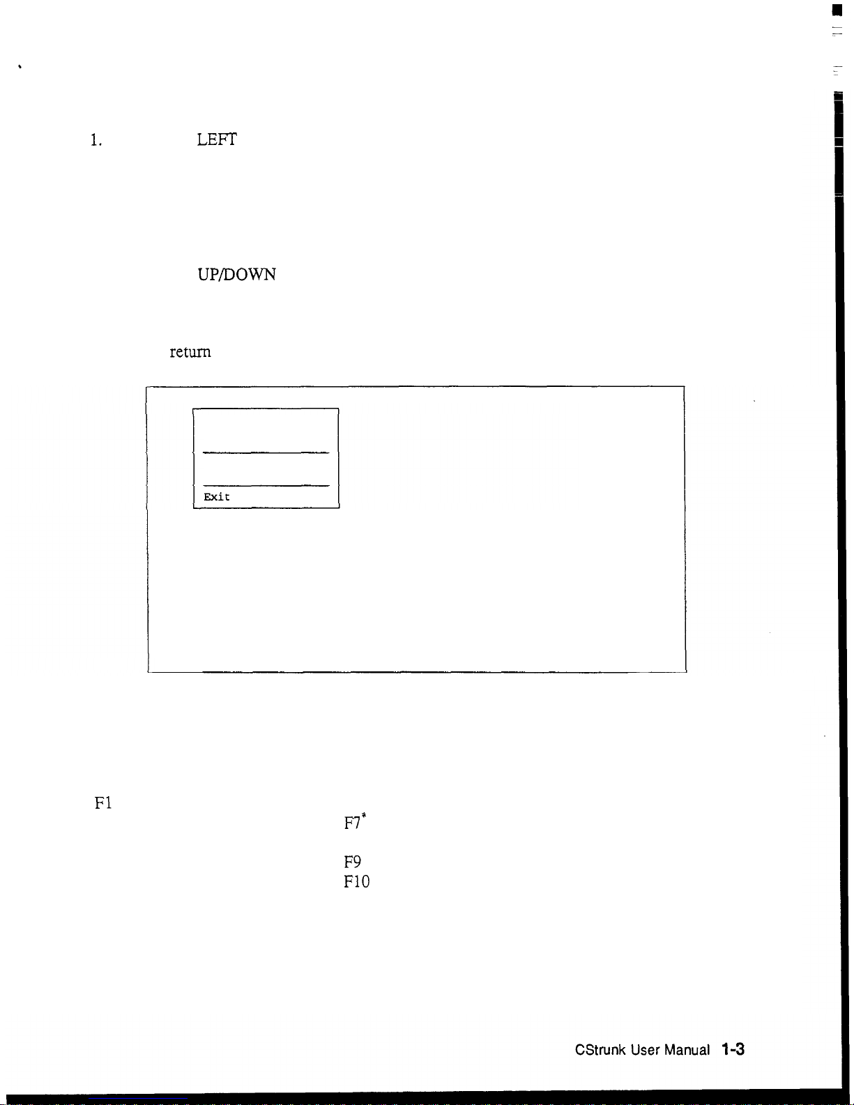
Menu
Selection Using the Computer Keyboard
1.
Use the
LEFT
and RIGHT cursor keys on the computer keyboard to move the cursor
from one menu
to
another on the menu
bar.
The currently selected menu will be
highlighted.
2.
Press the
ENTER
key or
DOWN
cursor key to open the selected menu.
Figure
1-2
shows the opened
File
menu, for example.
3.
Use the UPDOWN cursor keys to highlight a menu item, then press the
ENTER
key
to
select it.
4. Press the ESCAPE key to cancel a selection. Press ESCAPE again to close a menu
and
return
to
the menu
bar.
Help File Trunks Intercoms Status Sort Screen
Log
Options Master
Open Existing File
Create New File
Save
to
File
Clear All Chg Flags
Set All Chg Flags
Exit to
DOS
File: On-Line
Mode:
On-Line
Figure
1-2.
Typical
CStrunk Menu (File Menu Shown)
The function keys
also
drop
down menus from the menu bar as follows:
F1 Help
F2
Files
F3
Trunks
F4 Intercoms
F5 Status
F6
Sort
FV*
Screen
F8
Log
F9
Options
F10
Master
*
This menu is accessible only
during
certain editing procedures.
Page 9
.
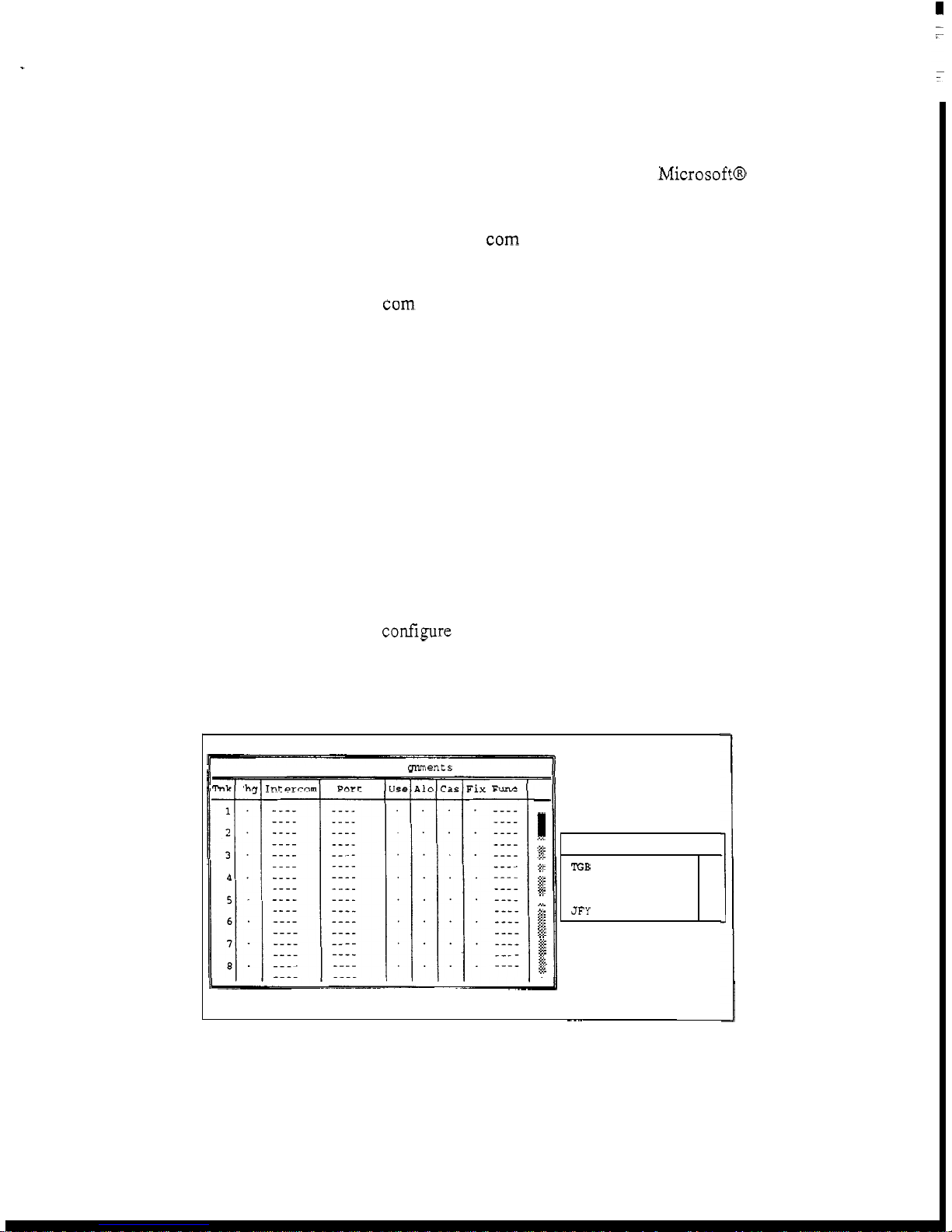
Menu Selection
Using
a
Mouse
You
must install the mouse and its software prior to running CStrunk. Follow the instructions
that came with your mouse. If there
is
a choice, install your mouse as a MicrosoftB
compatible mouse.
Note
If
your mouse does not work, the CStrunk com port setting for communication with
the Trunking Master Controller may be incorrect. (CStrunk may be trying to
communicate with the Trunking Master Controller using the port to which your mouse
is
connected.)
To
change the com port setting, see
Options
Menu,
page
3-4.
To
use a mouse with
CStrunk:
1.
From the CStrunk menu bar, point and click the left mouse button on a menu to open it.
2.
Point and click the left mouse button on a menu item
to
select that item.
3.
To cancel a selection, click on any selectable item with the right mouse button.
To
close
a menu and return to the menu bar, click on any menu item with the right mouse button.
CSTRUNK
EDITING
SCREENS
Figure
1-3
shows a typical editing screen
in
CStrunk.
This
screen contains two windows. The
window at the
left
is
an
edit table to confgure
trunks.
This table has several columns in which
you
enter information to configure the
trunks.
The window at
the
right is a pick list from which
you
can pick items to insert into the edit table
as
you configure the Trunking Master Controller.
Some pick lists open up into sub
lists
when you pick items.
lelp File
Trunks
Intercoms Status Sort Screen
Log
Options
Master
C
.le: On-Line
Trunk
Line Assi m tments
-
I
.....
.....
g:
2:
*
*
$
::.$
*
...
.....
...
.....
.....
.....
>...
in
...
&
3;
...
.A..
,.>
n
.
g.
<.:.
Select Intercom
TGB
JHP
HUB
JPH
JFY
I
Mode: On-Line
~~~
Figure
1-3.
Typical
CStrunk
Edit
Screen
1-4
CStrunk
User
Manual
Page 10
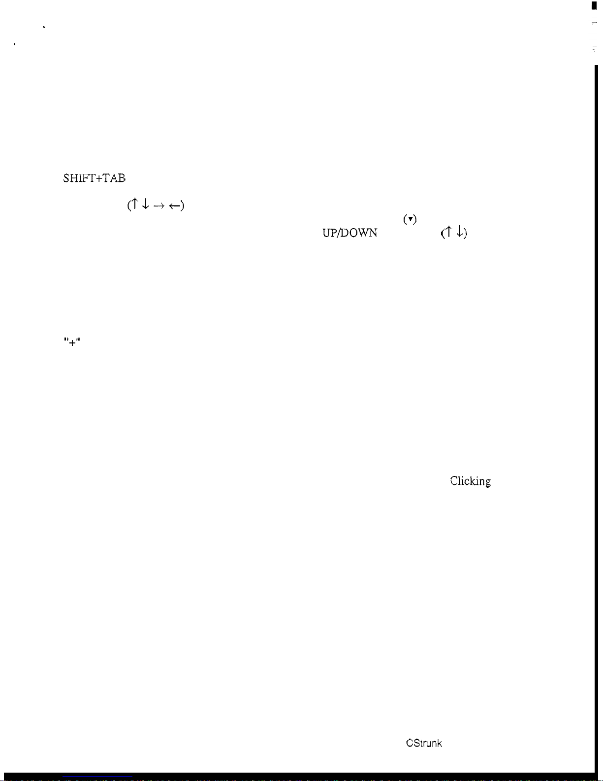
Movement in Editing Screens Using the Computer Keyboard
ESCAPE Key
TAB Key
Exits a sub list or menu item and returns you to the previous
screen.
Moves the cursor from one window to another. The border
around the currently selected window will be highlighted.
SHIFT+TAB Keys Moves the cursor back into the previous window.
Cursor Keys
(T
\1
+
t)
Move the cursor within the current window. Some tables and
pick lists may
also
have scroll buttons
(7)
like the one shown
in Figure
1-3;
use the
UPDOWN
cursor keys
(?
\1)
to scroll
the screen and view additional items.
ENTER Key
Enters information that you have typed into a field, and moves
the cursor to the next field or line. Enters the currently selected
item in a pick list into the currently selected position
in
an
edit
table in another window.
"+'I
key on numeric keypad Inserts
the
currently selected item in a pick list into the
currently selected position in
an
edit table, and then advances
the cursor to the next row
of
the
edit
table.
Movement in Editing Screens Using a Mouse
Click on any item in an edit table to select the edit table. Move the cursor over a pick list to
select it. The border around the currently selected window will be highlighted.
Clicking on an
item
in
a pick list will insert that item into the currently selected position in
an
edit table.
CSttunk
User
Manual
1-5
Page 11
USING
HELP
F1
Key
Calls context
-
sensitive help from within CStrunk. Context
sensitive means the help screens will provide information about
the currently selected menu or menu item.
Key Words
Certain words may be highlighted in a help screen. Select
these words with the
UP/DOWN/LEFT'/RIGHT cursor keys,
then press the ENTER key to get additional help.
are using a mouse, click on the key word for additional help.
Scroll Buttons
Some
help topics may take more than one screen.
will
be
there
screen. When there
cursor keys
a highlighted
is
to
scroll
you are using a mouse.
topic, the cursor
will
scroll
button near the bottom of the
a
scroll
button present, use
down or up.
If
you
Or,
scroll
automatically return to the
click on the
beyond the end of
topic.
BACK SPACE Key Returns you to the previous help screen.
ESCAPE Key Returns you to
CStrunk.
Or,
if you
In
such cases,
the
DOWNNP
scroll
button
the
help
beginning
of
if
the
CREATING/EDITING CONFIGURATION FILES
If the computer is on-line with the Trunking Master Controller when CStrunk is started, the
on
-
line configuration file is automatically opened for editing. To create a new file or edit
existing configuration other than the on-line configuration, select one of two options from the
File menu:
Open Existing File This opens a configuration file that is already on disk.
have done any editing before selecting this option, you will be
prompted to save your work or send it to the Trunking Master
Create New File
Controller before a new file
"
What Would You Like To
Change Flag description, page 1
This clears all settings and creates a blank Trunking Master
is
opened. You will also be asked
Do
With Change Flags". See the
-
8.
Controller configuration. If you have done any editing before
selecting this option, you will be prompted to save your work
or send it to
are cleared. You
Trunking Master Controller before
will
also be asked "What Would You Like
all
the
Do With Change Flags". See the Change Flag description, page
1-8.
an
If
you
settings
To
If, after creating a new file or editing a file on disk, you wish to make changes to the on-line
trunking configuration file, select
1-6
CStrunk
User
Manual
"
Open On-Line" from the "Master" menu.
Page 12

EDITING A CONFIGURATION
Once you have selected one of
the
above file options, you may edit the opened file using the
editing procedures described in Section
2
of this manual.
SAVING YOUR CHANGES
When
you
are
finished creating a new configuration
or
editing an existing configuration, save
your changes using the
"
Save to
File
"
option on
the
File menu.
ACTIVATING A NEW FILE OR SENDING CHANGES
To send your changes to the Trunking Master Controller, use one of two options
on
the
"
Master" menu:
Activate Chgs
Send File
Active only when you have modified the on
-
line file. This
option sends all the changes which have been made since the
last time the file was saved or sent to the Trunking Master
Controller.
Active only when CStrunk
is
in communication with the
Trunking Master Controller, but editing a file other than the
on-line file. This option sends only those items that have
change flags set. To send the entire contents of
a
file, first
select
"
Set All Chg Flags" from the File menu. See the Change
Flag description on page
1-8
for further information about the
use of change flags.
QUITTING CSTRUNK
To quit
CStrunk
when you are finished cditing, select "Exit to
DOS
"
from the File menu and
then press the
ENTER
key.
If
you have not saved
your
changes, CStrunk will
ask
you
if
you
want to do this.
CStrunk
User
Manual
1-7
Page 13

CHANGE
FLAGS
Whenever you open a new file or create a new file, you
will
first
see
the following prompt:
What
would you
like
to
do
with Change
Flags?
Set
All
Chg Flags? Leave Chg Flags? Clear
All
Chg Flags?
Change flags
are
used by CStrunk to determine what items should be downloaded to the
Trunking Master Controller when a file is sent. Only those items that have change flags
turned on (set) will be sent.
Selecting
"
Set All Chg Flags" will
turn
on
all
change flags
in
the
file
that
you
are
currently editing. If you send the file to the Trunking Master Controller after
selecting this option, the current Trunking Master Controller configuration will be completely
overwritten by the new configuration.
Selecting
"
Leave Chg Flags" will leave
all
change flags on that
are
currently
on
and will leave all change flags
off
that are currently
off.
Only those items that have
change flags set would be sent to the Trunking Master Controller during a download,
resulting in only a partial modification of the current Trunking Master Controller
configuration.
Selecting
"
Clear All Chg Flags will turn off
all
change flags in the
file
that you are currently editing. If you then tried to send the file to the Trunking Master
Controller,
it
would have no effect.
As
you make changes to a Trunking Master Controller configuration file, a change flag is
automatically set for each item that you change.
Change flags can be used in three ways to create various configuration changes:
1. If you are on
-
line with the Trunking Master Controller and editing the on-line
configuration, change flags will automatically be set for any items that you change.
Selecting "Activate Chgs" from the "Master" menu will download all items with
change flags set.
2.
If
you want to completely over-write the current Trunking Master Controller
configuration with a new configuration, open the new configuration. file, then select
"
Set All Chg Flags
" . This will assure that all items
in
the file are sent. Now send the
file
using the "Send File" command
on
the "Master" menu.
3.
The "Send File" command can also be used to make periodic updates to the Trunking
Master Controller using files that you prepared previously. Only the items that you
wish to change
will
be sent, which means that updating can proceed much more
quickly than
if
you
send an entire configuration file. Here is how periodic updating
works:
1-8
CStrunk
User
Manual
Page 14

Set up a basic, or starting, Trunking Master Controller configuration.
base this file on a previously existing configuration file by selecting
File
"
Existing
selecting
from the File menu.
"
Create New File" from the File menu. Whichever method you use,
just make sure that you select
Go
ahead and configure the Trunking Master Controller as
Or,
you can make a completely new file by
"
Set All Chg Flags" when prompted.
you
You
"
Open
want it to
can
operate at the start. When your starting configuration is completed, save it to
file. Again, select
"
Set All Chg Flags" when prompted
(in
case you
inadvertently turned off any change flags while editing).
Send your
"
File
configuration to the Trunking Master Controller using the "Send
command in the "Master" menu. Since
all
the change flags are
set,
the
entire configuration file will be sent, and the current Trunking Master
Controller configuration will be entirely overwritten. Your basic configuration
is
now in place.
Prepare your first update file: Using the
"
Save to
File
"
command on the File
menu, save your basic configuration to a new file with a new name. Select
"
Clear All Chg Flags" when prompted.
Go
ahead and make any changes that you want to put into effect during
updating. As you make your changes, the change flags for those items will
automatically be set.
disk,
Again, save your update file to
but select "Leave Chg Flags" when
prompted.
Prepare any additional update files that you need by saving the PREVIOUS
UPDATE FILE with a new name. As before, select
Clear All Chg Flags
"
"
before you start editing the new file, and select "Leave All Chg Flags" when
-
you save or re
open the file.
To send your first update, open the desired update file. Always select
"
Chg Flags
"
Master" menu. Only those items that have change flags set will be sent.
when opening your update files. Then select "Send
Continue to make periodic updates as needed by sending new update files. To
return to your basic configuration at
configuration file to the Trunking Master Controller. Just remember when
opening your basic configuration or
"
Flags
.
File
"
from
any
time, simply send your basic
any
update files, always select "Leave Chg
"
Leave
the
Page 15

SECTION
2
EDITING PROCEDURES
INTRODUCTION
The following editing procedures are arranged in the general order that you would typically
use them when creating a new trunking configuration
file.
ASSIGNING NAMES FOR INTERCOM SYSTEMS
From the Yntercomsl' menu, select "Names". The edit screen for intercom names should
-
appear (Figure 2
Controller,
combination of up to four characters.
1). Up to 12 intercom systems can be connected to the Trunking Master
so
CStrunk lets you assign
up
to 12 intercom system names. Names can be any
Note
The "Icm" numbers are not the actual hardware ports on the Trunking Master
Controller. They are just arbitrary numbers that CStrunk associates with each
intercom name.
As
you will see in a moment, any intercom name can be "mapped
to any port of the Trunking Master Controller. For now, enter names of intercom
systems in any order that you wish.
Help File
:ile: On-Line
Trunks
Figure
Intercoms Status Sort Screen Log Options Master
11
Intercom Names
~
8
10
11
12
2-1.
Intercom Name Assignment
11
Mode: On-Line
"
Page 16

ASSIGNING INTERCOM SYSTEMS TO PORTS
OF
THE TRUNKING
MASTER CONTROLLER
1.
From the "Intercoms" menu, select "Setup". The port setup screen should appear
(Figure
2-2).
For each intercom system that you have
named,
position the cursor in
the
"
Baud" column, and press the SPACE BAR to set the baud rate. The default
baud rate for
all
intercom systems is
76.8K
baud.
9600
baud should only be
selected when a port
of
the Trunking Master Controller is linked to a remote
intercom system over a modem.
2.
For each intercom system, position the cursor in the "Port" column,
and
enter the
actual hardware port number that the intercom system is connected
to
on the
Trunking Master Controller.
Note
CStrunk
will not allow
you
to assign the same port number to more than one
intercom system.
To
erase a port assignment
so
that it can be used elsewhere,
position the cursor over the port number and press the SPACE BAR.
In
the
example below, the Port
8
assignment was erased from Icm
8
so
that it could be
used for Icm
5.
Help
File
Trunks
Intercoms Status Sort Screen Log Options Master
Intercom Setup Data
Changed
4
11
File: On-Line Mode: On-Line
Figure
2-2.
Intercom Port Setup
2-2
CStrunk
User
Manual
Page 17

DOWNLOADING PORT ASSIGNMENTS AND VERIFYING
CONNECTIONS
1.
From the "Master" menu, select "Activate Chgs".
2
Verify that
all
defined matrices are now communicating with the Trunking Master
Controller: From the
"
Status
"
menu, select "Intercom". The status screen should
display the type and
status
of each connected intercom system (Figure
2-3).
In
the
example,
all
defhled intercom systems except
HUB
are
now conlnlunicating
with
the Trunking Master Controller. Possible causes
of
a "Bad
Off'
indication are an
incorrect port assignment, an incorrect baud rate setting, a deactivated intercom
-
system, or a disconnected/miswired cable from the intercom system to
Trunking Master Controller.
Help
File
Trunks
Intercoms
Status
Sort
Screen
Log Options
Master
i
Icm
Confiauration
1
8
10
9
11
'ile:
On-Line
Alpha
Ok
CS9700
Ok
CS9600
Bad Off
Ok
CS9500
Ok
CS9500
Bad Off
Bad
Off
Bad Off
Bad Off
Bad Off
Bad Off
Bad Off
Mode : On-Line
Figure
2-3.
Verifying Intercorn System Status
the
CStrunk
User
Manual
2-3
Page 18

*
DEFINING THE TRUNKS
1.
From the "Trunks" menu, select "Defs for
All"'.
The Trunks pick list should
appear (Figure
2-4).
You
can define up to
999
trunk
lines.
In
actual practice,
however,
you
will probably never use more than
50-100
maximum. The
trunks
have been divided into blocks of
50
for convenience. Selecting "Trunks
1
-
50
"
will cause a setup screen for these trunks to appear
(Figure 2-
5).
Help File
Trunks
Intercoms Status Sort Screen Log Options Master
I
For
All Intercoms
Trunks
1
-
50
Trunks
101
-
150
Trunks 151
-
200
Trunks 251
-
300
Trunks
Trunks 51
-
100
Trunks
201
-
250
Trunks
301
-
350
Trunks
351
-
400
Trunks
401
-
450
hunks
451
-
500
Trunks
551
-
600
hunks
601
-
650
hunks 651
-
700
Trunks 701
-
750
hunks
751
-
800
Trunks
501 - 550
Trunks
801 - 850
?ile: On-Line
1
Mode: On-Line
Figure
2-4.
The Trunks Pick List
Trunk
Line
Assi
gr
tle: On-Line
unencs
II
Help File
Trunks
Intercoms Status Sort Screen Log Options Master
T
-
...
...
.:.;
...
n..
.....
.:.:.
.:.:.
...
i.i
28
:s
*
3:
*
...
i...
.;.:.
:.:.:
.....
.....
.:.:.
x.:
..
.
.....
i...
.A_..
2:
0'
.:.:.
11
Mode: On-Line
Select Intercom
JH
P
Figure
2-5.
The Trunking Assignment Screen
1
If you had already defined some
trunks
and now wished to
edit
the
trunks
to/from a
particular intercom system, you could select
"
Defs for Icom
"
from
the "Trunks" menu
instead
of
"
Defs for All".
2-4 CStrunk
User
Manual
Page 19

Note
The following steps define a method for setting up
trunks
using the pick lists for
the various intercom systems. This is only a suggested method.
In
actual practice,
you could also type in the names and port numbers to define
trunks
if
you wished.
In
order to set up the
trunks,
you will need to have a list of the audio ports that
have been interconnected between the various intercom systems.
2.
Define one end of the first
trunk:
a) Position the cursor in the "Port" column for
Trunk
#l.
b) TAB to the matrix pick list at the right side of the screen, and select the
matrix where the port is located (or click on a matrix with a mouse).
In
the
example in Figure
2-6,
matrix "TGB" has been selected, and the pick lists
for that intercom system have been uploaded. Since
trunk
lines are always
connected to ports, you would select
"
Ports
"
to
get a pick list of ports for
matrix
"
TGB" (Figure
2-7).
Help File Trunks Intercoms Status Sort Screen Log Options Master
-I1
File: On-Line
ssignments
I
.....
.....
...
...
.....
.....
.....
...
.....
.....
.....
...
I,
Mode: On-Line
I
Figure
2-6.
Pick
List for Matrix
"
TGB
"
CStrunk
User
Manual
2-5
Page 20

3.
c> When you select a port and press the
ENTER
key (or click on a port with
a mouse)
CStrunk
automatically inserts the intercom system and port
number into the
trunk
assignment table.
In
the example in Figure 2-
7,
port
NO01
was selected.
Press
the
ESCAPE
key twice to close the
"
Ports
For
TGB
"
pick list and return to the "Select Intercom" pick list.
Help File
Trunks
Intercoms Status Sort Screen Log Options Master
Trunk
Line
Assior
Chg
I
Int ercon
11
File: On-Line
NO01
NO
02
NO
03
NO04
NO05
NO06
NO07
NO09
NO10
NO11
NO12
NO13
NO14
NO15
NO1
6
I
Figure
2-7.
Defining the First End
of
a
Trunk
Define the other end
of
the first
trunk.
Position the cursor
in
the "Ports" column
directly under the first assignment, then select the port on the second intercom
system
to
which the first intercom system port is connected.
In
the
example in
Figure
2-8,
port
NO15
on matrix "JHP" was selected.
Help File
Trunks
Intercoms Status Sort Screen
Log
Options Master
I
File: On-Line Made: On-Line
Figure
2-8.
Defining the Second End
of
a
Trunk
2-6
CStrunk
User
Manual
Page 21

4.
Specify whether or not you want the
cascaded by positioning the cursor
BAR to place a check mark
4
in
trunk
to be cascadable.
in
the "Cas" column and pressing the
A
,trunk
can be
SPACE
the column. Cascading provides a means for two
intercom systems to communicate with each other even when there is no
interconnecting
intercom systems, the
trunks
both intercom systems have
may be cascaded through the other intercom systems
trunk
lines to other
trunk
line.
If
as required to provide a communication path. An example of the use of cascaded
trunks
matrix
"
is
shown
"JFY";
in
Figure
2-9.
Note that matrix "TGB" has no direct connection to
however, a path can be "cascaded" through matrix
"JHP"
HUB" to provide communication between matrix "TGB" and matrix
and matrix
"
JFY".
If
the
cascade flag was not set for any one of the matrices shown, no communication
would be possible between the two end points. One drawback of cascading is that
multiple
trunks
are required to support a single conversation.
Help File
II
-
:ntercom
File: On-Line
Figure
Trunks
hunk
Intercoms Status
Line Assianments
Port
2-9.
An
Example
Sort
of
Screen
>g
-
7
-
I
&
NO04
:.:.:
:g
NO05
:x.:
.?..
NO06
:.:e
P...
NO07
.>:.
g
NO09
..
.....
.....
.:.:.
:.:.:
*.
p
6;:
>.,
.&<
NO13
3:s
,...
".
.....
<.:.
%
e
Cascaded
options Master
Ports
For JFY
Mode: On-Line
Trunks
Page 22

5.
Specify whether you want an end of a trunk to be fixed to a port, party line etc. In
the example in
"1DIR" on matrix
"
matrix
anyone else using
JFY".
Figure
Note that this trunk is not cascaded because
2-10, one end of trunk
"
HUB";
it.
the other end has been fixed to party
#4
has been fixed to
the
line
"PL07"
you
would not want
port called
on
Note
Help File
Ilmklc
1
7
File: On-Line
Figure
The "Use" and "Alo" columns are not assigned by you when setting up trunks.
These columns are used to provide trunk status information during operation. See
Checking Trunk Status, page 2-9.
F
2-10.
Trunks
Intercoms Status Sort Screen Log Options Master
Trunk
Line
An Example
Assignments
lse
Alc
~
of
"
3x
Func
a Trunk with Both Ends Fixed
1
-
-
PL
-
1
2
3
4
5
6
7
9
11
$2
.$<
:.:.:
.>:.
x.:
$3
:.:.:
.....
:.:.:
.:.:.
10
11
12
.:.:.
:.:.:
<.:.
13
:s
14
8
:s
15
:+:
16
-
d
Mode: On-Line
6.
2-8
Set the trunking timeout. Press ESCAPE as required to return to the menu bar.
Then, from the
screen will appear (Figure 2-1
amount of time that a trunk will remain allocated to a user after that person stops
using the trunk. After the timeout period, the trunk becomes available for anyone
to use. The default timeout period is
User
from
Manual
period
CStrunk
"
Trunks" menu, select "Options". The "Trunk Allocation Timeout
1).
The number you enter here determines the
15
seconds. This may be changed to any
0-99 seconds.
"
Page 23

I
Help File Trunks Intercoms Status Sort Screen
Log
Options Master
File: On
-
Line
Mode:
On-Line
Figure
2-11.
The Trunking Timeout Screen
7.
Send the changes to the trunking master. From the "Master" menu, select "Activate
Chgs
"
.
8.
Be
sure
to
save
your
file
to
disk using "Save to
File" on the
"
File
"
menu.
CHECKING TRUNK STATUS
To
check
trunk
status, select "Defs for All" or "Defs for Icom" from the "Trunks" menu. The
current status of each trunk
is
indicated in the "Use" and "Alo" columns as follows:
"
Use" Column: A check
mark
is placed in this column by CStrunk during
operation to indicate that the
trunk
is
in
use. While the Trunk Line Assignments
Window is highlighted, the user may press
the
ENTER
key to get updated
information.
(To
see who
is
using a
trunk,
run CSedit and open the key
assignments table for the port being used for the
trunk. To
update the key
assignments table, select
"Cancel Screen Changes" from the "Screen" menu.)
"Alo" (allocation) Column: A check mark is placed in this column by CStrunk to
indicate that the
trunk
is allocated, whether or not it is
in
use. A
trunk
will tend to
remain allocated to the last user. However, if the
trunk
is not in use and the
timeout period has expired, the
trunk
will be available for general use.
CStrunk
User
Manual
2-9
Page 24

SECTION
3
REFERENCE
I
Note
This section contains additional'inforrnation about
CStrunk
features that may be
of
interest to some users. Topics in this section are arranged in alphabetical order.
CHANGING SCREEN COLORS
Note
There are several reasons why you may wish to change the default screen colors for CStrunk:
a
0
0
Here is how to change the screen colors:
If you have already created a customized color scheme for CSedit, you
same color scheme for CStrunk by copying the
CSEDIT.SET file to a
may
file
use the
named
CSTRNK.SET in the CStrunk directory.
YOU may have a laptop computer which maps colors to shades of grey, and the screen
is unreadable.
You may have more than one intercom, and you wish to distinguish which one you
working with by the screen colors.
are
You may prefer different color choices.
1.
Note
Using a DOS text editor, open the CSTRNK.SET file in the CStrunk directory.
If there is no CSTRNK.SET file, you can create one by running CStrunk and
temporarily changing the baud rate setting as described on page
the Options menu, CStrunk will create the
You
can now restore the original baud rate setting.
2.
The CSTRNK.SET file contains 28 lines of numbers. Lines
-
number; lines 4
28 each contain three numbers separated by single spaces. The first
two numbers (foreground and background color) are used when line 3 is set to
(Automatic). The last number is used when line 3 is set to
function of each line is described in Table
corresponding values are listed in Table 3
CSTRNK.SET file to create the color scheme that you want.
3.
After
you
have created the desired color scheme, save the file as a plain ASCII file.
4. Run CStrunk and check the color scheme.
3-5.
When you exit
CSTRNK.SET file in the CStrunk directory.
1-3
each contain one
"0"
"1"
(Force Mono). The
3-1.
Available colors and their
-
2. Change the values in each line of the
Page 25

Table
3-1.
CSTRNK.SET
File Line Usage
Line# Use Settings Default
Value
Baud Rate
0=9600, 1 =38.4K, 2=19.2K 2
Communications
Port
O=COMl
,
1
=COM2
0
l3
ColorMono Select O=Automatic, 1 =Force
Monochrome
Lines 4
-
7 set the colors in the menus:
4
Unselected menu items See Table 3-2 1370
5
Selected menu item See Table 3-2 7
1
Of
6 Menu bar See Table 3-2 e 3 70
I
Unselectable menu item’
I
See Table 3-2
Lines 8
&
9 set the colors in the error messages:
I
9370
I
II
a
-
I
Error messaae
1
See Table 3-2
I
f
4 07
11
11
9
I
Error message border
I
See Table 3-2
I
f
c f7
II
~~ ~
Lines 10 -~20 set the colors
in
the editing windows:
10 Regular field, edit window See Table 3-2
f
1 Of
11 Selected field. edit window See Table 3-2
f
3 70
11
12
I
Background (non field), edit window I See Table 3-2
1
7 107
11
13 Border, current window
14 Border, non current window See Table 3-2 2
1
07
15 Selected field, non-current window See Table 3-2
f
3 70
16 Restricted field See Table 3-2 c
1
07
~~ ~~~~
See Table 3-2
f
1
Of
”
17 Selected restricted
See Table 3-2
~
4307
~
18 Non-editable field
See Table 3-2
a
1
07
19
Invalid field
See Table 3-2
e
1
07
20 Selectable invalid field
See Table 3
-
2 e 3 07
II
Lines 21 - 24 set the colors for the overall screen:
II
It
21
I
File/on-line status line
I
See Table 3-2
I
1 3 70
11
II
22
I
Bottom status line
I
See Table 3-2
i
7 107
II
I
23 Background
See Table 3
-
2
1
1
07-
-’
24 Background selected field
See Table 3
-
2
1
1
07
Lines 25
-
28 set the colors in the help screens:
25 Help background See Table 3
-
2 7 1 07
26 Help key words See Table 3
-
2 e
1
Of
27 Help selected key word See Table 3-2 e 3 70
28 Help border See Table 3
-
2 7 1 07
The Screen menu, for example, when no edit screen is open,
.
-
Page 26

Table
3-2.
Color
Chart
Foreground Color
Background Color
(First Number)
(Second Number)
0
black
0
black
1
blue
1
blue
2
green
2
green
3
cyan
3
cyan
4
red
4
red
5
magenta
5
magenta
6
brown
6
brown
7
white 7 white
8
dark grey
8
black, blinking
9
light blue
9
blue, blinking
a light green a green, blinking
b light cyan b cyan, blinking
c light red c red, blinking
d light magenta d magenta, blinking
e light yellow e brown, blinking
f
bright white
f
white, blinking
Example:
5
1
70
=
magenta foreground, blue background, r(
Monochrome Setting
(Third Number)
07 normal
70 reverse
Of
bold
f7 blinking
01 underline
09
bold underline
fl
blink underline
fO
blink reverse
verse in monochrome
COPYING AND PASTING EDIT SCREENS
You
will probably not copy any screens in CStrunk; however, the procedure is the same for
CStrunk as for CSedit. For further information about copying and pasting screens, see this
topic in the CSedit manual.
CSTRUNK
FILES
The following files are supplied on the CStrunk disk.
$$STALL.EXE Used to install CStrunk on
your
hard drive.
INSTALL.BAT
README.TXT Release notes
for
CStrunk.
CSTRNKEXE The CStrunk program file.
CSTRNK.HLP The help file for CStrunk (must be in the CStrunk directory)
Any time you change any settings in the Options menu, CStrunk creates
an
additional file,
called CSTRNKSET, in the directory where CSTRNKEXE
is
located.
You
can use a text
editor to customize the color settings in
CSTRNKSET. See
Changing
Screen
Colors,
page
3-1.
CStrunk User Manual
3-3
Page 27

LOG
MENU
(F8
KEY)
Logging
is not implemented in the current version of CStrunk.
OPTIONS
MENU
(F9
KEY)
The Options menu
(Figure 3-
1)
contains options for screen colors and communication
settings. Use the
LEFTNGHT
arrow
keys on the computer keyboard to highlight "Options",
then press
the
ENTER key to open the menu. Use the
UPDOWN arrow
keys to select the
desired option, then press ENTER again. For information about the color settings, see
Options,
Color,
below. For information about
COM
port and baud rate settings, see
Options,
Communications,
page
3-5.
Help File
hunks
Intercoms Status Sort Screen Log options Master
Communications
File: On-Line Mode : On-Line
Figure
3-1.
The Options Menu
Options, Color
When you select "Color" from the Options menu, the "Color and Mono Setup" screen will
appear (Figure
3-2).
Press the SPACE BAR on the computer keyboard to select "Automatic
"
for color operation or "Force
Mono
"
for monochrome operation.
"
Automatic" detects the presence of a color adaptor (CGA, EGA, VGA) and sets up screen
colors for color operation.
"
Force Mono" ovenides automatic color setup and forces
monochrome (black and white) operation. Force mono is the correct choice,
for
example, with
many laptop computers that have a monochrome LCD display.
The CStrunk color selection is saved in a file called
CSTRNK.SET, (located in the same
directory as the CStrunk program). When you change
the
color option and press ESCAPE,
CSTRNK.SET is automatically updated.
Note
For color operation, you can customize the colors used by CStrunk. See
Changing
Screen
Colors,
page
3-1.
3-4
CStrunk
User
Manual
Page 28

IMPORTANT:
IF
YOU
HAVE A CGA MONITOR.
Do
not select "Force
Mono
"
unless you know that your computer also supports monochrome
operation. Most CGA machines abort when forced
to
monochrome.
If
you select "Force
Mono
"
and the computer aborts, proceed as follows:
1.
Reboot the computer, but do not run CStrunk.
2.
Erase the file CSTRNK.SET.
3.
Run CStrunk. CStrunk will revert to the default color selection.
NOTE TO LAPTOP COMPUTER
USERS
Many LCD laptop computers emulate the CGA video interface. The important note above
applies to most of these machines as well.
A
further consideration is that many of these
machines map color selections to grey
-
scale values. There are
no
standards for this mapping,
so
on
some machines, the standard CStrunk color scheme will not be readable. If this is the
case, you may have to make changes in the
CSTRNK.SET
file. See
Changirzg
Screen
Colors,
page
3-1.
Help File
Trunks
Intercoms Status Sort Screen
Log
Options Master
A
Color
and
Mono Setup
Color/Mono Mode: Automatic
Mode: On
-
Line
Figure
3-2.
Color / Monochrome
Setup
Screen
Options, Communications
This menu item
is
used to set the comm port and baud rate for communication between the
computer and the Trunking Master Controller. If the computer cannot get on
-
line with the
Trunking
Master Controller, check the comm port and baud rate settings as follows:
comm
Port
1.
From the Options menu, select Tommunicationstt. The communications setup screen
should appear (Figure
3-3).
CStrunk
User
Manual
3-5
Page 29

~
Help File
T-S
Intercoms Status Sort Screen
Log
options Master
i
I
!
/File: On-Line
i
I!
Baud Rate:
19.2K
1
ii
Corn Port:
COM2
1,
!;
I
,
Mode: On-Line
Figure
3-3.
The Communications Setup Screen
2.
Select "COMl", then press the SPACE BAR (or click with a mouse) to change
TOM1 to "COM2" (or vice versa).
3. Press the ESCAPE key. After a few moments, the message
"
Uploading data" should
appear in the lower
-
left comer of the CStrunk screen, and "On-line" should appear in
the lower
-
right side of the screen.
If
this does not happen, the cable from the computer
to the Trunking Master Controller may be incorrectly wired. See
Appendix
A
for
information about cable wiring.
Note
If
you
are using a mouse, you must exit CStrunk and restart the program to re-
initialize the mouse. Use the LEFTRIGHT mow keys on the keyboard to select the
"File
"
menu on the menu bar. Use the DOWN arrow key to open the menu and select
"
Exit to
DOS".
Then press ENTER. When
you
restart CStrunk, the mouse should be
operational.
Baud Rate
Three baud rates
are
available: 9600 baud, 19.2K baud and 38.4K baud. 19.2K baud is the software
default for
CStrunk.
This
is
also
the hardware default for the FR9589 Master Control Unit.
If
operation at 9600 baud or 38.4K baud is desired,
the
DIP switches must
be
reset on the bottom IOU
board
in
the FR9589. Refer to the FR9589 Drawings Manual for location and settings of the
DIP
switches.
Operation at
19.2K baud allows the use
of
medium-length cable (up to about
50
ft,
or 15 m), and
results in
medium-speed communication between the computer and the Trunking Master Controller.
Operation at 9600 baud allows the use of
a
longer cable, but results in slower communication
between the computer and the Trunking Master Controller. The parameters for operation at
9600 baud are: no parity, 1 stop bit,
8
data bits, 1 start bit,
9600
baud.
38.4K baud results in fastest operation, but requires a short cable from the computer to the
Trunking Master Controller (less than 10
ft,
or 3 m).
Also,
the serial port on some computers
may not support operation at this speed.
3-6
CStrunk
User
Manual
Page 30

a
SCREEN MENU
The Screen menu is generally selectable only when an edit screen is currently open (for
example the trunking assignment screen).
(F7
KEY)
Screen, Cancel Screen Chg
If editing a file other than
settings in the currently opened edit screen to be restored to the settings when the screen was
entered.
the
on-line file, selecting "Cancel Screen Chgs" will cause all
Screen, Paste Screen
"Paste Screen" is selectable only after
Selecting
screen. All settings for all items in the copied screen will be pasted.
"
Paste Screen" will cause the copied configuration to be pasted
an
edit screen has been copied using "Copy Screen".
to
the current edit
Screen, Copy Screen
Topy Screen" will copy the entire configuration for the current edit screen, including the
settings for
STATUS MENU
To access all items on this menu, the computer must be connected
Controller, and the on-line file must be opened in CStrunk.
all
items
in
all windows not currently opened.
(F5
KEY)
to
the Trunking Master
Status, Intercom
When you select
this
item, you will be presented with the intercom status screen (Figure
3-4).
CStrunk
User
Manual
3-7
Page 31

Help File
hunks
Intercoms Status Sort Screen
Log
options Master
IFile: On-Line Mode: On-Line
Figure
The information displayed
3-4.
Typical Intercom Status Screen
in
the "Config" column indicates intercom status as follows:
I
Bad Off Indicates that there has never been any data communication with this intercom
system during the current edit session. Possible causes of a
indication are
"
menu,
Setup"), a deactivated intercom system, or a disconnected/miswired
an
incorrect
port
assignment or baud rate setting (Intercoms
"
Bad Off
"
cable from the intercom system to the Trunking Master Controller,
Bad Cut Indicates that there was an intercom system at the port at some time during the
Ok
CS9
...
current edit session, but
Indicates that an intercom system
followed by a question mark
it
is not now transmitting data.
is
connected and transmitting data.
(?),
this indicates that the intercom system
If
"Ok"
is
controller has an earlier version of software.
Status, Standby
TM
When you select this item, you will be presented with the status screen for the Standby
Trunking Master Controller (Figure
3-8
CStrunk
User
Manual
3-5).
Page 32

Stby
TM
Configuration
I
Stby
TM
I
Config
I
I
Help File
hunks
1nr;ercoms Status Sort Screen Log Options Master
File: On
-
Line Mode: Gn-Line
Figure
3-5.
The Standby Trunking Master Status Screen
The information displayed in the "Config" column indicates status as follows:
Bad Off Indicates that there has never been any data communication with a standby
trunking master during the current edit session. This could be because the
device is not connected or has not been turned on.
Bad Cut Indicates that there was a data device at the port at some time during the
current edit session, but
it
is
not now transmitting data.
Ok
Cur Indicates that the standby trunking master is connected and operating, and that
it has been updated with the current Trunking Master Controller configuration.
Ok
Old Indicates that the standby trunking master
is
connected and operating, but that
it
has not been updated with the current Trunking Master Controller
configuration.
Ok
?
Indicates that the device
is
a standby trunking master with an earlier version of
software.
Status,
Diagnostics
Page 33

1
Help File Trunks Intercoms Status Sort Screen Log Options Master
i
Select Diagnostic Type
~~
!
!
i
1
File: On-Line Mode: On-Line
Figure
3-6.
The CStrunk Diagnostics Selection Screen
Diagnostics, CStrunk Version
This manual documents version 7 of the CStrunk software.
Diagnostics,
TM
Version
This selection indicates the version number
of
the
ROM
in the Trunking Master Controller.
Diagnostics, Comm Error Screens
When
you
select any
of
the
corn
error
items, a screen similar
to
Figure
3-7
will appear.
This particular screen shows communication errors between the Trunking Master Controller
and each intercom system.
~
Help File Trunks Intercoms Status Sort Screen Log Options Master
i/
TM
<=>
Intercom
Comm
Errors
-
/I
'jIcom
~
Description
'
Err
BER
Err
BER
1
I
i
-
,Msgs
From Icom *Msgs
To
Icom
'0
0
0
0
0
:o
0
!O
0
0
0
:o
0
0'
0
0
0
0
0
0
0
0
0
0
0
0
0 0
0;
0
0:
0
01
0
0; 0
File: On-Line Mode: On-Line
~ ~~~
Figure
3-7.
Typical Communication Error Screen
3-10
CStrunk
User
Manual
Page 34

Errors
are
listed separately for communication from the intercom system to the Trunking
Master Controller and from the Trunking Master Controller to the intercom system. Two
types
of
errors
are
listed: the total accumulated errors are listed in the "Err" column; the bit
error rate is listed in the
"
Ber" column. The bit error rate is the number
of
errors during the
last ten minutes of operation. All counters are reset to zero on reset or power
-
up
of
the
Trunking Master Controller. All counters may be updated by pressing the ENTER key while
viewing the screen.
In
general, error rates of no more than one error per hour
are
normal. Error rates between one
per hour and one per minute are higher than normal but may not cause significant problems.
Error rates greater'than 1 per minute usually require immediate attention.
Systems installed in facilities with good grounding, using high quality telephone type twisted
pair wiring will normally operate with error rates between 0 and
20
per
24
hours. With
shielded wire, the rates are generally higher, because of the additional cable capacitance
(5-30
per
24
hours). Symptoms
of
higher error rates begin to appear when the rate exceeds 1 per
minute. Symptoms include cross points which remain closed for no apparent reason,
IFB's
with muted program when no keys are closed, slow response (especially to keypad), and
general inconsistent or
"
flaky" operation. General causes
of
high error rates include:
Cables too long
Poor facility grounding practices
0
Crosstalk, especially when using non-twisted wiring, with long parallel runs
of
data
cables
in
close proximity to each other containing differing data streams.
Noise Induction: intercom data cabling running parallel to lighting cables etc.
0
One side
of
a data line shorted
to
ground or audio
CStrunk
User
Manual
3-11
Page 35

APPENDIX
PC
to
Trunking Master Controller Interconnect Cable Wiring
9-PIN
TO
25-PIN
CABLE
TO TRUNKING
SYSTEM TO COMPUTER
---
-
I
-1
I
----
-
I
I
RX2<1
I I
:
(2TX
I
1
TX3<;
I
I
I
(3RX
I
I
I
GND5(1
I I I
(7GNDl
I
I I
I
I
I
I
I
I
1
I
I
I
I
I
I I
t----J
9-PIN MALE 25-PIN FEMALE
L----J
CONNECTOR CONNECTOR
9-PIN
TO
9-PIN
CABLE
TO TRUNKING
SYSTEM
TO
COMPUTER
-----
I
I
I
RX2<{
I
-
I
I
I
I
TX3<;
I
I
(3TX
I
I
I
I
GND5(,
I
I
(5GNDI
I
I
I
I
1
I
I
I
I
I
I
I
I
I
I
I
t----J
9-PIN MALE
L----J
9-PIN FEMALE
---
-
I
(2RX
I
I
CONNECTOR CONNECTOR
CStrunk
User
Manual
A-I
I
 Loading...