

Page 1

TM
ADAM
Advanced Digital Audio Matrix
USER MANUAL
CSedit
Intercom Configuration Software for
ADAM and ADAM CS
Intercom Systems
9350-7077-300RevC,8/00
™
Page 2

CONTENTS
Introduction iii
If You Are in a Hurry! iii
Version Number iii
Computer Requirements iii
Use of Special Type Styles in this Manual iii
Section 1: Getting Started
Installing CSedit 1-1
Starting CSedit 1-1
CSedit Start-up Routine 1-1
CSedit Menu Screen 1-1
Menu Selection Using the Computer Keyboard 1-2
Menu Selection Using a Mouse 1-2
CSedit Editing Screens 1-3
Movement in Editing Screens Using the Computer Keyboard 1-3
Movement in Editing Screens Using a Mouse 1-3
Using Help 1-3
Creating / Editing Configuration Files 1-4
Editing a Configuration 1-4
Saving Changes 1-4
Activating a New File or Sending Changes 1-4
Quitting CSedit 1-4
Change Flags 1-4
General Description 1-4
Change Flag Prompt when Opening or Saving a File 1-4
Uses of the Change Flags 1-5
Section 2: Editing Procedures
Introduction 2-1
General Procedure to Configure the Intercom System 2-1
Additional Requirements for Trunked Intercoms 2-1
Assigning Names (Alphas & Aliases) 2-1
General Description 2-1
Naming Individual Audio Ports 2-1
Naming Other Types of Communication (Party Lines, ISO’s etc.) 2-2
Creating a Party Line 2-3
Creating an IFB ( Interrupt Foldback Bus) 2-6
Creating a Special List 2-8
Using Relays 2-11
Creating a Camera ISO Channel 2-13
Keypanel Setup and Trunking Port Allocation 2-15
CSedit User Manual i
Page 3

Keypanel Setup: Selecting a Keypanel For Editing 2-15
Keypanel Setup: The Setup Table 2-17
Keypanel Setup: Key Assignments and Key Restrictions 2-17
Keypanel Setup: Using the Pick Lists 2-18
Keypanel Setup: Special Functions 2-18
Keypanel Setup: Using Copy Screen and Paste Screen 2-19
Keypanel Setup: Port Information 2-20
Keypanel Setup: Data Changed Window 2-21
Understanding How MODS Work 2-22
Section 3: Reference
Introduction 3-1
Changing Screen Colors 3-1
CSedit Files 3-2
Copying and Pasting Edit Screens 3-2
Using Search (Keys Menu) 3-2
Moving a User to a New Port 3-2
Options Menu (F9 Key) 3-5
Options, Color 3-5
Options, Communications 3-6
Remote IFB 3-7
Screen Menu (F7 Key) 3-8
Screen, Cancel Screen Chg 3-8
Screen, Paste Screen 3-8
Screen, Copy Screen 3-8
Speed Formatting 3-8
Status Menu (F5 Key) 3-9
Status, Port 3-9
Status, Standby Controller 3-10
Status, Trunk Master 3-11
Status, PAP 3-12
Status, UIO-256 3-13
Status, Diagnostics 3-14
System, Digital Inputs 3-15
System, Force & Inhibit 3-16
General Usage 3-16
Typical Application of Forced Crosspoint 3-17
System, Special Functions 3-18
Appendix
PC to Intercom System Interconnect Cable Wiring for ADAM Intercom A-1
PC to Intercom System Interconnect Cable Wiring for ADAM CS Intercom A-2
Index I-1
ii CSedit User Manual
Page 4

Introduction
Computer Requirements
This manual describes the CSedit Intercom Configuration Software for the ADAM
com Systems. The manual is divided into three sections.
Section 1, “Getting Started”, briefly describes basic
CSedit operation. Section 2, “Editing Procedures”, provides step-by-step procedures for the most commonly
used features of CSedit. Section 3, “Reference”, provides additional information about CSedit features.
TM
and ADAMTMCS Inter-
If You Are in a Hurry!
If you wish to run CSedit immediately, simply insert the
CSedit disk in your computer, type csedit, and press the
ENTER key. If you encounter problems while using the
CSedit menus, press the F1 key on your computer keyboard to access the CSedit on-line help.
Version Number
The CSedit version number should be imprinted on the
software diskette. CSedit and master controller version
numbers are also available while running CSedit (see
“Status, Diagnostics”, page 3-14.)
An IBM® orcompatible personal computer with at least 2M
of extended memory (4M recommended). CSedit cannot be
run under any other operating system other than DOS.
A Microsoft® serial mouse (optional). Two serial ports
are required for use with a mouse, with COM1 as the default port for the intercom system connection.
Use of Special Type Styles in this
Manual
Certain type styles which appear in the text of this manual
(not in titles) have special meanings as follows:
Bold in Text : Anything you must type
Italics in Text : References to other manuals
ALL CAPS IN TEXT: Directory names, filenames and
names of keys on a computer keyboard
Initial Caps In Text: References to CSedit menus, menu
items, tables and lists
CSedit User Manual iii
Page 5

This page intentionally left blank.
iv CSedit User Manual
Page 6
Section 1: Getting Started
Installing CSedit
Note The default port for communication between the
computer and intercom system is COM1 and
9600 baud. If the intercom system configuration
does not upload, you may have to change these
settings. See "Options Menu", page 3-5.
The minimum requirement to run CSedit is a 386 c omputer with at least 2M of extended memory (4M preferable). Also, CSedit should not be installed to run under
any other operating system other than DOS.
To install CSedit: insert the CSedit disk, then change to
the drive where the disk is inserted. Type install and
press the ENTER key.
Store the original disk in a safe place.
Starting CSedit
Change to the drive and directory where the CSedit files
are located. Type csedit, then press the ENTER key.
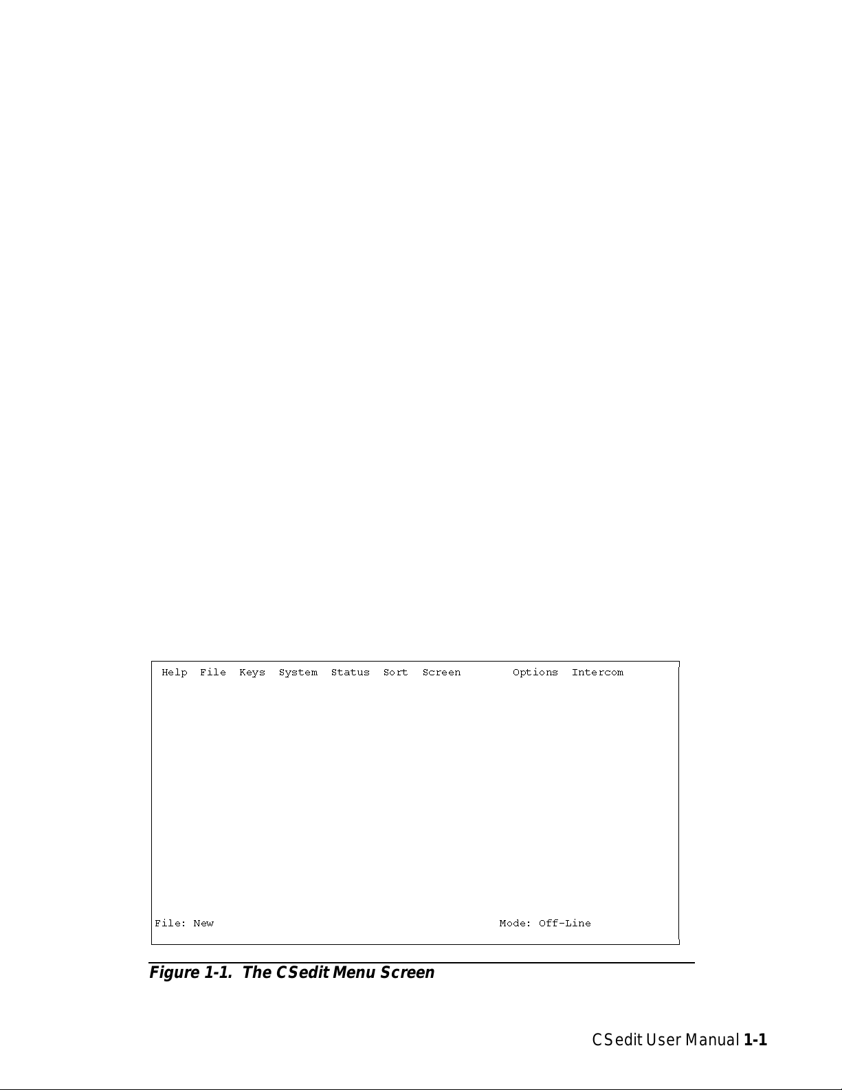
CSedit Start-up Routine
When CSedit is started, it will present the CSedit menu
screen (Figure 1-1). Next, it will check for a connection
to the intercom system. If it finds a connection, it will
upload the current system configuration from the intercom system. While CSedit is uploading the configuration,
it will report the percentage completed at the bottom of
the menu screen.
Note If you are using a laptop computer or other com-
puter with a monochrome display, you will have
to change the CSedit color mode for proper
screen display. See "Options Menu", page 3-5.
CSedit Menu Screen
The CSedit menu screen displays the menu bar across the
top of the screen. The menu bar lists all of the available
CSedit menus from which you will make selections. The
filename of the currently opened system configuration
file displays in the lower-left corner of the screen. The
mode (either on-line or off-line) displays in the lowerright corner of the screen.
Note If the computer is on-line with the intercom sys-
tem when CSedit is started, the on-line configuration file will automatically be opened for
editing in CSedit. If the computer is off-line, no
file will be opened, and the filename will be
“New”.
ÚÄÄÄÄÄÄÄÄÄÄÄÄÄÄÄÄÄÄÄÄÄÄÄÄÄÄÄÄÄÄÄÄÄÄÄÄÄÄÄÄÄÄÄÄÄÄÄÄÄÄÄÄÄÄÄÄÄÄÄÄÄÄÄÄÄÄÄÄÄÄÄÄÄÄÄÄÄÄÄÄ¿
³ Help File Keys System Status Sort Screen Options Intercom ³
³ ³
³ ³
³ ³
³ ³
³ ³
³ ³
³ ³
³ ³
³ ³
³ ³
³ ³
³ ³
³ ³
³ ³
³ ³
³ ³
³ ³
³ ³
³ ³
³ ³
³ ³
³ ³
³File: New Mode: Off-Line ³
³ ³
ÀÄÄÄÄÄÄÄÄÄÄÄÄÄÄÄÄÄÄÄÄÄÄÄÄÄÄÄÄÄÄÄÄÄÄÄÄÄÄÄÄÄÄÄÄÄÄÄÄÄÄÄÄÄÄÄÄÄÄÄÄÄÄÄÄÄÄÄÄÄÄÄÄÄÄÄÄÄÄÄÄÙ
Figure 1-1. The CSedit Menu Screen
CSedit User Manual 1-1
Page 7
Menu Selection Using the Computer
Keyboard
1. Use the LEFT and RIGHT cursor keys on the computer
keyboard (←→)to move the cursor from one menu
to another on the menu bar. The currently selected
menu will be highlighted.
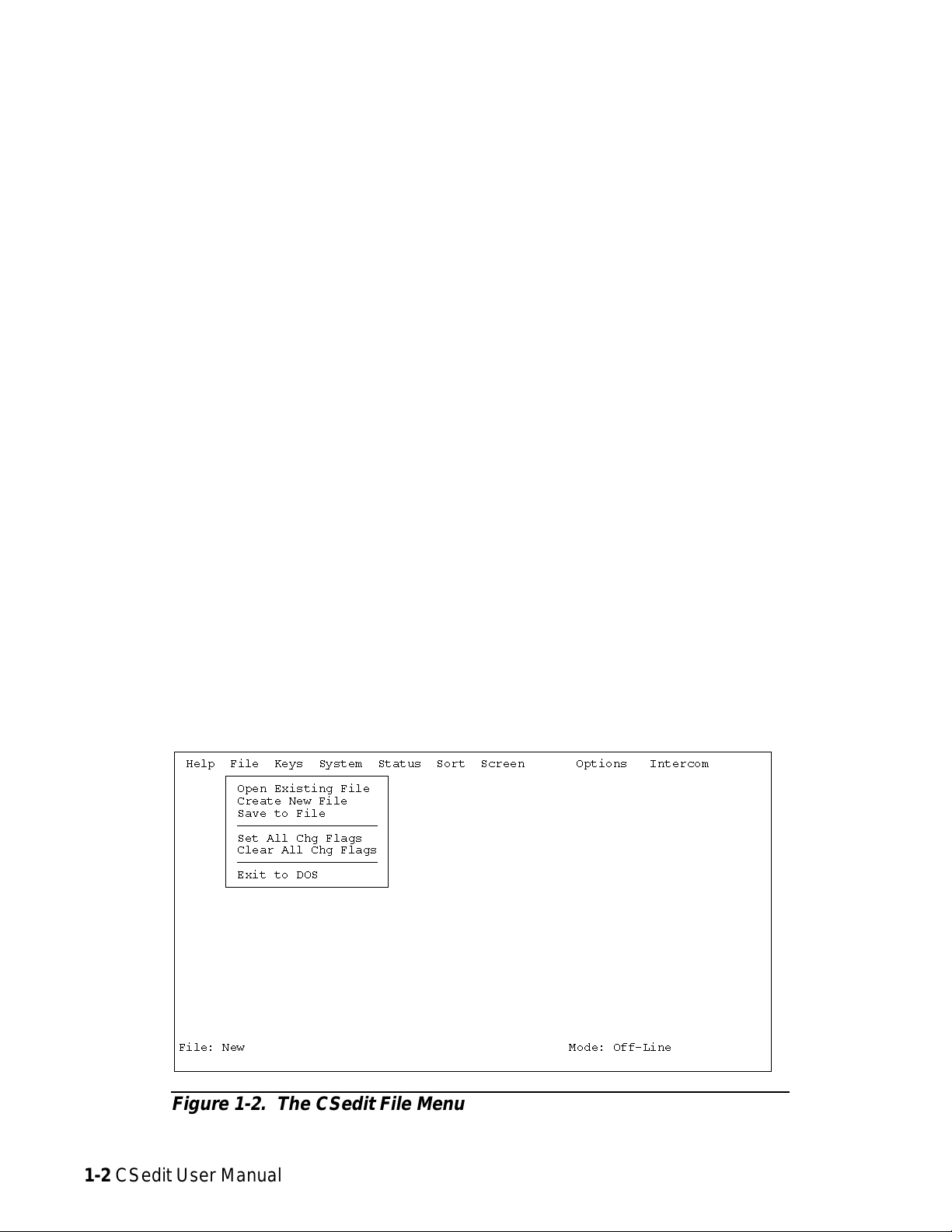
2. Press the ENTER key or DOWN cursor key (↓)to
open the selected menu. Figure 1-2 shows the
opened File menu.
3. Use the UP/DOWN cursor keys to highlight a menu
item, then press the ENTER key to select it.
4. Press the ESCAPE key to cancel a selection. Press
ESCAPE again to close a menu and return to the
menu bar.
Menu Selection Using a Mouse
You must install the mouse and its software prior to running CSedit. Follow the instructions that came with your
mouse. If there is a choice, install your mouse as a Microsoft® compatible mouse.
Note If your mouse does not work, the CSedit com port
settingsmaybeincorrect.See "Options, Communications", page3-6.
To use a mouse with CSedit:
1. From the CSedit menu bar, point and click the left
mouse button on a menu to open it.
2. Point and click the left mouse button on a menu item to
select that item.
The function keys also drop down menus:
F1 Help
F2 Files
F3 Keys
F4 System
F5 Status
F6 Sort
F7* Screen
F8 Not used
F9 Options
F10 Intercom
* This menu is accessible only during certain editing pro-
cedures.
ÚÄÄÄÄÄÄÄÄÄÄÄÄÄÄÄÄÄÄÄÄÄÄÄÄÄÄÄÄÄÄÄÄÄÄÄÄÄÄÄÄÄÄÄÄÄÄÄÄÄÄÄÄÄÄÄÄÄÄÄÄÄÄÄÄÄÄÄÄÄÄÄÄÄÄÄÄÄÄÄÄ¿
³ Help File Keys System Status Sort Screen Options Intercom ³
³ ÚÄÄÄÄÄÄÄÄÄÄÄÄÄÄÄÄÄÄÄÄÄ¿ ³
³ ³ Open Existing File ³ ³
³ ³ Create New File ³ ³
³ ³ Save to File ³ ³
³ ³ ÄÄÄÄÄÄÄÄÄÄÄÄÄÄÄÄÄÄÄ ³ ³
³ ³ Set All Chg Flags ³ ³
³ ³ Clear All Chg Flags ³ ³
³ ³ ÄÄÄÄÄÄÄÄÄÄÄÄÄÄÄÄÄÄÄ ³ ³
³ ³ Exit to DOS ³ ³
³ ÀÄÄÄÄÄÄÄÄÄÄÄÄÄÄÄÄÄÄÄÄÄÙ ³
³ ³
³ ³
³ ³
³ ³
³ ³
³ ³
³ ³
³ ³
³ ³
³ ³
³ ³
³ ³
³File: New Mode: Off-Line ³
³ ³
ÀÄÄÄÄÄÄÄÄÄÄÄÄÄÄÄÄÄÄÄÄÄÄÄÄÄÄÄÄÄÄÄÄÄÄÄÄÄÄÄÄÄÄÄÄÄÄÄÄÄÄÄÄÄÄÄÄÄÄÄÄÄÄÄÄÄÄÄÄÄÄÄÄÄÄÄÄÄÄÄÄÙ
3. To cancel a selection, click on any selectable item with
the right mouse button. To close a menu and return to
the menu bar, click on any menu item with the right
mouse button.
Figure 1-2. The CSedit File Menu
1-2 CSedit User Manual
Page 8
CSedit Editing Screens
Figure 1-3 shows a typical editing screen that opens after
a menu item is selected. This particular editing screen
will open when you select “ISOs” from the “System”
menu. The ISOs editing screen contains two windows.
The window at the left is an edit table to configure camera ISOs. This table has several columns in which you enter information to configure ISOs. The window at the
right side of the screen is a pick list. A pick list is simply
a list from which you can pick items to insert into edit tables as you configure the intercom system. Some pick
lists may open up into sub lists when you pick items.
ENTER Key: Enters information that you have typed
into a column, and moves the cursor to the next column
or down to the next line. Enters the currently selected
item in a pick list into the currently selected position in an
edit table in another window.
Plus “+” Key on Numeric Keypad: Inserts the currently
selected item in a pick list into the currently selected position in an edit table, and then advances the cursor to the
next row of the table. (Useful for speed formatting, see
"Speed Formatting", page 3-8.)
Movement in Editing Screens Using a
Mouse
Movement in Editing Screens Using the
Computer Keyboard
ESCAPE Key: Exits a sub list or menu item and returns
you to the previous screen.
TAB Key: Moves the cursor from one window to another. The border around the currently selected window
will be highlighted.
SHIFT+TAB Keys: Moves the cursor back into the previous window.
CURSOR Keys (↑↓→←): Move the cursor within the
current window. Some tables and pick lists may also have
scroll buttons (
use the UP/DOWN cursor keys (↑↓) to scroll the screen
and view additional items.
st
) like the ones shown in Figure 1-3;
ÚÄÄÄÄÄÄÄÄÄÄÄÄÄÄÄÄÄÄÄÄÄÄÄÄÄÄÄÄÄÄÄÄÄÄÄÄÄÄÄÄÄÄÄÄÄÄÄÄÄÄÄÄÄÄÄÄÄÄÄÄÄÄÄÄÄÄÄÄÄÄÄÄÄÄÄÄÄÄÄÄ¿
³ Help File Keys System Status Sort Screen Options Intercom ³
³ ÉÍÍÍÍÍÍÍÍÍÍÍÍÍÍÍÍÍÍÍÍÍÍÍÍÍÍÍÍÍÍÍÍÍÍÍÍÍÍÍÍÍÍÍÍÍÍÍÍÍÍ» ÉÍÍÍÍÍÍÍÍÍÍÍÍÍÍÍÍ» ³
³ º Camera Isolate Assignments º º Outputs º ³
³ ºÍÍÍÍÍÍÑÍÍÍÍÍÑÍÍÍÍÍÑÍÍÍÍÍÑÍÍÍÍÍÑÍÍÍÑÍÍÍÍÍÍÍÍÍÍÍÑÍÍͺ ºÍÍÍÍÍÍÑÍÍÍÍÍÑÍÍͺ ³
³ ºAlpha ³Alias³ ISO ³ Chg ³ AUC ³Slf³ Output ³ º ºAlpha ³Port ³ º ³
³ ºÄÄÄÄÄÄÅÄÄÄÄÄÅÄÄÄÄÄÅÄÄÄÄÄÅÄÄÄÄÄÅÄÄÄÅÄÄÄÄÄÄÄÄÄÄÄÅÄÄĺ ºÄÄÄÄÄÄÅÄÄÄÄÄÅÄÄĺ ³
³ º IS01 ³IS01 ³ 1 ³ ú ³ úûû ³ ú ³ ---- ³ º º N145 ³ 145 ³sº³
³ ºIS02³IS02³ 2³ ú ³úûû³ú³---- ³²º ºN146³146³°º ³
³ ºIS03³IS03³ 3³ ú ³úûû³ú³---- ³²º ºN147³147³°º ³
³ ºIS04³IS04³ 4³ ú ³úûû³ú³---- ³²º ºN148³148³°º ³
³ ºIS05³IS05³ 5³ ú ³úûû³ú³---- ³²º ºN149³149³°º ³
³ ºIS06³IS06³ 6³ ú ³úûû³ú³---- ³°º ºN150³150³°º ³
³ ºIS07³IS07³ 7³ ú ³úûû³ú³---- ³°º ºN151³151³²º ³
³ ºIS08³IS08³ 8³ ú ³úûû³ú³---- ³°º ºN152³152³°º ³
³ ºIS09³IS09³ 9³ ú ³úûû³ú³---- ³°º ºN153³153³°º ³
³ ºIS10³IS10³ 10³ ú ³úûû³ú³---- ³°º ºN154³154³°º ³
³ ºIS11³IS11³ 11³ ú ³úûû³ú³---- ³°º ºN155³155³°º ³
³ ºIS12³IS12³ 12³ ú ³úûû³ú³---- ³°º ºN156³156³°º ³
³ ºIS13³IS13³ 13³ ú ³úûû³ú³---- ³°º ºN157³157³°º ³
³ ºIS14³IS14³ 14³ ú ³úûû³ú³---- ³°º ºN158³158³°º ³
³ ºIS15³IS15³ 15³ ú ³úûû³ú³---- ³°º ºN159³159³°º ³
³ ºIS16³IS16³ 16³ ú ³úûû³ú³---- ³tº º N160 ³ 160 ³tº³
³ ÈÍÍÍÍÍÍÍÍÍÍÍÍÍÍÍÍÍÍÍÍÍÍÍÍÍÍÍÍÍÍÍÍÍÍÍÍÍÍÍÍÍÍÍÍÍÍÍÍÍͼ ÈÍÍÍÍÍÍÍÍÍÍÍÍÍÍÍͼ ³
³File: New Mode: Off-Line ³
³ ³
ÀÄÄÄÄÄÄÄÄÄÄÄÄÄÄÄÄÄÄÄÄÄÄÄÄÄÄÄÄÄÄÄÄÄÄÄÄÄÄÄÄÄÄÄÄÄÄÄÄÄÄÄÄÄÄÄÄÄÄÄÄÄÄÄÄÄÄÄÄÄÄÄÄÄÄÄÄÄÄÄÄÙ
Click on any item in an edit table to select the edit table.
Move the cursor over a pick list to select the pick list. The
border around the currently selected window will be highlighted. Clicking on an item in a pick list will insert that
item into the currently selected position in an edit table.
Using Help
F1 Key: Calls context-sensitive help from within CSedit.
Context sensitive means the help screens will provide information about the currently selected menu or menu item.
Key Words in Help Screens: Certain words may be highlighted in a help screen. Select these words with the
UP/DOWN/LEFT/RIGHT cursor keys, then press the ENTER key to get additional help. Or, if you are using a
mouse, click on the key word for additional help.
Figure 1-3. A Typical Editing Screen Showing an Edit Table at Left
and a Pick List at Right
CSedit User Manual 1-3
Page 9

Scrolling in Help Screens: Some help topics may take
more than one screen. In such cases, use the DOWN/UP
cursor keys to scroll down or up. If you scroll beyond the
end of the help topic, the cursor will automatically return
to the beginning of the topic.
BACK SPACE Key in a Help Screen: Returns you to
the previous help screen.
ESCAPE Key in Help: Returns you to CSedit.
Activating a New File or Sending
Changes
To send your changes to the intercom system, use one of
two options on the Intercom menu:
• Activate Chgs: Active only when you have modi-
fied the on-line file. This option sends all the
changes which have been made since the last time
the file was saved or sent to the intercom system.
Creating / Editing Configuration Files
If the computer is on-line with the intercom system when
CSedit is started, the on-line configuration file is automatically opened for editing. To create a new file or edit an
existing configuration other than the on-line configuration, select one of two options from the File menu:
• Open Existing File: This opens a configuration
file that is already on disk. If you have done any
editing before selecting this option, you will be
prompted to save your work or send it to the intercom before a new file is opened. You will also be
asked “What Would You Like To Do With
Change Flags”. See the Change Flag description,
at right.
• Create New File: This clears all settings and creates a blank intercom configuration. If you have
done any editing before selecting this option,
you will be prompted to save your work or send
it to the intercom before all settings are cleared.
You will also be asked “What Would You Like
To Do With Change Flags”. See the Change
Flag description, a t r ight.
If, after creating a new file or editing a file on disk, you
wish to make changes to the on-line intercom configuration file, select “Open On-Line” from the Intercom menu.
• Send File: Active only when CSedit is in communication with the intercom, but editing a file other
than the on-line file. This option sends only those
items that have change flags set. To send the entire contents of a file, first select “Set All Chg
Flags” from the File menu. See the Change Flag
description, below, for further information about
the use of change flags.
Quitting CSedit
To quit CSedit when you are finished editing, select Exit
to DOS from the File menu and then press the ENTER
key. If you have not saved your changes, CSedit will ask
you if you want to do this.
Change Flags
General Description
Each item that can be changed in CSedit has an associated change flag. These change flags display as check
marksûnext to the items that you change. The change
flags control which items are downloaded to the intercom
system when a file is sent. Only those items that have
change flags turned on (set) will be sent.
Editing a Configuration
Once you have selected one of the above file options, you
may edit the opened file using the editing procedures described in Section 2 of this manual.
Saving Changes
When you are finished creating a new configuration or editing an existing configuration, save your changes using
the “Save to File” option on the File menu.
1-4 CSedit User Manual
Change Flag Prompt when Opening or
Saving a File
Whenever you open a file or create a new file, you will
first see the prompt “What would you like to do with
Change Flags?”
Selecting “Set All Chg Flags” will turn on all change
flags in the file that you are currently editing. If you send
the file to the intercom system after selecting this option,
the current intercom system configuration will be completely overwritten by the new configuration.
Selecting “Leave Chg Flags” will leave all change flags
on that are currently on and will leave all change flags off
Page 10

that are currently off. Only those items that have
change flags set would be sent to the intercom system during a download, resulting in only a partial modification of
the current intercom system configuration.
Selecting “Clear All Chg Flags will turn off all change
flags in the file that you are currently editing. If you then
tried to send the file to the intercom system, it would have
no effect.
Uses of the Change Flags
c) Send your configuration to the intercom system us-
ing the “Send File” command in the Intercom
menu. Since all the change flags are set, the entire configuration file will be sent, and the current intercom system configuration will be
entirely overwritten. Your basic configuration is
now in place.
d) Prepare your first update file: Using the “Save to
File” command on the File menu, save your basic configuration to a new file with a new name.
Select “Clear All Chg Flags” when prompted.
Change flags can be used in three ways to create various
configuration changes:
1. If you are on-line with the intercom system and editing
the on-line configuration, change flags will automatically be set for any items that you change. Selecting
“Activate Chgs” from the Intercom menu will download all items with change flags set.
2. If you want to completely over-write the current intercom system configuration with a new configuration,
open the new configuration file, then select “Set All
Chg Flags”. This will assure that all items in the file
are sent. Now send the file using the “Send File”
command on the Intercom menu.
3. The “Send File” command on the Intercom menu can
also be used to make periodic updates to the intercom
system using files that you prepared previously. Only
the items that you wish to change will be sent, which
means that updating can proceed much more quickly
than if you send an entire configuration file. Here is
how periodic updating works:
a) Set up a basic, or starting, intercom system configu-
ration. You can base this file on a previously existing configuration file by selecting “Open
Existing File” from the File menu. Or, you can
make a completely new file by selecting “Create
New File” from the File menu. Whichever
method you use, just make sure that you select
“Set All Chg Flags” when prompted.
e) Go ahead and make any changes that you want to
put into effect during updating. As you make
your changes, the change flags for those items
will automatically be set.
f) Again, save your update file to disk, but select
“Leave Chg Flags” when prompted.
g) Prepare any additional update files that you need
by saving the PREVIOUS UPDATE FILE with
a new name. As before, select “Clear All Chg
Flags” before you start editing the new file, and
select “Leave All Chg Flags” when you save or
re-open the file.
h) To send your first update, open the desired update
file. Always select “Leave Chg Flags” when
opening your update files. Then select “Send
File” from the Intercom menu. Only those items
that have change flags set will be sent.
i) Continue to make periodic updates as needed by
sending new update files. To return to your basic
configuration at any time, simply send your basic configuration file to the intercom system.
Just remember when opening your basic configuration or any update files, always select “Leave
Chg Flags”.
b) Go ahead and configure the intercom system as
you want it to operate at the start. When your
starting configuration is completed, save it to
file. Again, select “Set All Chg Flags” when
prompted (in case you inadvertently turned off
any change flags while editing).
CSedit User Manual 1-5
Page 11

This page intentionally left blank.
1-6 CSedit User Manual
Page 12

Section 2: Editing Procedures
Assigning Names (Alphas & Aliases)
Introduction
The following editing procedures are arranged in the general order that you would typically use them when creating a new intercom system configuration.
General Procedure to Configure the
Intercom System
1. Assign names for individual ports (channels) of the intercom system. (Page 2-1.)
2. Configure and name any party lines, IFBs etc. that will be
needed. (Pages 2-3 through 2-14.)
3. Assign keys on keypanels to talk and/or listen to ports,
party lines etc. (Pages 2-15 through 2-21.)
Additional Requirements for Trunked
Intercoms
If the intercom system is interconnected (trunked) to
other intercom systems, three additional steps are also required:
General Description
CSedit lets you assign 4-character, alpha-numeric names
to individual ports for point-to-point communication. It
also lets you assign names to other types of communication such as party lines, IFB’s and so forth. These names
will appear in keypanel alpha-numeric displays when the
ports, party lines etc. are assigned to keys. (Even if your
system does not use alpha-numeric keypanels, naming users will make it easier to change the intercom system configuration in the future.)
Two names are assigned for each port, party line, etc. The
first name is the “Alpha” name. This name is used within
the local intercom system, that is, the intercom system
where the port, party line etc. is located. The second
name is the “Alias” name. If the local intercom system is
interconnected (trunked) with other intercom systems, the
Alias name will appear in keypanel displays in the other
intercom systems. By default, when you create an Alpha
name, the Alias name is automatically made the same.
However, if that name is already used in the other intercom system, the Alias name can be changed to prevent
mix-ups.
Important!
1. Reserve one or more intercom ports for use as communication channels between the intercom systems. See
"Restricting a Port for Use As a Trunking Port", page
2-21 .
2. Remove restrictions from any ports, party lines, etc. in
one intercom system that you want to make available
for key assignment in other intercom systems. (By default, all devices in one intercom system are restricted from being assigned in other intercom
systems.) Applying and removing restrictions is discussed in the separate setup procedures for ports,
party lines, etc. on the following pages.
3. Run the companion program, CStrunk, to configure the
trunking ports for communication between intercom
systems. Once the trunk lines are up and running,
keypanel keys may be assigned in each trunked intercom system to access ports, party lines etc. in other
intercom systems.
Every name assigned in CSedit should be unique. Unless
you are an advanced user of CSedit, avoid using a name
for one type of communication (port, party line, etc.) that
has already been assigned to some other type of communication, as this could cause unpredictable results.
Naming Individual Audio Ports
1. From the menu bar, select the System menu, then select
“Port Alphas”. The Port Alpha Assignments screen
should appear (Figure 2-1).
CSedit User Manual 2-1
Page 13
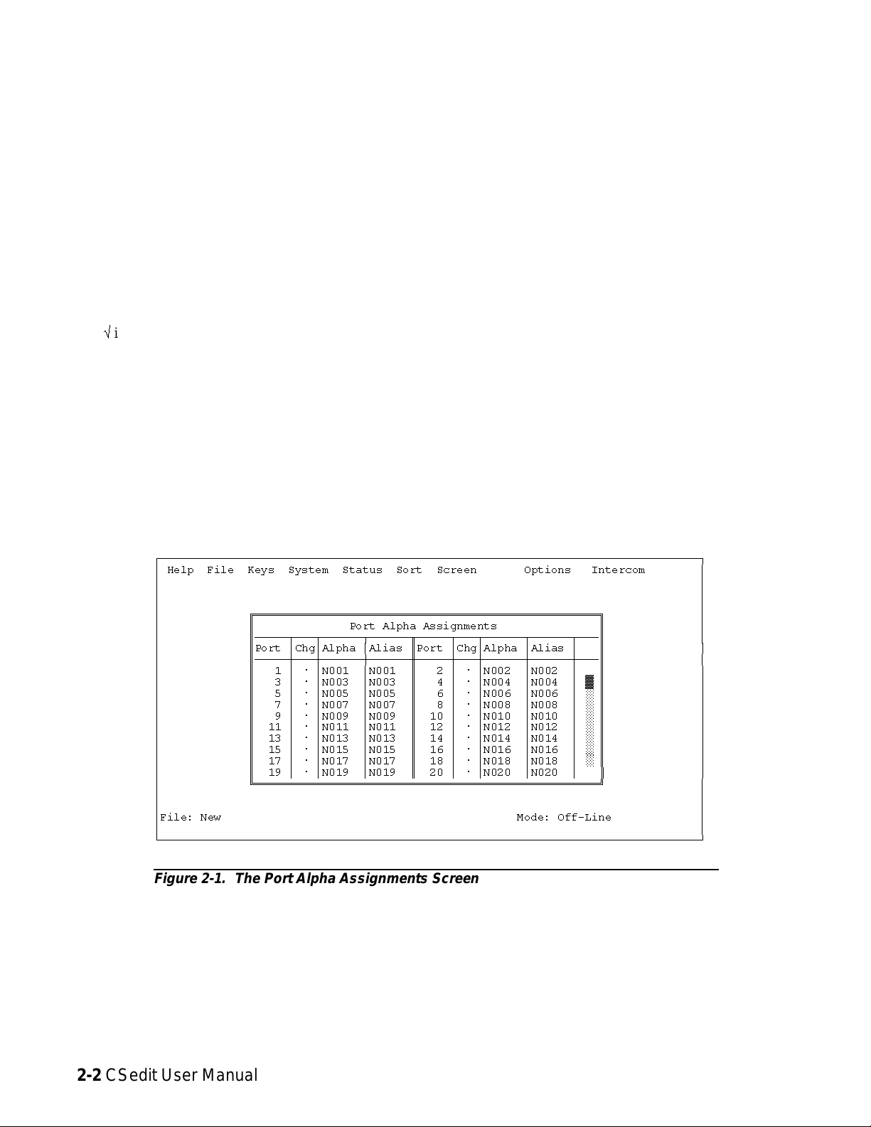
2. Each intercom audio port has a Port number (1, 2, 3
etc.). Port numbers cannot be changed, since they are
the physical points where intercom stations are connected to the intercom system. Alongside each Port
number are columns for entering Alpha and Alias
names. You may enter names using any combination
of up to four characters. To change an Alpha or
Alias, select it (using the cursor keys or by moving
the mouse cursor over it) and then type in a new
name. Press the ENTER key to record the new name
and move to the next column (or simply move the
mouse cursor).
When you make a change to an Alpha or Alias and move
to a new position, you will notice that a check mark
û
is inserted in the "Chg" column next to the Port
number. This check mark is a change flag. (See the
change flag description on page 1-4 for further details.)
Note When assigning Alphas for personnel located in
the same area, we suggest using the same first
character in each Alpha. For example, if you
have 2 control rooms, you might use 1-TD,
1DIR, 1-AO, 2-TD, 2DIR, 2-AO etc. This will
cause the names of personnel in the same area to
be grouped together in pick lists for easier key
assignment. It may also make it easier for keypanel operators to identify related personnel on
their keypanels.
3. Press the ESCAPE key (or click the right mouse button
on any selectable item) to return to the CSedit menu
screen when finished naming ports.
4. Remember to save your changes and send them to the
intercom system when finished. (See "Activating a
New File or Sending Changes", page 1-4.)
Naming Other Types of Communication
(Party Lines, ISO’s etc.)
Other types of communication are named as they are configured. See "Creating a Party Line", "Creating an IFB"
etc., on the following pages.
ÚÄÄÄÄÄÄÄÄÄÄÄÄÄÄÄÄÄÄÄÄÄÄÄÄÄÄÄÄÄÄÄÄÄÄÄÄÄÄÄÄÄÄÄÄÄÄÄÄÄÄÄÄÄÄÄÄÄÄÄÄÄÄÄÄÄÄÄÄÄÄÄÄÄÄÄÄÄÄÄÄ¿
³ Help File Keys System Status Sort Screen Options Intercom ³
³ ³
³ ³
³ ³
³ ÉÍÍÍÍÍÍÍÍÍÍÍÍÍÍÍÍÍÍÍÍÍÍÍÍÍÍÍÍÍÍÍÍÍÍÍÍÍÍÍÍÍÍÍÍÍÍÍÍÍÍÍ» ³
³ º Port Alpha Assignments º ³
³ ºÄÄÄÄÄÂÄÄÄÂÄÄÄÄÄÄÂÄÄÄÄÄÄÒÄÄÄÄÄÂÄÄÄÂÄÄÄÄÄÄÂÄÄÄÄÄÄÂÄÄĺ ³
³ ºPort ³Chg³Alpha ³Alias ºPort ³Chg³Alpha ³Alias ³ º ³
³ ºÄÄÄÄÄÅÄÄÄÅÄÄÄÄÄÄÅÄÄÄÄÄÄ×ÄÄÄÄÄÅÄÄÄÅÄÄÄÄÄÄÅÄÄÄÄÄÄÅÄÄĺ ³
³ º 1 ³ ú ³N001 ³N001 º 2 ³ ú ³N002 ³N002 ³ º ³
³ º 3 ³ ú ³N003 ³N003 º 4 ³ ú ³N004 ³N004 ³ ² º ³
³ º 5 ³ ú ³N005 ³N005 º 6 ³ ú ³N006 ³N006 ³ ° º ³
³ º 7 ³ ú ³N007 ³N007 º 8 ³ ú ³N008 ³N008 ³ ° º ³
³ º 9 ³ ú ³N009 ³N009 º 10 ³ ú ³N010 ³N010 ³ ° º ³
³ º 11 ³ ú ³N011 ³N011 º 12 ³ ú ³N012 ³N012 ³ ° º ³
³ º 13 ³ ú ³N013 ³N013 º 14 ³ ú ³N014 ³N014 ³ ° º ³
³ º 15 ³ ú ³N015 ³N015 º 16 ³ ú ³N016 ³N016 ³ ° º ³
³ º 17 ³ ú ³N017 ³N017 º 18 ³ ú ³N018 ³N018 ³ ° º ³
³ º 19 ³ ú ³N019 ³N019 º 20 ³ ú ³N020 ³N020 ³▼º³
³ ÈÍÍÍÍÍÍÍÍÍÍÍÍÍÍÍÍÍÍÍÍÍÍÍÍÍÍÍÍÍÍÍÍÍÍÍÍÍÍÍÍÍÍÍÍÍÍÍÍÍÍͼ ³
³ ³
³ ³
³File: New Mode: Off-Line ³
³ ³
ÀÄÄÄÄÄÄÄÄÄÄÄÄÄÄÄÄÄÄÄÄÄÄÄÄÄÄÄÄÄÄÄÄÄÄÄÄÄÄÄÄÄÄÄÄÄÄÄÄÄÄÄÄÄÄÄÄÄÄÄÄÄÄÄÄÄÄÄÄÄÄÄÄÄÄÄÄÄÄÄÄÙ
Figure 2-1. The Port Alpha Assignments Screen
2-2 CSedit User Manual
Page 14
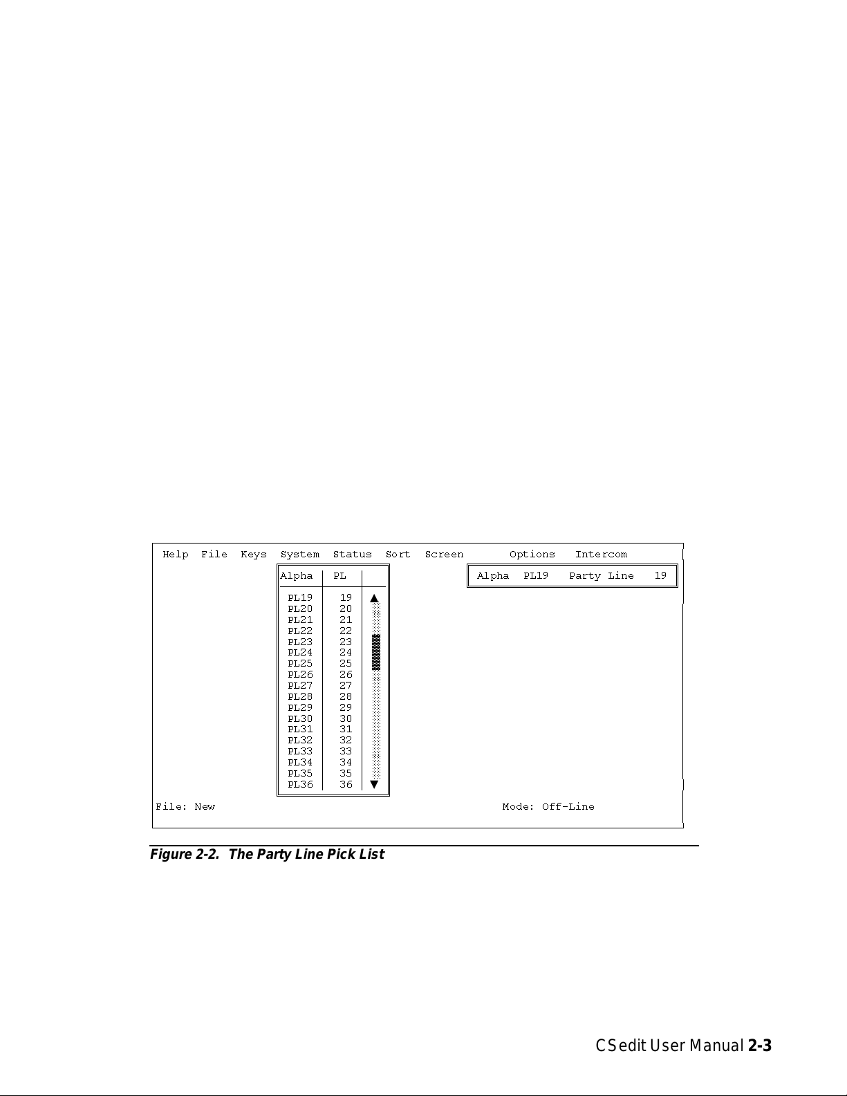
Creating a Party Line
To set up a party line:
A party line is a group of intercom stations that can always talk and/or listen to each other.
Note Usually, keypanels should not be assigned as per-
manent members of a party line (although this
can be done if desired). Instead, keypanel keys
are usually programmed to talk and listen to
party lines as needed. See "Keypanel Setup",
starting on page 2-15, for information on how to
assign keys.
1. From the menu bar, select the System menu, then select
“Party Lines”. The party line pick list should appear
(Figure 2-2). The default Alpha names for party lines
are PL01, PL02 etc. As you configure party lines you
can change the Alphas to more meaningful names for
your intercom system.
2. To select a party line for configuring, highlight it with
the cursor, then press the ENTER key (or click on a
party line with a mouse). The editing screen for the
selected party line should appear (Figure 2-3).
ÚÄÄÄÄÄÄÄÄÄÄÄÄÄÄÄÄÄÄÄÄÄÄÄÄÄÄÄÄÄÄÄÄÄÄÄÄÄÄÄÄÄÄÄÄÄÄÄÄÄÄÄÄÄÄÄÄÄÄÄÄÄÄÄÄÄÄÄÄÄÄÄÄÄÄÄÄÄÄÄÄ¿
³ Help File Keys System Status Sort Screen Options Intercom ³
³ ÉÍÍÍÍÍÍÍÍÍÍÍÍÍÍÍÍ» ÉÍÍÍÍÍÍÍÍÍÍÍÍÍÍÍÍÍÍÍÍÍÍÍÍÍÍÍÍÍÍÍ»³
³ ºAlpha ³ PL ³ º º Alpha PL19 Party Line 19 º³
³ ºÄÄÄÄÄÄÅÄÄÄÄÄÅÄÄĺ ÈÍÍÍÍÍÍÍÍÍÍÍÍÍÍÍÍÍÍÍÍÍÍÍÍÍÍÍÍÍÍͼ³
³ º PL19 ³ 19 ³▲º³
³ º PL20 ³ 20 ³ ° º ³
³ º PL21 ³ 21 ³ ° º ³
³ º PL22 ³ 22 ³ ° º ³
³ º PL23 ³ 23 ³ ² º ³
³ º PL24 ³ 24 ³ ² º ³
³ º PL25 ³ 25 ³ ² º ³
³ º PL26 ³ 26 ³ ° º ³
³ º PL27 ³ 27 ³ ° º ³
³ º PL28 ³ 28 ³ ° º ³
³ º PL29 ³ 29 ³ ° º ³
³ º PL30 ³ 30 ³ ° º ³
³ º PL31 ³ 31 ³ ° º ³
³ º PL32 ³ 32 ³ ° º ³
³ º PL33 ³ 33 ³ ° º ³
³ º PL34 ³ 34 ³ ° º ³
³ º PL35 ³ 35 ³ ° º ³
³ º PL36 ³ 36 ³▼º³
³ ÈÍÍÍÍÍÍÍÍÍÍÍÍÍÍÍͼ ³
³File: New Mode: Off-Line ³
³ ³
ÀÄÄÄÄÄÄÄÄÄÄÄÄÄÄÄÄÄÄÄÄÄÄÄÄÄÄÄÄÄÄÄÄÄÄÄÄÄÄÄÄÄÄÄÄÄÄÄÄÄÄÄÄÄÄÄÄÄÄÄÄÄÄÄÄÄÄÄÄÄÄÄÄÄÄÄÄÄÄÄÄÙ
Figure 2-2. The Party Line Pick List
CSedit User Manual 2-3
Page 15
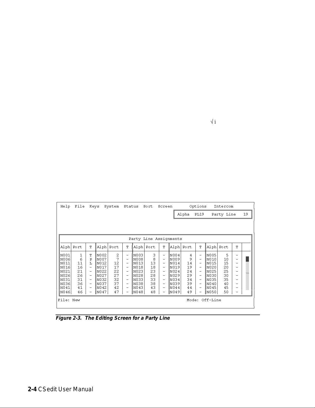
Figure 2-3 shows the editing screen for party line, PL19.
The Party Line Assignments table at the bottom of the
screen is used to assign intercom ports to the party line.
The window in the upper-right corner of the screen pops
open when selected to name the party line and restrict access for key assignment.
3. To assign an intercom port to the party line, move to the
“T” column next to the port. Then, use the SPACE
BAR, or click with a mouse, to select “P”, “T”, “L”
or “-”:
• Selecting “P” will let the port talk and listen on
the party line
• Selecting “T” will let the port talk only
• Selecting “L” will let the port listen only
• Selecting “-” will disconnect the port from the
party line
4. To name the party line or restrict party line usage,
TAB to the upper-right window and press the ENTER key (or click on any selectable item in the upper-right window with the left b utton of a mouse).
The name/restriction editor screen should appear
(Figure 2-4).
5. In the sample screen shown in Figure 2-4, the default
Alpha is “PL19". This may be changed to any meaningful four-character name. When you type in a new
Alpha and move the cursor to a different position,
you will notice that the Alias is automatically
changed to the same name as the Alpha. If your intercom system is interconnected (trunked) with other intercom systems, the Alias name will appear in pick
lists, keypanel displays and so forth in the other intercom systems. If desired, you may enter a different
Alias name that will be more meaningful to personnel in the other intercom systems.
Note When you make any change to a party line and
move to a new position, you will notice that a
check markûis inserted next to “Data Changed”
in the name/restriction editor window. This
check mark is a change flag. (See the change
flag description on page 1-4 for further details.)
ÚÄÄÄÄÄÄÄÄÄÄÄÄÄÄÄÄÄÄÄÄÄÄÄÄÄÄÄÄÄÄÄÄÄÄÄÄÄÄÄÄÄÄÄÄÄÄÄÄÄÄÄÄÄÄÄÄÄÄÄÄÄÄÄÄÄÄÄÄÄÄÄÄÄÄÄÄÄÄÄÄ¿
³ Help File Keys System Status Sort Screen Options Intercom ³
³ ÉÍÍÍÍÍÍÍÍÍÍÍÍÍÍÍÍÍÍÍÍÍÍÍÍÍÍÍÍÍÍÍ»³
³ º Alpha PL19 Party Line 19 º³
³ ÈÍÍÍÍÍÍÍÍÍÍÍÍÍÍÍÍÍÍÍÍÍÍÍÍÍÍÍÍÍÍͼ³
³ ³
³ ³
³ ³
³ÉÍÍÍÍÍÍÍÍÍÍÍÍÍÍÍÍÍÍÍÍÍÍÍÍÍÍÍÍÍÍÍÍÍÍÍÍÍÍÍÍÍÍÍÍÍÍÍÍÍÍÍÍÍÍÍÍÍÍÍÍÍÍÍÍÍÍÍÍÍÍÍÍÍÍÍÍÍÍ»³
³º Party Line Assignments º³
³ºÄÄÄÄÂÄÄÄÄÄÂÄÄÄÒÄÄÄÄÂÄÄÄÄÄÂÄÄÄÒÄÄÄÄÂÄÄÄÄÄÂÄÄÄÒÄÄÄÄÂÄÄÄÄÄÂÄÄÄÒÄÄÄÄÂÄÄÄÄÄÂÄÄÄÂÄÄĺ³
³ºAlph³Port ³ T ºAlph³Port ³ T ºAlph³Port ³ T ºAlph³Port ³ T ºAlph³Port ³ T ³ º³
³ºÄÄÄÄÅÄÄÄÄÄÅÄÄÄ×ÄÄÄÄÅÄÄÄÄÄÅÄÄÄ×ÄÄÄÄÅÄÄÄÄÄÅÄÄÄ×ÄÄÄÄÅÄÄÄÄÄÅÄÄÄ×ÄÄÄÄÅÄÄÄÄÄÅÄÄÄÅÄÄĺ³
³ºN001³ 1³TºN002³ 2³-ºN003³ 3³-ºN004³ 4³-ºN005³ 5³-³ º³
³ºN006³ 6³PºN007³ 7³-ºN008³ 8³-ºN009³ 9³-ºN010³ 10³-³²º³
³ºN011³ 11 ³ L ºN012³ 12 ³ - ºN013³ 13 ³ - ºN014³ 14 ³ - ºN015³ 15 ³ - ³ ° º³
³ºN016³ 16 ³ - ºN017³ 17 ³ - ºN018³ 18 ³ - ºN019³ 19 ³ - ºN020³ 20 ³ - ³ ° º³
³ºN021³ 21 ³ - ºN022³ 22 ³ - ºN023³ 23 ³ - ºN024³ 24 ³ - ºN025³ 25 ³ - ³ ° º³
³ºN026³ 26 ³ - ºN027³ 27 ³ - ºN028³ 28 ³ - ºN029³ 29 ³ - ºN030³ 30 ³ - ³ ° º³
³ºN031³ 31 ³ - ºN032³ 32 ³ - ºN033³ 33 ³ - ºN034³ 34 ³ - ºN035³ 35 ³ - ³ ° º³
³ºN036³ 36 ³ - ºN037³ 37 ³ - ºN038³ 38 ³ - ºN039³ 39 ³ - ºN040³ 40 ³ - ³ ° º³
³ºN041³ 41 ³ - ºN042³ 42 ³ - ºN043³ 43 ³ - ºN044³ 44 ³ - ºN045³ 45 ³ - ³ ° º³
³ºN046³ 46 ³ - ºN047³ 47 ³ - ºN048³ 48 ³ - ºN049³ 49 ³ - ºN050³ 50 ³ - ³▼º³
³ÈÍÍÍÍÍÍÍÍÍÍÍÍÍÍÍÍÍÍÍÍÍÍÍÍÍÍÍÍÍÍÍÍÍÍÍÍÍÍÍÍÍÍÍÍÍÍÍÍÍÍÍÍÍÍÍÍÍÍÍÍÍÍÍÍÍÍÍÍÍÍÍÍÍÍÍÍÍͼ³
³File: New Mode: Off-Line ³
³ ³
ÀÄÄÄÄÄÄÄÄÄÄÄÄÄÄÄÄÄÄÄÄÄÄÄÄÄÄÄÄÄÄÄÄÄÄÄÄÄÄÄÄÄÄÄÄÄÄÄÄÄÄÄÄÄÄÄÄÄÄÄÄÄÄÄÄÄÄÄÄÄÄÄÄÄÄÄÄÄÄÄÄÙ
Figure 2-3. The Editing Screen for a Party Line
2-4 CSedit User Manual
Page 16
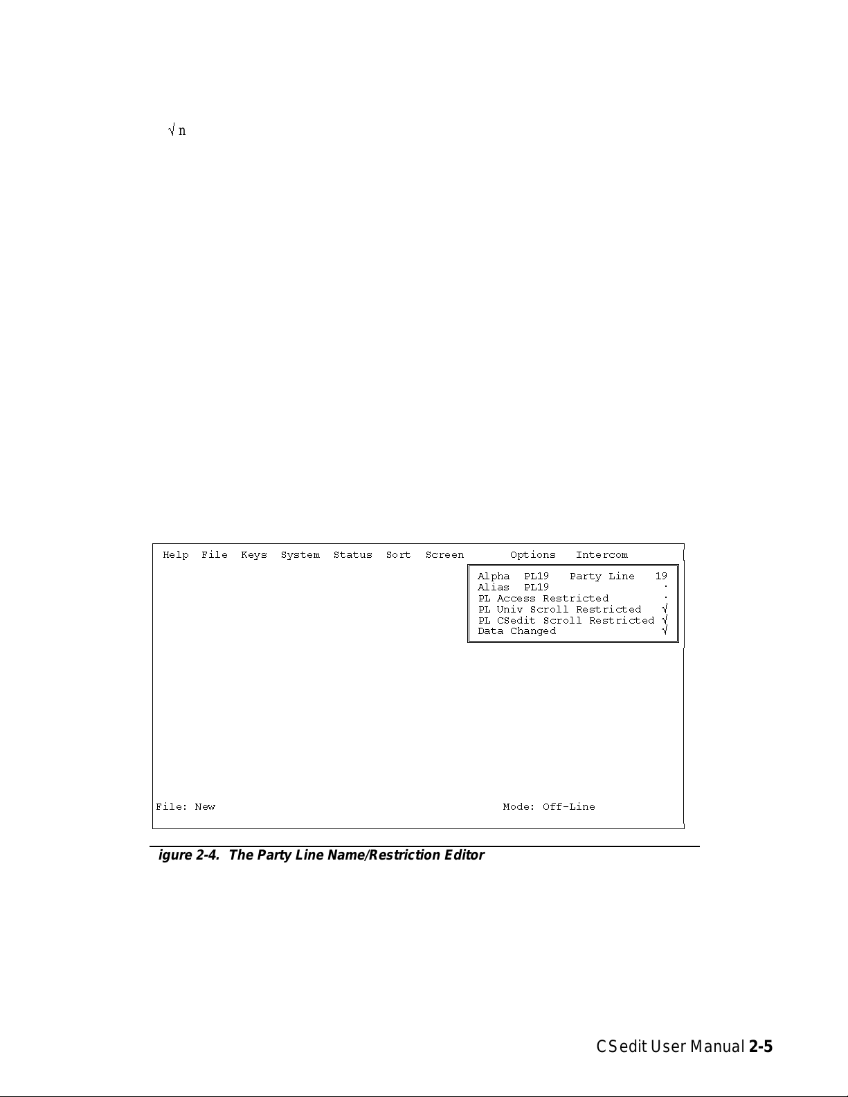
6. To apply or remove restrictions, use the cursor keys or
the mouse to select the desired restriction, then use
the SPACE BAR or click with the mouse to place a
check markûnext to the restriction:
• PL Access Restricted: A check mark here pre-
vents keypanel operators in the local intercom system from assigning this party line to keys from
their keypanels.
• PL Univ Scroll Restricted: If your intercom sys-
tem is trunked with other intercom systems, a
check mark here prevents keypanel operators in
other intercom systems from assigning this party
line to keys from their keypanels.
• PL CSedit Scroll Restricted: If your intercom sys-
tem is trunked, a check mark here prevents CSedit
users in other intercom systems from assigning
this party line in their intercom systems.
7. Press ESCAPE (or click on any selectable item with the
right mouse button) to return to the party line pick
list when finished configuring a party line. Press the
ESCAPE key again to return to the CSedit menu
screen when finished configuring party lines.
8. Remember to save your changes and send them to the
intercom system when finished. (See "Activating a
New File or Sending Changes", page 1-4.)
ÚÄÄÄÄÄÄÄÄÄÄÄÄÄÄÄÄÄÄÄÄÄÄÄÄÄÄÄÄÄÄÄÄÄÄÄÄÄÄÄÄÄÄÄÄÄÄÄÄÄÄÄÄÄÄÄÄÄÄÄÄÄÄÄÄÄÄÄÄÄÄÄÄÄÄÄÄÄÄÄÄ¿
³ Help File Keys System Status Sort Screen Options Intercom ³
³ ÉÍÍÍÍÍÍÍÍÍÍÍÍÍÍÍÍÍÍÍÍÍÍÍÍÍÍÍÍÍÍÍ»³
³ º Alpha PL19 Party Line 19 º³
³ º Alias PL19 ú º³
³ º PL Access Restricted ú º³
³ º PL Univ Scroll Restricted û º³
³ º PL CSedit Scroll Restricted û º³
³ º Data Changed û º³
³ ÈÍÍÍÍÍÍÍÍÍÍÍÍÍÍÍÍÍÍÍÍÍÍÍÍÍÍÍÍÍÍͼ³
³ ³
³ ³
³ ³
³ ³
³ ³
³ ³
³ ³
³ ³
³ ³
³ ³
³ ³
³ ³
³ ³
³ ³
³File: New Mode: Off-Line ³
³ ³
ÀÄÄÄÄÄÄÄÄÄÄÄÄÄÄÄÄÄÄÄÄÄÄÄÄÄÄÄÄÄÄÄÄÄÄÄÄÄÄÄÄÄÄÄÄÄÄÄÄÄÄÄÄÄÄÄÄÄÄÄÄÄÄÄÄÄÄÄÄÄÄÄÄÄÄÄÄÄÄÄÄÙ
Figure 2-4. The Party Line Name/Restriction Editor
CSedit User Manual 2-5
Page 17
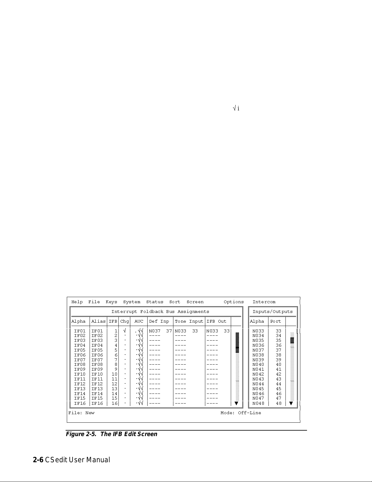
Creating an IFB ( Interrupt
Foldback Bus)
An IFB is a special use of an output port. The person connected to the output port usually hears a program source
connected to some input port of the intercom system. This
program source is then interrupted when a keypanel operator presses a key to talk to the person. The following procedure lets you define which output port you want to use for
IFB output, and which port will be used for program input.
You can also assign a meaningful name for the IFB. Once
you have configured an IFB, you can assign it to any keypanel key as described starting on page 2-15.
To set up an IFB:
1. From the menu bar, select the System menu, then select
“IFB Buses”. The IFB editing screen should appear
(Figure 2-5). Interrupt Foldback Bus Assignments
are shown in the table at the left of the screen. An Inputs/Outputs pick list is shown at the right. The default Alpha names for IFBs are IF01, IF02 etc. As
you configure IFBs you will also change the Alphas
to more meaningful names for your intercom system.
The number of available IFBs will vary depending
on the size of your intercom system.
2. Name the IFB: Use the UP/DOWN cursor keys to select
an IFB Alpha (or click on the desired Alpha with a
mouse). Then, enter a four-digit name for the IFB.
(The IFB Alpha may be the same as the output port
Alpha of the person that will be interrupted during
IFB operation. Just remember that assigning the port
to a talk key will have a different effect than assign-
ing the IFB to a talk key.) When you move the cursor
to a different position, you will notice that the Alias
changes to the same name as the Alpha*. If your intercom system is interconnected (trunked) with another intercom system you may enter a different
Alias name that will be meaningful to personnel in
the other intercom system.
Note When you make any change to an IFB and move
to a new position, you will notice that a check
markûis inserted in the “Chg” column. This
check mark is a change flag. (See the change
flag description on page 1-4 for further details.)
3. Specify the output port of the person to be interrupted
during IFB: Move to the “IFB Out” column. Type
the Alpha of the output port, or select it from the pick
list at the right side of the screen. In the example in
Figure 2-5, port N033 has been entered as the IFB
output for IF01.
Note To use the pick list to insert ports into the Inter-
rupt Foldback Bus Assignments table: Position
the cursor in the table at the point where you
want to make the insertion. Then, press the TAB
key to move the cursor into the Inputs/Outputs
pick list (or move the mouse cursor over the pick
list). Select a port from the pick list and press
ENTER (or click on a port with the left mouse
button). The selected port should appear in the
Interrupt Foldback Bus Assignments table.
* Except when an Alias has already been entered that is
different from the Alpha. In this case, the Alias will
not change whenever the Alpha is changed.
ÚÄÄÄÄÄÄÄÄÄÄÄÄÄÄÄÄÄÄÄÄÄÄÄÄÄÄÄÄÄÄÄÄÄÄÄÄÄÄÄÄÄÄÄÄÄÄÄÄÄÄÄÄÄÄÄÄÄÄÄÄÄÄÄÄÄÄÄÄÄÄÄÄÄÄÄÄÄÄÄÄ¿
³ Help File Keys System Status Sort Screen Options Intercom ³
³ÉÍÍÍÍÍÍÍÍÍÍÍÍÍÍÍÍÍÍÍÍÍÍÍÍÍÍÍÍÍÍÍÍÍÍÍÍÍÍÍÍÍÍÍÍÍÍÍÍÍÍÍÍÍÍÍÍÍÍÍ» ÉÍÍÍÍÍÍÍÍÍÍÍÍÍÍÍÍ»³
³º Interrupt Foldback Bus Assignments º º Inputs/Outputs º³
³ºÍÍÍÍÍÍÑÍÍÍÍÍÑÍÍÍÑÍÍÍÑÍÍÍÍÍÑÍÍÍÍÍÍÍÍÑÍÍÍÍÍÍÍÍÍÍÑÍÍÍÍÍÍÍÍÑÍÍͺ ºÍÍÍÍÍÍÑÍÍÍÍÍÑÍÍͺ³
³ºAlpha ³Alias³IFB³Chg³ AUC ³Def Inp ³Tone Input³IFB Out ³ º ºAlpha ³Port ³ º³
³ºÄÄÄÄÄÄÅÄÄÄÄÄÅÄÄÄÅÄÄÄÅÄÄÄÄÄÅÄÄÄÄÄÄÄÄÅÄÄÄÄÄÄÄÄÄÄÅÄÄÄÄÄÄÄÄÅÄÄĺ ºÄÄÄÄÄÄÅÄÄÄÄÄÅÄÄĺ³
³º IF01 ³IF01 ³ 1³ û ³ .ûû ³N037 37³N033 33 ³N033 33³ º º N033 ³ 33 ³▲º³
³º IF02 ³IF02 ³ 2³ ú ³ úûû ³---- ³---- ³---- ³ ² º º N034 ³ 34 ³ ° º³
³º IF03 ³IF03 ³ 3³ ú ³ úûû ³---- ³---- ³---- ³ ² º º N035 ³ 35 ³ ² º³
³º IF04 ³IF04 ³ 4³ ú ³ úûû ³---- ³---- ³---- ³ ² º º N036 ³ 36 ³ ° º³
³º IF05 ³IF05 ³ 5³ ú ³ úûû ³---- ³---- ³---- ³ ² º º N037 ³ 37 ³ ° º³
³º IF06 ³IF06 ³ 6³ ú ³ úûû ³---- ³---- ³---- ³ ° º º N038 ³ 38 ³ ° º³
³º IF07 ³IF07 ³ 7³ ú ³ úûû ³---- ³---- ³---- ³ ° º º N039 ³ 39 ³ ° º³
³º IF08 ³IF08 ³ 8³ ú ³ úûû ³---- ³---- ³---- ³ ° º º N040 ³ 40 ³ ° º³
³º IF09 ³IF09 ³ 9³ ú ³ úûû ³---- ³---- ³---- ³ ° º º N041 ³ 41 ³ ° º³
³º IF10 ³IF10 ³ 10³ ú ³ úûû ³---- ³---- ³---- ³ ° º º N042 ³ 42 ³ ° º³
³º IF11 ³IF11 ³ 11³ ú ³ úûû ³---- ³---- ³---- ³ ° º º N043 ³ 43 ³ ° º³
³º IF12 ³IF12 ³ 12³ ú ³ úûû ³---- ³---- ³---- ³ ° º º N044 ³ 44 ³ ° º³
³º IF13 ³IF13 ³ 13³ ú ³ úûû ³---- ³---- ³---- ³ ° º º N045 ³ 45 ³ ° º³
³º IF14 ³IF14 ³ 14³ ú ³ úûû ³---- ³---- ³---- ³ ° º º N046 ³ 46 ³ ° º³
³º IF15 ³IF15 ³ 15³ ú ³ úûû ³---- ³---- ³---- ³ ° º º N047 ³ 47 ³ ° º³
³º IF16 ³IF16 ³ 16³ ú ³ úûû ³---- ³---- ³---- ³▼º º N048 ³ 48 ³▼º³
³ÈÍÍÍÍÍÍÍÍÍÍÍÍÍÍÍÍÍÍÍÍÍÍÍÍÍÍÍÍÍÍÍÍÍÍÍÍÍÍÍÍÍÍÍÍÍÍÍÍÍÍÍÍÍÍÍÍÍÍͼ ÈÍÍÍÍÍÍÍÍÍÍÍÍÍÍÍͼ³
³File: New Mode: Off-Line ³
³ ³
ÀÄÄÄÄÄÄÄÄÄÄÄÄÄÄÄÄÄÄÄÄÄÄÄÄÄÄÄÄÄÄÄÄÄÄÄÄÄÄÄÄÄÄÄÄÄÄÄÄÄÄÄÄÄÄÄÄÄÄÄÄÄÄÄÄÄÄÄÄÄÄÄÄÄÄÄÄÄÄÄÄÙ
Figure 2-5. The IFB Edit Screen
2-6 CSedit User Manual
Page 18

4. Specify a default intercom port for program input:
Note If your intercom system has a Program Assign
Panel (PAP), you will be able to select a different program input source from that panel at a
later time if you wish, but you must still specify
a default input port.
To specify the input port, position the cursor on the left
side of the "Def Inp" column and type the Alpha of
the desired input port. (Or, use the pick list at the
right side of the screen.) In the example in Figure 25, input port N037 has been selected for use with IFB
IF01.
5. The "Tone Input" column may be used in intercom systems that have an optional TIM-940 or equivalent
Tone Activated Switcher for remote IFB override.
(See page 3-7 for a description of this device.) The
"Tone Input" column designates the intercom input
port for the 2400 Hz tone that activates the TIM-940
during IFB override.
To specify the intercom port for tone input, position the
cursor on the left side of the "Tone Input" column
and type the Alpha of the desired input port. (Or, use
the pick list at the right side of the screen.) In the example in Figure 2-5, input port N033 has been selected as the tone input for use with IFB IF01.
8. Assign the IFB to a keypanel talk key. See "Keypanel
Setup", starting on page 2-15.
9. Remember to save your changes and send them to the
intercom system when finished. (See "Activating a
New File or Sending Changes", page 1-4.)
10. Check IFB operation. The program source should be
audible at the intercom port specified as the IFB output. When the IFB talk key is pressed, the program
source should be interrupted and the keypanel operator should be able to talk to the IFB output.
6. To apply restrictions, move to the “AUC” column. Use
the SPACE BAR or click with a mouse to place or remove check marks:
A Access Restricted: A check mark under “A” pre-
vents keypanel operators in your intercom system from assigning this IFB to keys from their
keypanels.
U Univ Scroll Restricted: If your intercom system is
trunked with other intercom systems, a check
mark under “U” prevents keypanel operators in
the other intercom systems from assigning this
IFB to keys from their keypanels. Normally you
will want to restrict outside keypanel access, so
a check mark is automatically placed in this column for you.
C CSedit Scroll Restricted: A check mark under “C”
prevents CSedit users in other intercom systems
from assigning this IFB in their intercom systems. Normally you will want to restrict outside
CSedit access, so a check mark is also automatically placed in this column for you.
7. Press the ESCAPE key (or click the right mouse button
on any selectable item) to exit the IFB edit screen after setting up an IFB.
CSedit User Manual 2-7
Page 19
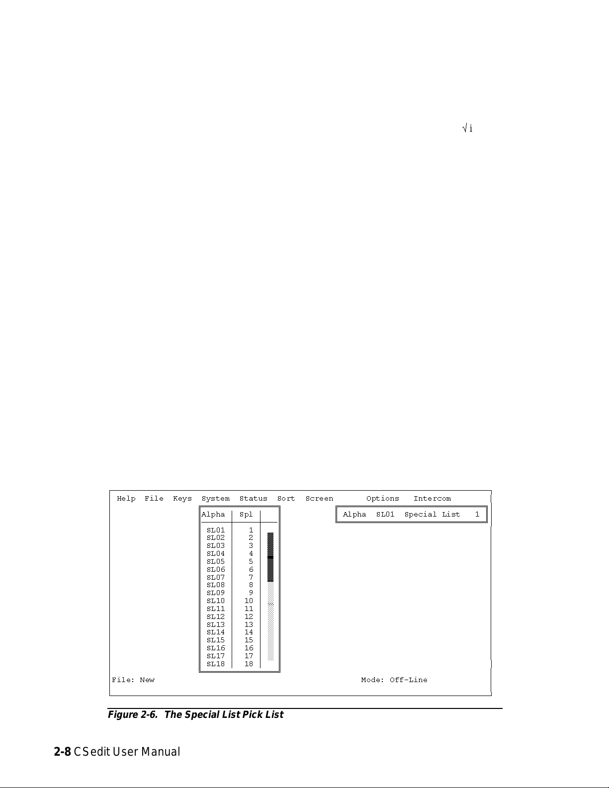
Creating a Special List
A special list is a group of ports that a keypanel operator
can talk and/or listen to by pressing a single key. Special
lists are useful for paging, all-call, group call, all-listen or
group listen.
The following procedure lets you create a special list by
assigning ports to the list. You can also assign a meaningful name for the special list. Once you have configured a
special list, you can assign it to any keypanel key as described starting on page 2-15.
To set up a special list:
1. From the System menu, select “Special Lists” to open
the special list pick list (Figure 2-6). The default Alpha names for special lists are SL01, SL02 etc. As
you configure special lists you will also change the
Alphas to more meaningful names for your intercom
system.
3. Figure 2-7 shows a typical special list edit screen for
special list SL19. To assign ports to the special list,
use the Special List Port Assignments table at the bottom of the screen. Position the cursor in the “S” column next to a port that you want to add to the special
list. Then, use the SPACE BAR (or click with a
mouse) to insert a check markûin the column. In the
example in Figure 2-7, ports 1, 6, 16 and 36 have
been assigned to the special list.
4. Relays* may be assigned to a special list for activation
along with the special list. To assign a relay to a special list, TAB to the Special List Relay Assignments
window and press ENTER. (Or click on the window
with a mouse.) The special list relay assignment
screen should appear (Figure 2-8). Type in the Alpha
names of up to four relays in the relay assignment table at the left side of the screen. Or, use the Relays
pick list at the right side of the screen to enter Alpha
names into the table. In the example in Figure 2-8,
the relays with default names RY02 and RY04 have
been assigned to the special list.
2. To select a special list, highlight it using the cursor
keys, then press the ENTER key (or click on a special list with a mouse). A special list edit screen
should appear (Figure 2-7).
ÚÄÄÄÄÄÄÄÄÄÄÄÄÄÄÄÄÄÄÄÄÄÄÄÄÄÄÄÄÄÄÄÄÄÄÄÄÄÄÄÄÄÄÄÄÄÄÄÄÄÄÄÄÄÄÄÄÄÄÄÄÄÄÄÄÄÄÄÄÄÄÄÄÄÄÄÄÄÄÄÄ¿
³ Help File Keys System Status Sort Screen Options Intercom ³
³ ÉÍÍÍÍÍÍÍÍÍÍÍÍÍÍÍÍ» ÉÍÍÍÍÍÍÍÍÍÍÍÍÍÍÍÍÍÍÍÍÍÍÍÍÍÍÍÍÍÍÍ»³
³ ºAlpha ³ Spl ³ º º Alpha SL01 Special List 1 º³
³ ºÄÄÄÄÄÄÅÄÄÄÄÄÅÄÄĺ ÈÍÍÍÍÍÍÍÍÍÍÍÍÍÍÍÍÍÍÍÍÍÍÍÍÍÍÍÍÍÍͼ³
³ ºSL01³1³º ³
³ º SL02 ³ 2 ³ ² º ³
³ º SL03 ³ 3 ³ ² º ³
³ º SL04 ³ 4 ³ ² º ³
³ º SL05 ³ 5 ³ ² º ³
³ º SL06 ³ 6 ³ ² º ³
³ º SL07 ³ 7 ³ ² º ³
³ º SL08 ³ 8 ³ ° º ³
³ º SL09 ³ 9 ³ ° º ³
³ º SL10 ³ 10 ³ ° º ³
³ º SL11 ³ 11 ³ ° º ³
³ º SL12 ³ 12 ³ ° º ³
³ º SL13 ³ 13 ³ ° º ³
³ º SL14 ³ 14 ³ ° º ³
³ º SL15 ³ 15 ³ ° º ³
³ º SL16 ³ 16 ³ ° º ³
³ º SL17 ³ 17 ³ ° º ³
³ º SL18 ³ 18 ³▼º³
³ ÈÍÍÍÍÍÍÍÍÍÍÍÍÍÍÍͼ ³
³File: New Mode: Off-Line ³
³ ³
ÀÄÄÄÄÄÄÄÄÄÄÄÄÄÄÄÄÄÄÄÄÄÄÄÄÄÄÄÄÄÄÄÄÄÄÄÄÄÄÄÄÄÄÄÄÄÄÄÄÄÄÄÄÄÄÄÄÄÄÄÄÄÄÄÄÄÄÄÄÄÄÄÄÄÄÄÄÄÄÄÄÙ
* The generic term “relay” refers to the digital outputs of
an ADAM-CS Frame (available at J903) or the relay
outputs of an optional UIO-256 or FR9528 Frame.
Figure 2-6. The Special List Pick List
2-8 CSedit User Manual
Page 20
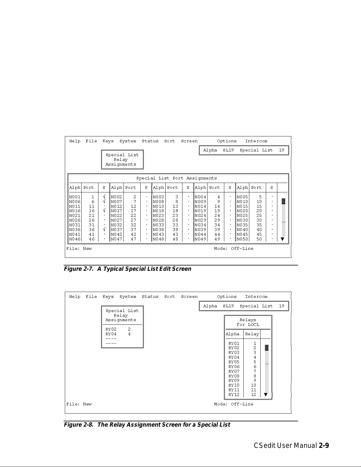
Note To use the Relays pick list to insert relays into
the Special List Relay Assignments table: Position the cursor in the Special List Relay Assignments table at the point where you want to make
the insertion. Then press the TAB key to move
the cursor into the Relays pick list (or if you
have a mouse, just move the mouse cursor over
the pick list). Select a relay Alpha from the pick
list and press ENTER (or click with a mouse).
The selected relay should appear in the Special
List Relay Assignments table.
ÚÄÄÄÄÄÄÄÄÄÄÄÄÄÄÄÄÄÄÄÄÄÄÄÄÄÄÄÄÄÄÄÄÄÄÄÄÄÄÄÄÄÄÄÄÄÄÄÄÄÄÄÄÄÄÄÄÄÄÄÄÄÄÄÄÄÄÄÄÄÄÄÄÄÄÄÄÄÄÄÄ¿
³ Help File Keys System Status Sort Screen Options Intercom ³
³ ÉÍÍÍÍÍÍÍÍÍÍÍÍÍÍÍÍÍÍÍÍÍÍÍÍÍÍÍÍÍÍÍ»³
³ ÉÍÍÍÍÍÍÍÍÍÍÍÍÍÍ» º Alpha SL19 Special List 19 º³
³ º Special List º ÈÍÍÍÍÍÍÍÍÍÍÍÍÍÍÍÍÍÍÍÍÍÍÍÍÍÍÍÍÍÍͼ³
³ º Relay º ³
³ º Assignments º ³
³ ÈÍÍÍÍÍÍÍÍÍÍÍÍÍͼ ³
³ÉÍÍÍÍÍÍÍÍÍÍÍÍÍÍÍÍÍÍÍÍÍÍÍÍÍÍÍÍÍÍÍÍÍÍÍÍÍÍÍÍÍÍÍÍÍÍÍÍÍÍÍÍÍÍÍÍÍÍÍÍÍÍÍÍÍÍÍÍÍÍÍÍÍÍÍÍÍÍ»³
³º Special List Port Assignments º³
³ºÄÄÄÄÂÄÄÄÄÄÂÄÄÄÒÄÄÄÄÂÄÄÄÄÄÂÄÄÄÒÄÄÄÄÂÄÄÄÄÄÂÄÄÄÒÄÄÄÄÂÄÄÄÄÄÂÄÄÄÒÄÄÄÄÂÄÄÄÄÄÂÄÄÄÂÄÄĺ³
³ºAlph³Port ³ S ºAlph³Port ³ S ºAlph³Port ³ S ºAlph³Port ³ S ºAlph³Port ³ S ³ º³
³ºÄÄÄÄÅÄÄÄÄÄÅÄÄÄ×ÄÄÄÄÅÄÄÄÄÄÅÄÄÄ×ÄÄÄÄÅÄÄÄÄÄÅÄÄÄ×ÄÄÄÄÅÄÄÄÄÄÅÄÄÄ×ÄÄÄÄÅÄÄÄÄÄÅÄÄÄÅÄÄĺ³
³ºN001³ 1³ûºN002³ 2³úºN003³ 3³úºN004³ 4³úºN005³ 5³ú³ º³
³ºN006³ 6³ûºN007³ 7³úºN008³ 8³úºN009³ 9³úºN010³ 10³ú³²º³
³ºN011³ 11 ³ ú ºN012³ 12 ³ ú ºN013³ 13 ³ ú ºN014³ 14 ³ ú ºN015³ 15 ³ ú ³ ° º³
³ºN016³ 16 ³ û ºN017³ 17 ³ ú ºN018³ 18 ³ ú ºN019³ 19 ³ ú ºN020³ 20 ³ ú ³ ° º³
³ºN021³ 21 ³ ú ºN022³ 22 ³ ú ºN023³ 23 ³ ú ºN024³ 24 ³ ú ºN025³ 25 ³ ú ³ ° º³
³ºN026³ 26 ³ ú ºN027³ 27 ³ ú ºN028³ 28 ³ ú ºN029³ 29 ³ ú ºN030³ 30 ³ ú ³ ° º³
³ºN031³ 31 ³ ú ºN032³ 32 ³ ú ºN033³ 33 ³ ú ºN034³ 34 ³ ú ºN035³ 35 ³ ú ³ ° º³
³ºN036³ 36 ³ û ºN037³ 37 ³ ú ºN038³ 38 ³ ú ºN039³ 39 ³ ú ºN040³ 40 ³ ú ³ ° º³
³ºN041³ 41 ³ ú ºN042³ 42 ³ ú ºN043³ 43 ³ ú ºN044³ 44 ³ ú ºN045³ 45 ³ ú ³ ° º³
³ºN046³ 46 ³ ú ºN047³ 47 ³ ú ºN048³ 48 ³ ú ºN049³ 49 ³ ú ºN050³ 50 ³ ú ³▼º³
³ÈÍÍÍÍÍÍÍÍÍÍÍÍÍÍÍÍÍÍÍÍÍÍÍÍÍÍÍÍÍÍÍÍÍÍÍÍÍÍÍÍÍÍÍÍÍÍÍÍÍÍÍÍÍÍÍÍÍÍÍÍÍÍÍÍÍÍÍÍÍÍÍÍÍÍÍÍÍͼ³
³File: New Mode: Off-Line ³
³ ³
ÀÄÄÄÄÄÄÄÄÄÄÄÄÄÄÄÄÄÄÄÄÄÄÄÄÄÄÄÄÄÄÄÄÄÄÄÄÄÄÄÄÄÄÄÄÄÄÄÄÄÄÄÄÄÄÄÄÄÄÄÄÄÄÄÄÄÄÄÄÄÄÄÄÄÄÄÄÄÄÄÄÙ
5. Close the Special List Relay Assignments window
when finished assigning relays: either press the ESCAPE key, or click with the right mouse button on
any selectable item in the window.
Note: If desired, you can replace the default relay Al-
pha names with ones that are more meaningful
in your intercom system. See "Using Relays",
page 2-11, to rename relays.
6. To name the special list, TAB to the “Alpha” window
in the upper-right corner of the screen and press ENTER. (Or click on any selectable item in the window
with a mouse.) The name/restriction editor screen
Figure 2-7. A Typical Special List Edit Screen
ÚÄÄÄÄÄÄÄÄÄÄÄÄÄÄÄÄÄÄÄÄÄÄÄÄÄÄÄÄÄÄÄÄÄÄÄÄÄÄÄÄÄÄÄÄÄÄÄÄÄÄÄÄÄÄÄÄÄÄÄÄÄÄÄÄÄÄÄÄÄÄÄÄÄÄÄÄÄÄÄÄ¿
³ Help File Keys System Status Sort Screen Options Intercom ³
³ ÉÍÍÍÍÍÍÍÍÍÍÍÍÍÍÍÍÍÍÍÍÍÍÍÍÍÍÍÍÍÍÍ»³
³ ÉÍÍÍÍÍÍÍÍÍÍÍÍÍÍ» º Alpha SL19 Special List 19 º³
³ º Special List º ÈÍÍÍÍÍÍÍÍÍÍÍÍÍÍÍÍÍÍÍÍÍÍÍÍÍÍÍÍÍÍͼ³
³ º Relay º ÉÍÍÍÍÍÍÍÍÍÍÍÍÍÍÍÍ» ³
³ º Assignments º º Relays º ³
³ ºÄÄÄÄÄÄÄÄÄÄÄÄÄĺ º for LOCL º ³
³ º RY02 2 º ºÍÍÍÍÍÍÑÍÍÍÍÍÑÍÍͺ ³
³ º RY04 4 º ºAlpha ³Relay³ º ³
³ º ---- º ºÄÄÄÄÄÄÅÄÄÄÄÄÅÄÄĺ ³
³ º ---- º º RY01 ³ 1 ³ º ³
³ ÈÍÍÍÍÍÍÍÍÍÍÍÍÍͼ º RY02 ³ 2 ³ ² º ³
³ ºRY03³ 3³°º ³
³ ºRY04³ 4³°º ³
³ ºRY05³ 5³°º ³
³ ºRY06³ 6³°º ³
³ ºRY07³ 7³°º ³
³ ºRY08³ 8³°º ³
³ ºRY09³ 9³°º ³
³ ºRY10³ 10³°º ³
³ ºRY11³ 11³°º ³
³ º RY12 ³ 12 ³▼º³
³ ÈÍÍÍÍÍÍÍÍÍÍÍÍÍÍÍͼ ³
³File: New Mode: Off-Line ³
³ ³
ÀÄÄÄÄÄÄÄÄÄÄÄÄÄÄÄÄÄÄÄÄÄÄÄÄÄÄÄÄÄÄÄÄÄÄÄÄÄÄÄÄÄÄÄÄÄÄÄÄÄÄÄÄÄÄÄÄÄÄÄÄÄÄÄÄÄÄÄÄÄÄÄÄÄÄÄÄÄÄÄÄÙ
Figure 2-8. The Relay Assignment Screen for a Special List
CSedit User Manual 2-9
Page 21

should appear (Figure 2-9). Type in an alpha name
(up to four digits). If desired, type in a different alias
name.
7. To apply or remove restrictions, use the cursor keys or
the mouse to select the desired restriction, then use
the SPACE BAR or click with the mouse to place a
check markûnext to the restriction:
• Spl Access Restricted: A check mark here pre-
vents keypanel operators in your intercom system
from assigning this special list to keys from their
keypanels.
• Spl Univ Scroll Restricted: If your intercom sys-
tem is trunked with other intercom systems, a
check mark here prevents keypanel operators in
the other intercom systems from assigning this
special list to keys from their keypanels.
• Spl CSedit Scroll Restricted: A check mark here
prevents CSedit users in other intercom systems
from assigning this special list in their intercom
systems.
Note As you make changes in this screen, or in any of
the other screens for this special list, you will notice that a check markûis inserted next to “Data
Changed” in the name/restriction editor. This
check mark is a change flag. (See the change
flag description on page 1-4 for further details.)
8. Press the ESCAPE key (or click on any item with the
right mouse button) to return to the special list pick
list when finished configuring a special list. Press the
ESCAPE key again to return to the CSedit menu
screen.
9. After you have configured one or more special lists, proceed to "Keypanel Setup", starting on page 2-15, to
assign the special list to a keypanel key.
10. Remember to save your changes and send them to the
intercom system when finished. (See "Activating a
New File or Sending Changes", page 1-4.)
11. Check special list operation. When the special list key
is pressed, it should be possible to talk and/or listen
to all members of the special list. Also, any relays assigned to the special list should activate.
ÚÄÄÄÄÄÄÄÄÄÄÄÄÄÄÄÄÄÄÄÄÄÄÄÄÄÄÄÄÄÄÄÄÄÄÄÄÄÄÄÄÄÄÄÄÄÄÄÄÄÄÄÄÄÄÄÄÄÄÄÄÄÄÄÄÄÄÄÄÄÄÄÄÄÄÄÄÄÄÄÄ¿
³ Help File Keys System Status Sort Screen Options Intercom ³
³ ÉÍÍÍÍÍÍÍÍÍÍÍÍÍÍÍÍÍÍÍÍÍÍÍÍÍÍÍÍÍÍÍÍ»³
³ º Alpha SL19 Special List 19 º³
³ º Alias SL19 º³
³ º Spl Access Restricted ú º³
³ º Spl Univ Scroll Restricted ú º³
³ º Spl CSedit Scroll Restricted ú º³
³ º Data Changed û º³
³ ÈÍÍÍÍÍÍÍÍÍÍÍÍÍÍÍÍÍÍÍÍÍÍÍÍÍÍÍÍÍÍÍͼ³
³ ³
³ ³
³ ³
³ ³
³ ³
³ ³
³ ³
³ ³
³ ³
³ ³
³ ³
³ ³
³ ³
³ ³
³File: New Mode: Off-Line ³
³ ³
ÀÄÄÄÄÄÄÄÄÄÄÄÄÄÄÄÄÄÄÄÄÄÄÄÄÄÄÄÄÄÄÄÄÄÄÄÄÄÄÄÄÄÄÄÄÄÄÄÄÄÄÄÄÄÄÄÄÄÄÄÄÄÄÄÄÄÄÄÄÄÄÄÄÄÄÄÄÄÄÄÄÙ
Figure 2-9. The Name/Restriction Editor for a Special List
2-10 CSedit User Manual
Page 22

Using Relays
Note: The generic term “relay” refers to the digital out-
puts of an ADAM-CS Frame (available at J903)
or the relay outputs of an optional UIO-256 or
FR9528 Frame. One method of using relays was
already discussed under "Creating a Special
List", page 2-8. There are also two other methods for using relays:
To configure a relay:
1. From the menu bar, select the System menu, then select
“Relays”. The Relay Edit Screen should appear (Figure 2-10). Relays are configured in the Relay Assignments table at the left of the screen. A pick list of
Inputs/Outputs that may be inserted into the table is
shown at the right. The number of available relays
may vary depending on the size and configuration of
your intercom system.
Method 1: The first method provides all-or-one relay activation: a relay can be set to activate whenever anyone
talks to a specified output port, or when a specified user
talks to that port. You could use this method, for example, when a radio transmitter is connected to an intercom
audio output and you want a relay to automatically key
the transmitter for all users or just one specific user. Use
of method 1 is described at right.
Method 2: In the second method, you assign individual
talk keys on selected keypanels to activate relays. Since
talk keys can be programmed to activate two types of
communication simultaneously, method 2 can also be
used like method 1: for example, to talk to a transmitter
and key transmitter output. The difference is that, using
method 2, you define selected keys that can talk to a particular output and activate a relay. To use method 2, assign relay names and impose restrictions as described in
steps 1-3 which follow. Then, refer to "Keypanel Setup",
starting on page 2-15, to assign the relays to keys on selected keypanels.
2. Default relay Alpha and Alias names are RY01, RY02
etc. To change a relay’s Alpha name, position the cursor in the Alpha column and type in the desired name
(up to 4-characters). When you change a relay’s Alpha name and move to a new location in the table,
you will notice that the relay’s Alias name is also
changed*. If your intercom system is trunked to other
intercom systems, you can change this Alias name to
a different name that will be more meaningful to users in the external intercom systems.
Note When you make any change to a relay definition
and move to a new position, you will notice that
a check markûis inserted in the “Chg” column.
This check mark is a change flag. (See the
change flag description on page 1-4 for further
details.)
* Except when an Alias has already been entered that is
different from the Alpha. In this case, the Alias will
not change whenever the Alpha is changed.
ÚÄÄÄÄÄÄÄÄÄÄÄÄÄÄÄÄÄÄÄÄÄÄÄÄÄÄÄÄÄÄÄÄÄÄÄÄÄÄÄÄÄÄÄÄÄÄÄÄÄÄÄÄÄÄÄÄÄÄÄÄÄÄÄÄÄÄÄÄÄÄÄÄÄÄÄÄÄÄÄÄ¿
³ Help File Keys System Status Sort Screen Options Intercom ³
³ ÉÍÍÍÍÍÍÍÍÍÍÍÍÍÍÍÍÍÍÍÍÍÍÍÍÍÍÍÍÍÍÍÍÍÍÍÍÍÍÍÍÍÍÍÍÍÍÍÍÍÍÍÍÍÍÍ» ÉÍÍÍÍÍÍÍÍÍÍÍÍÍÍÍÍ» ³
³ º Relay Assignments º º Inputs/Outputs º ³
³ ºÍÍÍÍÍÍÑÍÍÍÍÍÍÑÍÍÍÍÑÍÍÍÍÑÍÍÍÍÍÑÍÍÍÍÍÍÍÍÍÍÑÍÍÍÍÍÍÍÍÍÍÑÍÍͺ ºÍÍÍÍÍÍÑÍÍÍÍÍÑÍÍͺ ³
³ ºAlpha ³Alias ³ Rel³Chg ³ AUC ³ Input ³ Output ³ º ºAlpha ³Port ³ º ³
³ ºÄÄÄÄÄÄÅÄÄÄÄÄÄÅÄÄÄÄÅÄÄÄÄÅÄÄÄÄÄÅÄÄÄÄÄÄÄÄÄÄÅÄÄÄÄÄÄÄÄÄÄÅÄÄĺ ºÄÄÄÄÄÄÅÄÄÄÄÄÅÄÄĺ ³
³ º RY01 ³RY01 ³ 1 ³ û ³ ûûû ³N017 17 ³N019 19 ³ º º N017 ³ 17 ³▲º³
³ºRY02³RY02 ³ 2³ û³ûûû³---- All³N020 20³²º ºN018³ 18³°º³
³ºRY03³RY03 ³ 3³ ú³úûû³---- ³---- ³²º ºN019³ 19³²º³
³ºRY04³RY04 ³ 4³ ú³úûû³---- ³---- ³°º ºN020³ 20³°º³
³ºRY05³RY05 ³ 5³ ú³úûû³---- ³---- ³°º ºN021³ 21³°º³
³ºRY06³RY06 ³ 6³ ú³úûû³---- ³---- ³°º ºN022³ 22³°º³
³ºRY07³RY07 ³ 7³ ú³úûû³---- ³---- ³°º ºN023³ 23³°º³
³ºRY08³RY08 ³ 8³ ú³úûû³---- ³---- ³°º ºN024³ 24³°º³
³ºRY09³RY09 ³ 9³ ú³úûû³---- ³---- ³°º ºN025³ 25³°º³
³ºRY10³RY10 ³10³ ú³úûû³---- ³---- ³°º ºN026³ 26³°º³
³ºRY11³RY11 ³11³ ú³úûû³---- ³---- ³°º ºN027³ 27³°º³
³ºRY12³RY12 ³12³ ú³úûû³---- ³---- ³°º ºN028³ 28³°º³
³ºRY13³RY13 ³13³ ú³úûû³---- ³---- ³°º ºN029³ 29³°º³
³ºRY14³RY14 ³14³ ú³úûû³---- ³---- ³°º ºN030³ 30³°º³
³ºRY15³RY15 ³15³ ú³úûû³---- ³---- ³°º ºN031³ 31³°º³
³ º RY16 ³RY16 ³ 16 ³ ú ³ úûû ³---- ³---- ³▼º º N032 ³ 32 ³▼º³
³ ÈÍÍÍÍÍÍÍÍÍÍÍÍÍÍÍÍÍÍÍÍÍÍÍÍÍÍÍÍÍÍÍÍÍÍÍÍÍÍÍÍÍÍÍÍÍÍÍÍÍÍÍÍÍÍͼ ÈÍÍÍÍÍÍÍÍÍÍÍÍÍÍÍͼ ³
³File: New Mode: Off-Line ³
³ ³
ÀÄÄÄÄÄÄÄÄÄÄÄÄÄÄÄÄÄÄÄÄÄÄÄÄÄÄÄÄÄÄÄÄÄÄÄÄÄÄÄÄÄÄÄÄÄÄÄÄÄÄÄÄÄÄÄÄÄÄÄÄÄÄÄÄÄÄÄÄÄÄÄÄÄÄÄÄÄÄÄÄÙ
Figure 2-10. The Relay Edit Screen
CSedit User Manual 2-11
Page 23

3. To apply restrictions to a relay, position the cursor in
the “AUC” column under A, U or C. Then, use the
SPACE BAR or click with a mouse to place or remove check marks as follows:
A Access Restricted: A check mark under “A” pre-
vents keypanel operators in your intercom system from assigning this relay to keys from their
keypanels.
4. Associate a relay with an audio output port (for example, the output port to which a transmitter is connected). Position the cursor in the “Output” column
of the Relay Assignments table and enter the name of
the output port (or use the pick list at the right side of
the screen.) In the example in Figure 2-10, relay
RY01 has been associated with output port N019.
5. Select a single user or all users for relay activation:
U Univ Scroll Restricted: If your intercom system is
trunked with other intercom systems, a check
mark under “U” will prevent keypanel operators
in the other intercom systems from assigning
this relay to keys from their keypanels. Normally
you will want to restrict outside keypanel access,
so a check mark is automatically placed in this
column for you.
C CSedit Scroll Restricted: A check mark under “C”
prevents CSedit users in other intercom systems
from assigning this relay in their intercom systems. Normally you will want to restrict outside
CSedit access, so a check mark is automatically
placed in this column for you.
Note The following steps are required only if you want
a relay to activate whenever a particular audio
output port is called. If, on the other hand, you
wish to assign a relay for activation by a specific
keypanel key, skip the following steps and proceed to "Keypanel Setup", starting on page 2-15.
Single User: Position the cursor in the left side of the “Input” column and type the Alpha name of the user (or
select a name from the pick list at the right side of
the screen). In the example in Figure 2-10, only the
user at port N017 will activate relay RY01 when talking to port N019.
All Users: Position the cursor in the right side of the “Input” column and press the SPACE BAR (or click
with a mouse) to enter the word “All” in the column.
In the example in Figure 2-10, all users will activate
relay RY02 when talking to output port N020.
6. Press the ESCAPE key (or click on any selectable item
with the right mouse button) to exit the relay edit
screen after relays have been set up.
7. Remember to save your changes and send them to the
intercom system when finished. (See "Activating a
New File or Sending Changes", page 1-4.)
2-12 CSedit User Manual
Page 24
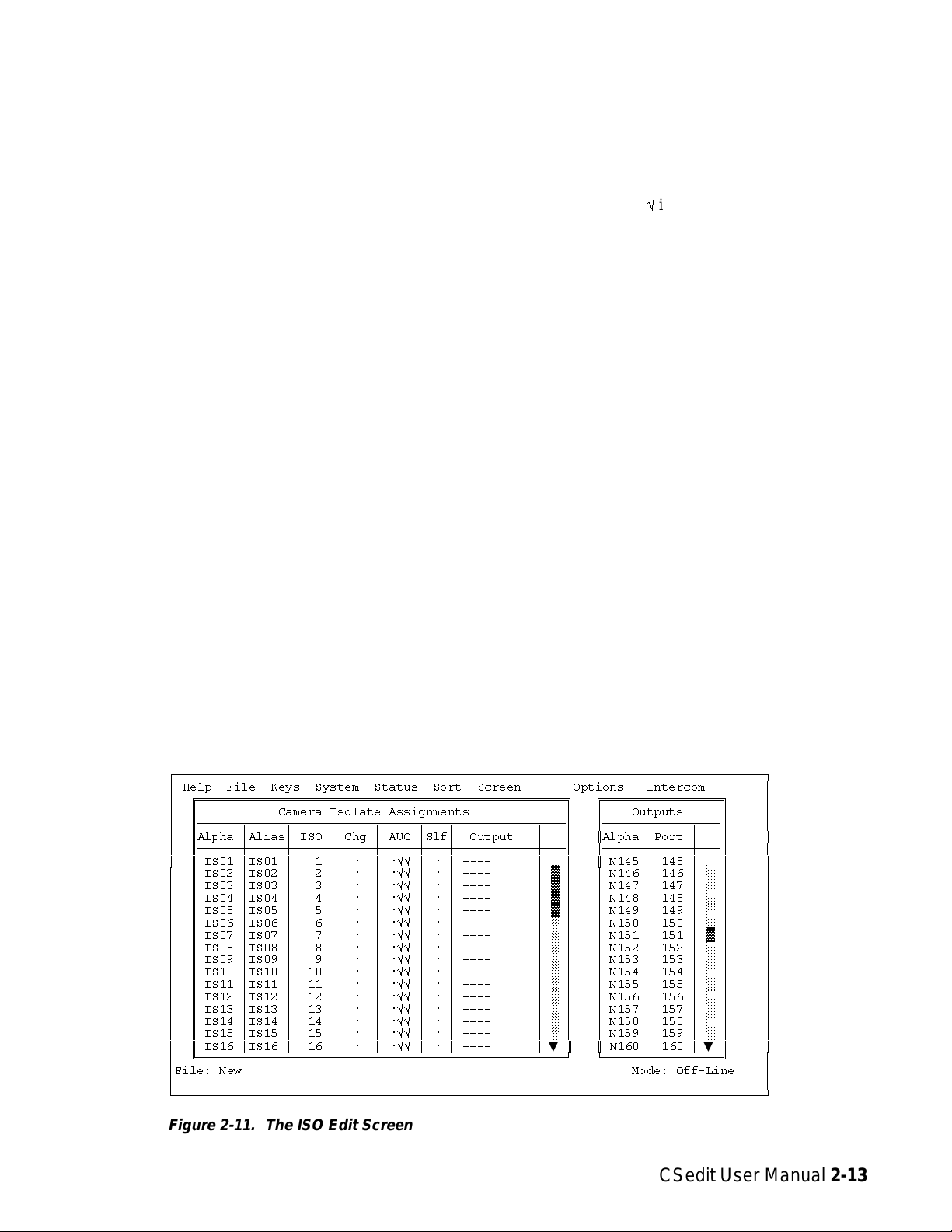
Creating a Camera ISO Channel
An ISO channel is a special type of communication
where a keypanel user can press a single key to completely isolate, or cut off, all communications to a particular intercom station and establish a private conversation
with that intercom station. The name “Camera ISO” refers to a broadcasting application where, for example, a
director needs to talk to one specific camera on a camera
party line without interruptions from other personnel on
the party line. Other personnel on the party line can carry
on conversation as usual, but the isolated camera will not
hear the party line while the ISO is active. Releasing the
ISO key re-establishes normal communications. The following procedure lets you tell CSedit which port you
want to isolate. You can also assign a meaningful name
for the ISO and restrict access to it. Once you have configured an ISO, you can let any keypanel user talk to it by
simply assigning the ISO to a key on their keypanel.
change this Alias name to a different name that will
be more meaningful to users in the external intercom
systems.
Note When you make any change to an ISO definition
and move to a new position, you will notice that
a check markûis inserted in the “Chg” column.
This check mark is a change flag. (See the
change flag description on page 1-4 for further
details.)
3. To apply restrictions to an ISO, position the cursor in
the “AUC” column under A, U or C. Then, use the
SPACE BAR or click with a mouse to place or remove check marks as follows:
A Access Restricted: A check mark under “A” pre-
vents keypanel operators in your intercom system from assigning this ISO to keys from their
keypanels.
To set up an ISO:
1. From the menu bar, select the System menu, then select
“ISOs”. The ISO edit screen should appear (Figure 2-
11). ISO’s are set up in the Camera Isolate Assignments table at the left side of the screen. An Outputs
pick list appears at the right side of the screen.
2. Default ISO Alpha and Alias names are IS01, IS02 etc.
To change an ISO’s Alpha name, position the cursor
in the Alpha column and type in a 4-character name
that will be meaningful to users in your intercom system. When you change an ISO’s Alpha name and
move to a new location in the table, you will notice
that the Alias name is also changed. If your intercom
system is trunked to other intercom systems, you can
ÚÄÄÄÄÄÄÄÄÄÄÄÄÄÄÄÄÄÄÄÄÄÄÄÄÄÄÄÄÄÄÄÄÄÄÄÄÄÄÄÄÄÄÄÄÄÄÄÄÄÄÄÄÄÄÄÄÄÄÄÄÄÄÄÄÄÄÄÄÄÄÄÄÄÄÄÄÄÄÄÄ¿
³ Help File Keys System Status Sort Screen Options Intercom ³
³ ÉÍÍÍÍÍÍÍÍÍÍÍÍÍÍÍÍÍÍÍÍÍÍÍÍÍÍÍÍÍÍÍÍÍÍÍÍÍÍÍÍÍÍÍÍÍÍÍÍÍÍ» ÉÍÍÍÍÍÍÍÍÍÍÍÍÍÍÍÍ» ³
³ º Camera Isolate Assignments º º Outputs º ³
³ ºÍÍÍÍÍÍÑÍÍÍÍÍÑÍÍÍÍÍÑÍÍÍÍÍÑÍÍÍÍÍÑÍÍÍÑÍÍÍÍÍÍÍÍÍÍÍÑÍÍͺ ºÍÍÍÍÍÍÑÍÍÍÍÍÑÍÍͺ ³
³ ºAlpha ³Alias³ ISO ³ Chg ³ AUC ³Slf³ Output ³ º ºAlpha ³Port ³ º ³
³ ºÄÄÄÄÄÄÅÄÄÄÄÄÅÄÄÄÄÄÅÄÄÄÄÄÅÄÄÄÄÄÅÄÄÄÅÄÄÄÄÄÄÄÄÄÄÄÅÄÄĺ ºÄÄÄÄÄÄÅÄÄÄÄÄÅÄÄĺ ³
³ º IS01 ³IS01 ³ 1 ³ ú ³ úûû ³ ú ³ ---- ³ º º N145 ³ 145 ³▲º³
³ ºIS02³IS02³ 2³ ú ³úûû³ú³---- ³²º ºN146³146³°º ³
³ ºIS03³IS03³ 3³ ú ³úûû³ú³---- ³²º ºN147³147³°º ³
³ ºIS04³IS04³ 4³ ú ³úûû³ú³---- ³²º ºN148³148³°º ³
³ ºIS05³IS05³ 5³ ú ³úûû³ú³---- ³²º ºN149³149³°º ³
³ ºIS06³IS06³ 6³ ú ³úûû³ú³---- ³°º ºN150³150³°º ³
³ ºIS07³IS07³ 7³ ú ³úûû³ú³---- ³°º ºN151³151³²º ³
³ ºIS08³IS08³ 8³ ú ³úûû³ú³---- ³°º ºN152³152³°º ³
³ ºIS09³IS09³ 9³ ú ³úûû³ú³---- ³°º ºN153³153³°º ³
³ ºIS10³IS10³ 10³ ú ³úûû³ú³---- ³°º ºN154³154³°º ³
³ ºIS11³IS11³ 11³ ú ³úûû³ú³---- ³°º ºN155³155³°º ³
³ ºIS12³IS12³ 12³ ú ³úûû³ú³---- ³°º ºN156³156³°º ³
³ ºIS13³IS13³ 13³ ú ³úûû³ú³---- ³°º ºN157³157³°º ³
³ ºIS14³IS14³ 14³ ú ³úûû³ú³---- ³°º ºN158³158³°º ³
³ ºIS15³IS15³ 15³ ú ³úûû³ú³---- ³°º ºN159³159³°º ³
³ º IS16 ³IS16 ³ 16 ³ ú ³ úûû ³ ú ³ ---- ³▼º ºN160³160³▼º³
³ ÈÍÍÍÍÍÍÍÍÍÍÍÍÍÍÍÍÍÍÍÍÍÍÍÍÍÍÍÍÍÍÍÍÍÍÍÍÍÍÍÍÍÍÍÍÍÍÍÍÍͼ ÈÍÍÍÍÍÍÍÍÍÍÍÍÍÍÍͼ ³
³File: New Mode: Off-Line ³
³ ³
ÀÄÄÄÄÄÄÄÄÄÄÄÄÄÄÄÄÄÄÄÄÄÄÄÄÄÄÄÄÄÄÄÄÄÄÄÄÄÄÄÄÄÄÄÄÄÄÄÄÄÄÄÄÄÄÄÄÄÄÄÄÄÄÄÄÄÄÄÄÄÄÄÄÄÄÄÄÄÄÄÄÙ
U Univ Scroll Restricted: If your intercom system is
trunked with other intercom systems, a check
mark under “U” will prevent keypanel operators
in the other intercom systems from assigning
this ISO to keys from their keypanels. Normally
you will want to restrict outside keypanel access,
so a check mark is automatically placed in this
column for you.
C CSedit Scroll Restricted: A check mark under “C”
prevents CSedit users in other intercom systems
from assigning this ISO in their intercom systems. Normally you will want to restrict outside
CSedit access, so a check mark is automatically
placed in this column for you.
Figure 2-11. The ISO Edit Screen
CSedit User Manual 2-13
Page 25

4. The “self” column (Slf) is used to also isolate the keypanel operator during ISO activation. This insures
that the keypanel operator is not disturbed during a
critical ISO operation. Use the SPACE BAR or click
with a mouse to place or remove a check mark in this
column.
5. To designate the port that will be isolated during ISO activation, move the cursor to the Output column and
enter the Alpha name of the desired port (or select
the desired Alpha from the pick list at the right side
of the screen).
6. When you are done setting up an ISO, press the ESCAPE key to return to the menu bar. (Or, click on
any selectable item with the right button on a mouse.)
7. Assign the ISO to a key on a keypanel as described under "Keypanel Setup", starting on page 2-15.
8. Remember to save your changes and send them to the
intercom system when finished. (See "Activating a
New File or Sending Changes", page 1-4.)
2-14 CSedit User Manual
Page 26

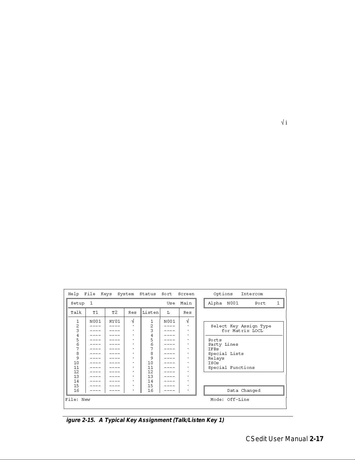
Keypanel Setup and Trunking Port
Allocation
Keypanel Setup: Selecting a Keypanel
For Editing
Once you have assigned alphas and configured any party
lines, IFB’s, ISO’s etc. that will be needed, you can assign the keys on keypanels to meet each user’s communication needs. As you set up keypanels, you can impose
restrictions on each keypanel to prevent the keypanel operator from changing key assignments from their keypanels. You can also impose scroll restrictions to prevent
keypanel access from external intercom systems. Finally,
for each keypanel, you can assign priority levels for access to IFB’s and for access to limited trunking lines. To
use a port as a trunking port, you simply turn on all restriction flags and leave all keys unassigned. (The restriction flags are discussed in detail on page 2-20.)
Important
The following paragraphs walk you through the process
of configuring a keypanel. However, it is recommended
that you read through the next few pages before you start.
Pay particular attention to the sections describing the
Auto-Follow feature (page 2-18) and the Copy and Paste
Screen feature (page 2-19). By using these two features,
you may be able to save considerable time with listen key
assignments.
From the menu bar, select the Keys menu, then select
“Ports”. The ports pick list should appear (Figure 2-12. If
you assigned names for ports (as described on page 2-1)
these names will appear in the Alpha column of the pick
list in place of the default Alpha names N001, N002 etc.
shown below.
To select a port for editing, select its Alpha name and
press the ENTER key (or click on a port with a mouse).
If your intercom is not trunked, the keypanel edit screen
for the local intercom (Matrix LOCL) will display (Figure 2-13). If your intercom system is trunked to other intercom systems, the keypanel edit screen will look like
Figure 2-14.
ÚÄÄÄÄÄÄÄÄÄÄÄÄÄÄÄÄÄÄÄÄÄÄÄÄÄÄÄÄÄÄÄÄÄÄÄÄÄÄÄÄÄÄÄÄÄÄÄÄÄÄÄÄÄÄÄÄÄÄÄÄÄÄÄÄÄÄÄÄÄÄÄÄÄÄÄÄÄÄÄÄ¿
³ Help File Keys System Status Sort Screen Options Intercom ³
³ ÉÍÍÍÍÍÍÍÍÍÍÍÍÍÍÍÍ» ÉÍÍÍÍÍÍÍÍÍÍÍÍÍÍÍÍÍÍÍÍÍÍÍÍÍÍÍÍ»³
³ ºAlpha ³Port ³ º º Alpha N001 Port 1 º³
³ ºÄÄÄÄÄÄÅÄÄÄÄÄÅÄÄĺ ÈÍÍÍÍÍÍÍÍÍÍÍÍÍÍÍÍÍÍÍÍÍÍÍÍÍÍÍͼ³
³ ºN001³1³º ³
³ º N002 ³ 2 ³ ² º ³
³ º N003 ³ 3 ³ ° º ³
³ º N004 ³ 4 ³ ° º ³
³ º N005 ³ 5 ³ ° º ³
³ º N006 ³ 6 ³ ° º ³
³ º N007 ³ 7 ³ ° º ³
³ º N008 ³ 8 ³ ° º ³
³ º N009 ³ 9 ³ ° º ³
³ º N010 ³ 10 ³ ° º ³
³ º N011 ³ 11 ³ ° º ³
³ º N012 ³ 12 ³ ° º ³
³ º N013 ³ 13 ³ ° º ³
³ º N014 ³ 14 ³ ° º ³
³ º N015 ³ 15 ³ ° º ³
³ º N016 ³ 16 ³ ° º ³
³ º N017 ³ 17 ³ ° º ³
³ º N018 ³ 18 ³▼º³
³ ÈÍÍÍÍÍÍÍÍÍÍÍÍÍÍÍͼ ³
³File: New Mode: Off-Line ³
³ ³
ÀÄÄÄÄÄÄÄÄÄÄÄÄÄÄÄÄÄÄÄÄÄÄÄÄÄÄÄÄÄÄÄÄÄÄÄÄÄÄÄÄÄÄÄÄÄÄÄÄÄÄÄÄÄÄÄÄÄÄÄÄÄÄÄÄÄÄÄÄÄÄÄÄÄÄÄÄÄÄÄÄÙ
Figure 2-12. The Ports Pick List for Keypanel Setup
CSedit User Manual 2-15
Page 27

Note For trunked intercom systems only. You must select an intercom system and retrieve the pick lists from that inter-
com system before assigning keys. To do this, TAB to the window titled “Select Key Assign Matrix” (Figure 2-14).
Use the cursor keys to select the desired intercom system, then press ENTER. (If you are using a mouse, simply
click on the desired intercom system name.) Once the pick lists have been retrieved, the edit screen will look just
like the local matrix screen (Figure 2-13). Note that the name of the selected intercom system will appear in the
lower-right corner of the screen.
ÚÄÄÄÄÄÄÄÄÄÄÄÄÄÄÄÄÄÄÄÄÄÄÄÄÄÄÄÄÄÄÄÄÄÄÄÄÄÄÄÄÄÄÄÄÄÄÄÄÄÄÄÄÄÄÄÄÄÄÄÄÄÄÄÄÄÄÄÄÄÄÄÄÄÄÄÄÄÄÄÄ¿
³ Help File Keys System Status Sort Screen Options Intercom ³
³ÉÍÍÍÍÍÍÍÍÍÍÍÍÍÍÍÍÍÍÍÍÍÍÍÍÍÍÍÍÍÍÍÍÍÍÍÍÍÍÍÍÍÍÍÍÍÍ» ÉÍÍÍÍÍÍÍÍÍÍÍÍÍÍÍÍÍÍÍÍÍÍÍÍÍÍÍÍ»³
³º Setup 1 Use Main º º Alpha N001 Port 1 º³
³ºÍÍÍÍÍÍÑÍÍÍÍÍÍÑÍÍÍÍÍÍÑÍÍÍÍÍËÍÍÍÍÍÍÑÍÍÍÍÍÍÑÍÍÍÍͺ ÈÍÍÍÍÍÍÍÍÍÍÍÍÍÍÍÍÍÍÍÍÍÍÍÍÍÍÍͼ³
³º Talk ³ T1 ³ T2 ³ Res ºListen³ L ³ Res º ³
³ºÄÄÄÄÄÄÅÄÄÄÄÄÄÅÄÄÄÄÄÄÅÄÄÄÄÄ×ÄÄÄÄÄÄÅÄÄÄÄÄÄÅÄÄÄÄĺ ³
³º 1 ³ ---- ³ ---- ³ ú º 1 ³ ---- ³ ú º ÚÄÄÄÄÄÄÄÄÄÄÄÄÄÄÄÄÄÄÄÄÄÄÄÄÄÄÄÄ¿³
³º 2 ³ ---- ³ ---- ³ ú º 2 ³ ---- ³ ú º ³ Select Key Assign Type ³³
³º 3 ³ ---- ³ ---- ³ ú º 3 ³ ---- ³ ú º ³ for Matrix LOCL ³³
³º 4 ³ ---- ³ ---- ³ ú º 4 ³ ---- ³ ú º ³ÄÄÄÄÄÄÄÄÄÄÄÄÄÄÄÄÄÄÄÄÄÄÄÄÄÄÄij³
³º 5 ³ ---- ³ ---- ³ ú º 5 ³ ---- ³ ú º ³ Ports ³³
³º 6 ³ ---- ³ ---- ³ ú º 6 ³ ---- ³ ú º ³ Party Lines ³³
³º 7 ³ ---- ³ ---- ³ ú º 7 ³ ---- ³ ú º ³ IFBs ³³
³º 8 ³ ---- ³ ---- ³ ú º 8 ³ ---- ³ ú º ³ Special Lists ³³
³º 9 ³ ---- ³ ---- ³ ú º 9 ³ ---- ³ ú º ³ Relays ³³
³º 10 ³ ---- ³ ---- ³ ú º 10 ³ ---- ³ ú º ³ ISOs ³³
³º 11 ³ ---- ³ ---- ³ ú º 11 ³ ---- ³ ú º ³ Special Functions ³³
³º 12 ³ ---- ³ ---- ³ ú º 12 ³ ---- ³ ú º ÀÄÄÄÄÄÄÄÄÄÄÄÄÄÄÄÄÄÄÄÄÄÄÄÄÄÄÄÄÙ³
³º 13 ³ ---- ³ ---- ³ ú º 13 ³ ---- ³ ú º ³
³º 14 ³ ---- ³ ---- ³ ú º 14 ³ ---- ³ ú º ³
³º 15 ³ ---- ³ ---- ³ ú º 15 ³ ---- ³ ú º ÉÍÍÍÍÍÍÍÍÍÍÍÍÍÍÍÍÍÍÍÍÍÍÍÍÍÍÍÍ»³
³º 16 ³ ---- ³ ---- ³ ú º 16 ³ ---- ³ ú º º Data Changed º³
³ÈÍÍÍÍÍÍÍÍÍÍÍÍÍÍÍÍÍÍÍÍÍÍÍÍÍÍÍÍÍÍÍÍÍÍÍÍÍÍÍÍÍÍÍÍÍͼ ÈÍÍÍÍÍÍÍÍÍÍÍÍÍÍÍÍÍÍÍÍÍÍÍÍÍÍÍͼ³
³File: New Mode: Off-Line ³
³ ³
ÀÄÄÄÄÄÄÄÄÄÄÄÄÄÄÄÄÄÄÄÄÄÄÄÄÄÄÄÄÄÄÄÄÄÄÄÄÄÄÄÄÄÄÄÄÄÄÄÄÄÄÄÄÄÄÄÄÄÄÄÄÄÄÄÄÄÄÄÄÄÄÄÄÄÄÄÄÄÄÄÄÙ
Figure 2-13. A Keypanel Edit Screen for the Local Intercom System
ÚÄÄÄÄÄÄÄÄÄÄÄÄÄÄÄÄÄÄÄÄÄÄÄÄÄÄÄÄÄÄÄÄÄÄÄÄÄÄÄÄÄÄÄÄÄÄÄÄÄÄÄÄÄÄÄÄÄÄÄÄÄÄÄÄÄÄÄÄÄÄÄÄÄÄÄÄÄÄÄÄ¿
³ Help File Keys System Status Sort Screen Options Intercom ³
³ÉÍÍÍÍÍÍÍÍÍÍÍÍÍÍÍÍÍÍÍÍÍÍÍÍÍÍÍÍÍÍÍÍÍÍÍÍÍÍÍÍÍÍÍÍÍÍ» ÉÍÍÍÍÍÍÍÍÍÍÍÍÍÍÍÍÍÍÍÍÍÍÍÍÍÍÍÍ»³
³º Setup 1 Use Main º º Alpha N001 Port 1 º³
³ºÍÍÍÍÍÍÑÍÍÍÍÍÍÑÍÍÍÍÍÍÑÍÍÍÍÍËÍÍÍÍÍÍÑÍÍÍÍÍÍÑÍÍÍÍͺ ÈÍÍÍÍÍÍÍÍÍÍÍÍÍÍÍÍÍÍÍÍÍÍÍÍÍÍÍͼ³
³º Talk ³ T1 ³ T2 ³ Res ºListen³ L ³ Res º ³
³ºÄÄÄÄÄÄÅÄÄÄÄÄÄÅÄÄÄÄÄÄÅÄÄÄÄÄ×ÄÄÄÄÄÄÅÄÄÄÄÄÄÅÄÄÄÄĺ ³
³º 1 ³ ---- ³ ---- ³ ú º 1 ³ ---- ³ ú º ÚÄÄÄÄÄÄÄÄÄÄÄÄÄÄÄÄÄÄÄÄÄÄÄÄÄÄÄÄ¿³
³º 2 ³ ---- ³ ---- ³ ú º 2 ³ ---- ³ ú º ³ Select Key Assign Matrix ³³
³º 3 ³ ---- ³ ---- ³ ú º 3 ³ ---- ³ ú º ³ÄÄÄÄÄÄÄÄÄÄÄÄÄÄÄÄÄÄÄÄÄÄÄÄÂÄÄij³
³º 4 ³ ---- ³ ---- ³ ú º 4 ³ ---- ³ ú º ³ LOCL ³ ³³
³º 5 ³ ---- ³ ---- ³ ú º 5 ³ ---- ³ ú º ³ NEWS ³ ² ³³
³º 6 ³ ---- ³ ---- ³ ú º 6 ³ ---- ³ ú º ³ 8H ³ ² ³³
³º 7 ³ ---- ³ ---- ³ ú º 7 ³ ---- ³ ú º ³ 8G ³ ² ³³
³º 8 ³ ---- ³ ---- ³ ú º 8 ³ ---- ³ ú º ³ 6A ³ ² ³³
³º 9 ³ ---- ³ ---- ³ ú º 9 ³ ---- ³ ú º ³ WNBC ³ ² ³³
³º 10 ³ ---- ³ ---- ³ ú º 10 ³ ---- ³ ú º ³ WASH ³ ² ³³
³º 11 ³ ---- ³ ---- ³ ú º 11 ³ ---- ³ ú º ³ CNBC ³ ³³
³º 12 ³ ---- ³ ---- ³ ú º 12 ³ ---- ³ ú º ÀÄÄÄÄÄÄÄÄÄÄÄÄÄÄÄÄÄÄÄÄÄÄÄÄÄÄÄÄÙ³
³º 13 ³ ---- ³ ---- ³ ú º 13 ³ ---- ³ ú º ³
³º 14 ³ ---- ³ ---- ³ ú º 14 ³ ---- ³ ú º ³
³º 15 ³ ---- ³ ---- ³ ú º 15 ³ ---- ³ ú º ÉÍÍÍÍÍÍÍÍÍÍÍÍÍÍÍÍÍÍÍÍÍÍÍÍÍÍÍÍ»³
³º 16 ³ ---- ³ ---- ³ ú º 16 ³ ---- ³ ú º º Data Changed º³
³ÈÍÍÍÍÍÍÍÍÍÍÍÍÍÍÍÍÍÍÍÍÍÍÍÍÍÍÍÍÍÍÍÍÍÍÍÍÍÍÍÍÍÍÍÍÍͼ ÈÍÍÍÍÍÍÍÍÍÍÍÍÍÍÍÍÍÍÍÍÍÍÍÍÍÍÍͼ³
³File: New Mode: Off-Line ³
³ Assign: LOCL ---- ³
ÀÄÄÄÄÄÄÄÄÄÄÄÄÄÄÄÄÄÄÄÄÄÄÄÄÄÄÄÄÄÄÄÄÄÄÄÄÄÄÄÄÄÄÄÄÄÄÄÄÄÄÄÄÄÄÄÄÄÄÄÄÄÄÄÄÄÄÄÄÄÄÄÄÄÄÄÄÄÄÄÄÙ
Figure 2-14. A Keypanel Edit Screen for a Trunked Intercom System
2-16 CSedit User Manual
Page 28
Keypanel Setup: The Setup Table
The setup table is located at the left side of the keypanel
edit screen. When the setup table is highlighted, you can
use the PAGE UP/DOWN keys to select setup pages 1
through 4. Each setup page assigns up to 16 talk and listen key pairs. The currently selected setup page number
displays at the upper-left corner of the setup table ("Setup
1", "Setup 2" etc.).
can be used to define a secondary key assignment (called
a level 2 talk key assignment) to activate along with the
level 1 assignment. A talk key that activates two devices
is called a "stacked talk key". For example, you could assign talk level 1 to talk to a two-way radio, and then assign talk level 2 to activate a relay to key the radio during
transmit. In the example in Figure 2-15, port N001 is the
level 1 assignment and relay RY01 is the level 2 assignment for talk key 1.
Each setup page can be assigned and used by either the
main keypanel or any connected expansion panel. Setup
page usage displays at the upper-right corner of the setup
table. In Figure 2-15, for example, setup page 1 is being
used by the main keypanel ("Use Main"). If this setup
page was assigned to an expansion panel, "Use Exp1",
"Use: Exp2" etc. would display. (Setup page assignment
is discussed on page 2-21.) The following procedures will
first describe how to assign individual keys in the setup
pages. Then assigning the setup pages to panels will be
described.
Keypanel Setup: Key Assignments and
Key Restrictions
Talk Key Assignments
Talk keys are numbered from 1 to 16 along the left side
of the setup table. For each key, there is a "T1" and "T2"
assignment. The "T1" column is where you make the normal key assignment (also called a level 1 talk key assignment). The assignment that you make in this column will
appear in the alpha-numeric display on the keypanel, and
this is the person, port, party line etc. that you will normally talk to when the key is pressed. The "T2" column
To prevent the keypanel user from changing a talk key assignment from the keypanel, position the cursor in the
“Res” (restrict) column next to the "T2" column and press
the SPACE BAR to place a check markûin the column.
Listen Key Assignments
Listen keys are assigned and restricted just like talk keys.
In the example in Figure 2-15, listen key 1 has been assigned to listen to port N001. Also, the key has been restricted to prevent the keypanel operator from reassigning
it. (Note: You can save much setup time by using special
functions for most listen key assignments. See the description of special functions, page 2-18.)
Important Notes About Key Assignments
Main panel vs expansion panel usage for all types of
panels: If a setup page is used by the main keypanel, do
not assign key 16, as this is the Incoming Messages key
(also called "call waiting"). If a setup page is used by an
expansion panel, key 16 may be assigned.
KP-90 and EKP-90 series keypanels and expansion
panels with 16 keys: the left-most key on the panel corre-
sponds to key 1 in the setup table.
ÚÄÄÄÄÄÄÄÄÄÄÄÄÄÄÄÄÄÄÄÄÄÄÄÄÄÄÄÄÄÄÄÄÄÄÄÄÄÄÄÄÄÄÄÄÄÄÄÄÄÄÄÄÄÄÄÄÄÄÄÄÄÄÄÄÄÄÄÄÄÄÄÄÄÄÄÄÄÄÄÄ¿
³ Help File Keys System Status Sort Screen Options Intercom ³
³ÉÍÍÍÍÍÍÍÍÍÍÍÍÍÍÍÍÍÍÍÍÍÍÍÍÍÍÍÍÍÍÍÍÍÍÍÍÍÍÍÍÍÍÍÍÍÍ» ÉÍÍÍÍÍÍÍÍÍÍÍÍÍÍÍÍÍÍÍÍÍÍÍÍÍÍÍÍ»³
³º Setup 1 Use Main º º Alpha N001 Port 1 º³
³ºÍÍÍÍÍÍÑÍÍÍÍÍÍÑÍÍÍÍÍÍÑÍÍÍÍÍËÍÍÍÍÍÍÑÍÍÍÍÍÍÑÍÍÍÍͺ ÈÍÍÍÍÍÍÍÍÍÍÍÍÍÍÍÍÍÍÍÍÍÍÍÍÍÍÍͼ³
³º Talk ³ T1 ³ T2 ³ Res ºListen³ L ³ Res º ³
³ºÄÄÄÄÄÄÅÄÄÄÄÄÄÅÄÄÄÄÄÄÅÄÄÄÄÄ×ÄÄÄÄÄÄÅÄÄÄÄÄÄÅÄÄÄÄĺ ³
³º 1 ³ N001 ³ RY01 ³ û º 1 ³ N001 ³ û º ÚÄÄÄÄÄÄÄÄÄÄÄÄÄÄÄÄÄÄÄÄÄÄÄÄÄÄÄÄ¿³
³º 2 ³ ---- ³ ---- ³ ú º 2 ³ ---- ³ ú º ³ Select Key Assign Type ³³
³º 3 ³ ---- ³ ---- ³ ú º 3 ³ ---- ³ ú º ³ for Matrix LOCL ³³
³º 4 ³ ---- ³ ---- ³ ú º 4 ³ ---- ³ ú º ³ÄÄÄÄÄÄÄÄÄÄÄÄÄÄÄÄÄÄÄÄÄÄÄÄÄÄÄij³
³º 5 ³ ---- ³ ---- ³ ú º 5 ³ ---- ³ ú º ³ Ports ³³
³º 6 ³ ---- ³ ---- ³ ú º 6 ³ ---- ³ ú º ³ Party Lines ³³
³º 7 ³ ---- ³ ---- ³ ú º 7 ³ ---- ³ ú º ³ IFBs ³³
³º 8 ³ ---- ³ ---- ³ ú º 8 ³ ---- ³ ú º ³ Special Lists ³³
³º 9 ³ ---- ³ ---- ³ ú º 9 ³ ---- ³ ú º ³ Relays ³³
³º 10 ³ ---- ³ ---- ³ ú º 10 ³ ---- ³ ú º ³ ISOs ³³
³º 11 ³ ---- ³ ---- ³ ú º 11 ³ ---- ³ ú º ³ Special Functions ³³
³º 12 ³ ---- ³ ---- ³ ú º 12 ³ ---- ³ ú º ÀÄÄÄÄÄÄÄÄÄÄÄÄÄÄÄÄÄÄÄÄÄÄÄÄÄÄÄÄÙ³
³º 13 ³ ---- ³ ---- ³ ú º 13 ³ ---- ³ ú º ³
³º 14 ³ ---- ³ ---- ³ ú º 14 ³ ---- ³ ú º ³
³º 15 ³ ---- ³ ---- ³ ú º 15 ³ ---- ³ ú º ÉÍÍÍÍÍÍÍÍÍÍÍÍÍÍÍÍÍÍÍÍÍÍÍÍÍÍÍÍ»³
³º 16 ³ ---- ³ ---- ³ ú º 16 ³ ---- ³ ú º º Data Changed º³
³ÈÍÍÍÍÍÍÍÍÍÍÍÍÍÍÍÍÍÍÍÍÍÍÍÍÍÍÍÍÍÍÍÍÍÍÍÍÍÍÍÍÍÍÍÍÍͼ ÈÍÍÍÍÍÍÍÍÍÍÍÍÍÍÍÍÍÍÍÍÍÍÍÍÍÍÍͼ³
³File: New Mode: Off-Line ³
³ ³
ÀÄÄÄÄÄÄÄÄÄÄÄÄÄÄÄÄÄÄÄÄÄÄÄÄÄÄÄÄÄÄÄÄÄÄÄÄÄÄÄÄÄÄÄÄÄÄÄÄÄÄÄÄÄÄÄÄÄÄÄÄÄÄÄÄÄÄÄÄÄÄÄÄÄÄÄÄÄÄÄÄÙ
Figure 2-15. A Typical Key Assignment (Talk/Listen Key 1)
CSedit User Manual 2-17
Page 29
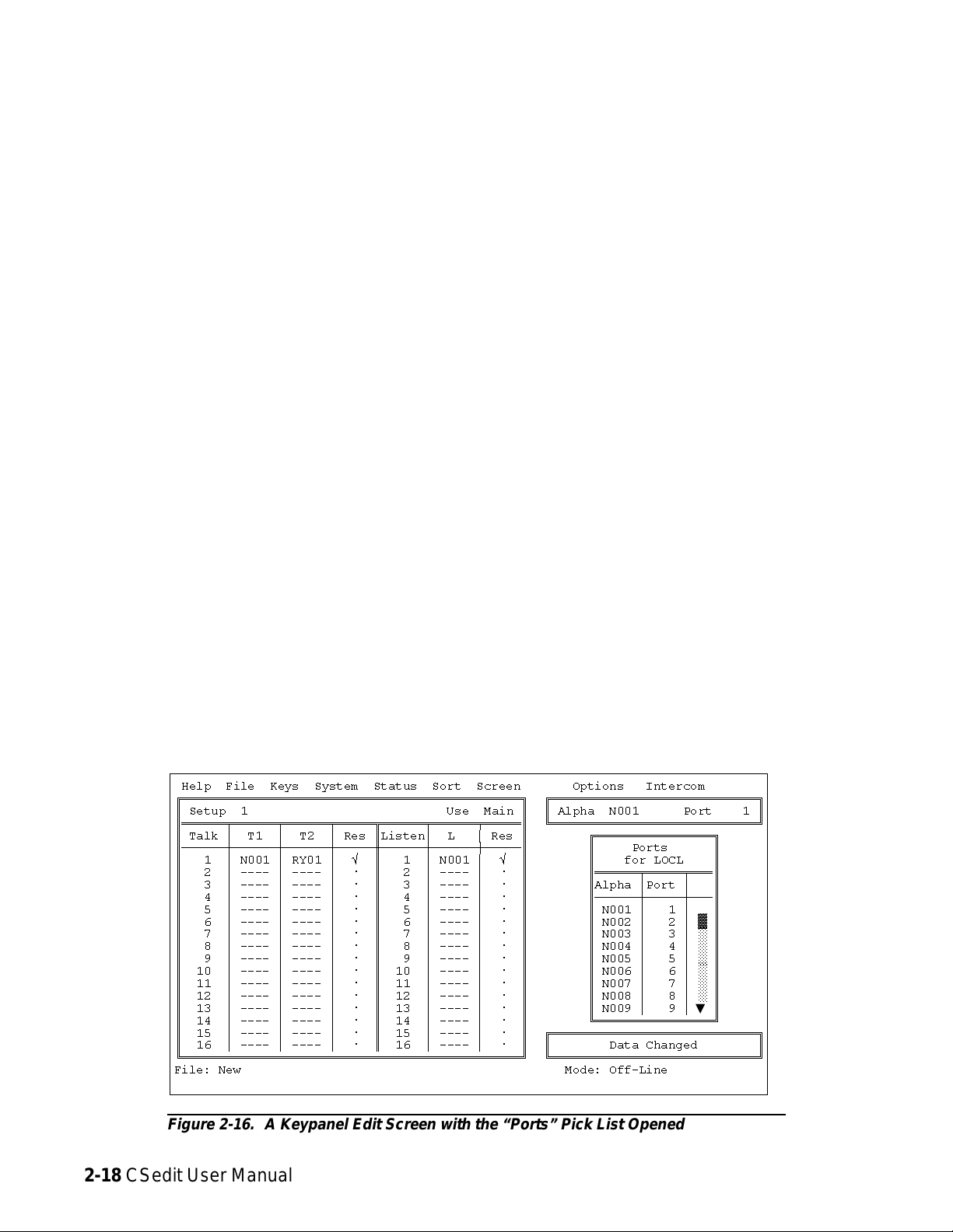
KP-90 and EKP-90 series keypanels and expansion
panels with 8 keys: The leftmost key on any of these pan-
els corresponds to key 9 in the setup page, so start programming at key 9 and do not program keys 1-8.
to assign. Click on the desired port, and it should appear
in the Setup table. When you are finished using the ports
pick list, close it by clicking on any selectable item in the
list with the right mouse button.
KP-12 keypanel; EKP-12, EKP-16 and EKP-20 expansion panels: Please refer to the special notes, "Under-
standing How MODS Work", on page 2-22 for further
information.
Keypanel Setup: Using the Pick Lists
The pick lists in the “Select Key Assign Type” window in
(Figure 2-15) can be used to assign any of the available
types of communication (ports, party lines, etc.) to keys.
To choose a pick list, TAB to the Select Key Assign Type
window. Then, use the UP/DOWN CURSOR keys to
highlight the desired communication type, and press ENTER. (Or simply click on the desired communication type
with a mouse.) For example, if you select “Ports”, the
Ports pick list appears. Figure 2-16 shows the ports pick
list for the local intercom system. You can use the ports
pick list to assign keys for point-to-point communication
as follows:
Without a mouse: Use the CURSOR keys to select the
key in the Setup table that you want to assign. Next, TAB
to the ports pick list, and use the CURSOR keys to select
the port that you want to assign to the key. Press ENTER.
The selected port should appear in the Setup table. When
you are finished using the ports pick list, select it and
press ESCAPE.
With a mouse: Click on the key in the Setup table that
you want to assign, then click on the scroll bar in the
ports pick list to scroll and locate the port that you want
Identifying which Intercom System a Key is
Assigned To (Trunked Intercom Systems)
You can identify which intercom system each key is assigned to by positioning the cursor over the key assignment and then viewing the “Assign” information at the
lower-right corner of the screen. The intercom system
name will be listed first, followed by the Alias name of
the port, party line etc. that is assigned.
Keypanel Setup: Special Functions
Special Functions are available from the Special Functions pick list (Figure 2-17).
The All Call Special Function (AC)
All Call can only be assigned to talk level 1 keys. Activating an All Call key will also activate all talk keys to the
left of the AC key on the keypanel (up to another All Call
key).
Auto-Follow Special Function (AF)
Auto-Follow is assignable to listen keys only. Auto-Follow causes the listen key assignment to always be the
same as the level 1 talk key assignment. Auto-Follow is
the most often-used listen key assignment, because it
saves the operator from having to change the listen key
ÚÄÄÄÄÄÄÄÄÄÄÄÄÄÄÄÄÄÄÄÄÄÄÄÄÄÄÄÄÄÄÄÄÄÄÄÄÄÄÄÄÄÄÄÄÄÄÄÄÄÄÄÄÄÄÄÄÄÄÄÄÄÄÄÄÄÄÄÄÄÄÄÄÄÄÄÄÄÄÄÄ¿
³ Help File Keys System Status Sort Screen Options Intercom ³
³ÉÍÍÍÍÍÍÍÍÍÍÍÍÍÍÍÍÍÍÍÍÍÍÍÍÍÍÍÍÍÍÍÍÍÍÍÍÍÍÍÍÍÍÍÍÍÍ» ÉÍÍÍÍÍÍÍÍÍÍÍÍÍÍÍÍÍÍÍÍÍÍÍÍÍÍÍÍ»³
³º Setup 1 Use Main º º Alpha N001 Port 1 º³
³ºÍÍÍÍÍÍÑÍÍÍÍÍÍÑÍÍÍÍÍÍÑÍÍÍÍÍËÍÍÍÍÍÍÑÍÍÍÍÍÍÑÍÍÍÍͺ ÈÍÍÍÍÍÍÍÍÍÍÍÍÍÍÍÍÍÍÍÍÍÍÍÍÍÍÍͼ³
³º Talk ³ T1 ³ T2 ³ Res ºListen³ L ³ Res º ÉÍÍÍÍÍÍÍÍÍÍÍÍÍÍÍÍ» ³
³ºÄÄÄÄÄÄÅÄÄÄÄÄÄÅÄÄÄÄÄÄÅÄÄÄÄÄ×ÄÄÄÄÄÄÅÄÄÄÄÄÄÅÄÄÄÄĺ º Ports º ³
³º 1 ³ N001 ³ RY01 ³ û º 1 ³ N001 ³ û º º for LOCL º ³
³º 2 ³ ---- ³ ---- ³ ú º 2 ³ ---- ³ ú º ºÍÍÍÍÍÍÑÍÍÍÍÍÑÍÍͺ ³
³º 3 ³ ---- ³ ---- ³ ú º 3 ³ ---- ³ ú º ºAlpha ³Port ³ º ³
³º 4 ³ ---- ³ ---- ³ ú º 4 ³ ---- ³ ú º ºÄÄÄÄÄÄÅÄÄÄÄÄÅÄÄĺ ³
³º 5 ³ ---- ³ ---- ³ ú º 5 ³ ---- ³ ú º º N001 ³ 1 ³ º ³
³º 6 ³ ---- ³ ---- ³ ú º 6 ³ ---- ³ ú º º N002 ³ 2 ³ ² º ³
³º 7 ³ ---- ³ ---- ³ ú º 7 ³ ---- ³ ú º º N003 ³ 3 ³ ° º ³
³º 8 ³ ---- ³ ---- ³ ú º 8 ³ ---- ³ ú º º N004 ³ 4 ³ ° º ³
³º 9 ³ ---- ³ ---- ³ ú º 9 ³ ---- ³ ú º º N005 ³ 5 ³ ° º ³
³º 10 ³ ---- ³ ---- ³ ú º 10 ³ ---- ³ ú º º N006 ³ 6 ³ ° º ³
³º 11 ³ ---- ³ ---- ³ ú º 11 ³ ---- ³ ú º º N007 ³ 7 ³ ° º ³
³º 12 ³ ---- ³ ---- ³ ú º 12 ³ ---- ³ ú º º N008 ³ 8 ³ ° º ³
³º 13 ³ ---- ³ ---- ³ ú º 13 ³ ---- ³ ú º º N009 ³ 9 ³▼º³
³º 14 ³ ---- ³ ---- ³ ú º 14 ³ ---- ³ ú º ÈÍÍÍÍÍÍÍÍÍÍÍÍÍÍÍͼ ³
³º 15 ³ ---- ³ ---- ³ ú º 15 ³ ---- ³ ú º ÉÍÍÍÍÍÍÍÍÍÍÍÍÍÍÍÍÍÍÍÍÍÍÍÍÍÍÍÍ»³
³º 16 ³ ---- ³ ---- ³ ú º 16 ³ ---- ³ ú º º Data Changed º³
³ÈÍÍÍÍÍÍÍÍÍÍÍÍÍÍÍÍÍÍÍÍÍÍÍÍÍÍÍÍÍÍÍÍÍÍÍÍÍÍÍÍÍÍÍÍÍͼ ÈÍÍÍÍÍÍÍÍÍÍÍÍÍÍÍÍÍÍÍÍÍÍÍÍÍÍÍͼ³
³File: New Mode: Off-Line ³
³ ³
ÀÄÄÄÄÄÄÄÄÄÄÄÄÄÄÄÄÄÄÄÄÄÄÄÄÄÄÄÄÄÄÄÄÄÄÄÄÄÄÄÄÄÄÄÄÄÄÄÄÄÄÄÄÄÄÄÄÄÄÄÄÄÄÄÄÄÄÄÄÄÄÄÄÄÄÄÄÄÄÄÄÙ
Figure 2-16. A Keypanel Edit Screen with the “Ports” Pick List Opened
2-18 CSedit User Manual
Page 30

whenever the talk key is changed (either in CSedit or
from the keypanel).
Note You don’t need to manually enter the AF assign-
ment for every listen key. You can use the
“Copy Screen” and “Paste Screen” features of
CSedit. See "Using Copy Screen and Paste
Screen", at right.
equipped with listen keys to allow listening to devices
which do not have talk-back capability, such as party
lines, belt packs etc. It is also useful to force listening
when it is desirable to have an operator continuously hear
a party line or other source.
Keypanel Setup: Using Copy Screen
and Paste Screen
The Auto Listen Special Function (AL)
This assignment works the same as AF, but the listen key
is automatically engaged when the talk key is pressed.
This is often a good assignment for use with party lines or
individual belt packs and other devices that do not have
data connections to the intercom system, because these devices cannot activate the listen path back to the caller.
You should also use this assignment with the push-button
style KP-12 Keypanel when a talk key is assigned to talk
to a TIF-951 Telephone Interface. Otherwise, the keypanel operator will not be able to hear the dial tones and
incoming audio from the telephone line.
The Auto Mute Special Function (AM)
This assignment is the opposite of AL. It allows the keypanel operator to hear the level 1 talk key assignment
only when the talk key is NOT pressed. Auto Mute is useful for talking to devices which echo back the talkers
voice, as it prevents feedback.
The Auto Reciprocal Special Function (AR)
This assignment forces the keypanel to continuously listen to whatever is assigned to the level 1 talk key assignment. It is commonly used on keypanels which are not
ÚÄÄÄÄÄÄÄÄÄÄÄÄÄÄÄÄÄÄÄÄÄÄÄÄÄÄÄÄÄÄÄÄÄÄÄÄÄÄÄÄÄÄÄÄÄÄÄÄÄÄÄÄÄÄÄÄÄÄÄÄÄÄÄÄÄÄÄÄÄÄÄÄÄÄÄÄÄÄÄÄ¿
³ Help File Keys System Status Sort Screen Options Intercom ³
³ÉÍÍÍÍÍÍÍÍÍÍÍÍÍÍÍÍÍÍÍÍÍÍÍÍÍÍÍÍÍÍÍÍÍÍÍÍÍÍÍÍÍÍÍÍÍÍ» ÉÍÍÍÍÍÍÍÍÍÍÍÍÍÍÍÍÍÍÍÍÍÍÍÍÍÍÍÍ»³
³º Setup 1 Use Main º º Alpha N001 Port 1 º³
³ºÍÍÍÍÍÍÑÍÍÍÍÍÍÑÍÍÍÍÍÍÑÍÍÍÍÍËÍÍÍÍÍÍÑÍÍÍÍÍÍÑÍÍÍÍͺ ÈÍÍÍÍÍÍÍÍÍÍÍÍÍÍÍÍÍÍÍÍÍÍÍÍÍÍÍͼ³
³º Talk ³ T1 ³ T2 ³ Res ºListen³ L ³ Res º ³
³ºÄÄÄÄÄÄÅÄÄÄÄÄÄÅÄÄÄÄÄÄÅÄÄÄÄÄ×ÄÄÄÄÄÄÅÄÄÄÄÄÄÅÄÄÄÄĺ ³
³º 1 ³ CUBI ³ ---- ³ û º 1 ³ AR ³ û º ³
³º 2 ³ ---- ³ ---- ³ ú º 2 ³ ---- ³ ú º ÉÍÍÍÍÍÍÍÍÍÍÍÍÍÍÍÍÍÍÍÍÍ» ³
³º 3 ³ ---- ³ ---- ³ ú º 3 ³ ---- ³ ú º º Special Functions º ³
³º 4 ³ ---- ³ ---- ³ ú º 4 ³ ---- ³ ú º º for LOCL º ³
³º 5 ³ ---- ³ ---- ³ ú º 5 ³ ---- ³ ú º ºÍÍÍÍÍÍÑÍÍÍÍÍÍÍÍÍÍÑÍÍͺ ³
³º 6 ³ ---- ³ ---- ³ ú º 6 ³ ---- ³ ú º ºAlpha ³ SF ³ º ³
³º 7 ³ ---- ³ ---- ³ ú º 7 ³ ---- ³ ú º ºÄÄÄÄÄÄÅÄÄÄÄÄÄÄÄÄÄÅÄÄĺ ³
³º 8 ³ ---- ³ ---- ³ ú º 8 ³ ---- ³ ú º º AC ³ All Call ³ º ³
³º 9 ³ ---- ³ ---- ³ ú º 9 ³ ---- ³ ú º º AF ³ Aut-Flw ³ ² º ³
³º 10 ³ ---- ³ ---- ³ ú º 10 ³ ---- ³ ú º º AL ³ Aut-Lst ³ ² º ³
³º 11 ³ ---- ³ ---- ³ ú º 11 ³ ---- ³ ú º º AM ³ Aut-Mute ³ ² º ³
³º 12 ³ ---- ³ ---- ³ ú º 12 ³ ---- ³ ú º º AR ³ Aut-Recp ³ ² º ³
³º 13 ³ ---- ³ ---- ³ ú º 13 ³ ---- ³ ú º º ---- ³ No Assgn ³ º ³
³º 14 ³ ---- ³ ---- ³ ú º 14 ³ ---- ³ ú º ÈÍÍÍÍÍÍÍÍÍÍÍÍÍÍÍÍÍÍÍÍͼ ³
³º 15 ³ ---- ³ ---- ³ ú º 15 ³ ---- ³ ú º ÉÍÍÍÍÍÍÍÍÍÍÍÍÍÍÍÍÍÍÍÍÍÍÍÍÍÍÍÍ»³
³º 16 ³ ---- ³ ---- ³ ú º 16 ³ ---- ³ ú º º Data Changed º³
³ÈÍÍÍÍÍÍÍÍÍÍÍÍÍÍÍÍÍÍÍÍÍÍÍÍÍÍÍÍÍÍÍÍÍÍÍÍÍÍÍÍÍÍÍÍÍͼ ÈÍÍÍÍÍÍÍÍÍÍÍÍÍÍÍÍÍÍÍÍÍÍÍÍÍÍÍͼ³
³File: New Mode: Off-Line ³
³ Assign: LOCL ---- ³
ÀÄÄÄÄÄÄÄÄÄÄÄÄÄÄÄÄÄÄÄÄÄÄÄÄÄÄÄÄÄÄÄÄÄÄÄÄÄÄÄÄÄÄÄÄÄÄÄÄÄÄÄÄÄÄÄÄÄÄÄÄÄÄÄÄÄÄÄÄÄÄÄÄÄÄÄÄÄÄÄÄÙ
Copy Screen and Paste Screen let you copy one keypanel
setup to another location. Copy Screen and Paste Screen
are convenient, for example, if you want to quickly program all listen keys with the Auto-Follow function assignment prior to configuring your keypanel talk keys. You
can do this by programming all the listen keys on one keypanel for Auto-Follow, and then copying that keypanel to
all other keypanels as follows:
1. Begin your first keypanel setup by programming the
Auto-Follow function to all four pages of listen keys
on the keypanel.
2. Before programming anything else, press the F7 key to
access the Screen menu (or click on the Screen menu
with a mouse). The Screen menu will open within the
keypanel setup screen (Figure 2-18).
3. Select “Copy Screen” from the Screen menu. CSedit
will copy the entire keypanel setup (which should
consist only of the auto-follow key assignments).
This copy will be retained for the duration of the edit
session or until you select “Copy Screen” again.
4. Finish your first keypanel setup. When you start on
your next keypanel setup, press F7 again, but this
time select “Paste Screen”. The Auto-Follow special
Figure 2-17. The Keypanel Special Functions Pick List
CSedit User Manual 2-19
Page 31

function will be copied to all four pages of the current keypanel setup. Continue using “Paste Screen”
whenever you start a new keypanel setup.
Note Copy Screen and Paste Screen can also be used
to relocate a keypanel configuration to a new
port. However, a few other steps are also required if you ever need to do this. For further information, see "Using Search", page 3-2.
Keypanel Setup: Port Information
Port information, such as restrictions, trunking priorities
etc. can be accessed by opening the port information win-
ÚÄÄÄÄÄÄÄÄÄÄÄÄÄÄÄÄÄÄÄÄÄÄÄÄÄÄÄÄÄÄÄÄÄÄÄÄÄÄÄÄÄÄÄÄÄÄÄÄÄÄÄÄÄÄÄÄÄÄÄÄÄÄÄÄÄÄÄÄÄÄÄÄÄÄÄÄÄÄÄÄ¿
³ Help File Keys System Status Sort Screen Options Intercom ³
³ÉÍÍÍÍÍÍÍÍÍÍÍÍÍÍÍÍÍÍÍÍÍÍÍÍÍÍÍÍÍÍÍÍÍÍÍÍÍÍÍÚÄÄÄÄÄÄÄÄÄÄÄÄÄÄÄÄÄÄÄÄÄÄÄÄ¿ÍÍÍÍÍÍÍÍÍÍÍÍÍ»³
³º Setup 4 Use³ Cancel Screen Chgs ³ Port 1 º³
³ºÍÍÍÍÍÍÑÍÍÍÍÍÍÑÍÍÍÍÍÍÑÍÍÍÍÍËÍÍÍÍÍÍÑÍÍÍÍͳ ÄÄÄÄÄÄÄÄÄÄÄÄÄÄÄÄÄÄÄÄÄÄ ³ÍÍÍÍÍÍÍÍÍÍÍÍͼ³
³º Talk ³ T1 ³ T2 ³ Res ºListen³ L ³ Paste Screen ³ ³
³ºÄÄÄÄÄÄÅÄÄÄÄÄÄÅÄÄÄÄÄÄÅÄÄÄÄÄ×ÄÄÄÄÄÄÅÄÄÄÄij Copy Screen ³ ³
³º 1 ³ ---- ³ ---- ³ ú º 1 ³ AF ³ ÄÄÄÄÄÄÄÄÄÄÄÄÄÄÄÄÄÄÄÄÄÄ ³ÍÍÍÍÍÍÍÍÍ» ³
³º 2 ³ ---- ³ ---- ³ ú º 2 ³ AF ³ Set Screen Chg Flags ³nctions º ³
³º 3 ³ ---- ³ ---- ³ ú º 3 ³ AF ³ Clear Screen Chg Flags ³CL º ³
³º 4 ³ ---- ³ ---- ³ ú º 4 ³ AF ÀÄÄÄÄÄÄÄÄÄÄÄÄÄÄÄÄÄÄÄÄÄÄÄÄÙÍÍÍÍÍÑÍÍͺ ³
³º 5 ³ ---- ³ ---- ³ ú º 5 ³ AF ³ ú º ºAlpha ³ SF ³ º ³
³º 6 ³ ---- ³ ---- ³ ú º 6 ³ AF ³ ú º ºÄÄÄÄÄÄÅÄÄÄÄÄÄÄÄÄÄÅÄÄĺ ³
³º 7 ³ ---- ³ ---- ³ ú º 7 ³ AF ³ ú º º AC ³ All Call ³ º ³
³º 8 ³ ---- ³ ---- ³ ú º 8 ³ AF ³ ú º º AF ³ Aut-Flw ³ ² º ³
³º 9 ³ ---- ³ ---- ³ ú º 9 ³ AF ³ ú º º AL ³ Aut-Lst ³ ² º ³
³º 10 ³ ---- ³ ---- ³ ú º 10 ³ AF ³ ú º º AM ³ Aut-Mute ³ ² º ³
³º 11 ³ ---- ³ ---- ³ ú º 11 ³ AF ³ ú º º AR ³ Aut-Recp ³ ² º ³
³º 12 ³ ---- ³ ---- ³ ú º 12 ³ AF ³ ú º º ---- ³ No Assgn ³ º ³
³º 13 ³ ---- ³ ---- ³ ú º 13 ³ AF ³ ú º ÈÍÍÍÍÍÍÍÍÍÍÍÍÍÍÍÍÍÍÍÍͼ ³
³º14³----³----³úº14³AF ³úº ³
³º 15 ³ ---- ³ ---- ³ ú º 15 ³ AF ³ ú º ÉÍÍÍÍÍÍÍÍÍÍÍÍÍÍÍÍÍÍÍÍÍÍÍÍÍÍÍÍ»³
³º 16 ³ ---- ³ ---- ³ ú º 16 ³ AF ³ ú º º Data Changed º³
³ÈÍÍÍÍÍÍÍÍÍÍÍÍÍÍÍÍÍÍÍÍÍÍÍÍÍÍÍÍÍÍÍÍÍÍÍÍÍÍÍÍÍÍÍÍÍͼ ÈÍÍÍÍÍÍÍÍÍÍÍÍÍÍÍÍÍÍÍÍÍÍÍÍÍÍÍͼ³
³File: New Mode: Off-Line ³
³ ³
ÀÄÄÄÄÄÄÄÄÄÄÄÄÄÄÄÄÄÄÄÄÄÄÄÄÄÄÄÄÄÄÄÄÄÄÄÄÄÄÄÄÄÄÄÄÄÄÄÄÄÄÄÄÄÄÄÄÄÄÄÄÄÄÄÄÄÄÄÄÄÄÄÄÄÄÄÄÄÄÄÄÙ
dow at the upper-right side of the keypanel edit screen
(Figure 2-19).
Port Restrictions
Use the cursor keys or the mouse to select the desired restriction, then use the SPACE BAR or click with the
mouse to insert or remove a check mark:
Port Access Restricted: A check mark here prevents keypanel operators in the local intercom from assigning this
keypanel to keys from their keypanels.
Figure 2-18. Copying a Key Assignment Screen
ÚÄÄÄÄÄÄÄÄÄÄÄÄÄÄÄÄÄÄÄÄÄÄÄÄÄÄÄÄÄÄÄÄÄÄÄÄÄÄÄÄÄÄÄÄÄÄÄÄÄÄÄÄÄÄÄÄÄÄÄÄÄÄÄÄÄÄÄÄÄÄÄÄÄÄÄÄÄÄÄÄ¿
³ Help File Keys System Status Sort Screen Options Intercom ³
³ÉÍÍÍÍÍÍÍÍÍÍÍÍÍÍÍÍÍÍÍÍÍÍÍÍÍÍÍÍÍÍÍÍÍÍÍÍÍÍÍÍÍÍÍÍÍÍ» ÉÍÍÍÍÍÍÍÍÍÍÍÍÍÍÍÍÍÍÍÍÍÍÍÍÍÍÍÍ»³
³º Setup 1 Use Main º º Alpha VTR1 Port 1 º³
³ºÍÍÍÍÍÍÑÍÍÍÍÍÍÑÍÍÍÍÍÍÑÍÍÍÍÍËÍÍÍÍÍÍÑÍÍÍÍÍÍÑÍÍÍÍͺ º º³
³º Talk ³ T1 ³ T2 ³ Res ºListen³ L ³ Res º º Port Access Restricted ú º³
³ºÄÄÄÄÄÄÅÄÄÄÄÄÄÅÄÄÄÄÄÄÅÄÄÄÄÄ×ÄÄÄÄÄÄÅÄÄÄÄÄÄÅÄÄÄÄĺ º Univ Scroll Restricted û º³
³º 1 ³ CUBI ³ ---- ³ û º 1 ³ AR ³ ú º º CSedit Scroll Restricted ú º³
³º 2 ³ ---- ³ ---- ³ ú º 2 ³ ---- ³ ú º º Trunking Priority 5 º³
³º 3 ³ ---- ³ ---- ³ ú º 3 ³ ---- ³ ú º º º³
³º 4 ³ ---- ³ ---- ³ ú º 4 ³ ---- ³ ú º º IFB Priority 1 º³
³º 5 ³ ---- ³ ---- ³ ú º 5 ³ ---- ³ ú º º Trunking IFB Priority 1 º³
³º 6 ³ ---- ³ ---- ³ ú º 6 ³ ---- ³ ú º º º³
³º 7 ³ ---- ³ ---- ³ ú º 7 ³ ---- ³ ú º º Tone ú º³
³º 8 ³ ---- ³ ---- ³ ú º 8 ³ ---- ³ ú º º º³
³º 9 ³ ---- ³ ---- ³ ú º 9 ³ ---- ³ ú º º Main Panel Setup 1 º³
³º 10 ³ ---- ³ ---- ³ ú º 10 ³ ---- ³ ú º º Exp1 Panel Setup 2 º³
³º 11 ³ ---- ³ ---- ³ ú º 11 ³ ---- ³ ú º º Exp2 Panel Setup - º³
³º 12 ³ ---- ³ ---- ³ ú º 12 ³ ---- ³ ú º º Exp3 Panel Setup - º³
³º 13 ³ ---- ³ ---- ³ ú º 13 ³ ---- ³ ú º º Setup Restricted ú º³
³º 14 ³ ---- ³ ---- ³ ú º 14 ³ ---- ³ ú º ÈÍÍÍÍÍÍÍÍÍÍÍÍÍÍÍÍÍÍÍÍÍÍÍÍÍÍÍͼ³
³º 15 ³ ---- ³ ---- ³ ú º 15 ³ ---- ³ ú º ÉÍÍÍÍÍÍÍÍÍÍÍÍÍÍÍÍÍÍÍÍÍÍÍÍÍÍÍÍ»³
³º 16 ³ ---- ³ ---- ³ ú º 16 ³ ---- ³ ú º º Data Changed º³
³ÈÍÍÍÍÍÍÍÍÍÍÍÍÍÍÍÍÍÍÍÍÍÍÍÍÍÍÍÍÍÍÍÍÍÍÍÍÍÍÍÍÍÍÍÍÍͼ ÈÍÍÍÍÍÍÍÍÍÍÍÍÍÍÍÍÍÍÍÍÍÍÍÍÍÍÍͼ³
³File: New Mode: Off-Line ³
³ ³
ÀÄÄÄÄÄÄÄÄÄÄÄÄÄÄÄÄÄÄÄÄÄÄÄÄÄÄÄÄÄÄÄÄÄÄÄÄÄÄÄÄÄÄÄÄÄÄÄÄÄÄÄÄÄÄÄÄÄÄÄÄÄÄÄÄÄÄÄÄÄÄÄÄÄÄÄÄÄÄÄÄÙ
Figure 2-19. The Keypanel Port Info Edit Screen
2-20 CSedit User Manual
Page 32

Univ Scroll Restricted: If your intercom system is trunked
with other intercom systems, a check mark here prevents
keypanel operators in other intercom systems from assigning this keypanel to keys from their keypanels.
CSedit Scroll Restricted: A check mark here prevents
CSedit users in other intercom systems from assigning
this keypanel in their intercom systems.
Restricting a Port for use as a Trunking Port
To use a port as a trunking port, all that is required is to
turn on all three port restriction flags as described above.
Setup Page Assignment
Type the page number (1 to 4) that you want to assign. In
the example in Figure 2-19, the main keypanel has been
assigned to use setup page 1 and the first expansion panel
has been assigned to use setup page 2.
Note CSedit will not allow you to assign the same
setup page to two panels. If you wish to use a
page number that is already assigned to another
panel, select the panel which is currently using
that number, and press the SPACE BAR to clear
the number. Then, make your new assignment.
IFB and Trunking Priorities
You can assign a trunking priority level to a keypanel
based on the keypanel operator's relative need for access
to limited trunk lines. The Trunking Priority can be any
number from 1-9. Level 9 overrides all other levels, and
gets first access to trunk lines; level 8 overrides level 7
and lower etc.
You can assign an IFB priority to a keypanel based on the
keypanel operator's relative need to have IFB access.
When two or more keypanels have keys assigned to the
same IFB, this determines who gets to access the IFB in
cases where two or more keypanels are trying to access it
at the same time. Level 3 overrides all keypanels with a
level 2 or 1 priority. Level 2 overrides all keypanels with
a level 1 priority. If any keypanel operators with a lower
priority attempt to talk to the IFB while a higher priority
operator is talking, they will not be able to do so. If two
keypanels with the same priority level access an IFB at
the same time, however, both will be heard. The IFB priority can be set separately for the local intercom and for
external intercoms.
Tone Oscillator
Note EKP-20 Expansion Panels. When you assign an
EKP-20 to a setup page, it will occupy key assignments on that page and the next setup page.
For example, it you assign an EKP-20 to setup
page 2, it will occupy keys 1-16 of setup page 2
and keys 1-4 of setup page 3. If you then assign
a second EKP-20 to setup page 3, it will occupy
the remaining keys on setup page 3 and then the
first 8 keys of setup page 4. You can then assign
a third EKP-20 to setup page 4, but only the first
12 keys will operate.
To prevent the keypanel user from reassigning setup
pages from the keypanel, use the SPACE BAR (or click
with a mouse) to place a check mark next to “Setup Restricted”.
Keypanel Setup: Data Changed Window
Any time you make a change to any item in the keypanel
edit screen, a check markûwill be set for that item in the
“Data Changed” window. This check mark is a change
flag. (See the change flag description on page 1-4 for further details.)
Selecting “Tone” and pressing the SPACE BAR (or clicking on "Tone" with a mouse) will turn the tone generator
in the keypanel on or off. (In order for this change to take
effect, you must send the change to the intercom system
using the Activate Chgs command in the Intercom menu.)
You can use this, for example, to check the talk path from
a remotely located keypanel back to the ADAM frame
and to a test keypanel: activate the tone generator, then
force the crosspoint (page 3-16) from the remote keypanel to the test keypanel. You should be able to hear the
tone at the test keypanel. If you turn the tone oscillator on
in CSedit, you will not be able to deactivate it from the
keypanel, so remember to turn it off when finished testing
by pressing the SPACE BAR again or clicking with a
mouse. Again, you must send the change to the intercom
system in order to deactivate the tone oscillator.
CSedit User Manual 2-21
Page 33

Understanding How MODS Work
The KP-12 keypanel and the EKP-12, EKP-16 and EKP-20
expansion panels use a system of "key groups". Key
groups are simply groups of 4 consecutive keys (and their
associated displays) starting with the first key at the left
on the front of the panel. Thus, keys 1-4 form a key
group, as do keys 5-8 and so forth. Each key group is assigned a module number (called a "MOD" number). The
factory default MOD number assignments are shown in
Table 2-1. Any MOD number can be assigned to any
group of four keys. (However, MOD4 should always be
assigned to the SELECT control on the KP-12.) Notice
that all expansion panels are shipped with default MOD
assignments starting at MOD5. If two or three expansion
panels are used along with the KP-12, the module numbers must be reassigned on the second and third expansion panels.
Although MOD numbers can be reassigned, there is an exact relationship between CSedit setup page usage and specific MOD numbers. This relationship is shown in Table
2-2.
With the KP-90 series keypanels, the terminology
"Main", "Exp1" etc. represents actual hardware panels.
This is not the case for the KP-12, EKP-12, EKP-16, and
EKP-20. This is because the MOD numbers can be assigned to any group of 4 keys on any panel. There are two
things to keep in mind though:
Table 2-1. Default Module Number Assignments
for the KP-12, EKP-12, EKP-16 and
EKP-20
KP-12 Default MOD Assignments
MOD1 Keys 1-4
MOD2 Keys 5-8
MOD3 Keys 9-12
MOD4 Keys 13-16 (This MOD should always be
assigned to the SELECT control on the
KP-12. Keys 13-15 are not used. Key 16
corresponds to the SELECT control and is
always used for call waiting.)
EKP-12 Default MOD Assignments
MOD5 Keys 17-20
MOD6 Keys 21-24
MOD7 Keys 25-28
EKP-16 Default MOD Assignments
MOD5 Keys 17-20
MOD6 Keys 21-24
MOD7 Keys 25-28
MOD8 Keys 29-32
EKP-20 Default MOD Assignments
MOD5 Keys 17-20
MOD6 Keys 21-24
MOD7 Keys 25-28
MOD8 Keys 29-32
MOD9 Keys 33-36
1. The KP-12 must always be assigned as "Use Main" in
CSedit, and MOD 4 should always be kept as keys
13-16 of the main keypanel.
2. The remaining setup pages must be assigned as "Exp1",
"Exp2" etc. in order to use the keys that are contained on those pages.
Example 1: If an EKP-20 is connected along with a KP12, and the default MOD settings are used, you must
assign both Exp1 AND Exp2 to setup pages in
CSedit. This is because MOD's 5-8 of the EKP-20
correspond to keys 17-32 of Exp1, while MOD9 of
the EKP-20 corresponds to keys 33-36 of Exp2.
Example 2: If two EKP-20's are connected along with a
KP-12, you must reassign all of the key groups on
one of the EKP-20's to MOD numbers 10-13. (For instructions about how to reassign MOD's, see "SERVICE Menu, MOD ASGN" in the KP-12 User
Manual".) By reassigning the MOD numbers, you
will cause the keys to be reassigned as keys 37-52).
After you have reassigned the MOD's, you must assign Exp1, Exp2 AND Exp3 to setup pages in CSedit.
Table 2-2. The relationship between CSedit
setup pages and the MOD's
CSedit Use: Main
Keys 1-4 MOD1
Keys 5-8 MOD2
Keys 9-12 MOD3
Keys 13-16 MOD4
CSedit Use: Exp1
Keys 17-20 MOD5
Keys 21-24 MOD6
Keys 25-28 MOD7
Keys 29-32 MOD8
CSedit Use: Exp2
Keys 33-36 MOD9
Keys 37-40 MOD10
Keys 41-44 MOD11
Keys 45-48 MOD12
CSedit Use: Exp3
Keys 49-52 MOD13
Keys 53-56 MOD14
Keys 57-60 MOD15
Keys 61-64 MOD16
2-22 CSedit User Manual
Page 34

Section 3: Reference
Table 3-1. CSEDIT.SET File Line Usage
Introduction
This section contains information about additional CSedit
features which may be of interest to some users.
Changing Screen Colors
There are several reasons why you may wish to change
the default screen colors for CSedit:
• You may have a laptop computer which maps col-
ors to shades of grey, and the screen is unreadable
when running CSedit.
• You may have more than one intercom system,
and you wish to distinguish which one you are
working with by the screen colors.
• You may prefer different color choices.
Here is how to change the screen colors:
1. Using a DOS text editor, open the CSEDIT.SET file (located in the CSedit directory).
Note If there is no CSEDIT.SET file, you can create
one by running CSedit and temporarily changing
the com port or baud rate setting as described under "Options, Communications" on page 3-6.
When you exit the Options menu, CSedit will
create the CSEDIT.SET file in the CSedit directory. Restore the original setting, then exit
CSedit and open the new file in your text editor.
2. The CSEDIT.SET file contains 28 lines. The default values for each line are shown in Table 3-1. Lines 1-3
each contain one number, and the available options
are listed in the “Settings” column of the table. Lines
4-28 each contain three numbers (in hex code) separated by single spaces. The first two numbers (foreground and background color) are used when line 3 is
set to "0" (Automatic).The last number is used when
line 3 is set to "1" (Force Mono). The colors that correspond to each numeric value are listed in Table 3-2.
Change the values in each line of the CSEDIT.SET
file to create the color scheme that you want.
3. After you have created the desired color scheme, save
the CSEDIT.SET file as a plain ASCII file.
4. Run CSedit and check the color scheme.
Line Use Settings
1 Baud rate
2 Communications port
3 Color/mono select
Lines 4 - 7 set the colors in the menus:
4 Unselected menu items
5 Selected menu item 7 1 0f
6 Menu Bar e 3 70
7 Unselectable menu item 9 3 70
Lines 8 and 9 set the colors in the error messages:
8 Error message
9 Error message border f c f7
Lines 10 - 20 set the colors in the editing windows:
10 Regular field, edit window
Selectable field, edit
11
window
Background (non field),
12
edit window
13 Border, current window f 1 0f
Border, non-current
14
window
Selectable field,
15
non-current window
16 Restricted field c 1 07
17 Selected restricted 4 3 07
18 Non-editable field a1 07
19 Invalid field e 1 07
20 Selectable invalid field e 3 07
Lines 21 - 24 set the colors for the overall screen:
21 File/on-line status line
22 Bottom status line 7 1 07
23 Background 1 1 07
24 Background selected field 1 1 07
Lines 25 - 28 set the colors in the help screens:
25 Help background
26 Help key words e 1 0f
27 Help selected key word e 3 70
28 Help border 7 1 07
* The Screen menu, for example, when no edit screen is open.
0=9600,
1=38.4k,
2=19.2k
0=COM1,
1=COM2
0=Automatic,
1=Force Mono
See Table 3-2
See Table 3-2
See Table 3-2
See Table 3-2
See Table 3-2
Default
Value
0
0
0
1 3 70
f 4 07
f 1 0f
f 3 70
7 1 07
2 1 07
f 3 70
1 3 70
7 1 07
CSedit User Manual 3-1
Page 35

Table 3-2. Color Chart
Copying and Pasting Edit Screens
Foreground
Color (First
Number)
0=black 0=black 07=normal
1=blue 1=blue 70=reverse
2=green 2=green 0f=bold
3=cyan 3=cyan f7=blinking
4=red 4=red 01=underline
5=magenta 5=magenta 09=bold underline
6=brown 6=brown f1=blinkunderline
7=white 7=white f0=blink reverse
8=dark grey 8=black, blinking
9=light blue 9=blue, blinking
a=light green a=green, blinking
b=light cyan b=cyan,blinking
c=light red c=red, blinking
d=light magenta d=magenta, blinking
e=light yellow e=brown, blinking
f=bright white f=white, blinking
Example: 5 1 70 = magenta foreground and blue background
for color (Automatic) operation; reverse video for monochrome
(Force Mono) operation.
Background Color
(Second Number)
Monochrome
Setting (Third
Number)
Any information that you have configured in one edit
screen may be copied and pasted to another edit screen of
the same type. To copy and paste a screen, proceed as follows:
1. Open the edit screen for the keypanel, party line etc.
that you want to copy.
2. Press the F7 key to open the Screen menu. (Or click on
the Screen menu with a mouse.)
3. Select “Copy Screen” and press the ENTER key. (Or
click on “Copy Screen” with a mouse.) This will
copy the entire current edit screen configuration including all settings in all windows.
4. Close the current edit screen and open the edit screen
that you want to paste to.
5. Press the F7 key, select “Paste Screen” and press the
ENTER key. (Or click on the Screen menu and select
“Paste Screen” with a mouse.) The entire configuration that you copied should now appear in the new
edit screen. You may continue pasting the same configuration to other edit screens of the same type as
long as you do not copy another edit screen.
CSedit Files
The following files are uncompressed and placed on your
hard drive when you run install:
$$STALL.EXE
INSTALL.BAT
CONVERT.EXE
CONVERT.TXT
CONVPROT.EX_
CONVREAL.EXE
UNCO NV.EX_
README.TXT Start-upnotes for CSedit.
CSEDIT.EXE The CSedit program.
CSEDIT.HLP
In addition, any time you change any settings on the Options menu, CSedit creates a file called CSEDIT.SET in
the directory where CSEDIT.EXE is located.
Used to install CSedit on your hard
drive
Used to convert configuration files
from a previous version of CSedit to
the current version. To use the
convert program, type convert at the
DOS prompt, then press the ENTER
key. The convert program converts
all previous versions of intercom
configuration files to version 7
configuration files.
The CSedit help file. (Must be
located in the same directory as
CSEDIT.EXE.)
Using Search (Keys Menu)
Search is used to locate all keypanels that have keys assigned to a specific port (or party line, IFB etc). Search is
useful when you wish to move a user (keypanel, belt pack
etc) to a new location, because you will have to find and
reassign all the keys that communicate with that user. See
"Moving a User to a New Port", below.
Moving a User to a New Port
Any time you relocate an intercom user, whether a keypanel, belt pack etc. to another location, you must reassign all keys throughout the intercom system that are
assigned to talk or listen to that user. This may seem like
a large task, but the search feature makes it very easy.
Note Whenever you relocate a user, we recommend
that you save a backup copy of your configuration file before proceeding. Moving users and reassigning their keys can sometimes have
unforeseen results, and you may want to recall
the old file.
Example: Suppose that you want to move a user called
1DIR (director 1) from a keypanel connected at port
3-2 CSedit User Manual
Page 36

number1toakeypanelconnected at portnumber20.For
theexample,assumethatkeypanelswiththefollowingalphanameshavekeys assigned totalktodirector1:
1AUD,1TD,1VID, 1VTR.Inorder toproperlyupdate
theintercomsystem, usethefollowingprocedure:
1. Update all keypanels with keys assigned to 1DIR to reflect the director’s new location as follows:
a. From the Keys menu, select "Search" and press EN-
TER. If your system is trunked, a matrix pick list
screen will first appear (Figure 3-1). When you
select a matrix to search, a pick list similar to Figure 3-2 will appear.
ÚÄÄÄÄÄÄÄÄÄÄÄÄÄÄÄÄÄÄÄÄÄÄÄÄÄÄÄÄÄÄÄÄÄÄÄÄÄÄÄÄÄÄÄÄÄÄÄÄÄÄÄÄÄÄÄÄÄÄÄÄÄÄÄÄÄÄÄÄÄÄÄÄÄÄÄÄÄÄÄÄ¿
³ Help File Keys System Status Sort Screen Options Intercom ³
³ ÉÍÍÍÍÍÍÍÍÍÍÍÍÍÍÍÍÍÍÍÍ» ³
³ º Target Assignment º ³
³ º ---- º ³
³ ÈÍÍÍÍÍÍÍÍÍÍÍÍÍÍÍÍÍÍÍͼ ³
³ ³
³ ÚÄÄÄÄÄÄÄÄÄÄÄÄÄÄÄÄÄÄÄÄÄÄÄÄÄÄÄÄ¿³
³ ³Select Target Assign Matrix ³³
³ ³ÄÄÄÄÄÄÄÄÄÄÄÄÄÄÄÄÄÄÄÄÄÄÄÄÂÄÄij³
³ ³ LOCL ³ ³³
³ ³ NEWS ³ ² ³³
³ ³8H ³²³³
³ ³8G ³²³³
³ ³6A ³²³³
³ ³ WNBC ³ ² ³³
³ ³ WASH ³ ² ³³
³ ³ CNBC ³ ³³
³ ÀÄÄÄÄÄÄÄÄÄÄÄÄÄÄÄÄÄÄÄÄÄÄÄÄÄÄÄÄÙ³
³ ³
³ ³
³ ³
³ ³
³ ³
³File: On-Line Mode: Off-Line ³
³ ³
ÀÄÄÄÄÄÄÄÄÄÄÄÄÄÄÄÄÄÄÄÄÄÄÄÄÄÄÄÄÄÄÄÄÄÄÄÄÄÄÄÄÄÄÄÄÄÄÄÄÄÄÄÄÄÄÄÄÄÄÄÄÄÄÄÄÄÄÄÄÄÄÄÄÄÄÄÄÄÄÄÄÙ
If your intercom system is not trunked, the search
pick list screen for the local matrix will immediately appear (Figure 3-2).
b. TAB to the Target Assignment window at the up-
per-right of the pick list screen (or move the
mouse cursor over the window) and type in the
name “1DIR”. Press the ENTER key, or click on
1DIR with a mouse, to start the search. (Alternatively, you could select 1DIR from the “Ports”
pick list at the lower-right of the screen.) The
search will result in a pick list of all keypanels
with keys assigned to 1DIR (Figure 3-3).
Figure 3-1. Trunking Intercom Matrix Pick List
ÚÄÄÄÄÄÄÄÄÄÄÄÄÄÄÄÄÄÄÄÄÄÄÄÄÄÄÄÄÄÄÄÄÄÄÄÄÄÄÄÄÄÄÄÄÄÄÄÄÄÄÄÄÄÄÄÄÄÄÄÄÄÄÄÄÄÄÄÄÄÄÄÄÄÄÄÄÄÄÄÄ¿
³ Help File Keys System Status Sort Screen Options Intercom ³
³ ÉÍÍÍÍÍÍÍÍÍÍÍÍÍÍÍÍÍÍÍÍ» ³
³ º Target Assignment º ³
³ º 1DIR º ³
³ ÈÍÍÍÍÍÍÍÍÍÍÍÍÍÍÍÍÍÍÍͼ ³
³ ³
³ ÚÄÄÄÄÄÄÄÄÄÄÄÄÄÄÄÄÄÄÄÄÄÄÄÄÄÄÄÄ¿³
³ ³ Select Target Assign Type ³³
³ ³ for Matrix LOCL ³³
³ ³ÄÄÄÄÄÄÄÄÄÄÄÄÄÄÄÄÄÄÄÄÄÄÄÄÄÄÄij³
³ ³ Ports ³³
³ ³ Party Lines ³³
³ ³ IFBs ³³
³ ³ Special Lists ³³
³ ³ Relays ³³
³ ³ ISOs ³³
³ ³ Special Functions ³³
³ ÀÄÄÄÄÄÄÄÄÄÄÄÄÄÄÄÄÄÄÄÄÄÄÄÄÄÄÄÄÙ³
³ ³
³ ³
³ ³
³ ³
³ ³
³File: On-Line Mode: Off-Line ³
³ ³
ÀÄÄÄÄÄÄÄÄÄÄÄÄÄÄÄÄÄÄÄÄÄÄÄÄÄÄÄÄÄÄÄÄÄÄÄÄÄÄÄÄÄÄÄÄÄÄÄÄÄÄÄÄÄÄÄÄÄÄÄÄÄÄÄÄÄÄÄÄÄÄÄÄÄÄÄÄÄÄÄÄÙ
Figure 3-2. Typical Matrix Pick List (Local Matrix Shown)
CSedit User Manual 3-3
Page 37

c. Use the cursor keys to select the first port in the
search pick list (1AUD), and press the ENTER
key. Or, click on 1AUD with a mouse. The keypanel edit screen for that port should appear, and
the key assigned to 1DIR should be highlighted
(Figure 3-4).
port's name into the setup table in place of
"1DIR".)
e. Press the ESCAPE key (or click on any selectable
item with the right mouse button) to return to the
search pick list (Figure 3-3).
d. Type in the alpha name that is currently being used
for port number 20. (Hint: If you do not know
the name that is assigned to a port, TAB to the
"Select Key Assign Type" window, select
"Ports" and press ENTER. Then scroll to the desired port number. Press ENTER to insert that
ÚÄÄÄÄÄÄÄÄÄÄÄÄÄÄÄÄÄÄÄÄÄÄÄÄÄÄÄÄÄÄÄÄÄÄÄÄÄÄÄÄÄÄÄÄÄÄÄÄÄÄÄÄÄÄÄÄÄÄÄÄÄÄÄÄÄÄÄÄÄÄÄÄÄÄÄÄÄÄÄÄ¿
³ Help File Keys System Status Sort Screen Options Intercom ³
³ ÉÍÍÍÍÍÍÍÍÍÍÍÍÍÍÍÍÍÍÍÍÍÍÍÍÍÍÍÍ»³
³ º Alpha 1AUD Port 4 º³
³ ÈÍÍÍÍÍÍÍÍÍÍÍÍÍÍÍÍÍÍÍÍÍÍÍÍÍÍÍͼ³
³ ³
³ ³
³ ³
³ ³
³ ³
³ ÉÍÍÍÍÍÍÍÍÍÍÍÍÍÍÍÍ» ³
³ ºAlpha ³Port ³ º ³
³ ºÄÄÄÄÄÄÅÄÄÄÄÄÅÄÄĺ ³
³ º 1AUD ³ 4 ³ º ³
³ º1TD ³ 2³°º ³
³ º 1VID ³ 3 ³ ° º ³
³ º 1VTR ³ 5 ³ ° º ³
³ ÈÍÍÍÍÍÍÍÍÍÍÍÍÍÍÍͼ ³
³ ³
³ ³
³ ³
³ ³
³ ³
³ ³
³File: On-Line Mode: Off-Line ³
³ ³
ÀÄÄÄÄÄÄÄÄÄÄÄÄÄÄÄÄÄÄÄÄÄÄÄÄÄÄÄÄÄÄÄÄÄÄÄÄÄÄÄÄÄÄÄÄÄÄÄÄÄÄÄÄÄÄÄÄÄÄÄÄÄÄÄÄÄÄÄÄÄÄÄÄÄÄÄÄÄÄÄÄÙ
f. Select each port in succession and repeat steps c, d
and e.
g. When all ports in the search pick list have been
changed, press the ESCAPE key as needed to return to the menu bar.
Figure 3-3. The Search Pick List
ÚÄÄÄÄÄÄÄÄÄÄÄÄÄÄÄÄÄÄÄÄÄÄÄÄÄÄÄÄÄÄÄÄÄÄÄÄÄÄÄÄÄÄÄÄÄÄÄÄÄÄÄÄÄÄÄÄÄÄÄÄÄÄÄÄÄÄÄÄÄÄÄÄÄÄÄÄÄÄÄÄ¿
³ Help File Keys System Status Sort Screen Options Intercom ³
³ÉÍÍÍÍÍÍÍÍÍÍÍÍÍÍÍÍÍÍÍÍÍÍÍÍÍÍÍÍÍÍÍÍÍÍÍÍÍÍÍÍÍÍÍÍÍÍ» ÉÍÍÍÍÍÍÍÍÍÍÍÍÍÍÍÍÍÍÍÍÍÍÍÍÍÍÍÍ»³
³º Setup 1 Use Main º º Alpha N001 Port 1 º³
³ºÍÍÍÍÍÍÑÍÍÍÍÍÍÑÍÍÍÍÍÍÑÍÍÍÍÍËÍÍÍÍÍÍÑÍÍÍÍÍÍÑÍÍÍÍͺ ÈÍÍÍÍÍÍÍÍÍÍÍÍÍÍÍÍÍÍÍÍÍÍÍÍÍÍÍͼ³
³º Talk ³ T1 ³ T2 ³ Res ºListen³ L ³ Res º ³
³ºÄÄÄÄÄÄÅÄÄÄÄÄÄÅÄÄÄÄÄÄÅÄÄÄÄÄ×ÄÄÄÄÄÄÅÄÄÄÄÄÄÅÄÄÄÄĺ ³
³º 1 ³ ---- ³ ---- ³ ú º 1 ³ ---- ³ ú º ÚÄÄÄÄÄÄÄÄÄÄÄÄÄÄÄÄÄÄÄÄÄÄÄÄÄÄÄÄ¿³
³º 2 ³ ---- ³ ---- ³ ú º 2 ³ ---- ³ ú º ³ Select Key Assign Type ³³
³º 3 ³ ---- ³ ---- ³ ú º 3 ³ ---- ³ ú º ³ for Matrix LOCL ³³
³º 4 ³ ---- ³ ---- ³ ú º 4 ³ ---- ³ ú º ³ÄÄÄÄÄÄÄÄÄÄÄÄÄÄÄÄÄÄÄÄÄÄÄÄÄÄÄij³
³º 5 ³ ---- ³ ---- ³ ú º 5 ³ ---- ³ ú º ³ Ports ³³
³º 6 ³ ---- ³ ---- ³ ú º 6 ³ ---- ³ ú º ³ Party Lines ³³
³º 7 ³ ---- ³ ---- ³ ú º 7 ³ ---- ³ ú º ³ IFBs ³³
³º 8 ³ ---- ³ ---- ³ ú º 8 ³ ---- ³ ú º ³ Special Lists ³³
³º 9 ³ ---- ³ ---- ³ ú º 9 ³ ---- ³ ú º ³ Relays ³³
³º 10 ³ ---- ³ ---- ³ ú º 10 ³ ---- ³ ú º ³ ISOs ³³
³º 11 ³ ---- ³ ---- ³ ú º 11 ³ ---- ³ ú º ³ Special Functions ³³
³º 12 ³ ---- ³ ---- ³ ú º 12 ³ ---- ³ ú º ÀÄÄÄÄÄÄÄÄÄÄÄÄÄÄÄÄÄÄÄÄÄÄÄÄÄÄÄÄÙ³
³º 13 ³ ---- ³ ---- ³ ú º 13 ³ ---- ³ ú º ³
³º 14 ³ ---- ³ ---- ³ ú º 14 ³ ---- ³ ú º ³
³º 15 ³ ---- ³ ---- ³ ú º 15 ³ ---- ³ ú º ÉÍÍÍÍÍÍÍÍÍÍÍÍÍÍÍÍÍÍÍÍÍÍÍÍÍÍÍÍ»³
³º 16 ³ ---- ³ ---- ³ ú º 16 ³ ---- ³ ú º º Data Changed º³
³ÈÍÍÍÍÍÍÍÍÍÍÍÍÍÍÍÍÍÍÍÍÍÍÍÍÍÍÍÍÍÍÍÍÍÍÍÍÍÍÍÍÍÍÍÍÍͼ ÈÍÍÍÍÍÍÍÍÍÍÍÍÍÍÍÍÍÍÍÍÍÍÍÍÍÍÍͼ³
³File: New Mode: Off-Line ³
³ ³
ÀÄÄÄÄÄÄÄÄÄÄÄÄÄÄÄÄÄÄÄÄÄÄÄÄÄÄÄÄÄÄÄÄÄÄÄÄÄÄÄÄÄÄÄÄÄÄÄÄÄÄÄÄÄÄÄÄÄÄÄÄÄÄÄÄÄÄÄÄÄÄÄÄÄÄÄÄÄÄÄÄÙ
1DIR
Figure 3-4. A Keypanel Edit Screen Opened from the Search Pick List
3-4 CSedit User Manual
Page 38

2. Copy the director’s keypanel configuration from the old
location to the new location. (See "Copying and Pasting Edit Screens", page 3-2, then return here.)
Note: In an actual situation, if there was already a key-
panel setup in use at the new location, you could
use Copy Screen and Paste Screen to save that
setup to some other unused location first.
Options Menu (F9 Key)
The Options menu (Figure 3-5) is used to change settings
for screen colors, baud rate, and COM port usage. For information about the color settings, see "Options, Color",
below. For information about COM port and baud rate settings, see "Options, Communications", page 3-6
3. Update the keypanel alpha names:
a. Open the System menu and select “Port Alphas”.
b. Change the alpha name of the director’s old loca-
tion from "1DIR" to "N001", then change the alpha name of the director’s new location to
"1DIR".
4. Press ESCAPE as needed to return to the menu bar.
5. Save your changes, then send the changes to the intercom system. (Use “Activate Chgs” on the Intercom
menu.) If all steps have been completed correctly, it
should now be possible to communicate with the director at the new location.
ÚÄÄÄÄÄÄÄÄÄÄÄÄÄÄÄÄÄÄÄÄÄÄÄÄÄÄÄÄÄÄÄÄÄÄÄÄÄÄÄÄÄÄÄÄÄÄÄÄÄÄÄÄÄÄÄÄÄÄÄÄÄÄÄÄÄÄÄÄÄÄÄÄÄÄÄÄÄÄÄÄ¿
³ Help File Keys System Status Sort Screen Options Intercom ³
³ ÚÄÄÄÄÄÄÄÄÄÄÄÄÄÄÄÄ¿ ³
³ ³ Color ³ ³
³ ³ Communications ³ ³
³ ÀÄÄÄÄÄÄÄÄÄÄÄÄÄÄÄÄÙ ³
³ ³
³ ³
³ ³
³ ³
³ ³
³ ³
³ ³
³ ³
³ ³
³ ³
³ ³
³ ³
³ ³
³ ³
³ ³
³ ³
³ ³
³ ³
³File: New Mode: Off-Line ³
³ ³
ÀÄÄÄÄÄÄÄÄÄÄÄÄÄÄÄÄÄÄÄÄÄÄÄÄÄÄÄÄÄÄÄÄÄÄÄÄÄÄÄÄÄÄÄÄÄÄÄÄÄÄÄÄÄÄÄÄÄÄÄÄÄÄÄÄÄÄÄÄÄÄÄÄÄÄÄÄÄÄÄÄÙ
Options, Color
When you select “Color” from the Options menu, the
“Color and Mono Setup” screen will appear (Figure 3-6).
Press the SPACE BAR to select “Automatic” for color operation or “Force Mono” for monochrome operation.
“Automatic” detects the presence of a color adapter (CGA,
EGA, VGA) and sets up screen colors for color operation.
“Force Mono” overrides automatic color setup and forces
monochrome (black and white) operation. Force mono is
the correct choice, for example, with many laptop computers that have a monochrome LCD display.
Note Any time you make any change in the Color and
Mono Setup screen and then exit the screen, a
file called CSEDIT.SET is created in the CSedit
directory. You can customize the screen colors
by modifying the CSEDIT.SET file. See "Changing Screen Colors", page 3-1
Figure 3-5. The CSedit Option Menu
CSedit User Manual 3-5
Page 39

IMPORTANT: IF YOU HAVE A CGA MONITOR, OR
A LAPTOP COMPUTER THAT EMULATES CGA.
Do not select “Force Mono” unless you know that your
computer also supports monochrome operation. Most
CGA machines abort when forced to monochrome. If you
select “Force Mono” and the computer aborts, proceed as
follows:
1. Reboot the computer, but do not run CSedit.
Options, Communications
When you select “Communications” from the Options
menu, the Communications Setup screen will appear (Figure 3-7). This menu item is used to set the COM port and
baud rate for communication between the computer and
the intercom system. If the setting is not correct, CSedit
will not be able to get on-line with the intercom system
and the mouse may not work. Check and/or change the
COM port and baud rate settings as follows:
2. Erase the CSEDIT.SET file from the CSedit directory.
3. Run CSedit. The “Automatic” option will be selected as
the default color selection.
NOTE TO LAPTOP COMPUTER USERS
Many LCD laptop computers map color selections to
grey-scale values. There are no standards for this mapping, so on some machines, the standard CSedit color
scheme will not be readable. If this is the case, you may
have to make changes in the CSEDIT.SET file. See
"Changing Screen Colors", page 3-1.
COM Port
1. Select the Com Port setting, then press the SPACE
BAR to select either "COM1" or "COM2".
2. Press the ESCAPE key to return to the menu screen. After a few moments, the message “Uploading data
from intercom” should appear in the lower-left corner of the screen, and “On-line” should appear in the
lower-right corner. If not, the cable from the PC to
the intercom system may be incorrectly wired. See
Appendix A for information about cable wiring.
Note If you are using a mouse, you must exit CSedit and
restart the program to re-initialize the mouse. To
exit,usetheLEFT/RIGHT arrow keys to select
the File menu on the menu bar (or press F2).
Then, use the DOWN arrow key to open the
menu. Select “Exit to DOS”, and press the ENTER key. When you restart CSedit, the mouse
should be operational.
ÚÄÄÄÄÄÄÄÄÄÄÄÄÄÄÄÄÄÄÄÄÄÄÄÄÄÄÄÄÄÄÄÄÄÄÄÄÄÄÄÄÄÄÄÄÄÄÄÄÄÄÄÄÄÄÄÄÄÄÄÄÄÄÄÄÄÄÄÄÄÄÄÄÄÄÄÄÄÄÄÄ¿
³ Help File Keys System Status Sort Screen Options Intercom ³
³ ³
³ ³
³ ³
³ ³
³ ³
³ ³
³ ³
³ ³
³ ÉÍÍÍÍÍÍÍÍÍÍÍÍÍÍÍÍÍÍÍÍÍÍÍÍÍÍÍÍÍÍÍÍÍÍ» ³
³ º Color and Mono Setup º ³
³ ºÍÍÍÍÍÍÍÍÍÍÍÍÍÍÍÍÍÍÍÍÍÍÍÍÍÍÍÍÍÍÍÍÍͺ ³
³º º³
³ º Color/Mono Mode: Automatic º ³
³ ÈÍÍÍÍÍÍÍÍÍÍÍÍÍÍÍÍÍÍÍÍÍÍÍÍÍÍÍÍÍÍÍÍÍͼ ³
³ ³
³ ³
³ ³
³ ³
³ ³
³ ³
³ ³
³ ³
³File: New Mode: Off-Line ³
³ ³
ÀÄÄÄÄÄÄÄÄÄÄÄÄÄÄÄÄÄÄÄÄÄÄÄÄÄÄÄÄÄÄÄÄÄÄÄÄÄÄÄÄÄÄÄÄÄÄÄÄÄÄÄÄÄÄÄÄÄÄÄÄÄÄÄÄÄÄÄÄÄÄÄÄÄÄÄÄÄÄÄÄÙ
Figure 3-6. The Color and Mono Setup Screen
3-6 CSedit User Manual
Page 40

ÚÄÄÄÄÄÄÄÄÄÄÄÄÄÄÄÄÄÄÄÄÄÄÄÄÄÄÄÄÄÄÄÄÄÄÄÄÄÄÄÄÄÄÄÄÄÄÄÄÄÄÄÄÄÄÄÄÄÄÄÄÄÄÄÄÄÄÄÄÄÄÄÄÄÄÄÄÄÄÄÄ¿
³ Help File Keys System Status Sort Screen Options Intercom ³
³ ³
³ ³
³ ³
³ ³
³ ³
³ ³
³ ³
³ ³
³ ÉÍÍÍÍÍÍÍÍÍÍÍÍÍÍÍÍÍÍÍÍÍÍÍÍÍ» ³
³ º Communications Setup º ³
³ ºÍÍÍÍÍÍÍÍÍÍÍÍÍÍÍÍÍÍÍÍÍÍÍÍͺ ³
³ºº ³
³ º Baud Rate: 9600 º ³
³ º Comm Port: COM1 º ³
³ ÈÍÍÍÍÍÍÍÍÍÍÍÍÍÍÍÍÍÍÍÍÍÍÍÍͼ ³
³ ³
³ ³
³ ³
³ ³
³ ³
³ ³
³ ³
³File: New Mode: Off-Line ³
³ ³
ÀÄÄÄÄÄÄÄÄÄÄÄÄÄÄÄÄÄÄÄÄÄÄÄÄÄÄÄÄÄÄÄÄÄÄÄÄÄÄÄÄÄÄÄÄÄÄÄÄÄÄÄÄÄÄÄÄÄÄÄÄÄÄÄÄÄÄÄÄÄÄÄÄÄÄÄÄÄÄÄÄÙ
Figure 3-7. The Communications Setup Screen
Baud Rate
Two baud rates are available: 9600 baud and 38.4K baud.
The default baud rate is 9600 baud. Whichever baud rate
is used, make sure that DIP switch 1 is set correctly on
both the main and backup controller cards in the ADAM
or ADAM CS frame.
Operation at 9600 baud allows the use of a longer cable,
but results in slower communication between the computer and the intercom system. The parameters for operation at 9600 baud are: no parity, 1 stop bit, 8 data bits, 1
start bit, 9600 baud.
38.4K baud results in fastest operation, but requires a
short cable from the computer to the intercom, less than
25 ft (8 m).
CENTRAL CONTROL KEYPANEL
2400 HZ
TONE
INPUT
IF01
MATRIX
IFB OUTPUT INACTIVE
(IFB Key Not
Pressed)
Remote IFB
Remote IFB uses a TIM-940 Tone Activated Switcher and a
2400 Hz tone source as illustrated in Figure 3-8. The 2400
Hz tone source is connected to an audio input port of the matrix. The tone input port and IFB output port are then defined in the IFB edit screen of CSedit (page 2-6). The IFB is
then assigned to a keypanel key.
During normal operation, the audio path from the remote
audio source to the remote listener passes through the TIM940 uninterrupted. When the operator at the central control
keypanel presses the IFB key, the controller’s audio signal,
plus the 2400 Hz signal is routed, via the IFB output, to the
TIM-940. The TIM-940 removes the 2400 Hz tone from the
audio signal and uses this tone to activate the switcher. The
switcher cuts off the remote audio signal, and routes the controller’s audio signal to the remote listener.
CENTRAL CONTROL KEYPANEL
(IFB Key
Pressed)
IF01
2400 HZ
TONE
INPUT
MATRIX
TONE + AUDIO
REMOTE AUDIO SOURCE
REMOTE
AUDIO
TIM-940
REMOTE
AUDIO
LISTENER
NORMAL SIGNAL PATH
Figure 3-8. Remote IFB Operation
REMOTE AUDIO SOURCE
REMOTE
AUDIO
CENTRAL CONTROL
TIM-940
AUDIO
SIGNAL PATH DURING IFB
CSedit User Manual 3-7
LISTENER
Page 41

Screen Menu (F7 Key)
Speed Formatting
The Screen menu is generally selectable only when an
edit screen is currently open (for example a keypanel edit
screen or a party line edit screen).
Screen, Cancel Screen Chg
If editing a file other than the on-line file, selecting “Cancel Screen Chgs” will cause all settings in the currently
opened edit screen to be restored to the settings when the
screen was entered.
If editing the on-line file, selecting “Cancel Screen Chgs”
will cause all changes to the current screen to be cleared,
and the current intercom setup for the screen will be
uploaded from the intercom system.
If editing a force & inhibit table in the System menu, selecting “Cancel Screen Chgs” will cause CSedit to access
the intercom system and get updated information about
what crosspoints are currently closed. Closed crosspoints
will be displayed using check marksû.
If viewing communication error counters in the Status
menu, selecting “Cancel Screen Chgs” will cause the
communication error counters to be cleared.
Screen, Paste Screen
Paste Screen is selectable only after an edit screen has
been copied using Copy Screen. Selecting “Paste Screen”
will cause the copied configuration to be pasted to the current edit screen. All settings for all items in the copied
screen will be pasted.
Screen, Copy Screen
Speed formatting is useful when you want to make several identical key assignments in a column, or when you
wish to quickly erase all the key assignments in a column.
For example, in many intercom systems, the listen keys
are usually programmed to auto-follow the corresponding
talk key. When the talk key is programmed, the listen key
will automatically receive the same assignment. The following example shows how you can rapidly setup all the
listen keys on a keypanel for auto-follow operation.
1. From the Keys menu, select “Ports” and press ENTER.
The keypanel pick list should appear.
2. Select a keypanel from the keypanel pick list and press
ENTER. The keypanel setup screen for that keypanel
should appear.
3. Move the cursor to highlight the “L” column for listen
key 1.
4. Select “Auto-Follow” from the “Special Functions”
pick list at the right side of the screen.
5. Press the “+” key on the computer’s numeric keypad.
“AF” should appear in the “L” column of the key assignment table, and the next line in the table should
be highlighted. Press the UP cursor key to re-select
“AF” and again press the “+” key. If you repeatedly
press the UP cursor key followed by the “+” key, the
“AF” assignment should be inserted in every line of
the key assignment table.
6. To rapidly erase multiple key assignments:
a. Position the cursor in the key assignment table over
the top-most key in a column that you wish to
erase.
Copy Screen will copy the entire configuration for the current edit screen, including the settings for all items in all
windows not currently opened.
Related Topics: "Copying and Pasting Edit Screens", and
"Moving a User to a New Port", page 3-2.
3-8 CSedit User Manual
b. Select the “No Assgn” special function from the
Special Functions pick list.
c. Hold down the “+” key on the numeric keypad.
Key assignments will continue to be erased until
you release the “+” key.
Page 42

Status Menu (F5 Key)
Ok ? Indicates that the device is a keypanel with
an unknown or earlier version of software.
To access all items in this menu, the computer must be
connected to the intercom system, and the on-line file
must be opened in CSedit.
Status, Port
When you select "Port" from the Status menu, the Panel
Configuration table appears (Figure 3-9). Port numbers
(listed under "Panels") and alphas are listed in the leftmost columns. The status of each port is indicated in the
right column as follows:
Bad Off: Indicates that there has never been any data
communication with this port during the current edit session. This could be because the
device is not a keypanel, or is a keypanel
that is not turned on.
Bad Cut: Indicates that there was a data device at the port
at some time during the current edit session, but
it is not now transmitting data.
Ok TIF Indicates that the data device is a telephone
interface.
Ok 1-7 Kp Indicates that the device is a normally func-
tioning keypanel. The number 1-7 indicates
the keypanel DIP switch settings for
switches SW1-1 through SW1-3 on the keypanel rear panel as summarized in the table
below. Refer to the keypanel’s installation
instructions for information on DIP switch
settings.
Number
Displayed
0 Open Open Open
1 Open Closed Open
2 Closed Closed Open
3 Same as number 2
4 Open Open Closed
5 Open Closed Closed
6 Closed Closed Closed
7 Same as number 6
Switch Settings
SW1-1 SW1-2 SW1-3
ÚÄÄÄÄÄÄÄÄÄÄÄÄÄÄÄÄÄÄÄÄÄÄÄÄÄÄÄÄÄÄÄÄÄÄÄÄÄÄÄÄÄÄÄÄÄÄÄÄÄÄÄÄÄÄÄÄÄÄÄÄÄÄÄÄÄÄÄÄÄÄÄÄÄÄÄÄÄÄÄÄ¿
³ Help File Keys System Status Sort Screen Options Intercom ³
³ ³
³ ÉÍÍÍÍÍÍÍÍÍÍÍÍÍÍÍÍÍÍÍÍÍÍÍÍÍÍÍÍÍÍÍ» ³
³ º Panel Configuration º ³
³ ºÍÍÍÍÍÑÍÍÍÍÍÍÍÍÍÍÑÍÍÍÍÍÍÍÍÍÍÑÍÍͺ ³
³ ºPanel³Alpha ³ Config ³ º ³
³ ºÄÄÄÄÄÅÄÄÄÄÄÄÄÄÄÄÅÄÄÄÄÄÄÄÄÄÄÅÄÄĺ ³
³ º 1 ³ N001 ³ Bad Off ³ º ³
³ º 2³N002 ³Bad Off³°º ³
³ º 3³N003 ³Bad Off³²º ³
³ º 4³N004 ³Bad Off³°º ³
³ º 5³N005 ³Bad Off³°º ³
³ º 6³N006 ³Bad Off³°º ³
³ º 7³N007 ³Bad Off³°º ³
³ º 8³N008 ³Bad Off³°º ³
³ º 9³N009 ³Bad Off³°º ³
³ º 10 ³ N010 ³ Bad Off ³ ° º ³
³ º 11 ³ N011 ³ Bad Off ³ ° º ³
³ º 12 ³ N012 ³ Bad Off ³ ° º ³
³ º 13 ³ N013 ³ Bad Off ³ ° º ³
³ º 14 ³ N014 ³ Bad Off ³ ° º ³
³ º 15 ³ N015 ³ Bad Off ³▼º³
³ ÈÍÍÍÍÍÍÍÍÍÍÍÍÍÍÍÍÍÍÍÍÍÍÍÍÍÍÍÍÍÍͼ ³
³File: On-Line Mode: Off-Line ³
³ ³
ÀÄÄÄÄÄÄÄÄÄÄÄÄÄÄÄÄÄÄÄÄÄÄÄÄÄÄÄÄÄÄÄÄÄÄÄÄÄÄÄÄÄÄÄÄÄÄÄÄÄÄÄÄÄÄÄÄÄÄÄÄÄÄÄÄÄÄÄÄÄÄÄÄÄÄÄÄÄÄÄÄÙ
Figure 3-9. The Panel Configuration Table
CSedit User Manual 3-9
Page 43

Status, Standby Controller
This menu item provides information about the current
status of the backup, or standby, master controller card in
the ADAM or ADAM CS frame. When you select this
item, the Standby Master Controller Configuration table
appears (Figure 3-10).
The information displayed in the “Config” column indicates status as follows:
Bad Off: Indicates that there has never been any data
communication with a standby master controller during the current edit session. This
could be because the device is not connected or has not been turned on.
ÚÄÄÄÄÄÄÄÄÄÄÄÄÄÄÄÄÄÄÄÄÄÄÄÄÄÄÄÄÄÄÄÄÄÄÄÄÄÄÄÄÄÄÄÄÄÄÄÄÄÄÄÄÄÄÄÄÄÄÄÄÄÄÄÄÄÄÄÄÄÄÄÄÄÄÄÄÄÄÄÄ¿
³ Help File Keys System Status Sort Screen Options Intercom ³
³ ³
³ ³
³ ³
³ ³
³ ³
³ ³
³ ³
³ ³
³ ÉÍÍÍÍÍÍÍÍÍÍÍÍÍÍÍÍÍÍÍÍÍÍÍÍ» ³
³ º Stby MC Configuration º ³
³ ºÍÍÍÍÍÍÍÍÍÑÍÍÍÍÍÍÍÍÍÍÑÍÍͺ ³
³ º Stby MC ³ Config ³ º ³
³ ºÄÄÄÄÄÄÄÄÄÅÄÄÄÄÄÄÄÄÄÄÅÄÄĺ ³
³ º 1³Bad Off³ º ³
³ ÈÍÍÍÍÍÍÍÍÍÍÍÍÍÍÍÍÍÍÍÍÍÍÍͼ ³
³ ³
³ ³
³ ³
³ ³
³ ³
³ ³
³ ³
³File: On-Line Mode: Off-Line ³
³ ³
ÀÄÄÄÄÄÄÄÄÄÄÄÄÄÄÄÄÄÄÄÄÄÄÄÄÄÄÄÄÄÄÄÄÄÄÄÄÄÄÄÄÄÄÄÄÄÄÄÄÄÄÄÄÄÄÄÄÄÄÄÄÄÄÄÄÄÄÄÄÄÄÄÄÄÄÄÄÄÄÄÄÙ
Ok Cur Indicates that the standby master controller
is connected and operating, and that it has
been updated with the current intercom system configuration.
Ok Old Indicates that the standby master controller
is connected and operating, but that it has
not been updated with the current intercom
system configuration.
Note: If several ADAM frames are interconnected us-
ing Bus Expansion cards, the status is only reported for the standby master controller in frame
number one.
Figure 3-10. The Standby Master Controller Configuration Table
3-10 CSedit User Manual
Page 44

Status, Trunk Master
When you select "Trunk Master" from the Status menu,
the Trunking Master Controller configuration table appears (Figure 3-11).
The information displayed in the “Config” column indicates status as follows:
Bad Off: Indicates that there has never been any data
communication with a trunk master during
the current edit session. This could be because the device is not connected or has not
been turned on.
ÚÄÄÄÄÄÄÄÄÄÄÄÄÄÄÄÄÄÄÄÄÄÄÄÄÄÄÄÄÄÄÄÄÄÄÄÄÄÄÄÄÄÄÄÄÄÄÄÄÄÄÄÄÄÄÄÄÄÄÄÄÄÄÄÄÄÄÄÄÄÄÄÄÄÄÄÄÄÄÄÄ¿
³ Help File Keys System Status Sort Screen Options Intercom ³
³ ³
³ ³
³ ³
³ ³
³ ³
³ ³
³ ³
³ ³
³ ÉÍÍÍÍÍÍÍÍÍÍÍÍÍÍÍÍÍÍÍÍÍÍÍÍÍÍÍÍÍ» ³
³ º Trunk Master Configuration º ³
³ ºÍÍÍÍÍÍÍÍÍÍÍÍÍÍÑÍÍÍÍÍÍÍÍÍÍÑÍÍͺ ³
³ º Trunk Master ³ Config ³ º ³
³ ºÄÄÄÄÄÄÄÄÄÄÄÄÄÄÅÄÄÄÄÄÄÄÄÄÄÅÄÄĺ ³
³ º 1³Bad Off³ º ³
³ ÈÍÍÍÍÍÍÍÍÍÍÍÍÍÍÍÍÍÍÍÍÍÍÍÍÍÍÍÍͼ ³
³ ³
³ ³
³ ³
³ ³
³ ³
³ ³
³ ³
³File: On-Line Mode: Off-Line ³
³ ³
ÀÄÄÄÄÄÄÄÄÄÄÄÄÄÄÄÄÄÄÄÄÄÄÄÄÄÄÄÄÄÄÄÄÄÄÄÄÄÄÄÄÄÄÄÄÄÄÄÄÄÄÄÄÄÄÄÄÄÄÄÄÄÄÄÄÄÄÄÄÄÄÄÄÄÄÄÄÄÄÄÄÙ
Ok Cur Indicates that the trunk master is connected
and operating, and that it has been updated
with the current intercom system configuration.
Ok Old Indicates that the trunk master is connected
and operating, but that it has not been updated with the current intercom system configuration.
Figure 3-11. The Trunking Master Controller Configuration Table
CSedit User Manual 3-11
Page 45
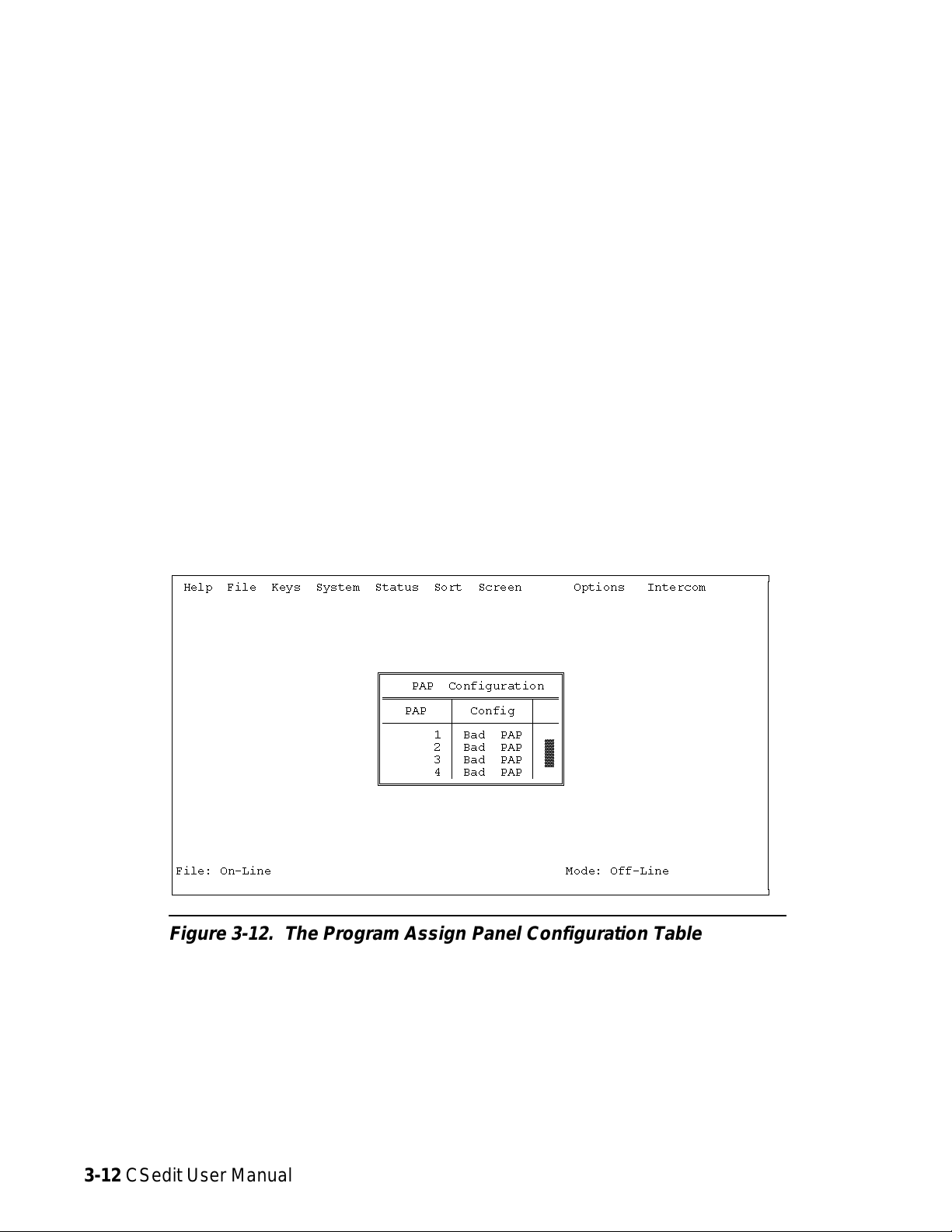
Status, PAP
When you select "PAP" from the Status menu, the
Program Assign Panel configuration table appears
(Figure 3-12).
The information displayed in the “Config” column indicates status as follows:
Bad PAP:Indicates that there has never been any data
communication with a Program Assign
Panel during the current edit session. This
could be because the device is not connected or has not been turned on.
Ok PAP Indicates that the Program Assign Panel is
connected and operating.
ÚÄÄÄÄÄÄÄÄÄÄÄÄÄÄÄÄÄÄÄÄÄÄÄÄÄÄÄÄÄÄÄÄÄÄÄÄÄÄÄÄÄÄÄÄÄÄÄÄÄÄÄÄÄÄÄÄÄÄÄÄÄÄÄÄÄÄÄÄÄÄÄÄÄÄÄÄÄÄÄÄ¿
³ Help File Keys System Status Sort Screen Options Intercom ³
³ ³
³ ³
³ ³
³ ³
³ ³
³ ³
³ ÉÍÍÍÍÍÍÍÍÍÍÍÍÍÍÍÍÍÍÍÍÍÍÍÍ» ³
³ º PAP Configuration º ³
³ ºÍÍÍÍÍÍÍÍÍÑÍÍÍÍÍÍÍÍÍÍÑÍÍͺ ³
³ º PAP ³ Config ³ º ³
³ ºÄÄÄÄÄÄÄÄÄÅÄÄÄÄÄÄÄÄÄÄÅÄÄĺ ³
³ º 1 ³ Bad PAP ³ º ³
³ º 2 ³ Bad PAP ³ ² º ³
³ º 3 ³ Bad PAP ³ ² º ³
³ º 4 ³ Bad PAP ³ º ³
³ ÈÍÍÍÍÍÍÍÍÍÍÍÍÍÍÍÍÍÍÍÍÍÍÍͼ ³
³ ³
³ ³
³ ³
³ ³
³ ³
³ ³
³File: On-Line Mode: Off-Line ³
³ ³
ÀÄÄÄÄÄÄÄÄÄÄÄÄÄÄÄÄÄÄÄÄÄÄÄÄÄÄÄÄÄÄÄÄÄÄÄÄÄÄÄÄÄÄÄÄÄÄÄÄÄÄÄÄÄÄÄÄÄÄÄÄÄÄÄÄÄÄÄÄÄÄÄÄÄÄÄÄÄÄÄÄÙ
Figure 3-12. The Program Assign Panel Configuration Table
3-12 CSedit User Manual
Page 46

Status, UIO-256
When you select "UIO-256" from the Status menu, the
UIO-256 configuration table appears (Figure 3-13).
The information displayed in the “Config” column indicates status as follows:
Bad Off: Indicates that there has never been any data
communication with a UIO-256 during the
current edit session. This could be because
the device is not connected or has not been
turned on.
ÚÄÄÄÄÄÄÄÄÄÄÄÄÄÄÄÄÄÄÄÄÄÄÄÄÄÄÄÄÄÄÄÄÄÄÄÄÄÄÄÄÄÄÄÄÄÄÄÄÄÄÄÄÄÄÄÄÄÄÄÄÄÄÄÄÄÄÄÄÄÄÄÄÄÄÄÄÄÄÄÄ¿
³ Help File Keys System Status Sort Screen Options Intercom ³
³ ³
³ ÉÍÍÍÍÍÍÍÍÍÍÍÍÍÍÍÍÍÍÍÍÍÍÍÍ» ³
³ º UIO-256 Configuration º ³
³ ºÍÍÍÍÍÍÍÍÍÑÍÍÍÍÍÍÍÍÍÍÑÍÍͺ ³
³ º UIO-256 ³ Config ³ º ³
³ ºÄÄÄÄÄÄÄÄÄÅÄÄÄÄÄÄÄÄÄÄÅÄÄĺ ³
³ º 1 ³ Bad Off ³ º ³
³ º 2³Bad Off³²º ³
³ º 3³Bad Off³²º ³
³ º 4³Bad Off³²º ³
³ º 5³Bad Off³²º ³
³ º 6³Bad Off³²º ³
³ º 7³Bad Off³²º ³
³ º 8³Bad Off³²º ³
³ º 9³Bad Off³²º ³
³ º 10³Bad Off³²º ³
³ º 11³Bad Off³²º ³
³ º 12³Bad Off³²º ³
³ º 13³Bad Off³²º ³
³ º 14³Bad Off³²º ³
³ º 15 ³ Bad Off ³ º ³
³ ÈÍÍÍÍÍÍÍÍÍÍÍÍÍÍÍÍÍÍÍÍÍÍÍͼ ³
³File: On-Line Mode: Off-Line ³
³ ³
ÀÄÄÄÄÄÄÄÄÄÄÄÄÄÄÄÄÄÄÄÄÄÄÄÄÄÄÄÄÄÄÄÄÄÄÄÄÄÄÄÄÄÄÄÄÄÄÄÄÄÄÄÄÄÄÄÄÄÄÄÄÄÄÄÄÄÄÄÄÄÄÄÄÄÄÄÄÄÄÄÄÙ
Ok Cur Indicates that the UIO-256 is connected and
operating, and that it has been updated with
the current intercom system configuration.
Ok Old Indicates that theUIO-256 is connected and
operating, but that it has not been updated
with the current intercom system configuration.
Note If several UIO-256's are connected in a "ring"
configuration, the status screen will only verify
the operation of the UIO-256 directly connected
to the intercom system.
Figure 3-13. The UIO-256 Configuration Table
CSedit User Manual 3-13
Page 47
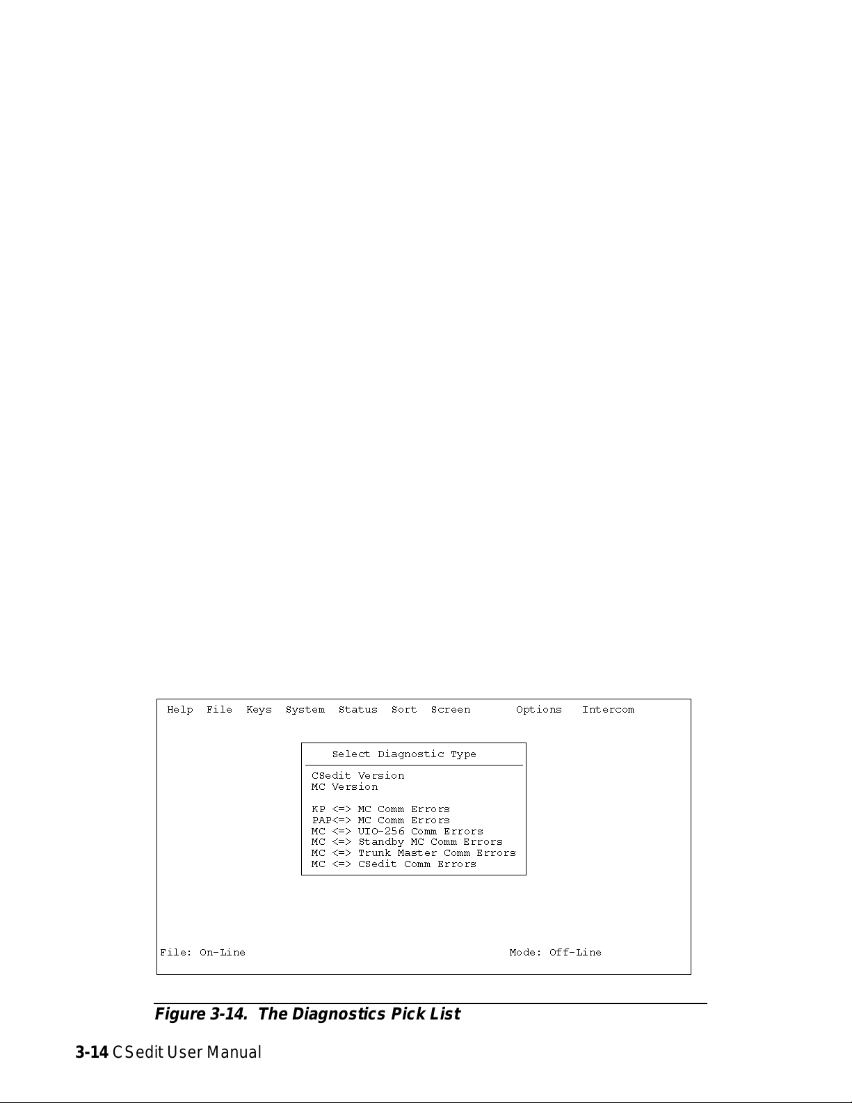
Status, Diagnostics
Whenyouselect Diagnostics fromtheStatus menu,a pick
list of available diagnostics appears (Figure 3-14).
Diagnostics, CSedit Version
This selection indicates the version number of CSedit.
Diagnostics, MC Version
Systems installed in facilities with good grounding, using
high quality telephone type twisted pair wiring will normally
operate with error rates between 0 and 20 per 24 hours. With
shielded wire, the rates are generally higher, because of the
additional cable capacitance (5-30 per 24 hours). Symptoms
of higher error rates begin to appear when the rate exceeds 1
per minute. Symptoms include cross points which remain
closed for no apparent reason, IFB’s with muted program
when no keys are closed, slow response, and general inconsistent or “flaky” operation. General causes of high error
rates include:
This selection indicates the version number of the ROM
contained in the master controller.
Diagnostics, Comm Error Screens
When you select any of the comm error items, a screen
similar to Figure 3-15 will appear. This particular screen
shows data communication errors between ports and the
master controller (MC). Port numbers are listed on the left
side of the table, followed by their names in the next column. The “Msgs From KP” column indicates transmission
errors from keypanels to the master controller. The “Msgs to
KP” column indicates transmission errors from the master
controller to keypanels. Errors are documented in two ways:
the “Err” columns indicate total accumulated errors. The
“BER” column indicates the bit error rate during the last ten
minutes of operation. The counters are reset to zero on reset
or power-up of the controller. The counters may be updated
by pressing the ENTER key. In general, error rates of no
more than one error per hour are normal. Error rates between one per hour and one per minute are higher than normal but may not cause significant problems. Error rates
greater than 1 per minute usually require immediate attention.
• Cables too long
• Poor facility grounding practices
• Crosstalk, especially when using non-twisted wir-
ing, with long parallel runs of data cables in close
proximity to each other containing differing data
streams.
• Noise induction: Keypanel cabling running paral-
lel to lighting cables etc.
• A bad keypanel: One keypanel of a group of 10
has a failed RS485 driver or processor.
• One side of a data line shorted to ground or audio
ÚÄÄÄÄÄÄÄÄÄÄÄÄÄÄÄÄÄÄÄÄÄÄÄÄÄÄÄÄÄÄÄÄÄÄÄÄÄÄÄÄÄÄÄÄÄÄÄÄÄÄÄÄÄÄÄÄÄÄÄÄÄÄÄÄÄÄÄÄÄÄÄÄÄÄÄÄÄÄÄÄ¿
³ Help File Keys System Status Sort Screen Options Intercom ³
³ ³
³ ³
³ ÚÄÄÄÄÄÄÄÄÄÄÄÄÄÄÄÄÄÄÄÄÄÄÄÄÄÄÄÄÄÄÄÄÄ¿ ³
³ ³ Select Diagnostic Type ³ ³
³ ³ÄÄÄÄÄÄÄÄÄÄÄÄÄÄÄÄÄÄÄÄÄÄÄÄÄÄÄÄÄÄÄÄij ³
³ ³ CSedit Version ³ ³
³ ³ MC Version ³ ³
³³ ³ ³
³ ³ KP <=> MC Comm Errors ³ ³
³ ³ PAP<=> MC Comm Errors ³ ³
³ ³ MC <=> UIO-256 Comm Errors ³ ³
³ ³ MC <=> Standby MC Comm Errors ³ ³
³ ³ MC <=> Trunk Master Comm Errors ³ ³
³ ³ MC <=> CSedit Comm Errors ³ ³
³ ÀÄÄÄÄÄÄÄÄÄÄÄÄÄÄÄÄÄÄÄÄÄÄÄÄÄÄÄÄÄÄÄÄÄÙ ³
³ ³
³ ³
³ ³
³ ³
³ ³
³ ³
³File: On-Line Mode: Off-Line ³
³ ³
ÀÄÄÄÄÄÄÄÄÄÄÄÄÄÄÄÄÄÄÄÄÄÄÄÄÄÄÄÄÄÄÄÄÄÄÄÄÄÄÄÄÄÄÄÄÄÄÄÄÄÄÄÄÄÄÄÄÄÄÄÄÄÄÄÄÄÄÄÄÄÄÄÄÄÄÄÄÄÄÄÄÙ
Figure 3-14. The Diagnostics Pick List
3-14 CSedit User Manual
Page 48

ÚÄÄÄÄÄÄÄÄÄÄÄÄÄÄÄÄÄÄÄÄÄÄÄÄÄÄÄÄÄÄÄÄÄÄÄÄÄÄÄÄÄÄÄÄÄÄÄÄÄÄÄÄÄÄÄÄÄÄÄÄÄÄÄÄÄÄÄÄÄÄÄÄÄÄÄÄÄÄÄÄ¿
³ Help File Keys System Status Sort Screen Options Intercom ³
³ ³
³ ÉÍÍÍÍÍÍÍÍÍÍÍÍÍÍÍÍÍÍÍÍÍÍÍÍÍÍÍÍÍÍÍÍÍÍÍÍÍÍÍÍÍÍÍÍÍÍÍÍÍÍÍÍÍ» ³
³ º KP <=> MC Comm Errors º ³
³ ºÍÍÍÍÍÑÍÍÍÍÍÍÍÍÍÍÍÍÍÑÍÍÍÍÍÍÍÍÍÍÍÍÍÍÑÍÍÍÍÍÍÍÍÍÍÍÍÍÍÑÍÍͺ ³
³ º ³ ³ Msgs From KP ³ Msgs To KP ³ º ³
³ º KP ³ Description ³ Err BER ³ Err BER ³ º ³
³ ºÄÄÄÄÄÅÄÄÄÄÄÄÄÄÄÄÄÄÄÅÄÄÄÄÄÄÄÄÄÄÄÄÄÄÅÄÄÄÄÄÄÄÄÄÄÄÄÄÄÅÄÄĺ ³
³ º 1 ³ ZXCV ³ 0 0 ³ 0 0 ³ º ³
³ º 2³BGTF ³ 0 0³ 0 0³²º ³
³ º 3³CUBI ³ 0 0³ 0 0³°º ³
³ º 4³BGTF ³ 0 0³ 0 0³°º ³
³ º 5³NJUK ³ 0 0³ 0 0³°º ³
³ º 6³OKMJ ³ 0 0³ 0 0³°º ³
³ º 7³WSDE ³ 0 0³ 0 0³°º ³
³ º 8³TFRT ³ 0 0³ 0 0³°º ³
³ º 9³BHGT ³ 0 0³ 0 0³°º ³
³ º 10³UHJN ³ 0 0³ 0 0³°º ³
³ º 11³OKLP ³ 0 0³ 0 0³°º ³
³ º 12³CDES ³ 0 0³ 0 0³°º ³
³ º 13³AWAW ³ 0 0³ 0 0³°º ³
³ º 14³VCFG ³ 0 0³ 0 0³▼º³
³ ÈÍÍÍÍÍÍÍÍÍÍÍÍÍÍÍÍÍÍÍÍÍÍÍÍÍÍÍÍÍÍÍÍÍÍÍÍÍÍÍÍÍÍÍÍÍÍÍÍÍÍÍÍͼ ³
³File: On-Line Mode: Off-Line ³
³ ³
ÀÄÄÄÄÄÄÄÄÄÄÄÄÄÄÄÄÄÄÄÄÄÄÄÄÄÄÄÄÄÄÄÄÄÄÄÄÄÄÄÄÄÄÄÄÄÄÄÄÄÄÄÄÄÄÄÄÄÄÄÄÄÄÄÄÄÄÄÄÄÄÄÄÄÄÄÄÄÄÄÄÙ
Figure 3-15. A Typical Communications Error Screen
System, Digital Inputs
The digital inputs screen lets you assign the inputs of an
optional UIO-256 frame to simulate keypanel keys. The
digital inputs screen can also be used to assign the eight
digital inputs available at the J903 connector on the back
of an ADAM CS frame.
ÚÄÄÄÄÄÄÄÄÄÄÄÄÄÄÄÄÄÄÄÄÄÄÄÄÄÄÄÄÄÄÄÄÄÄÄÄÄÄÄÄÄÄÄÄÄÄÄÄÄÄÄÄÄÄÄÄÄÄÄÄÄÄÄÄÄÄÄÄÄÄÄÄÄÄÄÄÄÄÄÄ¿
³ Help File Keys System Status Sort Screen Options Intercom ³
³ ÉÍÍÍÍÍÍÍÍÍÍÍÍÍÍÍÍÍÍÍÍÍÍÍÍÍÍÍÍÍÍÍÍÍÍ» ÉÍÍÍÍÍÍÍÍÍÍÍÍÍÍÍÍ» ³
³ º Digital Input Assignments º º Outputs º ³
³ ºÍÍÍÍÑÍÍÍÑÍÍÍÍÍÍÍÍÍÑÍÍÍÍÍÑÍÍÍÍÍÑÍÍͺ ºÍÍÍÍÍÍÑÍÍÍÍÍÑÍÍͺ ³
³ ºInp ³Chg³Key Panel³ Key ³ T/L ³ º ºAlpha ³Port ³ º ³
³ ºÄÄÄÄÅÄÄÄÅÄÄÄÄÄÄÄÄÄÅÄÄÄÄÄÅÄÄÄÄÄÅÄÄĺ ºÄÄÄÄÄÄÅÄÄÄÄÄÅÄÄĺ ³
³ º1 ³û³N001 1³1 ³úT ³ º ºN001³1 ³°º ³
³ º2 ³ú³----ú ³ú ³ú ³²º ºN002³2 ³°º ³
³ º3 ³ú³----ú ³ú ³ú ³²º ºN003³3 ³°º ³
³ º4 ³ú³----ú ³ú ³ú ³²º ºN004³4 ³°º ³
³ º5 ³ú³----ú ³ú ³ú ³²º ºN005³5 ³°º ³
³ º6 ³ú³----ú ³ú ³ú ³°º ºN006³6 ³°º ³
³ º7 ³ú³----ú ³ú ³ú ³°º ºN007³7 ³²º ³
³ º8 ³ú³----ú ³ú ³ú ³°º ºN008³8 ³°º ³
³ º9 ³ú³----ú ³ú ³ú ³°º ºN009³9 ³°º ³
³ º10³ú³----ú ³ú ³ú ³°º ºN010³10 ³°º ³
³ º11³ú³----ú ³ú ³ú ³°º ºN011³11 ³°º ³
³ º12³ú³----ú ³ú ³ú ³°º ºN012³12 ³°º ³
³ º13³ú³----ú ³ú ³ú ³°º ºN013³13 ³°º ³
³ º14³ú³----ú ³ú ³ú ³°º ºN014³14 ³°º ³
³ º15³ú³----ú ³ú ³ú ³°º ºN015³15 ³°º ³
³ º16³ú³----ú ³ú ³ú ³▼º º N016 ³ 16 ³▼º³
³ ÈÍÍÍÍÍÍÍÍÍÍÍÍÍÍÍÍÍÍÍÍÍÍÍÍÍÍÍÍÍÍÍÍÍͼ ÈÍÍÍÍÍÍÍÍÍÍÍÍÍÍÍͼ ³
³File: New Mode: Off-Line ³
³ ³
ÀÄÄÄÄÄÄÄÄÄÄÄÄÄÄÄÄÄÄÄÄÄÄÄÄÄÄÄÄÄÄÄÄÄÄÄÄÄÄÄÄÄÄÄÄÄÄÄÄÄÄÄÄÄÄÄÄÄÄÄÄÄÄÄÄÄÄÄÄÄÄÄÄÄÄÄÄÄÄÄÄÙ
Figure 3-16. The Digital Input Edit Screen
When you select Digital Inputs from the System menu,
the Digital Input Edit Screen should appear (Figure 3-16).
In the example, digital input #1 has been assigned to simulate talk key #1 for intercom port N001.
CSedit User Manual 3-15
Page 49

System, Force & Inhibit
to the port at the left”. The “→M→” columns provide the
following indications:
General Usage
You can force a crosspoint to create a continuously activated talk and/or listen path between a selected port and
any other port. You can also inhibit crosspoints to block
communications between selected ports. Finally, you can
view all the connections from a selected port to all other
ports.
Force is commonly used to establishcommunication paths
through the matrix when the inputs and outputs involved
are not keypanels. It can also be used with keypanels to
force communication paths to be on continuously. Inhibit
is used to restrict communication between keypanels. It is
commonly used to prevent feedback between adjacent keypanels when they are using the same party line. Inhibiting
the two crosspoints between adjacent keypanels will effectively “mix minus” the two keypanels without affecting
communication with other ports on the party line.
When you select "Force & Inhibit" from the System
menu, a pick list of ports will appear (Figure 3-17). Select a port from the pick list to view the force & inhibit
screen for that port.
Figure 3-18 shows the force inhibit screen for port N001.
The name of the selected port is shown in the window at
the upper right. The names of all connecting ports and
their port numbers are displayed in the “Alph” and “Port”
columns of the “Connecting Ports” table. The “→M→”
column is actually two columns. The “→M” column indicates “from the port at the left to me”, where “me” in this
case is port N001. The “M→” column indicates “from me
ÚÄÄÄÄÄÄÄÄÄÄÄÄÄÄÄÄÄÄÄÄÄÄÄÄÄÄÄÄÄÄÄÄÄÄÄÄÄÄÄÄÄÄÄÄÄÄÄÄÄÄÄÄÄÄÄÄÄÄÄÄÄÄÄÄÄÄÄÄÄÄÄÄÄÄÄÄÄÄÄÄ¿
³ Help File Keys System Status Sort Screen Options Intercom ³
³ ÉÍÍÍÍÍÍÍÍÍÍÍÍÍÍÍÍ» ÉÍÍÍÍÍÍÍÍÍÍÍÍÍÍÍÍÍÍÍÍÍÍÍÍÍÍÍÍ»³
³ ºAlpha ³Port ³ º º Alpha N001 Port 1 º³
³ ºÄÄÄÄÄÄÅÄÄÄÄÄÅÄÄĺ ÈÍÍÍÍÍÍÍÍÍÍÍÍÍÍÍÍÍÍÍÍÍÍÍÍÍÍÍͼ³
³ º N001 ³ 1 ³ º ³
³ º N002 ³ 2 ³ ² º ³
³ º N003 ³ 3 ³ ° º ³
³ º N004 ³ 4 ³ ° º ³
³ º N005 ³ 5 ³ ° º ³
³ º N006 ³ 6 ³ ° º ³
³ º N007 ³ 7 ³ ° º ³
³ º N008 ³ 8 ³ ° º ³
³ º N009 ³ 9 ³ ° º ³
³ º N010 ³ 10 ³ ° º ³
³ º N011 ³ 11 ³ ° º ³
³ º N012 ³ 12 ³ ° º ³
³ º N013 ³ 13 ³ ° º ³
³ º N014 ³ 14 ³ ° º ³
³ º N015 ³ 15 ³ ° º ³
³ º N016 ³ 16 ³ ° º ³
³ º N017 ³ 17 ³ ° º ³
³ º N018 ³ 18 ³▼º³
³ ÈÍÍÍÍÍÍÍÍÍÍÍÍÍÍÍͼ ³
³File: New Mode: Off-Line ³
³ ³
ÀÄÄÄÄÄÄÄÄÄÄÄÄÄÄÄÄÄÄÄÄÄÄÄÄÄÄÄÄÄÄÄÄÄÄÄÄÄÄÄÄÄÄÄÄÄÄÄÄÄÄÄÄÄÄÄÄÄÄÄÄÄÄÄÄÄÄÄÄÄÄÄÄÄÄÄÄÄÄÄÄÙ
F: Indicates that a crosspoint is “forced” closed
I: Indicates that a crosspoint is “inhibited”, or prevented
from closing
û
: Indicates that a crosspoint is currently closed (a key-
panel key is activated)
A blank space indicates that a crosspoint is neither forced
nor inhibited nor currently closed.
To change the setting of a crosspoint: Use the cursor
keys to select the desired crosspoint, then use the space
bar to change the setting. (Or, simply click on a crosspoint with a mouse.) Once you have made any desired
changes, press the ESCAPE key to return to the menu
bar. Then, select "Activate Chgs" from the Intercom
menu to send the changes to the intercom system.
Note: If keypanel keys are turned on and off while the
force & inhibit screen is displayed, the screen
may not show it. To update the screen and see
which crosspoints are currently closed, press the
ENTER key. Each time you press the ENTER
key, CSedit will upload the current crosspoint
status from the intercom system. If you modify
any crosspoint settings, you should first send
your changes to the intercom before performing
a screen update. Otherwise, your changes may
be erased.
Figure 3-17. The Pick List for Force and Inhibit
3-16 CSedit User Manual
Page 50

ÚÄÄÄÄÄÄÄÄÄÄÄÄÄÄÄÄÄÄÄÄÄÄÄÄÄÄÄÄÄÄÄÄÄÄÄÄÄÄÄÄÄÄÄÄÄÄÄÄÄÄÄÄÄÄÄÄÄÄÄÄÄÄÄÄÄÄÄÄÄÄÄÄÄÄÄÄÄÄÄÄ¿
³ Help File Keys System Status Sort Screen Options Intercom ³
³ ÉÍÍÍÍÍÍÍÍÍÍÍÍÍÍÍÍÍÍÍÍÍÍÍÍÍÍ»³
³ º Alpha N001 Port 1 º³
³ º Data Changed û º³
³ ÈÍÍÍÍÍÍÍÍÍÍÍÍÍÍÍÍÍÍÍÍÍÍÍÍÍͼ³
³ ³
³ÉÍÍÍÍÍÍÍÍÍÍÍÍÍÍÍÍÍÍÍÍÍÍÍÍÍÍÍÍÍÍÍÍÍÍÍÍÍÍÍÍÍÍÍÍÍÍÍÍÍÍÍÍÍÍÍÍÍÍÍÍÍÍÍÍÍÍÍÍÍÍÍÍÍÍÍÍÍÍ»³
³º Connecting Ports º³
³ºÄÄÄÄÂÄÄÄÄÄÂÄÄÄÒÄÄÄÄÂÄÄÄÄÄÂÄÄÄÒÄÄÄÄÂÄÄÄÄÄÂÄÄÄÒÄÄÄÄÂÄÄÄÄÄÂÄÄÄÒÄÄÄÄÂÄÄÄÄÄÂÄÄÄÂÄÄĺ³
³ºAlph³Port ³→M→ºAlph³Port ³→M→ºAlph³Port ³→M→ºAlph³Port ³→M→ºAlph³Port ³→M→³º³
³ºÄÄÄÄÅÄÄÄÄÄÅÄÄÄ×ÄÄÄÄÅÄÄÄÄÄÅÄÄÄ×ÄÄÄÄÅÄÄÄÄÄÅÄÄÄ×ÄÄÄÄÅÄÄÄÄÄÅÄÄÄ×ÄÄÄÄÅÄÄÄÄÄÅÄÄÄÅÄÄĺ³
³ºN001³1³ºN002³2³ºN003³3³ºN004³4³ºN005³5³³º³
³ºN006³ 6 ³û ºN007³ 7 ³ ºN008³ 8 ³û ºN009³ 9 ³ ºN010³ 10 ³ ³ ² º³
³ºN011³ 11 ³ ºN012³ 12 ³ ºN013³ 13 ³ ºN014³ 14 ³ ºN015³ 15 ³ ³ ° º³
³ºN016³ 16 ³ ºN017³ 17 ³ ºN018³ 18 ³ ºN019³ 19 ³ ºN020³ 20 ³ ³ ° º³
³ºN021³ 21 ³û ûºN022³ 22 ³ IºN023³ 23 ³ ºN024³ 24 ³F ºN025³ 25 ³ ³ ° º³
³ºN026³ 26 ³ ºN027³ 27 ³ ºN028³ 28 ³F ºN029³ 29 ³ ºN030³ 30 ³ ³ ° º³
³ºN031³ 31 ³F ºN032³ 32 ³ ºN033³ 33 ³ ºN034³ 34 ³ ºN035³ 35 ³ ³ ° º³
³ºN036³ 36 ³ ºN037³ 37 ³ ºN038³ 38 ³ ûºN039³ 39 ³ ºN040³ 40 ³ ³ ° º³
³ºN041³ 41 ³ FºN042³ 42 ³ ºN043³ 43 ³ ºN044³ 44 ³ ºN045³ 45 ³û ³ ° º³
³ºN046³ 46 ³ ºN047³ 47 ³ ºN048³ 48 ³ FºN049³ 49 ³ FºN050³ 50 ³ ³▼º³
³ÈÍÍÍÍÍÍÍÍÍÍÍÍÍÍÍÍÍÍÍÍÍÍÍÍÍÍÍÍÍÍÍÍÍÍÍÍÍÍÍÍÍÍÍÍÍÍÍÍÍÍÍÍÍÍÍÍÍÍÍÍÍÍÍÍÍÍÍÍÍÍÍÍÍÍÍÍÍͼ³
³ ³
³File: On-Line Mode: Off-Line ³
³ ³
ÀÄÄÄÄÄÄÄÄÄÄÄÄÄÄÄÄÄÄÄÄÄÄÄÄÄÄÄÄÄÄÄÄÄÄÄÄÄÄÄÄÄÄÄÄÄÄÄÄÄÄÄÄÄÄÄÄÄÄÄÄÄÄÄÄÄÄÄÄÄÄÄÄÄÄÄÄÄÄÄÄÙ
Figure 3-18. Typical Force & Inhibit Screen (Port Alpha N001 Shown)
Typical Application of Forced Crosspoint
Example: Suppose you want to create an output with the
director and producer permanently on it, and distribute this
output to the studio floor. To do this, proceed as follows:
1. Connect a matrix output to the studio distribution amplifier.
2. From the System menu select "Key Panel Alphas", and
name the output to the amplifier “HOT” (for “hot mic”).
3. From the System menu, select "Force & Inhibit".
4. Select the director’s panel from the force and inhibit
pick list. Then, insert an "F" in the “M→” column
ÚÄÄÄÄÄÄÄÄÄÄÄÄÄÄÄÄÄÄÄÄÄÄÄÄÄÄÄÄÄÄÄÄÄÄÄÄÄÄÄÄÄÄÄÄÄÄÄÄÄÄÄÄÄÄÄÄÄÄÄÄÄÄÄÄÄÄÄÄÄÄÄÄÄÄÄÄÄÄÄÄ¿
³ Help File Keys System Status Sort Screen Options Intercom ³
³ ÉÍÍÍÍÍÍÍÍÍÍÍÍÍÍÍÍÍÍÍÍÍÍÍÍÍÍ»³
³ º Alpha DIR Port 1 º³
³ º Data Changed û º³
³ ÈÍÍÍÍÍÍÍÍÍÍÍÍÍÍÍÍÍÍÍÍÍÍÍÍÍͼ³
³ ³
³ÉÍÍÍÍÍÍÍÍÍÍÍÍÍÍÍÍÍÍÍÍÍÍÍÍÍÍÍÍÍÍÍÍÍÍÍÍÍÍÍÍÍÍÍÍÍÍÍÍÍÍÍÍÍÍÍÍÍÍÍÍÍÍÍÍÍÍÍÍÍÍÍÍÍÍÍÍÍÍ»³
³º Connecting Ports º³
³ºÄÄÄÄÂÄÄÄÄÄÂÄÄÄÒÄÄÄÄÂÄÄÄÄÄÂÄÄÄÒÄÄÄÄÂÄÄÄÄÄÂÄÄÄÒÄÄÄÄÂÄÄÄÄÄÂÄÄÄÒÄÄÄÄÂÄÄÄÄÄÂÄÄÄÂÄÄĺ³
³ºAlph³Port ³→M→ºAlph³Port ³→M→ºAlph³Port ³→M→ºAlph³Port ³→M→ºAlph³Port ³→M→³º³
³ºÄÄÄÄÅÄÄÄÄÄÅÄÄÄ×ÄÄÄÄÅÄÄÄÄÄÅÄÄÄ×ÄÄÄÄÅÄÄÄÄÄÅÄÄÄ×ÄÄÄÄÅÄÄÄÄÄÅÄÄÄ×ÄÄÄÄÅÄÄÄÄÄÅÄÄÄÅÄÄĺ³
³ºDIR ³ 1 ³ ºPROD³ 2 ³ ºHOT ³ 3 ³ FºN004³ 4 ³ ºN005³ 5 ³ ³ º³
³ºN006³ 6 ³ ºN007³ 7 ³ ºN008³ 8 ³ ºN009³ 9 ³ ºN010³ 10 ³ ³ ² º³
³ºN011³ 11 ³ ºN012³ 12 ³ ºN013³ 13 ³ ºN014³ 14 ³ ºN015³ 15 ³ ³ ° º³
³ºN016³ 16 ³ ºN017³ 17 ³ ºN018³ 18 ³ ºN019³ 19 ³ ºN020³ 20 ³ ³ ° º³
³ºN021³ 21 ³ ºN022³ 22 ³ ºN023³ 23 ³ ºN024³ 24 ³ ºN025³ 25 ³ ³ ° º³
³ºN026³ 26 ³ ºN027³ 27 ³ ºN028³ 28 ³ ºN029³ 29 ³ ºN030³ 30 ³ ³ ° º³
³ºN031³ 31 ³ ºN032³ 32 ³ ºN033³ 33 ³ ºN034³ 34 ³ ºN035³ 35 ³ ³ ° º³
³ºN036³ 36 ³ ºN037³ 37 ³ ºN038³ 38 ³ ºN039³ 39 ³ ºN040³ 40 ³ ³ ° º³
³ºN041³ 41 ³ ºN042³ 42 ³ ºN043³ 43 ³ ºN044³ 44 ³ ºN045³ 45 ³ ³ ° º³
³ºN046³ 46 ³ ºN047³ 47 ³ ºN048³ 48 ³ ºN049³ 49 ³ ºN050³ 50 ³ ³▼º³
³ÈÍÍÍÍÍÍÍÍÍÍÍÍÍÍÍÍÍÍÍÍÍÍÍÍÍÍÍÍÍÍÍÍÍÍÍÍÍÍÍÍÍÍÍÍÍÍÍÍÍÍÍÍÍÍÍÍÍÍÍÍÍÍÍÍÍÍÍÍÍÍÍÍÍÍÍÍÍͼ³
³ ³
³File: On-Line Mode: Off-Line ³
³ ³
ÀÄÄÄÄÄÄÄÄÄÄÄÄÄÄÄÄÄÄÄÄÄÄÄÄÄÄÄÄÄÄÄÄÄÄÄÄÄÄÄÄÄÄÄÄÄÄÄÄÄÄÄÄÄÄÄÄÄÄÄÄÄÄÄÄÄÄÄÄÄÄÄÄÄÄÄÄÄÄÄÄÙ
next to the port named "HOT", as shown in Figure 3-
19.
5. Press the ESCAPE key to return to the force and inhibit
pick list. Then, select the producer’s panel. Insert an
"F" in the “M→” column next to the port named
"HOT", as shown in Figure 3-20.
6. Press the ESCAPE key as required to return to the
menu bar.
7. Send the changes to the intercom system. The director
and producer will now both have hot mics to the output HOT, which you have distributed to the studio
floor.
Figure 3-19. Director Microphone Forced to Output “HOT”
CSedit User Manual 3-17
Page 51

ÚÄÄÄÄÄÄÄÄÄÄÄÄÄÄÄÄÄÄÄÄÄÄÄÄÄÄÄÄÄÄÄÄÄÄÄÄÄÄÄÄÄÄÄÄÄÄÄÄÄÄÄÄÄÄÄÄÄÄÄÄÄÄÄÄÄÄÄÄÄÄÄÄÄÄÄÄÄÄÄÄ¿
³ Help File Keys System Status Sort Screen Options Intercom ³
³ ÉÍÍÍÍÍÍÍÍÍÍÍÍÍÍÍÍÍÍÍÍÍÍÍÍÍÍ»³
³ º Alpha PROD Port 2 º³
³ º Data Changed û º³
³ ÈÍÍÍÍÍÍÍÍÍÍÍÍÍÍÍÍÍÍÍÍÍÍÍÍÍͼ³
³ ³
³ÉÍÍÍÍÍÍÍÍÍÍÍÍÍÍÍÍÍÍÍÍÍÍÍÍÍÍÍÍÍÍÍÍÍÍÍÍÍÍÍÍÍÍÍÍÍÍÍÍÍÍÍÍÍÍÍÍÍÍÍÍÍÍÍÍÍÍÍÍÍÍÍÍÍÍÍÍÍÍ»³
³º Connecting Ports º³
³ºÄÄÄÄÂÄÄÄÄÄÂÄÄÄÒÄÄÄÄÂÄÄÄÄÄÂÄÄÄÒÄÄÄÄÂÄÄÄÄÄÂÄÄÄÒÄÄÄÄÂÄÄÄÄÄÂÄÄÄÒÄÄÄÄÂÄÄÄÄÄÂÄÄÄÂÄÄĺ³
³ºAlph³Port ³→M→ºAlph³Port ³→M→ºAlph³Port ³→M→ºAlph³Port ³→M→ºAlph³Port ³→M→³º³
³ºÄÄÄÄÅÄÄÄÄÄÅÄÄÄ×ÄÄÄÄÅÄÄÄÄÄÅÄÄÄ×ÄÄÄÄÅÄÄÄÄÄÅÄÄÄ×ÄÄÄÄÅÄÄÄÄÄÅÄÄÄ×ÄÄÄÄÅÄÄÄÄÄÅÄÄÄÅÄÄĺ³
³ºDIR ³ 1 ³ ºPROD³ 2 ³ ºHOT ³ 3 ³ FºN004³ 4 ³ ºN005³ 5 ³ ³ º³
³ºN006³ 6 ³ ºN007³ 7 ³ ºN008³ 8 ³ ºN009³ 9 ³ ºN010³ 10 ³ ³ ² º³
³ºN011³ 11 ³ ºN012³ 12 ³ ºN013³ 13 ³ ºN014³ 14 ³ ºN015³ 15 ³ ³ ° º³
³ºN016³ 16 ³ ºN017³ 17 ³ ºN018³ 18 ³ ºN019³ 19 ³ ºN020³ 20 ³ ³ ° º³
³ºN021³ 21 ³ ºN022³ 22 ³ ºN023³ 23 ³ ºN024³ 24 ³ ºN025³ 25 ³ ³ ° º³
³ºN026³ 26 ³ ºN027³ 27 ³ ºN028³ 28 ³ ºN029³ 29 ³ ºN030³ 30 ³ ³ ° º³
³ºN031³ 31 ³ ºN032³ 32 ³ ºN033³ 33 ³ ºN034³ 34 ³ ºN035³ 35 ³ ³ ° º³
³ºN036³ 36 ³ ºN037³ 37 ³ ºN038³ 38 ³ ºN039³ 39 ³ ºN040³ 40 ³ ³ ° º³
³ºN041³ 41 ³ ºN042³ 42 ³ ºN043³ 43 ³ ºN044³ 44 ³ ºN045³ 45 ³ ³ ° º³
³ºN046³ 46 ³ ºN047³ 47 ³ ºN048³ 48 ³ ºN049³ 49 ³ ºN050³ 50 ³ ³▼º³
³ÈÍÍÍÍÍÍÍÍÍÍÍÍÍÍÍÍÍÍÍÍÍÍÍÍÍÍÍÍÍÍÍÍÍÍÍÍÍÍÍÍÍÍÍÍÍÍÍÍÍÍÍÍÍÍÍÍÍÍÍÍÍÍÍÍÍÍÍÍÍÍÍÍÍÍÍÍÍͼ³
³ ³
³File: On-Line Mode: Off-Line ³
³ ³
ÀÄÄÄÄÄÄÄÄÄÄÄÄÄÄÄÄÄÄÄÄÄÄÄÄÄÄÄÄÄÄÄÄÄÄÄÄÄÄÄÄÄÄÄÄÄÄÄÄÄÄÄÄÄÄÄÄÄÄÄÄÄÄÄÄÄÄÄÄÄÄÄÄÄÄÄÄÄÄÄÄÙ
Figure 3-20. Producer Microphone Forced to Output “HOT”
System, Special Functions
When you select “Special Functions” from the System
menu, the Special Function Assignments screen will appear (Figure 3-21). This screen allows you to restrict access to the special function key assignments or rename
the special functions. To apply restrictions, move to the
“AUC” column. Use the SPACE BAR or click with a
mouse to place or remove check marks as desired:
A Access Restricted: A check mark under “A” prevents
keypanel operators in your intercom system from assigning this special function to keys from their keypanels.
ÚÄÄÄÄÄÄÄÄÄÄÄÄÄÄÄÄÄÄÄÄÄÄÄÄÄÄÄÄÄÄÄÄÄÄÄÄÄÄÄÄÄÄÄÄÄÄÄÄÄÄÄÄÄÄÄÄÄÄÄÄÄÄÄÄÄÄÄÄÄÄÄÄÄÄÄÄÄÄÄÄ¿
³ Help File Keys System Status Sort Screen Options Intercom ³
³ ³
³ ³
³ ³
³ ³
³ ³
³ ÉÍÍÍÍÍÍÍÍÍÍÍÍÍÍÍÍÍÍÍÍÍÍÍÍÍÍÍÍÍÍÍÍÍÍÍÍÍÍÍÍÍ» ³
³ º Special Function Assignments º ³
³ ºÍÍÍÍÍÍÑÍÍÍÍÍÍÍÍÍÍÍÍÍÍÍÍÍÍÑÍÍÍÍÍÑÍÍÍÍÍÑÍÍͺ ³
³ ºAlpha ³ Special Function ³ Chg ³ AUC ³ º ³
³ ºÄÄÄÄÄÄÅÄÄÄÄÄÄÄÄÄÄÄÄÄÄÄÄÄÄÅÄÄÄÄÄÅÄÄÄÄÄÅÄÄĺ ³
³ º ---- ³ No Assignment ³ ú ³ úûû ³ º ³
³ º AC ³ All Call ³ ú ³ úûû ³ ² º ³
³ º AF ³ Auto-Follow ³ ú ³ úûû ³ ² º ³
³ º AL ³ Auto-Listen ³ ú ³ ûûû ³ ² º ³
³ º AR ³ Auto-Reciprocal ³ û ³ úûû ³ ² º ³
³ º AM ³ Auto-Mute ³ ú ³ úûû ³ º ³
³ ÈÍÍÍÍÍÍÍÍÍÍÍÍÍÍÍÍÍÍÍÍÍÍÍÍÍÍÍÍÍÍÍÍÍÍÍÍÍÍÍÍͼ ³
³ ³
³ ³
³ ³
³ ³
³ ³
³File: New Mode: Off-Line ³
³ ³
ÀÄÄÄÄÄÄÄÄÄÄÄÄÄÄÄÄÄÄÄÄÄÄÄÄÄÄÄÄÄÄÄÄÄÄÄÄÄÄÄÄÄÄÄÄÄÄÄÄÄÄÄÄÄÄÄÄÄÄÄÄÄÄÄÄÄÄÄÄÄÄÄÄÄÄÄÄÄÄÄÄÙ
U Univ Scroll Restricted: If your intercom system is
trunked with other intercom systems, a check mark
under “U” prevents keypanel operators in the other
intercom systems from assigning this special function to keys from their keypanels. Normally you will
want to restrict outside keypanel access, so a check
mark is placed here by default.
C CSedit Scroll Restricted: A check mark under “C” pre-
vents CSedit users on other intercom systems from assigning this special function in their intercom systems.
Normally you will want to restrict outside CSedit access, so a check mark is placed here by default.
To rename a special function, position the cursor in the
“Alpha” column and enter a new name (4 characters max.)
Figure 3-21. The Special Function Assignments Screen
3-18 CSedit User Manual
Page 52

Appendix
PC to Intercom System Interconnect Cable Wiring for ADAM Intercom
ADAM
BREAKOUT PANEL, J1
RX 2
TX 3
GND 5
RTS 7
CTS 8
9-PIN MALE
CONNECTOR
ADAM
BREAKOUT PANEL, J1
RX 2
TX 3
GND 5
RTS 7
9-PIN TO 25-PIN CABLE
9-PIN TO 9-PIN CABLE
COMPUTER
2TX
3RX
7 GND
25-PIN FEMALE
CONNECTOR
COMPUTER
2RX
3TX
5 GND
CTS 8
9-PIN MALE
CONNECTOR
9-PIN FEMALE
CONNECTOR
CSedit User Manual A-1
Page 53

PC to Intercom System Interconnect Cable Wiring for ADAM CS Intercom
TO ADAMCS, J900
RX 4
TX 3
GND 1
9-PIN MALE
CONNECTOR
(DE-9P)
TO ADAMCS, J900
RX 4
TX 3
GND 1
9-PIN MALE
CONNECTOR
(DE-9P)
9-PIN TO 25-PIN CABLE
9-PIN TO 9-PIN CABLE
TO COMPUTER
2 TX
3 RX
7 GND
25-PIN FEMALE
CONNECTOR
(DB-25S)
TO COMPUTER
2 RX
3 TX
5 GND
9-PIN FEMALE
CONNECTOR
(DE-9S)
ADAM CS FRAME WITH FEMALE J900 CONNECTOR
TO ADAMCS, J900
RX 2
TX 3
GND 5
9-PIN FEMALE
CONNECTOR
(DE-9S)
TO ADAMCS, J900
RX 2
TX 3
GND 5
9-PIN FEMALE
CONNECTOR
(DE-9S)
A-2 CSedit User Manual
9-PIN TO 25-PIN CABLE
9-PIN TO 9-PIN CABLE
TO COMPUTER
25-PIN FEMALE
CONNECTOR
(DB-25S)
TO COMPUTER
9-PIN FEMALE
CONNECTOR
(DE-9S)
ADAM CS FRAME WITH MALE J900 CONNECTOR
2 TX
3 RX
7 GND
2 RX
3 TX
5 GND
Page 54

Index
A
Activating a New File or Sending Changes 1-4
Alias 2-1
All Call Special Function (AC) 2-18
Alpha 2-1
Assigning Names (Alphas & Aliases) 2-1
Auto Listen Special Function (AL) 2-19
Auto Mute Special Function (AM) 2-19
Auto Reciprocal Special Function (AR) 2-19
Auto-Follow Special Function (AF) 2-18
B
BACK SPACE Key in a Help Screen 1-4
Baud Rate 3-7
C
Camera ISO
See ISO
Cancel Screen Chg 3-8
Change Flags 1-4
Color 3-5
Color Chart 3-2
Colors 3-1
Com Port 3-6
Comm Error Screens 3-14
Computer Requirements iii
Configuration Files 1-4
Copy Screen
Copying a keypanel setup 2-19
General description 3-8
Copying and Pasting Edit Screens 3-2
Create New File 1-4
Creating a Party Line 2-3
Creating a Special List 2-8
CSedit Files 3-2
CSedit menu screen 1-1
CSedit Version 3-14
CSEDIT.SET File Line Usage 3-1
CStrunk 2-1
CURSOR Keys 1-3
D
Diagnostics 3-14
Digital Inputs 3-15
Digital outputs 2-8
E
Editing a Configuration 1-4
EKP-12, EKP-16 and EKP-20 expansion panels
Key assignments 2-18
Setup page assignments 2-22
ENTER Key 1-3
ESCAPE Key 1-3
ESCAPE Key in Help 1-4
F
Files 3-2
Force & Inhibit 3-16
Forced Crosspoint 3-17
FR9528 Frame 2-8
function keys 1-2
I
IFB (Interrupt Foldback Bus)
Creating an IFB ( Interrupt Foldback Bus) 2-6
Remote IFB 3-7
Setting IFB and Trunking Priorities 2-21
Installing CSedit 1-1
ISO
Creating a Camera ISO Channel 2-13
Naming 2-2
J
J903 2-8
K
Key Assignment (Talk/Listen Key 2-17
Key Panel Setup 2-15
Key Words in Help Screens 1-3
Keypanel Edit Screen 2-16
KP-12 keypanel
Key assignments 2-18
Setup page assignments 2-22
L
laptop computer 1-1
Changing the color mapping for grey-scale displays 3-6
Using a monchrome display 1-1
Level 1 and 2 talk key 2-17
Listen Key Assignments 2-17
M
MC Version 3-14
Menu Selection Using a Mouse 1-2
Menu Selection Using the Computer Keyboard 1-2
monochrome display 1-1
CSedit User Manual I-1
Page 55

mouse 3-6
Movement in Editing Screens Using a Mouse 1-3
Movement in Editing Screens Using the Computer Keyboard 1-3
Moving a User to a New Port 3-2
N
Naming Individual Audio Ports 2-1
Naming Party Lines, ISO’s etc. 2-2
O
Open Existing File 1-4
Options Menu 3-5
Options, Color 3-5
Options, Communications 3-6
Oscillator 2-21
P
Page 2-21
PAP 3-12
Party Line 2-3
Paste Screen
Copying a keypanel setup 2-19
General description 3-8
Plus “+” Key on Numeric Keypad 1-3
Port 3-9
Port Alpha Assignments 2-2
Port Information 2-20
Port Restrictions 2-20
Program Assign Panel 3-12
S
Saving Changes 1-4
Screen Colors 3-1
Screen Menu 3-8
Scrolling in Help Screens 1-4
Search
General description 3-2
Using to move a user to a new port 3-2
Sending Changes 1-4
Setup Page 2-21
Special Functions 3-18
Special List 2-8
Special List Relay Assignments 2-8
Speed Formatting 3-8
Stacked talk key 2-17
Standby Controller 3-10
Starting CSedit 1-1
Status Menu 3-9
T
TAB Key 1-3
Talk Key Assignments 2-17
Talk level 1 and 2 2-17
Target Assignment 3-3
Tone Oscillator 2-21
Trunk Master 3-11
Trunking
Assigning a trunking priority to a keypanel 2-21
Restricting a port for use as a trunking port 2-21
Selecting an intercom system for search 3-3
Type Styles iii
Q
Quitting CSedit 1-4
R
Relays
Assigning for activation by keypanel keys 2-11
Using with special lists 2-8
Remote IFB 3-7
Restrict
Additional requirements for a trunked intercom system 2-1
Restricting a party line 2-5
Restricting a relay 2-12
Restricting a special list 2-10
Restricting an IFB 2-7
Restricting an intercom port 2-20
Restricting an ISO 2-13
Restricting keys on a keypanel 2-17
U
UIO-256
Assigning relays for use by a special list 2-8
Reading the UIO-256 status screen 3-13
V
Version Number iii
I-2 CSedit User Manual
Page 56

ADAM
TM
ADVANCED DIGITAL AUDIO MATRIX
ADDENDUM 1
Intercom System Effectivity: ADAM AND ADAM CS
Manual Effectivity: CSedit User Manual, 9350-7077-300, Rev B, 8/96
Description: Logging Feature
™
Page 57

2 Logging Addendum, CSedit User Manual for ADAM and ADAM CS Intercom Systems
Page 58

Introduction
This addendum supplements manual number 9350-7077-300, Revision B, “CSedit Intercom Configuration Software for
ADAM and ADAM CS Intercom Systems”. It describes the logging feature which was added to CSedit.
Logging Description
You use logging to record intercom key activations and deactivations. Each time a key is pressed or released, a new
record is created. If you select Log to File, each new record will be uploaded to the configuration computer and
appended to a text file. You specify the directory where the text file is stored (the default directory is the directory
where the CSedit program is located), while the name for the text file is created by CSedit and is of the format
yearmonthday.log. Example 970609.log would be the log file created for June 9, 1997.
If you select Log to Port, the log data is output on a dedicated RS232 port of the intercom system. If you have the
appropriate communications software to communicate with this port, you can use it to capture the logging text to a file
or to monitor intercom activity. For the ADAM Intercom System, the dedicated logging port is located on J9 of the
XCP-ADAM-MC Master Controller Breakout Panel: pin 3 is RX and pin 8 is TX. For the ADAM CS Intercom Frame,
the dedicated logging port is located on J902: pin 3 is RX and pin 8 is TX. In either case, the port parameters are 9600
baud, no parity, 8 data bits, 1 stop bit. There is no handshaking on this port.
The format for each log record is as follows:
Yymmdd,hhmmssff,nnn,aaaa,mm,ff,nnn,aaaa,xx,(27 blank spaces)
Each log record ends with a DOS new-line (carriage return/line feed). Total record length is 70 characters, plus the
CR/LF. The data fields in each record are delimited by commas, and the data in the fields are as follows:
yymmdd - Date
hhmmssff - Time (ff = frames)
nnn,aaaa - requester's port number and corresponding 4-character alpha
mm,ff,nnn,aaaa - target matrix number, function type, function number, function alpha. (Target matrix number 00
means the local matrix.)
xx - one of the 4 pairs TY, TN, LY, or LN, where T=talk, L=Listen, Y=yes (key on), and N=no (key off)
Example: if a keypanel at intercom port 4 with alpha "DIR " calls local party-line 3 with alpha "CAM ", the following
might be logged:
970522,17220413,004,DIR ,00,PL,003,CAM ,TY,(27 blank spaces)
There are some peculiarities when it comes to trunking. For example, suppose JOE calls FRED (a P-P in a different
matrix). A line such as the following might be logged: date/time,017,JOE ,07,PP,103,FRED,TY,(27 blank spaces)
This might then be followed by one or two lines which connect JOE to a trunk. For example, the following line might
get added: date/time,041,TK19,00,PP,017,JOE ,LY,(27 blank spaces). This reflects that port 41 (trunk 19) effectively
turned on a listen key assigned to JOE so that the trunk could hear Joe, i.e. so that Joe's audio is fed to the trunk.
Logging Addendum, CSedit User Manual for ADAM and ADAM CS Intercom Systems 3
Page 59

ADAM
TM
ADVANCED DIGITAL AUDIO MATRIX
ADDENDUM 2
Intercom System Effectivity: ADAM and ADAM CS
Manual Effectivity: CSedit User Manual, 9350-7077-300, Rev B, 8/96
Contents: DIM Tables Description
™
Page 60

2 Addendum 2, CSedit DIM Tables Description, ADAM, and ADAM CS Intercom Systems
Page 61

Introduction
This addendum supplements manual number 9350-7077-300, Revision B, “CSedit Intercom Configuration Software for
ADAM and ADAM CS Intercom Systems”. It describes the DIM Tables feature which was added to CSedit.
Dim Tables Description
A Dim Table is simply a list of two or more keypanels that are located in close proximity to one another. Normally, in
this situation, feedback could occur if two or more keypanels have keys activated to communicate with a common
destination, or if one keypanel has a key activated to talk to the destination and another is receiving audio from the
destination even though it does not have a key activated (for example, the destination is talking to it). By using dim
tables, the intercom system will automatically mute, or dim, one or both keypanel speaker outputs while this situation
exists. When you configure a dim table, you can also define the amount of speaker dimming.
Setup and use dim tables as follows:
1. From the CSedit System menu, select Dim Tables.
Help File Keys System Status Sort Screen Log Options Intercom
+-------------------+
| Port Alphas |
| Party Lines |
| IFB Buses |
| Special Lists |
| Relays |
| ISOs |
_ | Dim Tables |
| Digital Inputs |
| Force & Inhibit |
| Special Functions |
+-------------------+
Figure 1. System Menu, DIM Tables
2. A pick list of dim tables will appear. Dim tables have default names Dim 01, Dim 02 etc. You can change these
names as you configure the dim tables.
+====================+
| Name | DIM | |
|----------+-----+---|
| Dim 01 | 1 | |
| Dim 02 | 2 | _ |
| Dim 03 | 3 | _ |
| Dim 04 | 4 | _ |
| Dim 05 | 5 | _ |
| Dim 06 | 6 | _ |
| Dim 07 | 7 | _ |
| Dim 08 | 8 | _ |
| Dim 09 | 9 | _ |
| Dim 10 | 10 | _ |
| Dim 11 | 11 | _ |
| Dim 12 | 12 | |
+====================+
Figure 2. DIM Tables Pick List
Addendum 2, CSedit DIM Tables Description, ADAM, and ADAM CS Intercom Systems 3
Page 62

3. Select a dim table and press Enter. The Dim Table Port Assignments screen will appear as shown below. In this
example, the table for Dim 01 is shown:
Help File Keys System Status Sort Screen Options Intercom
+==============================================================================+
| Dim Table Port Assignments |
|----+-----+---+----+-----+---+----+-----+---+----+-----+---+----+-----+---+---|
|Alph|Port | S |Alph|Port | S |Alph|Port | S |Alph|Port | S |Alph|Port | S | |
|----+-----+---+----+-----+---+----+-----+---+----+-----+---+----+-----+---+---|
|N001| 1 | • |N002| 2 | • |N003| 3 | • |N004| 4 | • |N005| 5 | • | |
|N006| 6 | • |N007| 7 | • |N008| 8 | • |N009| 9 | • |N010| 10 | • | _ |
|N011| 11 | • |N012| 12 | • |N013| 13 | • |N014| 14 | • |N015| 15 | • | _ |
|N016| 16 | • |N017| 17 | • |N018| 18 | • |N019| 19 | • |N020| 20 | • | _ |
|N021| 21 | • |N022| 22 | • |N023| 23 | • |N024| 24 | • |N025| 25 | • | _ |
|N026| 26 | • |N027| 27 | • |N028| 28 | • |N029| 29 | • |N030| 30 | • | _ |
+================================+
| Name Dim 01 Dim Table 1 |
+================================+
Figure 3. The DIM Table Port Assignments Screen for DIM 01
4. Position the cursor in the "S" column next to each keypanel that is very close to another keypanel and is having a
feedback problem. Click the mouse or use the spacebar to place a check in the column.
There may be several keypanels closely spaced in a room, but there may only be feedback between one keypanel
☞
and another keypanel right next to it. In this case, place only those two keypanels in the dim table. If two other
keypanels are having a separate feedback problem, use a different dim table for those keypanels.
5. After you have placed the desired keypanels in the dim table, use the tab key to select the window at the
upper-right of the screen.
+================================+
| Name Dim 01 Dim Table 1 |
+================================+
... then press Enter to open the window:
+================================+
| Name Dim 01 Dim Table 1 |
| DIM Gain -6DB DIM Index 12 |
| Data Changed • |
+================================+
6. If desired, position the cursor over the "Name" field and type in a descriptive name for the dim table. You can use
up to 8 characters. For example, let's say that there are several keypanels located in a control room. A few of these
keypanels located on the left side of the room have a feedback problem. Several other keypanels located on the
right side of the room have a separate feedback problem amongst themselves but not with the keypanels on the left
side of the room. You could create two dim tables. Name one table CR1LEFT (control room #1 left). Name the
other CR1RIGHT. Now place keypanels in the respective dim tables as previously described.
7. Select the "DIM Gain" field and press Enter. The gain table will appear (Figure
4). Scroll up or down in the table to
select the desired amount of dimming, then press Enter. The selected value will appear in the window at the
upper-right of the screen. Use the minimum amount of dimming required to eliminate feedback. Generally, start
with -6dB. Then, increase the amount of dimming if feedback still occurs, or decrease the amount of dimming if
feedback is only a slight problem. Remember that any subsequent adjustments to the volume controls on the
respective keypanels may cause the feedback problem to return.
4 Addendum 2, CSedit DIM Tables Description, ADAM, and ADAM CS Intercom Systems
Page 63

+==========+ | Name Dim 01 Dim Table 1 |
| Gain | | | DIM Gain -6DB DIM Index 12 |
|------+---| | Data Changed
| +6DB | | +================================+
| +5DB | _ |
| +4DB | _ |
| +3DB | _ |
| +2DB | _ |
| +1DB | _ |
| 0DB | _ |
| -1DB | _ |
| -2DB | _ |
| -3DB | _ |
| -4DB | _ |
| -5DB | _ |
| -6DB | _ |
| -7DB | _ |
+==========+
+================================+
û
|
Figure 4. The DIM Gain Table
8. Any time you make a change to a dim table, a check mark will appear next to "Data Changed". Any changes that you
made will be sent to the intercom system when you select "Activate Chgs" from the "Intercom" menu. However, a
few other changes need to be made first; press the Escape key as needed to return to the main menu screen.
9. In order for dim tables to work, you must assign the dim function as a level 2 talk key assignment for each key that
has a feedback problem. For example, let’s say that keypanels N001 and N002 are located right next to
one-another, and both have key 1 assigned to communicate with DIR1. Assume that both keypanels have already
been assigned to dim table "CR1LEFT". Make the level 2 assignment as follows:
10. From the menu bar, select the "Keys" menu, then select "Ports".
11. Select port N001 from the pick list and press Enter.
12. Position the cursor in the T2 column for key 1 and type DIM as shown (Figure
You could also use the "Select Key Assign Type" pick lists at the right side of the screen to assign the dim
☞
5).
function. The dim function is located in the "Special Functions" pick list. Generally, you will only use this method
when assigning the dim function at the keypanel rather than from within CSedit.
13. Press Escape to return to the main menu. To continue the example, you would repeat the dim key assignment for
keypanel N002.
14. When you are finished setting up dimming, send your changes to the intercom system by selecting "Activate Chgs"
from the "Intercom" menu.
15. Check operation by going to the keypanels and activating the keys that have the feedback problem. Note that -6dB
dimming causes a significant reduction in the speaker output level. If a situation allows it, you might try changing
to -3dB of dimming for example. Just remember that adjusting the volume controls on the keypanels may cause the
feedback problem to reappear.
When you activate dimming on a keypanel, the intercom system will not dim that keypanel, but only any other
☞
keypanels that are communicating with the same destination. This applies when the other keypanels have keys
activated to talk to the destination or when the destination has keys activated to talk to them. Only by activating
keys at other keypanels will the speaker at your keypanel be dimmed.
Addendum 2, CSedit DIM Tables Description, ADAM, and ADAM CS Intercom Systems 5
Page 64

Help File Keys System Status Sort Screen Options Intercom
+==============================================+ +============================+
| Setup 1 Use Main | | Alpha N001 Port 1 |
|======+======+======+=====+======+======+=====| +============================+
| Talk | T1 | T2 | Res |Listen| L | Res |
|------+------+------+-----+------+------+-----|
| 1 | DIR1 | DIM | • | 1 | ---- | • | +----------------------------+
| 2 | ---- | ---- | • | 2 | ---- | • | | Select Key Assign Type |
| 3 | ---- | ---- | • | 3 | ---- | • | | For Matrix LOCL |
| 4 | ---- | ---- | • | 4 | ---- | • | |----------------------------|
| 5 | ---- | ---- | • | 5 | ---- | • | | Ports |
| 6 | ---- | ---- | • | 6 | ---- | • | | Party Lines |
| 7 | ---- | ---- | • | 7 | ---- | • | | IFBs |
| 8 | ---- | ---- | • | 8 | ---- | • | | Special Lists |
| 9 | ---- | ---- | • | 9 | ---- | • | | Relays |
| 10 | ---- | ---- | • | 10 | ---- | • | | ISOs |
| 11 | ---- | ---- | • | 11 | ---- | • | | Special Functions |
| 12 | ---- | ---- | • | 12 | ---- | • | +----------------------------+
| 13 | ---- | ---- | • | 13 | ---- | • |
| 14 | ---- | ---- | • | 14 | ---- | • |
| 15 | ---- | ---- | • | 15 | ---- | • | +============================+
| 16 | ---- | ---- | • | 16 | ---- | • | | Data Changed |
+==============================================+ +============================+
File: New Mode: Off-Line
Assign: LOCL ----
Figure 5. A Keypanel with Dimming Assigned to a Talk Key
6 Addendum 2, CSedit DIM Tables Description, ADAM, and ADAM CS Intercom Systems
 Loading...