

Page 1
USER
MANUAL
Dual Telephone Interface
for the
CS9500, CS9600,
and
CS9700
Intercom Systems
TSTM
9350-71
54-000
Rev
B
1
/98
Page 2
TIF951 Operation Guide RTS
Systems
Division
TABLE
OF
CONTENTS
General Description
..............................................................................................................
1
Installation
..............................................................................................................................
1
Connecting to the intercom.
.....................................................................................
1
DIP Switch Settings
...................................................................................................
1
Rear Panel. Switch
#l.
Auto
answer.
Ring,
asw word,
A&-.
bud
..........................
1
Internal Switch
#3.
passw~rd
&ct.
password
length
...............................................
3
Operation
................................................................................................................................
5
From a keypanel
........................................................................................................
5
Pro dn keys
.........................................................................................
5
Di&g a calf
..................................................................................................
6
Re-dialing
.......................................................................................................
7
Speed Dial
......................................................................................................
7
Answering a Call
...........................................................................................
8
Programming for use from a phone
........................................................................
7
Auto
Answer
..................................................................................................
8
Manual answer
...............................................................................................
9
Internal. Switch
#2.
Ring
count
........................................................................
2
Hanging up
.....................................................................................................
6
Using from a phone
...................................................................................................
9
DTMF codes. preassigned keys
.............................................................................
10
Programming
keys
from
the
phone
.......................................................................
11
9350-7154-000 . Rev
B
Page
.
i
Telex Communications. Inc
.
I
.
.
.
Page 3

TIF951
Operation Guide RTS Systems
Division
End-User License Agreement for Telex@ Software
IMPORTANT
-
Please
read
this document carefully before using this
product
THIS DOCUMENT STATES
THE
TERMS
AND CONDITIONS UPON
WHICH TELEX COMMUNICATIONS, INC. (the “COMPANY”) OFFERS
TO LICENSE THE INSTALLED SOFTWARE OR PROGRAM (the
“SOFTWARE”) FOR USE WITH THE PRODUCT
IN
WHICH IT WAS
INSTALLED. YOU
ARE
AGREEING TO BECOME BOUND BY
THE
TERMS OF THIS AGREEMENT. IF YOU
DO
NOT AGREE TO THE
TERMS OF
THIS
AGREEMENT,
DO
NOT USE
THIS
PRODUCT.
PROMPTLY RETURN
THE
PRODUCT TO
THE
PLACE WHERE YOU
OBTAINED IT FOR A FULL REFUND.
The
installed
software
as
supplied by
the
Company
is
licensed, not sold, to you
for use only under the terms
of
this license, and the Company reserves all
rights
not
expressly granted
to
you. You own the product or other media on or in which
the Software is originally
or
subsequently recorded or fured, but the Company
retains
ownership
of
all
copies of
the
Software itself.
1.
License: This license allows you to use the Software for internal purposes
only
on
a single
product
in which it
was
installed.
2.
Restrictions: (a) You may not market, distribute or transfer copies
of
the
Software
to
others or electronically transfer or duplicate the Software. YOU
MAY
NOT
REVERSE ENGINEER, DECOMPILE, DISASSEMBLE,
MODIFY,
ADAPT,
TRANSLATE, RENT, LEASE OR LOAN
THE
SOFTWARE OR CREATE DERIVATIVE WORKS BASED
ON
THE
SOFTWARE OR
ANY
ACCOMPANYING
WRITTEN
MATERIALS.
(b)
The Software and the accompanying
written
materials
are
copyrighted.
Unauthorized copying
of
the Software, including portions thereof
or
the
written
materials, is expressly forbidden. (c) You undmtand that the Company may
update
or
revise the Software
and
in
so
doing incurs no obligation
to
furnish
such updates
to
you.
3.
Limited Warranty:
The
Company does
not
warrant that the operation
of
the
DISCLAIMS ALL
OTHER
WARRANTIES
AND
CONDITIONS EITHER
Software
will
meet your requirements or
operate
free
from error. The Company
EXPRESS OR IMPLIED, INCLUDING THE WARRANTIES OF
MERCHANTABILITY,
FITNESS
FOR
A PARTICULAR PURPOSE
AND
NON-INFRINGEMENT OF
THIRD
PARTY RIGHTS.
4.
Limited Liability: The liability of the Company for any claims arising out of
this License based
upon
the Software, regardless of the form
of
action,
shall not
exceed the greater
of
the license fee for the Software or
$50.
38109-709RevA 10197
Page
-
ll
Telex
Communications,
InC.
Page 4
TIF951
Operation Guide
RTS Systems Division
End-User License Agreement
for
Tele9 Software
IMPORTANT
-
Please read
this
document carefully before
using
this
product.
THIS
DOCUMENT STATES
THE
TERMS AND CONDITIONS UPON
WHICH
TELEX COMMUNICATIONS, INC. (the “COMPANY”) OFFERS
TO LICENSE
THE
INSTALLED SOFTWARE OR PROGRAM (the
“SOFTWARE”) FOR USE WITH THE PRODUCT
IN
WHICH IT WAS
INSTALLED. YOU ARE AGREEING TO BECOME BOUND BY THE
TERMS OF THIS AGREEMENT. IF YOU DO NOT AGREE
TO
THE
TERMS OF THIS AGREEMENT,
DO
NOT USE
THIS
PRODUCT.
PROMPTLY RETURN
THE
PRODUCT TO THE PLACE WHERE YOU
OBTAINED IT FOR A FULL REFUND.
The installed software
as
supplied by
the
Company
is
licensed, not
sold,
to you
for use only under the terms of this license, and the Company reserves all rights
not expressly
granted
to you.
You
own
the product or other media on or in which
the
Software
is originally or subsequently recorded or fvred, but the Company
retains ownership
of
all copies of the Software itself.
1.
License: This license allows
you
to use the Software for internal purposes
only on
a
single product in which it was installed.
2.
Restrictions: (a) You may not market, distribute or transfer copies
of
the
Software to others or electronically transfer or duplicate the Software. YOU
MAY NOT REVERSE ENGINEER, DECOMPILE, DISASSEMBLE,
MODIFY,
ADAPT,
TRANSLATE,
RENT,
LEASE OR LOAN
THE
SOFTWARE
OR CREATE DERIVATIVE WORKS BASED ON
THE
SOFTWARE OR
ANY
ACCOMPANYING
WRITTEN
MATERIALS. (b)
The
Software
and the accompanying
written
materials
are
copyrighted.
Unauthorized copying of the
Software,
including portions thereof or the written
materials, is expressly forbidden.
(c)
You understand that the Company may
update or revise the
Software
and
in
so
doing
incurs
no obligation
to
fimish
such updates
to
you.
3.
Limited Warranty:
The
Company does
not
warrant that the operation of the
DISCLAIMS
ALL
OTHER WARRANTIES
AND
CONDITIONS EITHER
Software will meet your requirements or
operate
free
from error. The Company
EXPRESS OR IMPLIED, INCLUDING
THE
WARRANTIES OF
MERCHANTABILITY,
FITNESS
FOR
A
PARTICULAR PURPOSE
AND
NON-INFRINGEMENT OF
THIRD
PARTY RIGHTS.
4.
Limited Liability: The liability of the Company for any claims arising out of
this License based upon the
Software,
regardless
of
the form of action, shall not
exceed the greater
of
the license fee for the Software or
$50.
381
09-709
Rev
A
10197
Page
-
11
Telex Communications,
InC.
Page 5
SW
#
1
2
3
4
5
6
7
8
TIF951 Operation Guide
RTS
Systems Division
SECTION 1: GENERAL DESCRIPTION
The
TIF!35
1
connects a pair of telephone dial tone lines to the CS9500/CS96OO/CS9700 series intercom
systems. Each of the two telephone lines occupies an
input/output port in the intercom matrix, and
each channel occupies one key panel data address.
The
TIF951 provides general purpose control and interfacing for telephone lines. Each telephone
interface channel may be used to dial out from any key panel, auto answer incoming calls, or accept
incoming calls to be answered by key panels.
SECTION 2: INSTALLATION
2.0
Connecting the "951 to the intercom.
Each channel of the TIF95 1 connects to the matrix in exactly the same way as an intercom key panel.
If
your system utilizes the XCP954 cross connect panel, you may plug the "IF95 1 directly in
using
a
3
pair cable with DB9 connectors at each end.
If
your intercom uses the XCP955
cross
connect panel, you may use the DB9 to
RJll
adapters which
are supplied in the accessory
kit packaged with the
TIF95
1.
In
the event you need to make your
own
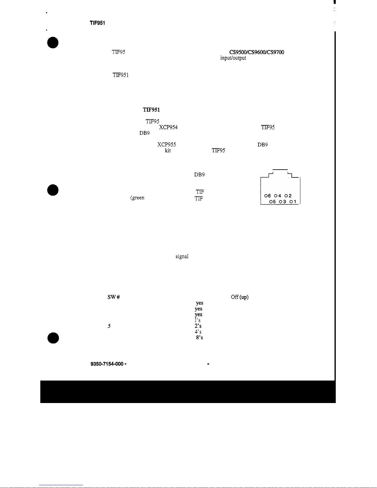
adapter, the wiring is as follows (these adapters are readily available from companies which sell
computer wiring accessories):
RJll
DB9
1
(blue)
2
Data
-
2
(yellow)
8
TIF
input
+
4 (red)
5
TIF
output
-
5
(black)
7
TIF
input
-
6 (white)
1 Data
+
3
(green 4
TIF
output
+
RJ
11
SOCKET
(FEMALE)
*
Note, twist the wires, white with blue, black
with
yellow, red with green
2.1 DIP Switch Settings
The rear panel DIP switch contains switches to configure the most often changed options. These
include auto answer mode, ring
signal mode, password mode, intercom port address (key panel
number), and baud rate.
2.1.1
Rear
panel DIP Switch #1:
DIP switch 1 (rear panel) settings:
Auto Answer
Generate Ring Signal
Password Required
Address
Address
Address
Address
Baud Rate
9350-7154-000 - Rev
B
On (down)
Yes
Yes
Yes
1's
2's
4's
8's
76800
Page - 1
Off
(UP)
no
no
no
9600
Telex
Communications, Inc.
Page 6
TIF951 Operation Guide
RTS Systems Division
DIP switch
1,
address
settings:
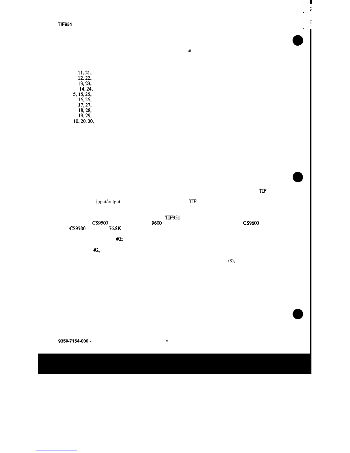
Address Settings: Rear DIP Switch, Switch # (down is on, up is
off)
Port Number
1,
11,21,
etc
2, 12,22,
etc
3, 13,23,
etc
4, 14,24,
etc
5,15,25,
etc
6,
16,26,
etc
7, 17,27,
etc
8,
18,28,
etc
9, 19,29,
etc
10,20,30,
etc
4
on
Off
on
Off
on
Off
on
off
on
Off
5
6 7
Off
on
on
Off
Off
on
on
Off
Off
on
Off
Off
Off
on
on
on
on
Off
Off
Off
off
off
Off
Off
Off
Off
Off
on
on
on
AUTO
ANSWER
mode will set the unit to answer the phone automatically when it rings. The number
of rings required before it answers is set on internal DIP switch
#2.
If
set for manual answer, the line
will
ring until someone at a key panel answers the call.
GENERATE
RING
SIGNAL
sets the unit
so
that when the phone line is ringing, certain designated
key panels or circuits will receive an audible ring signal.
PASSWORD REQUIRED
sets the unit
so
that when a call is automatically answered, it will require
that the user enter a password via DTMF before the unit will allow communications. The actual
password is set using internal DIP switch
#3.
PORT ADDRESS
tells the unit and the intercom which matrix inputs and outputs belong to the
TIF.
The settings are the same
as
for a key panel. The setting is the binary representation of the last digit
of the matrix
input/output number which that channel
of
the
TIF
is connected. See the address table
above for the actual settings.
BAUD
RATE
sets the data rate with which the
TIF951
communicates with the intercom. The data
rate for all
CS9500
intercom matrices is
9600
BPS
(switch
off).
The
data
rate for all
CS9600
and
CS9700
matrices is
76.8K BPS
(switch on).
2.1.2
Internal DIP switch
a:
DIP switch
#2,
which is located internally to the unit sets the number of rings before the unit auto
answers. Please note that the ring count is approximate.
This
switch has no effect unless the rear panel
DIP
switch is set for auto answer mode.
If
the ring count is set for a high number
(8),
and auto answer
is enabled, the unit may be used for mixed mode operation, where key panel operators normally answer
the incoming call, but the line will auto answer in the event they are away from their panels.
9350-7154-000 - Rev
B
Page - 2
Telex Communications, Inc.
Page 7
TIF951 Operation Guide
RTS
Systems Division
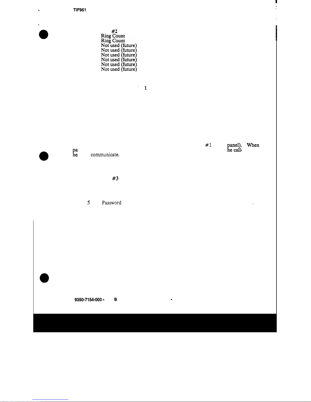
DIP Switch
#2
(internal):
1
2
3
4
5
6
7
8
DIP Switch
#2,
Ring Count settings
Rings Internal
DIP
SW2,
Switch # (down is
on,
up
is
off)
‘1
2
1
2
4
8
off
off
on
off
off on
on
on
2.1.3 . Internal DIP switch
#3:
DIP switch
#3,
which is located internally to the unit selects the password. It has
no
effect
unless password required has been enabled
on
DIP switch
#1
(rear
assword required is enabled, the password must be entered
via
DTMF
by t iane1)* e caller before
When
[e
may communicate. This is to prevent unauthorized use
of
the intercom by callers.
Switches
7
and 8 select the length of the password, from 1 digit to 4 digits.
If
set for 1 digit,
only the first digit
of
the password
is
used,
if
set for 2 digits, then the first 2 digits are used
etc.
DIP Switch
#3
(internal):
1
Password select
2
Password select
3
Password select
4
Password select
5
Password
select
I
6
Password select
7
Password length
8
Password length
9350-7154-000 - Rev
6
Page - 3 Telex Communications, Inc.
Page 8
TIF951 Operation Guide
RTS
Systems Division
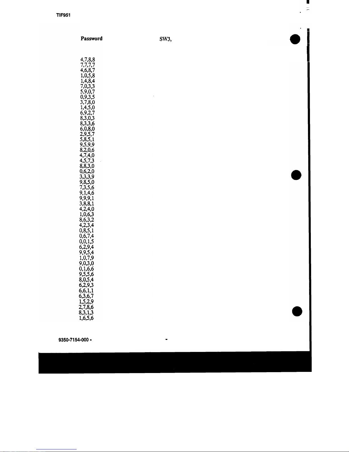
DIP Switch
#3,
Password settings
Internal DIP
SW3,
Switch
#
1
Off
on
off
on
off
on
Off
on
Off
on
Off
on
Off
on
Off
on
Off
on
Off
on
Off
on
Off
on
Off
on
off
on
off
on
Off
on
Off
on
Off
on
Off
on
Off
on
Off
on
Off
on
Off
on
Off
on
Off
2
Off
off
on
on
off
Off
on
on
Off
off
on
on
Off
Off
on
on
Off
Off
on
on
Off
Off
on
on
Off
Off
on
on
Off
Off
on
on
Off
off
on
on
Off
Off
on
on
Off
Off
on
on
Off
Off
on
on
Off
3
Off
Off
Off
Off
on
on
on
on
off
Off
Off
Off
on
on
on
on
Off
Off
Off
Off
on
on
on
on
Off
Off
Off
Off
on
on
on
on
Off
Off
Off
Off
on
on
on
on
Off
Off
Off
Off
on
on
on
on
Off
4
Off
Off
Off
Off
Off
off
Off
Off
on
on
on
on
on
on
on
on
Off
Off
Off
Off
Off
Off
Off
Off
on
on
on
on
on
on
on
on
Off
Off
Off
Off
Off
Off
Off
Off
on
on
on
on
on
on
on
on
Off
5
Off
Off
Off
Off
Off
Off
Off
Off
Off
Off
Off
Off
Off
Off
Off
Off
on
on
on
on
on
on
on
on
on
on
on
on
on
on
on
on
Off
Off
Off
Off
Off
Off
Off
Off
Off
Off
Off
Off
Off
Off
Off
Off
Off
6
Off
Off
Off
Off
Off
Off
Off
Off
off
Off
Off
Off
Off
Off
Off
Off
Off
Off
Off
Off
Off
Off
Off
Off
off
Off
Off
Off
off
Off
Off
Off
on
on
on
on
on
on
on
on
on
on
on
on
on
on
on
on
on
9350-7154-000 - Rev
B
Page
-
4
Telex Communications, Inc.
Page 9

TlF951 Operation Guide
DIP Switch #3. Password settings. continued
RTS Systems Division
1
on
off
on
Off
on
Off
on
Off
on
Off
on
Off
on
Off
on
--,
~~
Internal DIP SW3: Switch
#
2 3
4
off
off off
on
off
off
on
off off
off
on
off
off
on
off
on
on
off
on on off
off
off
on
off
.
off
on
on
off on
on
off
on
off
on
on
off
on on
on on on
on
on on
5
Off
Off
Off
Off
Off
Off
Off
Off
Off
Off
Off
Off
off
Off
off
6
on
on
on
on
on
on
on
on
on
on
on
on
on
on
on
DIP Switch #3, Password Length
Internal DIP SW3 Switch
#
Length
7
8
4
3
2
1
off
off
on
off
off . on
on on
SECTION
3, OPERATION
3.1 OPERATION
FROM A KEY
PANEL
The
TIF951
is operated from the intercom key panels, and from the
dial
pad
on
the
telephone at the remote end of the line. Any key panel with
a
key pad may use
a
TIF951.
All that is necessq
is
to program a
key
to talk to
the
TIF951,
as
if
it were a key panel.
The alpha numeric display or tally LED for that key then provides information about the
phone line.
A
solid display or non illumined LED indicates
a
line
which
is
not
in
use.
A
slow flash indicates a hne which
is
in
use
(off
hook). A rapidl
flashixl~
display
or
LED
indicates a line which
is
M
g.
In
addition, the alpha numeric &play
wd
display digits
as
they are dialed, and the LE
f.?
will
flash
for each digt.
3.1.1 Programming a key
to
use
the
"951.
To
use the
TIF951,
either to answer a call, or to call out, you
first
need to program a key
to
talk to the
TIF951.
This
is
accomplished
in
the same manner
as
pro
ammine
a
ke to talk
to
a
key
anel.
To
program a key by port number, enter
NUM-nnn-
GM-t,
where
hJM
is
the num er 1 key,
nnn
is
the port number
of
the
TIF951
you
want
to
use,
and t
is
any
talk
!
F
9350-7154-000 - Rev
B
Page
-
5
Telex Communications, Inc.
Page 10
TIF951 Operation Guide RTS Systems Division
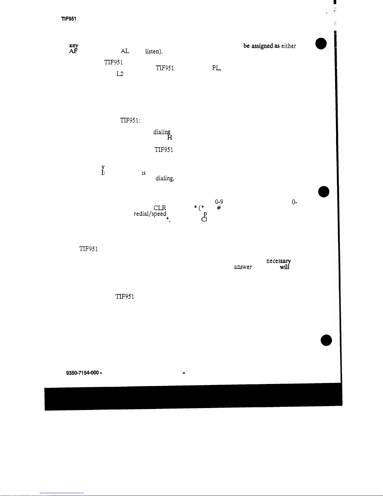
ke
.
In
general, you will
also
need to use the listen
key,
S
O
it should be assigned
as
either
d
(auto follow), or
AL
(auto listen).
Note that the TIF951 only responds to commands which are sent via a point to point key
assignment.
If
you wish to
use
the
TIF951
primarily on a
PL,
you must add a point to point
assignment
as
the
L2
talk assignment on the talk key for any panels which are going to
either answer the line, or dial out on the line.
3.1.2
Dialing
a
call:
Any key panel may dial calls on the TIF-951.
To
dial a call on the
TIF951:
1.
Turn
on the listen key for the line you wish
to
dial
on.
This
will
allow you to hear
dial tone, and your
DTMF
dialin tones.
2.
Enter dial mode by entering P
w
ONE-PGM-T.
PHONE
is
the 4 button
on
the
keypad. PGM is the red PGM key
on
the key pad, and
T
is
the talk key which
is
programmed to talk to the "IF951 you
are
dialing
on.
Leave the talk key
in
the up
engaged position
as
you dial the number.
3.
Dial the number.
As
you enter each digit, it will appear
in
the
alpha display above
the ke you
are
dialing
on.
On
panels with
LED
tally,
the
LED
will
flash
on
each
digit.
P
f
the listen key
IS
engaged, you will hear each
DTMF
tone
as
it
is
generated.
4.
When you have completed dlaling, momentarily disengage the talk key
to
exit dial
mode. The alpha numeric display will revert to
normal,
and you may use the key
and key pad in the normal manner.
Note: The key pad is used in the
usual
way. Digits
0-9
generate the
DTMF
digits
0-
9.
PGM generates
#,
and CLR generates
*
(*
and
#
are
displayed for these keys).
If
the last number redial/speed dial option
is
resent,
it
is
necessary to press
CLR
twice
if
you wish to generate a
*,
as
a
single
CF
LR is used to trigger the speed dial
and redial features.
3.1.3
Hanging
up:
The TIF951 will detect that the caller at the
far
end has hung up under most circumstances.
It detects the hang up by either loop interrupt, battery reversal, or the presence
of
dial
tone. Some telephone systems do not provide any
of
the above,
so
it
will
be necess to
force a hang up.
In
addition, if the call
was
placed to an auto answer device, it 3 be
necessary
to
force a hang
up
when the
call
is
complete.
Enter PHONE
-
CLR-t, where
PHONE
is
the 4 button
on
the
key
pa4
0
is
the
0
button, PGM
is
the red
PGM
button, and
t
is
the talk key which
is
programmed to
talk
to the
'IF951
which you
wish
to
hang
up.
This
will
disconnect the line for
which you struck the
talk
key.
Note that if the talk
key
is in
the
on
position, you must
turn
off
the key, then
momentarily turn it on again to indicate which
line
you wish
to
disconnect.
If
the
line is in dialing mode, then you must first exit dialing mode by
turning
off
the key,
then use PHONE-CLR-t
to
hang up.
9350-7154-000
-
Rev
B
Page
-
6
Telex Communications, Inc.
Page 11
TIF951 Operation Guide
RTS Systems Division
3.1.4
Re-dialing the last number:
The TIF951 remembers the last number which it has dialed.
1.
Enter dialing mode
by
following the instructions for dialing a
call.
2.
Enter
CLR-0-0.
The
TIF
will automatically redial the last number it dialed.
3.
Momentarily release the talk key to exit dialing mode.
Note that the number is remembered on a phone line by phone
line
basis. When the last
number redial command is issued, you
will
get the last number dialed on that TIF951
channel, regardless of which key panel dialed the number.
For
example,
if
you have a call
to 818-566-6700 on channel
1
of the
TIF,
and a call to 201-891-6002
on
the other channel,
and you are disconnected, issuing the redial command
will
re-establish the calls on the
same channels. The redial command may be issued
from
any key panel in the intercom,
not just the key panel that originally dialed the calls.
3.1.5
Dialing a Speed Dial number (stored number):
The TIF951 has
32
internal memories for storing frequently used phone numbers.
To
dial
one of these numbers:
1.
Enter dial mode.
2.
CLR-M
where
CLR
is the clear button
on
the key pad, and
M
is
two
digits, wlich
3.
Momentarily release the talk key to exit dialing mode.
are the speed dial code.
3.1.6
Storing a speed dial number:
1.
After dialing the number the usual way, enter the
CLR-PGM-nn
before .you release
2.
Momentarily release the talk key to exit dialing mode.
the talk key to exit dialing mode.
Note:
To
generate a pause during auto dial, enter *99.
This
is
used for example if
you need to enter
a
digit to get an outside line, and your phone system requires a
pause before continuing to dial.
Each number may contain
up
to
30
digits. Note that the memory for the stored numbers
is
RAM
in
the
TIF951.
The
numbers are unique to each TIF951 channel, and each TIF951
channel can have different numbers stored
in
it. If you plan
to
use the speed dial feature, it
is
advis,able to supply the TIF951 with
UPS
power, to prevent loosing the speed dial
information when
the
power fails.
9350-7154-000 - Rev
B
Page
-
7
Telex Communications, Inc.
Page 12
TIF951 Operation Guide RTS Systems Division
3.1.7
Answering
a
call:
1.
When a line
is
ringing, the alpha numeric display or
LED
above the talk
key
which
is programmed for that line will
flash
rapidly.
2.
To
answer the call, first
turn
on the listen key, then press the talk key and speak into
the microphone or headset.
3.
If
you have been programmed
as
a default station, your panel
will
"
ring
"
when ever
one of the lines rings.
If
you do not have a key already programmed, the
ringing
line
will a pear
on
your incoming call key (the key farthest to the right
on
the main
panelf:
To
answer, press
the
incoming call key and answer.
You
should copy the
key to main key position, either just before or just after you answer,
so
you can turn
on
the listen
key
to hear the caller audio.
3.2
TIF951
SYSTEM
SETUP
TO
RECEIVE
CALLS
To
the intercom system, the TIF951 is very much like a key anel.
I€
the phone lines are to
be used for outgoing calls only, then
no
programming in CS
k
DIT
is necessary. If users are
going to phone into the intercom from the outside, then the
TIF951 needs to be configured
to allow them to use the phone line in much the same way a local user
uses
his
key panel.
Programming information for the phone line is entered into the CSEDIT software just
as
if
the TIF951 were
an
ordinary key panel, by selectin 'Ke
s"
from the main menu, then
selecting the
TIF951 from the pick list of key panels.
he
AF951 o erates much the same
.
way
as
a key panel, except that the "keys" are really the D &buttons
on
the users
telephone.
32.1
Auto
Answer
Mode:
To
use the
TIF951
in auto answer mode, you must first enable auto answer mode on the
rear panel DIP switch, toggle number
1.
You
may
also
wish to enable Password required,
toggle number
3.
In addition, you may select the number
of
rings before the
unit
answers
(internal DIP switch
#2),
and the actual password (internal
DIP
switch
#3).
When the caller dials into the
TIF951,
he
will
hear the line ring, then the unit
will
answer,
and beep to request the pass word
(if
password re uired is enabled). The user then must
enter the password. The
-
unit
will
beep once to co
2
'rm a proper password.
If
the password
is not correct, the unit
will
beep twice
to
allow another
try.
Once the password has been entered, the
TIF951
will
establish communications
on
key
#1
automatically.
From
CSEDIT,
this
will
be talk and listen keys
#l.
If
for exam
le
the
user
were a camera operator, it
mi
ht be desirable to program the camera PL
as
ta%
and listen
on
talk and listen keys
#l.
if
the caller were a reporter, you might program
an
WE3
on
listen key
#1,
but
no
talk
on
talk key
#l.
Keys
2
to
7
may also be programmed.
To
use
the other
ke
s
from
the phone, just press the
DTMF
button for the
key
you
wish to use. For example, 2 key
#1
was
the camera PL, and
you
have
finished with the
shot,
you may press
#1,
which
will
toggle
off
key
1.
If
master
control were pro rammed on key
#2,
you
may then press 2 and
call
master control.
Likewise, you
mi&t have
an
IFB
programmed on listen
3,
with
no
talk.
If
you press
3,
ou
will hear
the
IFB.
#4
could have an
IFB
talk
on
it,
to allow a caller
to
speak on
an
P
Fl3
circuit.
Each DTMF button acts
as
if
it
were a push on/push
off
switch. When programming in
9350-7154-000 - Rev
B
Page
-
8
Telex Communications, Inc.
Page 13
TIF951 Operation Guide RTS Systems Division
CSEDIT,
just program the same key number
as
the number the user
is
going to press
on
the telephone to speak.
Talk
keys 8 to
15
have a special purpose.
If
you are not using auto answer mode, but have
set
u
the TIF951 to be manually answered, talk keys 8 to 15
will
be programmed for the
pane
P
s
which are to receive the ring signal. They may also be toggled
on
and off from the
phone by
DTMF
8,
so they may
be
used in auto answer mode
as
well.
You
may program
only key
8,
in which case it will behave the same
as
keys
1-7.
You
may also program
additional panels,
PL's,
IFB's etc on keys 9-15, and they
will
be activated simultaneously by
the
8
button on the phone.
3.2.2
Manual Answer Mode:
In manual answer mode,
the
line will ring until it is answered from a
key
panel. In general,
you must designate panels which are to receive the
"
ring",
so
they
can answer
the
line.
When
a
line is manually answered, the caller does not have to enter a password, even if the
password required switch is turned on.
You
may
mix
modes by enabling auto answer, but
setting
the
ring count for 8 rings. If no user has answered the call by 8 rings, the
TIF
will
then automatically answer the call, and if password required
is
also enabled, the call will be
screened by requiring a password.
To
use manual answer mode, you may choose to program keys 1 to
7
as
above
if
you wish.
When the phone is manually answered, key one will not be automatically activated, but the
caller may activate any of the keys if he wishes.
You
must also designate the panels which are going to ring when the line rings. Program
these panels on keys
8
to
15,
using both L1 and
I2
If
you have more than
8.
It is generally
not necessary to program the listen keys
on
these positions. When the line rings, the
TIF951 will "call" these panels when the line
is
ringing. When the
line
rings,
the
TIF951
generates a ringer noise which is then transmitted to these panels. The panels
will
display
the
TIF95l's alpha numeric
in
the incornin$ call window, and if a talk key has already been
programmed on the panel, it's alpha
numenc
will
flash rapidly.
3.3
Using the
TIF951
from
the telephone:
The TIF951 will behave differently depending on how it is programmed. It is up to the
operator who programs the
TIF951 to convey to the user what to expect.
If
the user is not
familiar with the operation of the
TIF951, it is best keep the operation
as
simple
as
possible, until they are familiar with
its
operation. For this reason, It is suggested that you
not use assword required unless you have had problems with nuisance calls
in
the past.
If
the
TIF
8
51
field user only requires one service, it is best to program that service on key
1,
enable auto answer, and disable password required. The telephone user
will
then only
have to dial the proper phone number to use the interface.
As
they become more familiar
with it's operation, you can then begin
to
offer more options to the
users,
or begin to
require a password.
In general, it is very easy to use,
if
the user has knows what to expect.
When calling in,
if
the unit
is
in
auto answer mode, it
will
answer the call after the number
of
rings whch have been selected.
If
assword required
is
not
enabled, the unit
will
indicate it
is
ready with a single beep. E password required
is
enabled, the TIF951 will
prompt for
a
password with 2 beeps. The user
will
enter the password, and the unit will
9350-7154-000 - Rev
B
Page - 9 Telex Communications, Inc.
Page 14
TIF951 Operation Guide
RTS
Systems Division
beep once if
the
password was correct, twice
was
wrong. The user
is
allowed 3 attem
ts
to
enter the password, after which the
TIF951
will
disconnect.
In
the event a user
Cass
the
TIF951
when the intercom system is either turned off or absent, the TIF951
will
answer
prompt
with
3
beeps.
Once the password is entered, the
TIF951 will enable
talk
and listen
on
key
1.
This should
be
pro rammed ahead of time to what ever communications the caller generally needs
first.
I
f
it is not desirable for the caller to be able to talk
at
this
point, then
only
the listen
key for key
1
should be programmed.
The caller may then either continue to use
key
1,
or he may
select
other keys with his
DTMF
pad. He may turn off key 1 by pressing
DTMF
1,
or may continue to just add other
keys. At any time, the caller may turn
off
all keys without hanging up
by
pressing
0.
When the call is complete, the caller should enter
*#,
which
will
cause the TIF951 to
disconnect. This
is
more reliable than waiting for the phone system to pass the disconnect
information to the
TIF951.
33.1
DTMF
codes
Once programmed
as
described in section
3.2,
the TIF951 may be o erated via the
DTMF
Touch Tonetm
key
pad
on
the telephone. The
DTMF
keys have the P ollowing
functions:
Normal
Mode:
1
thru
7
Toggle
on
and off talk and listen
#1
to
#7.
Note that initially,
#1
will
be enabled
if
the unit auto answered
the
line.
8
9
0
*1
thru
'7
*8
*#
To
e
on
and
off
talk and listen to the panels which ring when
the
T
'ne is ringing.
This
allows the caller to ''recall" the panels
without having to hang up and redial.
Togglmg this
on
will
allow
the callers voice
to
be heard from
all
the panels which
normally ring.
Enters programming mode, to reassign keys.
Turn
off
all talk and listen keys. Since
1-8
are
toggles, it
is
possible to forget which keys
are
"on"
and which
are
"
off".
In
this
case,
just press 0 to
turn
then
all
off,
and
start
over.
Toggle
on
and
off
listen
1-7.
By pressing * before the key, you
onl
chan e the listen.
This
allows
you
to listen
to
a
circuit
wi
Jaf
out t king to it, or
to
talk
to
a
mcuit without listening to
it. Note that you
will
automatically listen and talk to
#1
if
the
TIF951 auto answered the
line.
Toggle
on
and
off
listen for 8-15.
Disconnect.
This
will
cause the
TIF951
to hang
up.
It
is
a
good idea
to
do this before you hang up,
as
many phone
systems take
a
long time to
signal
that the
far
end has
hung
up.
9350-7154-000
-
Rev
6
Page - 10 Telex Communications, Inc.
Page 15
TIF951 Operation Guide
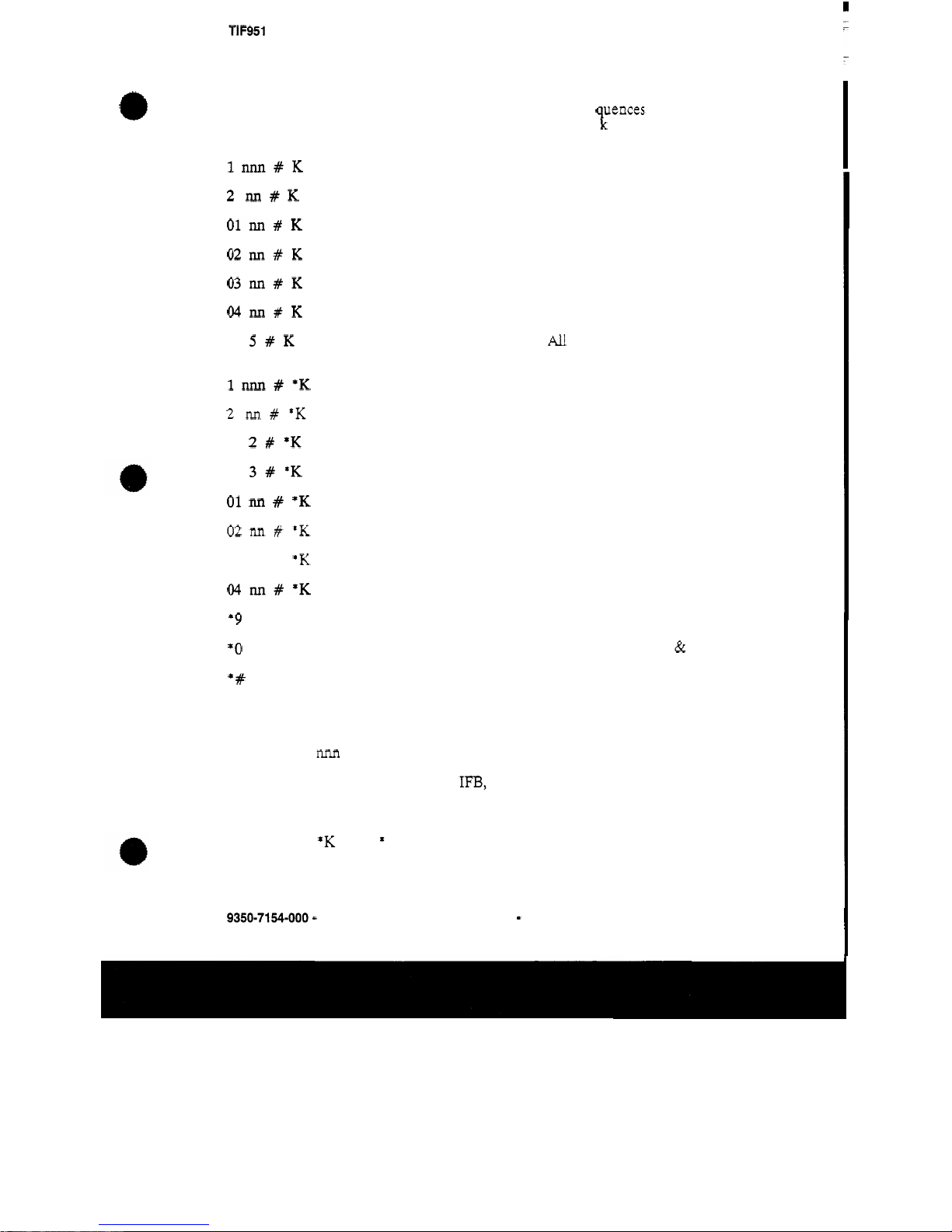
Programming Mode:
lnnn#K
2
M#K
01~#K
02M#K
03nn#K
WM#K
3
5#K
lnnn#*K
2
M#*K
3
2#*K
3
3#*K
01
M
#
*K
02
M
#
*K
03
M
#
*K
WIlXl#*K
*9
*O
*#
RTS Systems Division
You
may reprogram the talk and listen assignments on
1-7,
just
as
you can on a key panel
(if
they are not restricted via
CSEDIT).
Note that the se uences are the same
as
the
sequence you would use
from
a
‘fc
ey panel, except that you must
first enter programming mode by pressing
9.
Program a
talk
key to a point to point.
Program a talk key to a
PL.
Program a talk key to a special list.
Program a talk key to an
IFB.
Program a talk key to an
ISO.
Program a talk key to a Relay.
Program a
talk
key to
All
Call
(turns
on
the lower numbered
talk keys)
Program a listen key to a point to point.
Program a listen key to a
PL
Program a listen key to Auto Follow
Program a listen key to Auto Mute
Program a listen key to a special list.
Program a listen key to an
IFB.
Program a listen key to an
ISO.
Program a listen key
to
a Relay.
Exit
programming mode
Exit programing mode and turn
off
all
talk & listen.
Disconnect
Note:
0-9
are the number keys, * and # are
the
star and pound keys.
nnn
is three digits for a key panel number
M
is
two
digits, for an
IFB,
PL,
Relay, Special
List,
or
ISO.
K
is a key which you are programming,
just
press the digit
(1-7).
*K
is the * key followed by a digit
(1-7).
This
is
used to represent the listen
key.
9350-7154-000 - Rev
B
Page - 11 Telex Communications, Inc.
Page 16
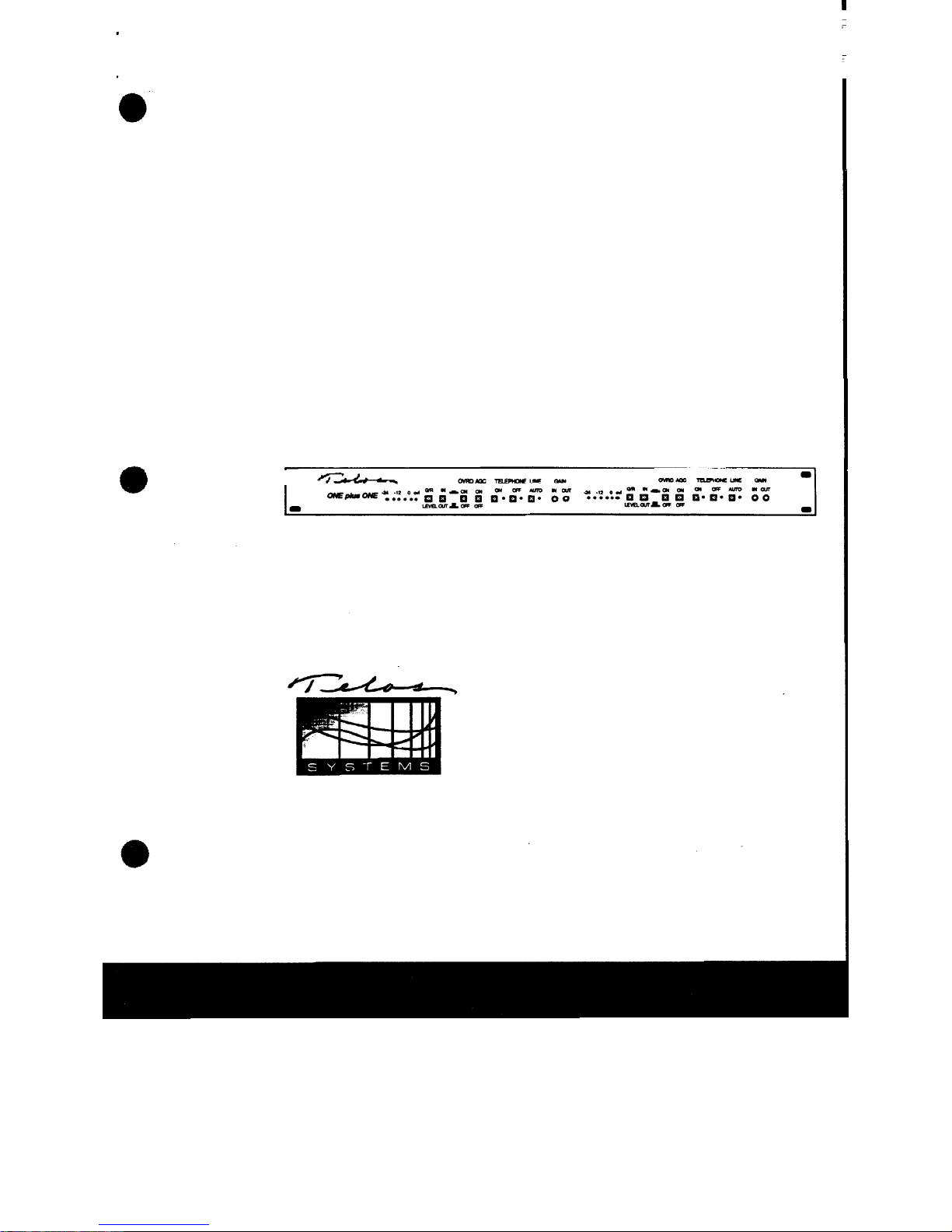
Telos
ONE
plus
ONE
Dual Digital Telephone Interface
User's
Manual
1.1
I'
Page 17
Telos Systems 2101 Superior Avenue Cleveland,
OH
441 14
(216) 241
-
7225 FAX: (216) 241-4103
0
Copyright 1991 by TLS Corporation
Page 18
.
..I
July
10,1989
A
personal
note:
You
have in your possession a remarkable piece of technology. The Telos One
does what would have been either impossible or impractical only a few years
ago. It relies on
digital signal processing,
a concept
known
to theorists for
years but only very recently available to
us
as
users.
It
is
entertaining to read the
signal
processing textbooks written
as
recently
as
the mid
70s.
The authors describe the state of the
art:
a
few seconds of audio
is
collected
and
processed with
FORTRAN
programs running on million dollar
mainframe computers. Only after minutes (or hours!) of expensive number
crunching did the expectant researchers get to
actually
hear
the brief audible
result.
About the same time,
yours
truly began
his
first
radio
station job. Using
phones on air was always a problem owing to the
familiar
shortcomings of
speakerphones and hybrids. Thus began what was to become many
years
of
tinkering with telephone interfacing. Nothing had worked
-
resulting in
discouragement having become firmly rooted when, in
1983,
articles describing
practical
real-fzme
DSP
began to appear in obscure
journals.
This
was made
possible by the introduction of
single-chip processors optimized for
use
in
manipulating analog
signals.
They cost
$350
-
but I sensed that their
availability signalled the beginning
of
a revolution. The next year and a
half
found me at work weekends and evenings learning the exciting new technology
and experimenting with telephone interfacing approaches using it. By late
1984,
the now famous Telos
10
was the result.
It had the singular virtue among available interface devices that it
acfually
worked.
At last
it
was possible to carry on a
natural
on-air conversation
without the common
up-cutting or distortion difficulties. We put it on the
air
at
WFBQ,
Indianapolis and made a few for
friends.
Slowly, the word spread.
Since
I
was happily employed
and
thus had no compelling interest in Telos'
economic success, it was only amusing
to
observe the digital hybrid technology
take the usual path of any new idea to eventual acceptance:
c
Page 19

It
wasignored
It
was
accused
(by
other interface
manufacturers)
Of
being
ineflecfive
It
was
accepted
by
users
with tolerance for
tisk
and
novelty
It
was
accepted
by
large
numbers
of
users
It
was
co-opted and copied!
For
a couple
of
years, Telos Systems was operated
as
a
sideline enterprise
while
I
continued to work
as
a
CE.
However,
as
is
now evident,
increasing
sales
caused Telos
to
grow beyond its "garage
"
origins
to become a bona-fide
broadcast manufacturer, adding staff, an office, phones, and
an
occasional ad.
I
finally
even
had
to quit my
job!
Our
research
continued and resulted
a
little
over a year ago
in
the
second
generation Telos
100
hybrid - which advanced the state
of
the
art
by
sigruficantly improving performance
and
taking advantage of
DSP
for the
dynamic processing
functions.
So
here we are
in
the present. The
work
of
the signal processing
theorists
for
decades (actually, centuries Fourier was at it a few hundred years ago!),
our
continuous work over the course
of
the
past
six
years, and the near-incredible
advances
in
digital audio and lowcost computing power have
combined
to
allow the creation
of
a result even
the
digital dreamers would have
been
shy
to predict a decade ago.
We
trust
you
wili
like
it.
Keep
on
keeping
the
GM
happy...
Steve Church
President
Page 20
I
User's Manual
V1.l
Telos
One
plus
ONE
Dual Digital Hybrid Telephone Interface
1
INTRODUCIlON
1
1.1
Overview
2
1.2
Specifications
6
2
INSTALLATION
7
2.1
Audio
9
2.2
Connection to the Telephone
Line
13
2.3
RemoteControl
13
2.4
Power
Source
14
3 OPERATION 15
3.1
Front Panel Controls
16
3.2
Metering and Level Adjustment
18
3.3
Feedbackcontrol
19
4
TECHNICAL DATA
and
TROUBLESHOOTING
21
4.1
Overview
22
4.2
Digital Section
25
4.2.1
Theory of Operation
25
4.2.2
Troubleshooting the Digital Section
26
4.3.1
Theory of Operation
26
4.3.2
Troubleshooting the Audio Section
27
4.3
Audio Section
26
4.4
Power Supply
27
4.5
IntemalConnections
28
Connector Pinout
Charts
31
Parts List
32
5
DRAWINGS 35
Signal Flow Block Diagrams
schematics
6
APPENDIX
Alternate Software Versions
Warranty and Application Caution
Power Supply Data Sheets
ACCESSORY
PCB
MODULES:
DTMF-to-ROTARY CONVERTER
BASIC AUTO
-
ANSWER
"
SUPER" AUTO-ANSWER
ELECIRONIC PHONE SYSTEM TUTORIAL
'0
Page 21

SECTION
1
INTRODUCTION
Page 22
1.1
OVERVIEW
The Telos
ONE
plus
ONE
Dual
Interface
The Telos
ONE
plus
ONE
consists of
two
Telos One digital hybrids
in
one
19
rack mount
enclosure.
The Telos One interface embodies a state of the art approach to
interfacing telephone
lines
for broadcast on-air, intercom interface,
or
teleconferencing use. The very fast and precise digital
automatic nulling hybrid allows smooth, natural, simultaneous
conversation without the
usual
speakerphone upcutting effect or
the audio distortion
and
feedback problems often experienced with
poorer hybrid
-
type interface devices.
As
well, a number of additional functions are accomplished in the
digital domain
in
order to enhance "real-world'' performance.
Included are sophisticated automatic gain control
in
both the send
and receive paths, a carefully
-
implemented override ducking
system, and a pitch shifter for feedback reduction.
Telephone connections
are
via standard modular jacks, while audio
input and output are connected via
XLRs.
Each hybrid
has
one
balanced input with provision for mic or line levels and
two
balanced outputs. The second output may
be
switched to
be
either a
second isolated output or a
mix
of the send and caller
signals.
Purpose
The purpose of the Telos One broadcast telephone hybrid
is
to
deliver
to
the receive output pure caller audio
with
as
little
of
the
send (announcer) audio
as
possible mixed-in. Until digital
signal
processing techniques were applied to the telephone interface
problem, there were
two
choices:
Switching.
The send and receive paths were separated by
having only one talk direction active at a time. The
common
"
speakerphones" use this approach. The
disadvantage
is
that natural conversation is impossible,
since the caller
is
cut-off when the announcer talks - and
vice
-
versa.
2
Tebs
ONE
plus
ONE
-
INlRODUCTION
Page 23
Analog
hybrids.
These were, on most phone lines,
very
poor at removing the send signal from the caller's audio.
This
meant that the announcer's voice would become
distorted
as
the phone audio was added to the
mix.
(A
full discussion of hybrids and interface systems
is
included in
the
Telos Telephone
Q
b
A.)
The Telos One is a
true digitul
second generation telephone
interface. It
uses
state-of-the-art digital techniques to perform
the hybrid function
-
the subtraction of the
send
from the receive
audio. The input and caller audio signals are converted to digital
.
and operated on in
such
a way
as
to very effectively remove the
send audio from the output while maintaining natural
simultaneous full
-
duplex conversation. The digital approach
assures consistently good trans
-
hybrid loss regardless of varying
phone
line
impedance.
Special Features
The Telos One incorporates sophisticated audio processing
in
the
digital domain
for
gain
control and filtering.
A
digital high-pass filter
is
used
to reduce hum and other low
frequency interference. High frequency noise above the telephone
frequency range
is
also
attenuated.
FREQUENCY
Te
ONE
plus
ON€
-
INTRODUCTION
3
Page 24
Smart
Digital
Automatic
Gain
control smooths input and output
levels.
A
noise-gate/downward expander
is
provided on the
receive path to reduce phone line noise during caller pauses.
A
switchable
mm*de
function
is
provided to allow ducking of
the caller while the announcer
is
speaking. The override function
includes an
acousfic
ducker
which dynarmcally reduces send audio
when caller audio
is
present
in
order to reduce feedback and aid
natural conversation.
Unique to the Telos One
is
a
special feedback reduction function
using a pitch
-
shifting approach. The input (send) audio
is
shifted
downward
in
frequency
by
4
Hz
to help prevent feedback build-up.
Front panel metering
is
provided for input level, output level,
and
gain
reduction.
Operation
When a call
is
initially established, a brief mute/adapt period
provides
an
opportunity for the system to set up to
the
line before
the
call
is
passed to the output. The caller hears a "noisy tone,
"
but none of
this
tone
is
heard at the output since the output
is
muted
during
this
time.
This
has
the incidental benefit of removing the
line switching
"
clunk." Adaption to the telephone line
characteristic continues
as
the conversation proceeds using voice
as
the driving
signal.
The
Hardware
The
process
of analog-to-digital and digital-to-analog conversion
is
critical to audio quality and hybrid performance.
In
the Telos
One,
IC
converters
called
CODECS
intended for telephone central
office application
are
employed. The
ICs
in the Telos One are
better than the usual telephone
CODECS
in that they use an
oversampling and digital filtering technique
for
the anti-aliasing
and
reconstruction filters rather
than
the usual mitched-capacitor
filter approach.
Thus
noise and distortion are quite
good.
Because the audio processing
functions
are performed in
the
digital
domain, the hardware design of the Telos One
is
quite simple.
Page 25

Multi-Line
Systems
Telos makes interface modules for multi-line switching. The
Direct Interface Module offers a convenient
and
flexible means to
switch up to
10
telco
lines
with provision for program-on-hold,
additional telephone sets for off
-
air conversation, etc. The
1A2
interface module is for use within a standard
1A2
key telephone
environment.
A
number
of
options
are available with regard to
interface methods, control panels, etc. Please contact
us
for details.
In addition, the
"
Super" Auto-Answer
PCB
module may be
configured
so
that the Telos One
may
be connected directly to
1A2-
style telephones with the telephone itself being
used
as
the line
selection device.
In some cases, the Telos One
may
be interfaced to "electronic
"
telephone systems. There
is
a tutorial on these phone systems
included later
in
this
manual which should be helpful to those
who wish to do this.
I
Te&
ONEPIUS
m~
-
IMRODUCTION
5
Page 26

1.2
SPECIFICATIONS
System
True digital.
Second
generation Texas
Instruments
TMS320C25
processor.
8
lcHz
sampling rate. Internal digital input and output
gain
processing, filtering.
Trans-hybrid
Loss
>40
dB with pink noise or voice
as
test input. Test set-up
as
specified
in our
Telephone Q6.A. All dynamic enhancement processing is
sm'tched
off.
With the ovemde and output expander
functions
switched-in, trans-hybrid
loss
is
enhanced by approximately 12 dB.
Send Level
to
Phone
Line
-
10 dBm average level. Maintained by intemal digital AGC.
Frequency Response
(caller
to
output)
200
-
3400
H
Z
+-1
dB.
Noise
and
Distortion
(caller
to
output)
Distortion:
c.5%
THD
+
N.
1
kHz;
caller
levels from
-
48
to
-
8
dBm.
Signal-to-Noise:
>60
dB.
Referred to
-
18
dBm phone Iwel. >72 dB
ref
to
0
dBm phone line level.
Send Audio
Input
XLR
female connector. Active balanced. Accommodates
-
24
to +12
dBm levels in
LINE
mode;
-
68
to
-
35
dBm in
MIC
mode. Front panel
screwdriver level adjust.
-;
Caller
Audio
Output
XLR
male connector. Active differential. Output levels to +14 dBm
depending upon der telephone
line
level and adjustment of front
panel level adjust. Will drive
60012.
AdMix
Output
XLR
male connector. Active differential.
In
AUX mode,
this
output
is
an
isolated second output.
In
MIX
mode,
this
is
a combined
send
and
caller output.
INPUT
to
MIX
Output
specifications:
Unity
gain;
44%
THD;
+12 dBm clip point.
6
Telos
ONEplus
ON€
-
INTRODUCTION
Page 27

INSTALLATION
SECTION 2
Page 28
8
T~IOS
ONE
PIUS
ONE
-
I
N
S
T
ALLATION
Page 29
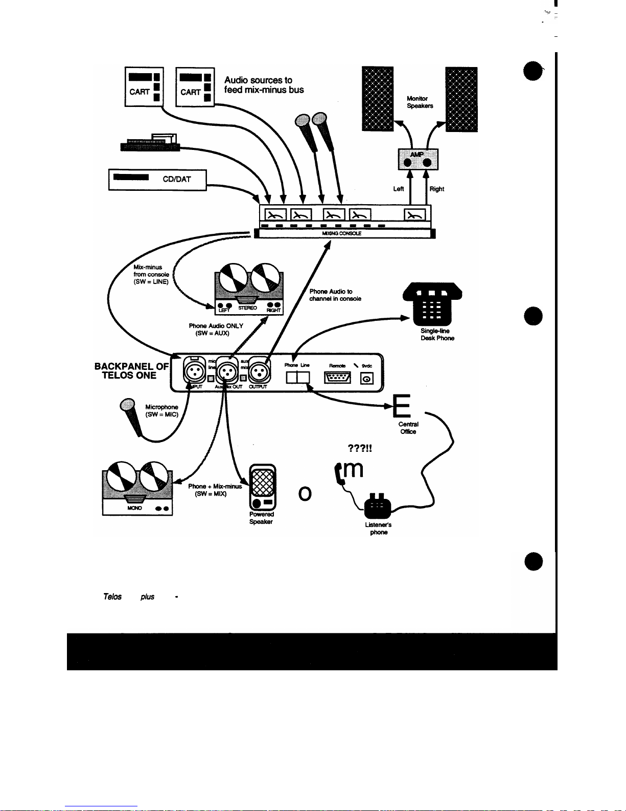
2.1
AUDIO
The drawing on the preceding page shows how the unit may be
incorporated into an on
-
air
studio
environment.
2.1.1
Mix-minus
The Telos One-plus-0ne send inputs should be fed
mix-minus
audio. That
is,
the
mix
of all the sources you want to feed the
phone
minus
the hybrid output itself.
Broadcast
Consoles
Most
modem broadcast consoles make some provision for
mix-
minus. The best allow selective feeds to the telephone system.
This
is
useful since you sometimes want only one mic feeding the
phone, sometimes you want three or four
mics
(during the morning
show, for instance), and sometimes you want to feed cart
machines
when callers need to hear and react to contest effects, etc.
User-Provided
Mix-Minus
For a simple installation, you can just take the patch send or pre
-
amp
output from the mic channel to feed the phone.
This
works
well, but doesn't have much flexibility. One approach which
allows more control
is
to
use
an
outboard mixer
to
combine sources
as
desired. All of the desired sources are paralleled into the on-air
board and the mixer and the mixer's output feeds the hybrid.
Tdos
ONEplus
ON€
-
INSTALLATION
9
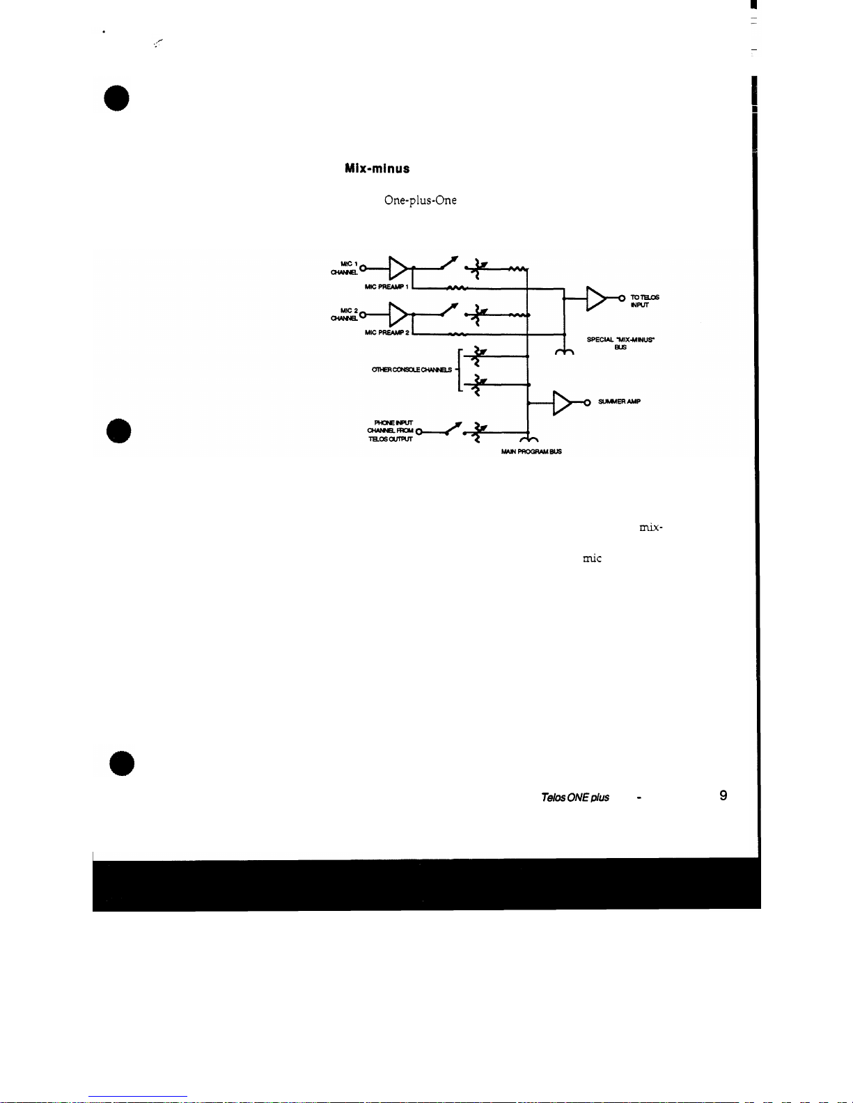
Page 30

Internal
Mix-Minus
in
the
ONE
plus
ON€
The
two
hybrids
in
the One-plus-One unit may be configured
so
that a single
mix-minus
feed may be
used
for both hybrids, with
each hybrid's output fed to the other's input
intetnnfly
ut
unity
gain.
Both hybrid
outputs
still
function independently.
The internal
mix-minus
cross-couples each
hybrid's
receive audio
to the other's input and
sums
the user-provided
mix-minus
to the
inputs. The user
mix-minus
must have
NO
hybrid audio
mixed
in
it. Five jumper pins are
located
on the connector board, marked
JP1.
Move
all
five jumpers from the
"
2
HYBRIDS
"
position to the
"MIX/MINUS"
position. Then feed your
mix-minus
to the
#1
hybrid input. The input to the
#2
hybrid
is
disabled. Both input
trimmers on
the
front panel function normally. The cross-coupled
hybrid audio
is
fixed
at
unity
gain,
relying
on the
output
AGC
to
keep levels
OK.
The block diagram below
and
schematics
should
help to make
all
of
this
clearer.
JUMPERS
SET
FOR
TWO
HYBRIDS
JUMPERS
SET
FOR
INTERNAL
MIXMINUS
Internal
Mix-Minus
Scheme
I
O
Telos
ONEPIUS
ONE
-
INSTAUATIOI'J
c
Page 31

A
Good
Idea
...
Here's a
useful
scheme for stations which do a lot of taping of calls
for later play
on
the air. The
mix-minus
goes into the left channel
of the studio tape
machhe, while the right channel gets fed
from
the hybrid output. The result
is
a two-track tape with the
announcer and caller audio separated. When you play back
on
the
air, you set the console input to mono and adjust the relative
balance as desired. You also have a tape which is easier to do
production from for contest squeals,
etc.
2.1.2
INPUT
AUDIO
CONNECTION
The input has the following characteristics:
Active balanced.
Approximately
2KR
impedance.
Pin
1
is
ground and pins
2
&
3
are the balanced audio inputs.
Unbalanced sources
may
be
used
by connecting pins
1 & 2
to the
source ground while the signal hot
is
connected to pin
3.
There
are
intemal jumpers
on
the hybrid board to select line or mic
level for the inputs.
On
HDR3
jumper pins
1 & 2
for line level;
jumper pins
2
&
3
for mic level. Be sure to move BOTH jumpers
when
changing
this
function.
LINE
LINE
MIC
MC
With
jumpers
set
to
LINE,
input level
is
-
24
to
+12
dBv
With
jumpers
set
to
MIC,
input level
is
-68
to
-
35
dBv
2.1.3
OUTPUT
AUDIO
CONNECTIONS
There are two separate and independent active differential audio
outputs each with the following characteristics:
Active balanced.
Telos
ON€p/us
ONE
-
INSTAUATION
1
1
Page 32

Output level
will
vary
from approximately
-
20
dBm to
+10
dBm
depending upon
gain
control adjustment, caller level and
whether or not the
AGC
is
engaged.
Pin
1
is
ground.
Pins
2
and
3
are
the balanced
signal
outputs.
If
an unbalanced output
is
required, connect between ground
and
either of the hot pins.
Do
not ground the unused hot pin.
Note
that
the
output
hl
meter
is
before
the
gain
control.
Main
Output
Caller audio appears on each of the
MAIN
outputs.
AWMIX
Output
The AUX/MIX output
is
either an extra isolated AUXilliary
output or a MIX of the send and caller signals.
Internal jumpers on the hybrid circuit board, on
HDR4,
select
which
of
the
modes
is
to be enabled. Jumper
pins
1
&
2
to
get the
AUX
function,
pins
2
&
3
for the
MIX
function.
MIX
MIX
pux
pux
AlJXNNON MIX
FUNCTK)N
When
in
the
MIX
mode, the input
is
passed to the
mix
output at
unity
gain. Note from the block diagram below that the pass
-
through gain
is
not
affected by the input or output
gain
controls.
However, since the output gain control
does
affect the caller level
in the
mixed
output, it
can
be
used
to adjust the balance between
the send and caller signals.
12
Teb
ONEplus
ONE
-
INSTALLATION
Page 33
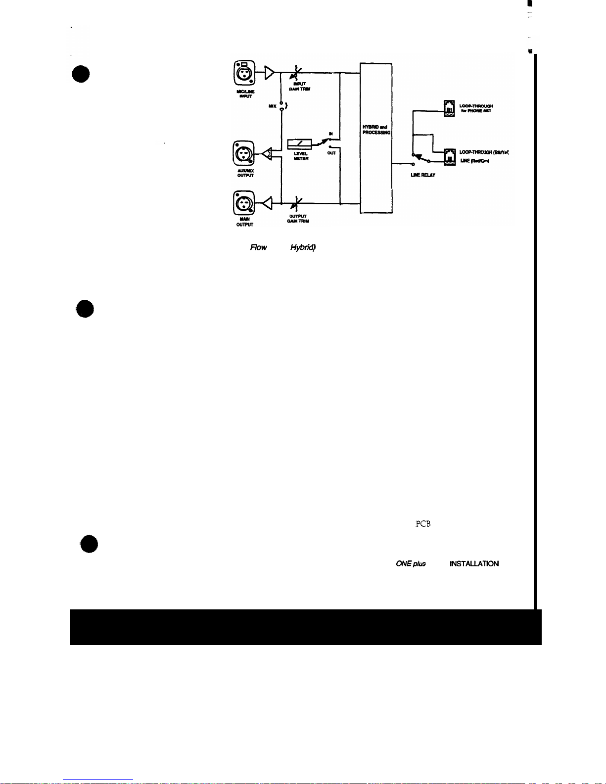
Audio Signal
Flow
(Each HNrid)
2.2
CONNECTION TO THE TELEPHONE LINE
LINE
and
PHONE
Modular
Jacks
Phone connections are made via the standard
modular
jacks on the
rear panel.
Each
LINE
jack is to be connected to
an
incoming central office
telephone line. The
two
center pins
(red
and green) are the Telco
connection, while the
two
outer
pins (black and yellow)
are
a loop
through connection which pass the phone line
through
when the
hybrid
is
not active.
Each
PHONE
jack provides another loop-through connection
which
also
passes
the phone line when the hybrid is not active. It
is
normally
used
for connection
of
a
desk
set
phone.
2.3
REMOTE CONTROL
Female DB15-type connectors on the rear panel provide access to
control functions.
This
connector's functionality and pin-out
depends upon whether the
"
Super" Auto-Answer
PCB
module
is
Telos
ONEplus
ONE
-
INSTAUATION
1
3
Page 34

3
2.4
installed. (When the
SAA
PCB
is
installed, the rear panel
DB15
is
internally connected to it, and
the
on/off commands and other
functions are
passed
to the hybrid from the
SAA
as
required.
When
the
SAA
is
not installed,
the
rear panel
DB15
goes
directly
to the hybrid.
Without the SAA installed,
OFF
and
ON
control requires a
momentary closure
to
ground. It
is
a standard
‘ITL
input pulled-up
with a
2.2
KR
resistor. Thus, it may be connected directly to
switches or
may
be
driven by
an
open collector or TIZ-compatible
logic output
as
desired.
If
the “Super” Auto-answer board
is
installed, refer to
its
manual
section for details on remote control operation.
rl
?EMOTE
CONTROL PINOUT/FUNCTION
IF
PLUGGED
TO SUPER
AA
PCB
-
1
2
3
4
5
6
7
0
9
10
11
12
13
14
15
-
AUTO
control
input
DROP control input
+5VDC
08 DTMF output
04
DTMF output
D2
DTMF output
Dl DTMF output
SCL
SEIZE control input
Digital Ground
tine
Mode
output
Auto
Mode
output
DTMF Data
Valid
n/C
SDA
POWER
INPUT
IF
DIRECT
TO
HYBRID
PCB
AUTO button
OFF (paralled
from
switch)
+SVDC
n/C
n/C
n/C
n/C
N.O.
A-lead contact
ON
(paralled
from
switch)
Digital Ground
A
-
lead wiper contact
AUTO
LED
n/C
n/C
N.C
A-lead contact
The
ONE
plus
ONE
uses
a universal input switching power supply
which accepts
AC
input at either
50/60
Hz,
from
90
to
260
volts
without any user selection being required.
The line
fuse
is
located on the supply
PCB.
14
Teios
ONEplus
ONE
-
INSTALIATiON
Page 35

OPERATION
SECTION
3
Page 36
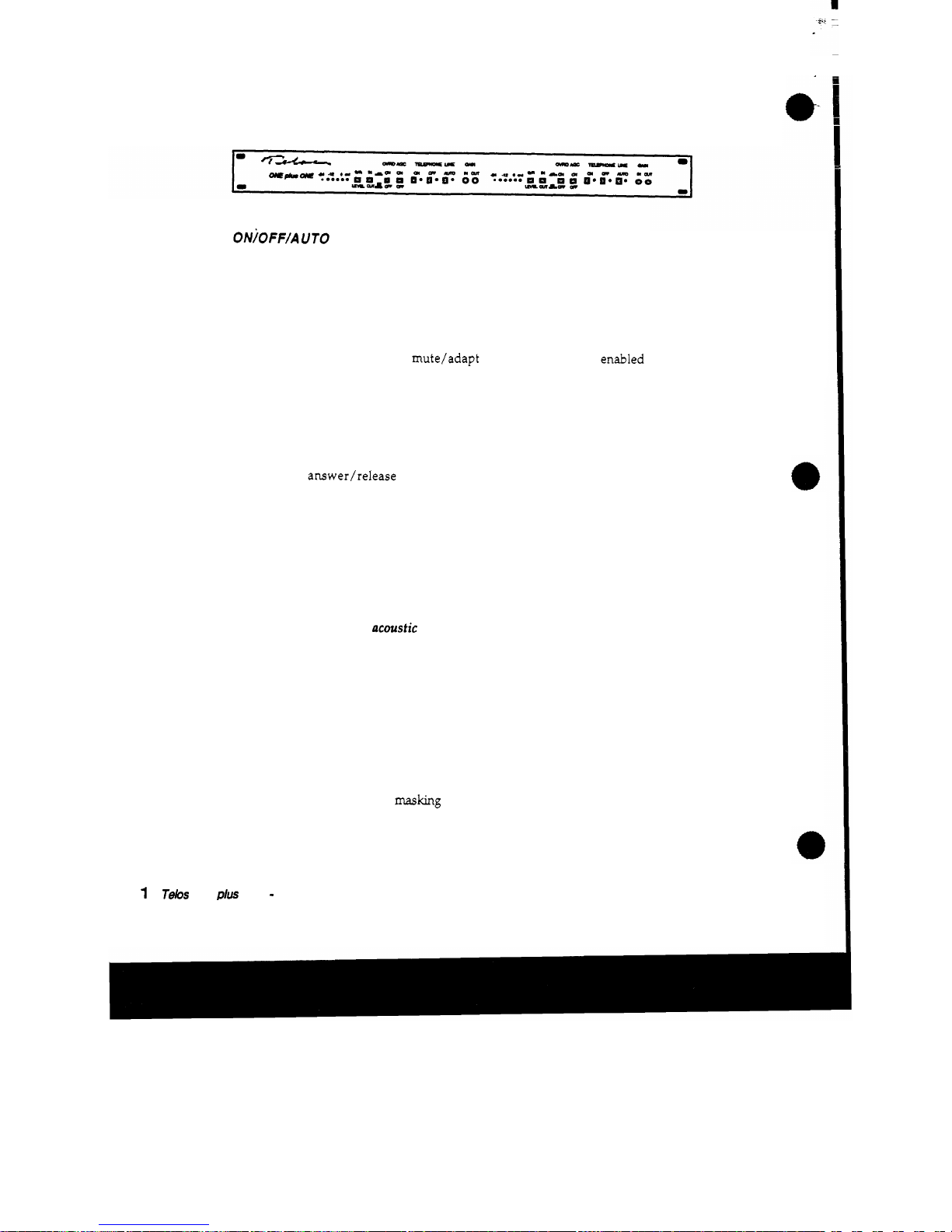
3.1
FRONT
PANEL
CONTROLS
ONjOFF/AUTO
Pushbuttons
When the
ON
button
is
pressed, the phone line
is
seized
and the
system sends a burst
of
white noise down the line, allowing the
hybrid to adapt to the phone line prior to the
start
of
conversation.
During
this
time, the outputs
are
muted.
At the conclusion of the
mute/adapt period, the output
is
enabled
and the conversation
may
proceed.
When the
OFF
button
is
pressed, the phone line
is
released.
The
AUTO
button
is
a momentary button that, when a "Super"
Auto
-
answer board
is
installed, toggles
the
unit
in
and out
of
the
auto
answer/release mode. Its accompanying
LED
indicator
illuminates when in
auto
mode.
(If
the
"Super" Auto-answer board
is
not installed, this button and
LED
is
brought to the rear panel
remote connector and may be used for any desired external
function.)
Output Processing: Override
This
pushbutton engages
two
independent
functions:
the
culler
ducking
and the
acoustic
ducking
function. In most broadcast
applications, you will find that engaging the override function
results in better overall performance.
Caller
Ducking
This
function operates in
the
caller audio path. When active,
there
is
approximately 6 dB
of
ducking applied to the caller audio
when
the
announcer speaks. However, very little change
in
caller
level will be noticed due to the very high speed operation
of
the
duck function and the
masking
provided by the presence
of
the
send
audio.
I
6
T&s
ONE
PIUS
ONE
-
OPERATION
Page 37
The purpose of
this
function
is
twofold
Aesthetic Preference.
Many air talents prefer the effect
of having some control over the caller when they speak.
lmprment
of "dynamic
"
Trans-hybrid
Loss.
Acoustic
Ducking
This
function operates
in
the send audio path. The acoustic ducker
works by reducing
the.send (announcer)
signal
dynamically when
the caller speaks.
The acoustic ducker
is
a
used to prevent feedback when open
speakers are being used to monitor callers.
Also,
since
an
open
monitor causes callers to hear themselves fed back
via
the acoustic
path
from
the speaker to the announce mic,
this
function has
the
additional benefit of allowing the caller to perceive a more
natural
sounding conversation.
The time constant
is
very fast,
so
the effect of the acoustic ducking
usually
is
not be noticed by the caller. The only disadvantage
might be that the announcer may
be
less able to break in
on
a caller
who
is
histing upon shouting
on.
Output
Processing:
AGC
The telephone dynamic
gain
processing
is.
enabled with this
pushbutton. The output processing includes both
an
automatic gain
control
and
a
smart
noise gate/downward
expander
function.
T&
ON€
p/us
ON€
-
OPERATION
1
?
Page 38
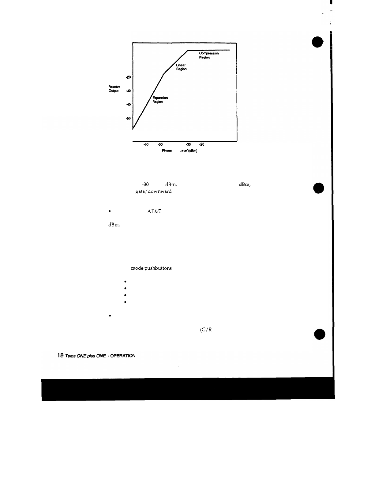
0
-
1
0
-20
ourput
-30
Relatii
Level
(dB)
40
"
I
I
-
70
-60
-50
40
-30
-20
-
10
0
Phcm
Line
Led
(dh)
As can be seen in the graph
which
shows the relationship between
telco line level and the Telos One output level, the AGC
maintains
a
constant output level when the phone
line
level vanes between
approximately
-30
and 0 dBm. Below approximately
-
48
dBm, a
gentle
noise
gate/downward expander operates to reduce residual
hybrid leakage and phone line noise.
According to AT&T statistical studies
of
the USA telephone
network, the average level found on standard phone lines
is
-
16
dBm.
In
O
U
T
experience high-volume "choke network" lines
generally have poorer levels.
3.2
METERING AND LEVEL ADJUSTMENT
The meter mode puihbuttons select the desired
function:
Input level
Input gain
reduction
Output level
Output
gain
reduction
The input level metering
is
after the input gain control. After
selecting
MIC
or
LINE
level, adjust the trimmer marked
"IN"
to
get
a
"0"
reading
on
the input level meter
(G/R
-
LEVEL
button out,
Page 39

IN-OUT
button in) while audio
is
present on the
INPUT.
Turning
this
trimmer up much past the
"0"
LED
rail2
nof
increase
the send level to the phone line due to the digital AGC!
Overdriving the input may result in distortion and very
poor
hybrid performance!
The output level meter
is
placed
before
the output gain control.
This
is
so
that the level may be adjusted to equipment downstream
The Telos' output level meter
(G/R
-
LEVEL
button out,
IN-OUT
button out) shows caller level. Adjust the trimmer marked
"
OUT
"
on the hybrid for a nod
(0
VU)
reading on your equipment while
audio
is
present on the phone line.
Dial
tone
is
OK
for
this,
but
keep in mind that dial tone level
is
about 6 dB hotter
than
voice.
Note:
When the AGC button
is
switched out, the meter reads the
telco line level and
thus
may
be
used to determine
if
there
is
a
phone line level problem. The meter's
OdB indication corresponds
to a phone line level of approximately
-
15
dBm.
3.3
FEEDBACK CONTROL
Sometimes,
even with the exceptional trans-hybrid
loss
produced
by the digital process, trouble with feedback may occur when the
system
is
being used with an open speaker. Generally,
this
happens only with poorer phone lines, or with very weak callers
requiring
lots of
gain
in the phone-to-speaker path.
Some
suggestions
for solution of
this
problem:
1.
Enable the Telos
OVERRIDE
function.
2
When mic processing
is
being
used,
connect the hybrid input in
such a way that it gets the
unprocessed
mic signal.
The
problem
here is that the mic processing combines with the internal Telos
input AGC to increase
gain
in the feedback path when no announcer
audio is present. Depending on the mic processor,
the
feedback
margin
could be reduced by many
dB.
The Telos intemal AGC
has
a
smart adaptive gate to prevent inappropriate
gain
increase, but it
is
thwarted by additional processing. If it
is
not possible to wire
around the processing,
try
to
set
the mic processing gate function
so
that the
gain
is
not "sucked-up" during pauses. You might
also
try
reducing the input level to the hybrid.
The
send level will still
be
OK,
since the AGC
has
considerable range, but the system won't
7elaS
ONE
@US
ONE
-
OPERATION
19
Page 40
have
as
much room to reach for
gain.
In
some difficult
cases,
it may
be desirable to disengage the Telos
oufpuf
AGC function since it
could reduce feedback
margin
in the same way input AGC does.
3.
Try
repositioning the
mics
and/or speaker. Of course, it also
helps to use
mics
and speakers that are directional. In typical
broadcast studio application.
EV
RE-20s
and
Shure
SM-7's
have
proven appropriate.
4.
Add equalization to the monitor path. Acoustic resonances
usually cause pronounced peaks in the
"
feedback response" of a
sound
system. Since
the
largest peaks generally
occur
at just a few
frequencies, reducing system gain at these frequencies with a
graphic
or
notch
EQ
helps tremendously.
5.
If
necessary, soften acoustic
reflections
in your studio by adding
curtains
or wall treatment.
The foregoing
is
intended to help in those situations where you
must
have an open speaker. Whenever possible, it
is
best to use
headphones to hear callers. When you have an
open
speaker, the
on
-
air phone audio
has
both a
direct
and
an acoustic path - from
the speaker to the announce
mic(s). Depending on the relative
levels, phone audio
quality
may
suffer.
Generally, the best scheme
is
to have the phone monitor speaker
mute when the mic
is
turned
on.
If
you have the announce mics
active to the phone system input even when the
mic
channel
is
switched off, the system can still
be
used
like a speakerphone
when taking
calls
off
the
air.
When
the call
is
to
be
used
on
air,
the announce
mike
is
on,
so
the speaker
is
muted.
20
Telos
ONEplus
ONE
-
OPERATlON
Page 41

SECTION
4
TECHNICAL DATA
and
TROUBLESHOOTING
Teb
ONE
plus
ONE
-
TECHNICAL
DATA
and
TROUBLESHOOTING
21
Page 42

kture of broadas
4.1
OVERVIEW
Philosophy
In the past few years, the
m
it engineering
has
changed considerably. At many stations, the engineering staff
has
been reduced
in
size and new responsibilities have been added. At
the same time, equipment has gotten more complicated and
specialized. Thus, many practitioners of the broadcast electronic
arts are forced to become
systems
engineers, emphasizing
equipment application rather than component-level trouble
-
shooting.
This
is
probably a positive development since it really would be
impossible for a station engineer to fully understand the internal
nuances of all the wonderful new high-tech stuff that
is
now
available to improve station operations! Also, as equipment
becomes more sophisticated and specialized,
stocking spare parts
for every eventuality has become difficult.
Thus, we don't really expect that much component-level
troubleshooting will occur.
So,
to support you when you need help,
we keep spare boards available for fast
overnight shipping.
In
most
cases,
we will swap boards with you at no cost. In the five
years since we introduced the Telos
10,
we have yet to charge for a
routine repair.
However, despite the comments above, we do provide full
schematics and component level troubleshooting information in
case you have the need or desire to tackle a repair (or
modification) yourself. Another reason we provide the
information
is
to
satisfy
your curiosity.
If
you are like me, you
probably just
have
to know what's happenin' inside the
fancy
box.
So
we tell you.
General Troubleshooting lnformatlon
CAUTION
The installation and servicing instructions
in
this
manual are
for
use
by
qualiied personnel
only.
To
avoid
electric
shock
do
not perform any
ser
-
vicing
other
than
that
contained
in
the
Operating
Instructions
Unless
you
are qualified
to
do
so.
Refer all servicing
to
qualifii service personnel.
Telos
ONEplus
ONE
-
TECHNICAL
DATA
and
TROUBLESHOOTING
23
Page 43

Access
to
the
PC
Boards
1)
The top cover
is
removed with a
1/16”
allen key.
This
will
expose all the circuit boards. Refer to the chart to identify the
various
PC
boards.
2)
The power supply and
AC
receptacle are covered by a
small
piece of clear plexiglass.
Do
not remove
this
protective cover or
place
your
fingers
under
it
unless
the ac plug
is
disconnected
from
the unit! When the cover
is
removed the power
supply
has
exposed live
surfaces!
If
the hybrid
PC
board
is
to be removed, continue
as
follows:
3)
Unscrew the four Phillips screws located near
each
comer of the
board.
If
a “Super” Auto-answer board
is
installed, unscrew
its
mounting hardware and gently lift it off the headers. A mounting
bushing
must
be
removed, too.
If
the rear panel
is
to be removed:
4)
Unscrew the
DB15
connector retaining stand-offs.
5)
The
six
XLR
connectors
have retaining screws
which
have to
be
turned
in
order to
be
released.
Do
this
as
illustrated below.
XLR CONNECTOR
RELEASE:
Insert a small screwdriver
intodtholes
in
the
connectors,
shown
3t right. Tumthe screwdriver
about
one
eighth
of
a
turn
counter
clockwise
to
release the connectors. A small s crewdriver
f
XLR
Release
Latches
such as
the
Xcelite
R3322
or
R3381y
need
to
be
filed down me
to
fit
the
s
lots.
Remember to retighten
the
XLR
latc
heswhen
replacing
the
Teios
ONE
PCB.
Thiswill ensure correct
support
for the
XlR
connectors on
the
PCB.
24
Teh
ONE
plus
ONE
-
TECHNICAL
DATA
and
TROUBLESHOOTING
Page 44

I
Desolden'ng
While we socket the
ICs
that have the greatest potential for
failure, most of the Telos One
ICs
are soldered
in.
That's because
most of the time the socket
is
more likely to cause trouble
than
the
IC.
This
is
of no consolation when one of
the
soldered
ICs
appears
to have failed.
When
you need
to
replace a soldered-in chip, the
right tool is essential. We
use
a vacuum desoldering system made
by Pace (the
MBT-100)
and
highly
recommend it. Cost
is
about
$450
-
worth it
if
you do much
PC
board troubleshooting work. The
only other real alternative
is
to clip the leads from the top
and
remove the solder from the holes with solder-wick. We've not
had much luck with the non-heated, manual vacuum desoldering
devices such
as
the one sold by Radio Shack We do not recommend
that newly soldered connections
be
defluxed.
Digital Signal Processing
Because the Telos
One
hybrid makes use of digital signal
processing for functions traditionally done in analog, the
hardware design of the hybrid
is
relatively uncomplicated and
straightforward. In many ways, the hardware is a
"textbook
implementation of a general-purpose processing system.
As
in
any
DSP
system, the input
signals
are passed through anti
aliasing low-pass filters to remove signal components above the
Nyquist frequency.
In
this
case,
the
Nyquist frequency
is
4
kHz
and
the ultimate sampling rate
is
8
kHz.
After
A/D
conversion, the signals
are
presented to the TMS320C25
DSP
processor, where software performs the hybrid and processing
functions.
Then,
the signals are converted back to analog and filtered to "re
-
construct" the desired analog audio.
Notation
Whenever a slash
( / )
is
used after a signal designation
in
the text
or on the
schematics,
an
active low
is
sipfled.
Teks
ONEplus
ON€
-
TECHNICAL
DATA
and
TROUBLESHOOTING
25
Page 45

4.2
DIGITAL
SECTION
4.2.1
THEORY
OF
OPERATION
The Processor and
Bus
'
(Refer to the Processor & 1/0
Logic Schematic in the DRAWINGS
section
of
this
manual.)
The
TMs32OC25
is
a specialized high-speed processor intended for
signal processing applications. Despite
its
unique properties, it
operates much like any other microcomputer from a hardware
standpoint.
Program store
is
provided by the
two
high-speed EPROM
(U2
&
U3).
These connect to the bus and are selected directly by the
32OC25's
assertion
of STRB/, PS/(Program Select/) , and R/(W/).
U6,
an
AC138,
provides the chip select signals decoded in the
usual
microprocessor way by expanding the lower address
lines.
CS7/
is
used
to trigger a watchdog timer,
U7,
at regular intervals.
If
processor operation should fail, the watchdog reacts by asserting
RES/ to the processor, thus restarting it. The watchdog also
provides a reliable reset when the
+5
V
power supply drops below
4.5
v.
U5
is
an output port
used
for the meter
as
well
as
for the control
input to the CODECS
U12
and
13.
U4
is
an input
port
which
is
used
to communicate button
status
to
the processor.
The CODECS have
logk outputs. One
of
these
is
used
to operate
the line and
"A"
relays as well
as
the
ON
and
OFF
LEDS.
Q1
provides current drive to the relay, while the appropriate
U11
sections drive the
LEDs.
CODEC
Interface
The CODECS are interfaced serially to the
32OC25
through its on
-
board serial port. Each CODEC
is
programmed to occupy a time
slot on the serial bus.
26
Teb
ONEplus
ON€
-
TECHNICAL
DATA
and
TROUBLESHOOTING
Page 46

Clock
and
Timing
4.2.2
4.3
4.3.1
The
timing
chain starts with a
40
MHz
clock oscillator module.
The
40
MHz
output
is
fed directly to
the
32ocL5. The HC390, U9
divides
the
40
MHz
to
2
MHz
in order to generate the CUR and
CLKX
signals
for
U1
and
the CODECS.
This
is
the data clock.
The
HC393 further divides the
signal
to
8
kHz
in order to generate
the Frame
-
Sync input to the
DSP
and CODECS.
TROUBLESHOOTING THE DlGlTAL SECTION
Check the power supply.
Check the
40
MHz
oscillator output and the divided-down clock
signals
to see that they
are
OK.
Unlike
TTL,
the CMOS logic ICs used in the Telos One Hybrid
should have a nice almost rail
-to-
rail
output.
Make sure that all of the required signals are getting to the
CODECS and that the CODECS are
outputting
data.
None of the logic section ICs should get hot,
so
if
any
is,
you've
found
the
problem.
On
rare occasions, a
CMOS
chip
may
latch up
and
get
hot,
but recover
and
work normally when power
is
removed
for awhile
and
restored.
Check
the
16
data
bus
lines
to
see
if
any are shorted. They should
all
exhibit lots of activity,
as
should
the
lower
address
bits.
AUDIO
SECTION
THEORY
OF
OPERATION
(Refer to the Block Diagram and the audio section schematic
in
the
DRAWINGS
section of
this
manual.)
The audio section
is
simple and straightforward. Everything
should be self
-
evident
from
the schematic.
Tebs
OFJEplus
ONE
-
TECHNICAL
DLTA
and
TROUBLESHOOTING
27
Page 47

U15, a 5532 opamp, provides an active hybrid function. One
section drives the phone line while the other
is
configured
as
a
differential amplifier in order to subtract some of the send audio
before the digital process completes the job. RF3
is
a special pi-
filter network
used
to remove
RF
interference.
The audio input section
uses
one
half
of U16, another 5532 op-amp.
This
is
a standard active differential configuration.
SW8
changes
gain
for either mic or line level inputs levels.
RF1
and
RF2
provide
RFI
filtering.
The other half of U16
is
used
in
a circuit which provides the
output
gain
control and a single pole of low-pass filtering for de
-
emphasis. (The pre-emphasis
is
a digital function provided
within CODEC
U13).
U17, another 5532 op-amp, provides the balanced output for the
AUX/MIX
output port. One section operates as a summing
amplifier;
one
of the summer inputs
is
always connected to the
hybrid output while the other
is
switched by
SW9
to either ground
or the input audio signal.
U14
is
a
special
purpose IC which
has
two
low-pass filter sections
as
well
as
a balanced
6ooR
line driver. The U14 line driver section
provides
the
main
audio output.
4.3.2
TROUBLESHOOTING THE AUDIO SECTION
Using a scope for signal tracing should do the
trick.
All chips
should
run
cool except for non-Signetics brand
5532s
-
if
is
nonnal
for
these
to
run
hot.
4.4
POWER
SUPPLY
The Telos ONE plus
ONE
uses a
4OW
+12W universal input
power supply. Refer to the appendix for manufacturer's data
sheet.
Each
circuit board that requires power locally regulates
the
+12VDC down
to
the required voltage.
Each
board
has
its own
regulators:
+5v
DIGITAL
Powers the processor and other digital
ICs.
Regulated by three-terminal regulator
VR3.
A
gold
cup,
C3,
holds up the power voltage in the event of a brief line voltage dip.
28
Teh
ONEplus
ON€
-
TECHNICAL
DATA
and
lROUBLESHOOTlNG
Page 48

+5v
ANALOG
Powers all the op-amps and the CODECS.
Regulated by
VR2.
-5v
ANALOG:
Powers op-amps and the CODECS.
Uses
U18,
a
switching inverter, in order to generate a negative voltage which
is
then regulated
by
VR1.
4.5
INTERNAL CONNECTIONS
[
%!E
8
Answer
Telos
ONE
Hybrid
11
%!E
Answer
Telos ONE
Hybrid
Telos ONE
plus
ONE circuit board and
connector identification diagram
T/R
The jacks marked
"T/R
are the "tip and
ring
"
of
the telephone
line.
A
fourconductor cable routes the
main
telco
and
loopthrough
signals
from the rear panel connector board
to
the hybrid.
If
the
DTMF-to
-
Rotary converter board
is
used,
the connector board cable
goes
to
the rearmost
RJll
jack on the converter board; the other
RJll
jack then
goes
to
the
hybrid. That
is,
the converter board
goes
Teb
ONE
p/us
ONE
-
TECHNICAL
DATA
and
TROUBLESHOOTlNG
29
Page 49
in
series
with
the phone line.
CONTROL
The connectors
marked
CONTROL
route various control signals
from the hybrid to the rear panel
15-pin D-sub connector.
This
cable
runs
from the connector board to the hybrid.
If
a "Super
"
auto-answer card is being used, the
CONTROL
cable on the
connector board
is
plugged to the "Super" auto-answer board's
connector.
YO
This
connector routes send audio to the DTMF-teRotary converter
board (for
DTMF
detection), the ON pin of the auto-answer card
(to mute the hybrid during rotary dialing),
+12VDC
and ground.
Not used
if
the converter board
is
absent.
AUDIO
SIGNALS
Route the audio input, output, aux/mix, mix-minus signals,
+12VDC
and ground
from
the connector
boards
XLRs
and power
supply connector.
+/-
This
is
the power supply connector.
+lZVDC
and ground are
brought to the rear panel connector board, which, in
turn,
distributes these signals to both hybrids via their respective
AUDIO SIGNALS connector.
30
Tebs
ONEplus
ON€
-
TECHNICAL
DATA
and
TROUBLESHOOTING
Page 50

52
to
P3,P4
REMOTE CONTROL PINOUT/FUNCTION
pin
ws
IF
PLUGGED
TO
SUPER
AA
FCB
I
IF
DIRECT
TO
HYBRID
PC0
2
14
13
13
11
12
9
11
7
10
5
9
3
8
16
7
14
6
12
5
10
4
8
3
6
2
4
1
4
10
7
9
AUTO control input
DROP control input
+5VDC
D8 DTMF output
~ ~~
AUTO button
OFF
(paralled from switch)
+5VDC
n/C
~~
D4
DTMF output
n/C
D2 DTMF output
n/C
Dl DTMF output
SCL
SEIZE control input
Digital Ground
Line
Mode
output
Auto
Mode
output
DTMF Data Valid
n/C
SDA
n/C
n/C
ON (paralled from switch)
Diqital Ground
n/C
AUTO LED
n/C
n/C
n/C
AUDIO SIGNALS
(J1
to
P1
.P21
'AUTO" button
'AUTO' LED indicator
+12VDC
+1
PVDC
GND
GND
output XLR pin 2
GND
output XLR pin
1
output XLR pin
3
d
11
12
13
14
15
16
17
19
-
la
2a
-
aux/mix XLR pin
3
aux/mix XLR pin 2
input XLR pin
3
aux/mix XLR pin
1
input XLR pin 1
input XLR pin 2
extrainput from
JP1
input to 'IN LVL" pot
extra output to
JP1
output of U16
in
7
P
UO
SIGNALS
to
decoder
board
(J4
to
J3,J4)
1
+12VDC
5
GND
4
GND
3
P1 pin 18 INput audio for DTMF converter chip
2
P3 pin
3
'ON' signal from Super Auto answer
board
Telos ONE plus ONE
Connector Cross
-
Connect and Function Directory
Telos
ONEplus
ON€
-
TECHNICAL
DATA
and
TROUBLESHOOTING
31
Page 51
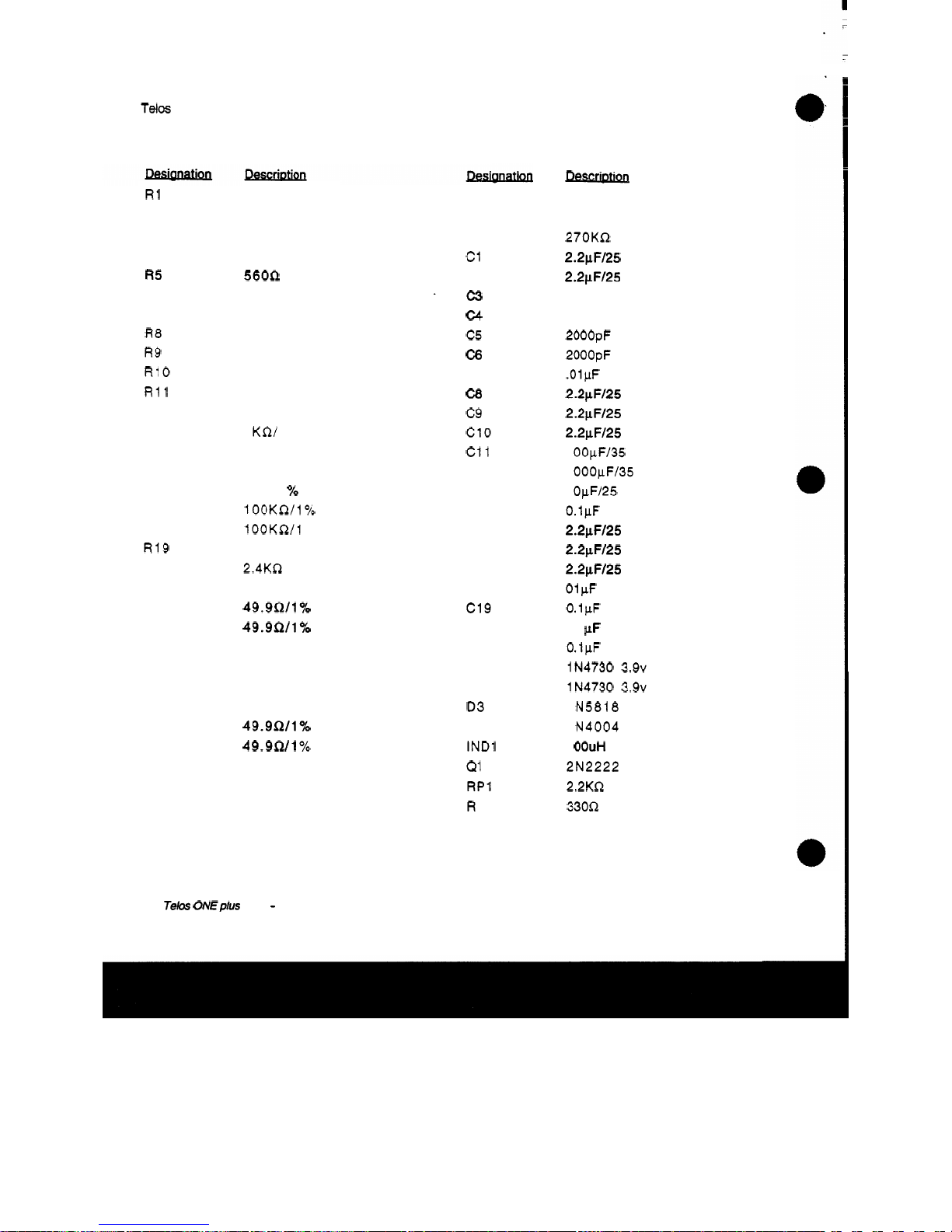
Tebs
One
plus
One
HYBRID
PARTS
LIST
R1
R2
R3
R4
R5
R6
R7
R8
R9
R10
R11
R12
R13
R14
R15
R16
R17
R18
R19
R20
R2 1
R22
R23
R24
R25
R26
R27
R28
R29
R30
R31
R32
1
OOR
1
OOR
1 OKR
1 KR
560R
1 OKR
1 OKR
1 OKR
1
OOR
33KR
1
OKR
1 OKR
1
KR/ 1
Yo
1 KR/ 1
Yo
1 KR/ 1
Yo
1 KR/ 1
%
lOOKR/l%
100KR/l
Yo
1 KR
2.4KR
1 OKR
49.9R/1%
49.9R/1%
1 OKR
56KR
1 KR
15KR
49.9!2/170
49.9R/1
70
1 OKR
1 OKR
1 OKR
R33
R34
R35
c1
c2
-c3
c4
c5
c6
c7
c8
c9
c10
c11
c12
C13
C14
C15
C16
C17
C18
c19
c20
c2 1
Dl
D2
03
D4
IND1
Q1
RP1
R
P2
Descr-
..
1
OKR
39KR
270KR
2.2pF/25
tant
2.2pFI25
tant
0.1
Farad Gold
Cap
22pF
mono
2000pF
mono
2000pF
mono
.OlpF
mono
2.2pF/25
tant
2.2vF/25
tant
2.2pF/25
tant
1 OOpF/35
electrolytic
1 OOOpFl35
electrolytic
1 OpF/25
tant
0.1pF
mono
2.2pF/25
tant
2.2pF/25
tant
2.2pF/25
tant
01pF
mono
0.1pF
mono
0.1
pF
mono
0.1pF
mono
1N4730 3.9~
zener
1N4730 3.9~
zener
1 N5818
1 N4004
1
OOuH
toroid
2N2222
2.2KR
SIP
33012 SIP
32
Telos
ON€p/us
ON€
-
TECHNICAL DATA
and
TROUBLESHOOTING
Page 52
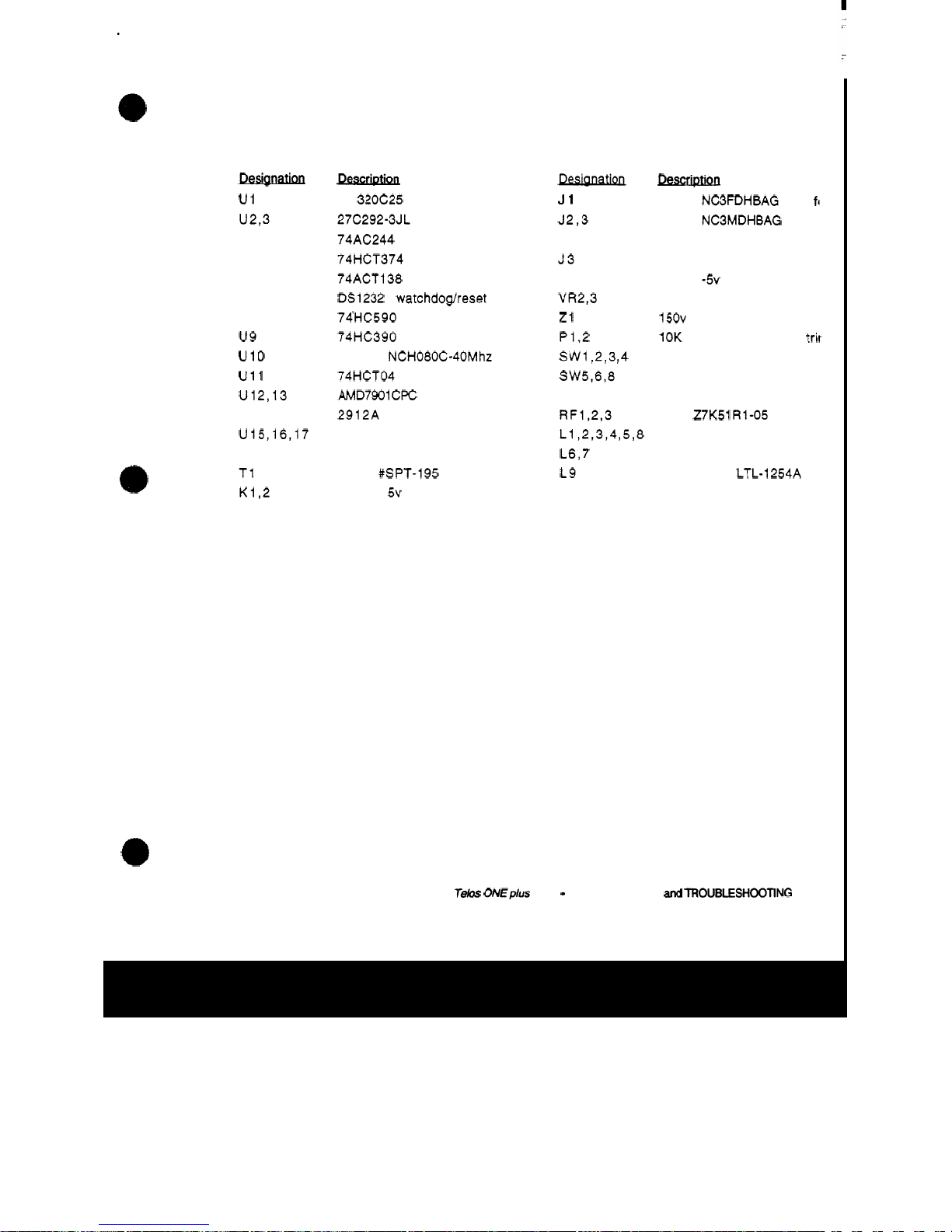
Telos One plus One
HYBRID
PARTS
LIST
continued
...
Deslanatlon
u1
U2,3
u4
u5
U6
u7
U8
u9
u10
u11
U12,13
U14
U15,16,17
U18
T1
K1,2
Descrlptuan
..
TI 320C25
27C292-3JL EPROM
74AC244
74HCT374
74ACT138
DS1232 watchdogheset
74HC590
74HC390
Saronix NCH080C-40Mhz osc
74HCT04
AMD7901CPC CODEC
2912A
5532 op-amp
MAX636 switching inverter
Prem
#SPT-195 xfmr
Omron
5v DIP relay
Pesianation
J1
J2,3
J4
53
VR
1
VR2,3
z1
P1,2
SW1,2,3,4
SW5,6,8
sw7
RF1,2,3
L1,2,3,4,5,8
L6,7
L9
DescriDtlon
Neutrik NC3FDHBAG
XLR
fr
Neutrik NC3MDHBAG XLR
I
DB15 female
modular phone receptacle
7905
-5v reg
7805 +5v reg
150v ZNR
10K rt angle multiturn trit
Alt action switch
Mom switch
Two pos DIP sw
TDK
Z7K51 R1-05 RF filte
Green LED LTL
-
1234A
Red LED LTL
-
1224A
Yellow LED
LTL-1254A
TeM
ONEPIUS
O
N
E
-
TECHNI
C
AL
DAT
A
and
TROUBLESHOOING
33
Page 53

DRAWINGS
SECTION
5
Te&
ONEplus
ONE
-
DRAWINGS
35
Page 54

DRAWINGS:
Hybrid Signal
Flow
Block Diagram
TMS320C25
Pinouts
Hybrid Digital Circuits Schematic
Connector Board Schematic
Hybrid Input and Output Audio Schematic
Hybrid Phone and Control Schematic
Page 55

AWYIX
-I
@
pfwcK
t
ousnc
ITE
NOSE
NERATOR
I
I
WE
Digital
Processing
Section
Telos
ONE
PLUS
ONE
Signal
Flow
Block
Diagram
Page 56
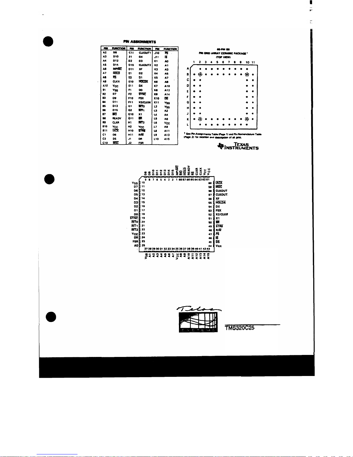
F
Telos
ONE
PLUS
ONE
TMS320C25
Pinouts
Page 57
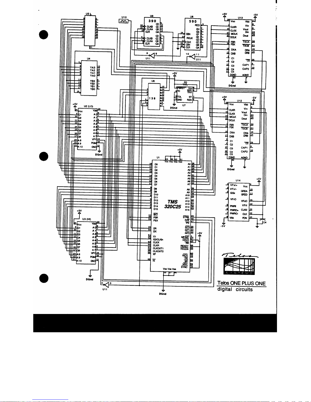
Page 58

INPUXLR
1
Jl
AUWMlX
XLR
152
cxnPul
XLR
1J3
RahE
1 J6
UN
INPUT
XLR
Ul
AUWMIX
XLR
22
OUTPLITXLR
2J3
RahE
2J6
UH
II
3l
2
.
-
/I
c
2
4
6
8
10
1
II
5-
60-
P1
P3
P5
P2
P4
P6
J
1
P7
'3
Telos
ONE
PLUS
ONE
,a
-
connector
board
Page 59

J1
41
I,
02
e,
J6
05
P1
(IN
LVL)
-
Telos
ONE
PLUS
ONE
input & output audio
Page 60

e
J3
e
HDRl
+5v
f
DATA
LINES
0-7
Tela
ONE
PLUS
ONE
phone & control
Page 61

APPENDIX
SECTION
6
Page 62

TELOS ONE
HYBRID:
ALTERNATE
SOFTWARE
VERSIONS
1
.x:
4.0:
4.x:
The Telos One
is
a "true" digital-signal-processing system. That
means that most system characteristics are fixed by the software
which
is
contained within
two
EPROM chips.
This
provides us
with the opportunity to change the hybrid's audio operation to
accommodate special or unique
cinrumstances by merely swapping
the
EPROMs.
A
number of special software versions have become more-or-less
standard.
This
are described below. There are, in addition, a few
more which have
been
developed for unusual applications.
If
you think you need special software, either the versions listed
below or something
really
different, please contact Telos.
Note:
If
we know
or
think that your hybrid
is
to
be
used
for
intercom interface applications, we automatically install version
4.X
soffware.
In
each case below, there
are
two
components to the version number.
The number before the decimal point
is
the series number and
defines the basic characteristic, while the portion after the
decimal point changes
as
improvements or minor changes are
implemented.
Normal Telos ONE operation
This
is the software normally shipped with Telos Ones. It
implements the operating characteristics described earlier
in
this
manual.
Bell Atlantic Teleconference Version
Has
limiter on
send
audio instead of AGC. Symmetrical ducking
with about
14
dB on each path. Best for making multi-line
conference bridges.
"ABC-TV Version
"
-
For Interfacing 4-Wire
Intercoms
Same
as
4.0
but provides 6 dB more send level.
Also,
ducking
modified somewhat
-
favors receive. Widely
used
with McCurdy,
Clearcom and other 4-wire intercom systems. Permits multiple
lines to be conferenced without feedback, etc. Telos has
c
Page 63

I
considerable experience in
this
area. Please
call
with your
special
requests
and
unusual
applications.
5.X:
The "Dallas" Version.
Developed in response to the very bad phone line conditions which
exist
in
the
Dallas/Fort
Worth
and Miami/Fort Lauderdale areas.
For some reason, these parts of the country have exceptionally bad
phone service. Levels
vary
over a
30
-
40
dB range and line
impedances are particularly difficult for the hybrid to
accommodate.
This
version adds more ducking
in
both directions,
increases the
AGC
action, lowers the receive expansion threshold,
.
and alters the adaptive hybrid parameters to effect better trade
-
offs for bad phone
lines.
Outside of
Dallas,
this
software
is
for people who:
1)
Prefer a more of "speakerphone
"
switching
effect.
2)
Prefer a more aggressive
AGC
action on the phone audio.
3)
Need to accommodate very poor phone
lines
with widely
4)
Have
open
monitor speakers and
are
having
trouble
with
varying levels.
feedback
When
the phone line impedance
is
very complex. The Telos
ONE'S
analog
hybrid then leaks too much during
send
audio, causing the
digital
hybrid to halt adaption. Version 5.x
software
can tolerate
more leakage, due to a change
in
one
of the adaption parameters.
Secondly, a
"
see-saw" ducking effect has been added. That
is,
the
ducking
occurs
on the send path during receive and
on
the receive
path during send. The level of the ducking
is
about 15
dB,
yet it
has a very fast recovery time and
is
biased more toward the
receive side. The full
-
duplex operation
is
not affected, just the
level
of
the ducking (about
6
dB
with standard software). The
expansion threshold level has been reduced
so
lower-level callers
don't get expanded down.
AII
this,
along with Telos' digital pitch
shifter and digital
AGC
helps the hybrid adapt better to poor
phone
lines.
6.X:
"
RTS Version
"
This
is
the preferred version for connecting
RTS
or other 2-wire
intercom system
to
the Telos
ONE
phone jack. Stays on
continuously.
A
change
in
the adapt threshold allows send level
to be increased with a resistor for
RTS
operation.
Page 64

WARRANTY
and Application Caution
The Telos One is warranted to
be
free from defects in material and
workmanship for a period of
365
days. Written notice of claim must
be received by seller within the warranty period. In the event of a
defect during the warranty period,
if
customer returns the defective
part
or
the Telos One to a place designated by the seller,
transportation prepaid, seller at
its
option, will either repair
or
replace
the part
or
the Telos One, anti such action
by
seller shall
be
the full
extent of seller's obligation hereunder. Seller will pay the
transportation charges to return the part
or
unit to the customer. Of
course, the warranty is void
if
the unit is subject to misuse, accident,
neglect
or
damage.
No
other warranties express
or
implied, all
of
which are specifically
excluded, including, but not limited to, the warranties
of
merchantability
or
fitness
for a particular purpose, shall
be
applicable
to any equipment sold hereunder, and the foregoing shall constitute
the sole right and remedy. In no event shall the seller
or
it's
agents
be liable for incidental
or
consequential damages, or
for
loss,
damage,
or
expense directly
or
indirectly arising from use of the
products, or any inability to use them either separate or in
combination with other equipment
or
materials,
or
from any other
cause.
The Telos One Interface is intended to
be
used
with
FCC
registered
protective interface devices.
Page 65
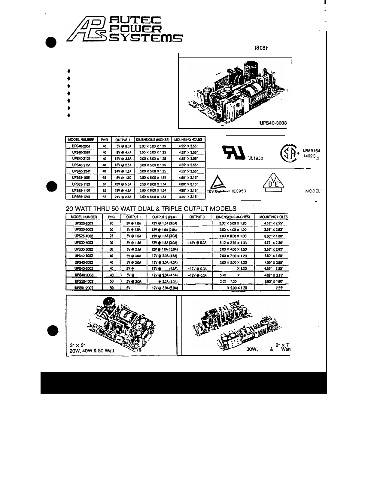
rn
RUT€:
POWER
SYSTErnS
@
9301-101
Jordan
Avenue,
Chatsworth,
CA
9131
1
Tel:
(818)
341-6123
Fax:
(818)
341-5726
WE
OFFER
...
+
High
Volume,
tow
Cost
Manufacturing.
+
90-260
VAC
(continuous) Universal Input.
+
Consistent On-Time Delivery.
+
Adherence
to
Industry Standards.
+
Extensive Engineering Capabilities.
+
Rapid Turn-Around
on
Custom Products.
+
Price,
Delivery and Quality
SINGLE
OUTPUT MODELS
I
‘;
3.55’
x
5.4’
40
Watt
UPS40-3003
E133148
@
;;;;y
uL1950
LEVEL
3
A
.-
-
A
VDE
EN60950
APPROVAL
A98290
PENDING
ON
r~v-
IEC950
65
WATT
MODEL:
-
uP!502003
40
N
g
3.0.4
tzv
@
2.w
(4.5A)
-12v
@
03
3.0
X
5.W
X
1.20
455’
x
255-
upSu)3063
40
5v
@
3.0.4
1ZV
@
2.M
(4%)
-1ZV
@
03
5.40
X
3.55
X
124
482‘X~W
.
UPSS1)1002
50
N
Q
3.w
12V @ 3.OA
(5.W)
20
x
7.00
x
1.57
6.W
X
1.W
vps5I~zooz
50
5v
e
4.w
1
n
@
3.w
(5.0.4)
3.00
x
5.W
X
120
4.55’
X
255’
YW
30W.
40W
5
50
Wall
Page 66

Accessory
PCB
Module
DTMF=TO=ROTARY
CONVERTER BOARD
Tela
ONEplUs
ONE
-
DTMF-?O-ROTAF~Y
CONVERTER
BOARD
Page 67

DTMF-TO-ROTARY
CONVERTER
BOARD
PURPOSE
The DTMF-to-Rotary Dial converter board takes DTMF (dual
tone
-
multifrequency signals, or touchtonesB) and converts them
into rotary dial (decadic)
make/break pulses.
THEORY
OF
OPERATION
The phone line
is
passed through this board, which
has
a loop
-
current detector and t -.&e/break relay. Another relay
is
used to
talc the hybrid off the .me line during pulse dialing.
Thi ..3nes
are
fed from
.
.J
input of the hybrid (send) to a DTMF
recerver chip, which, in
rum,
drives the pulse dialer IC.
An
LED
on the board indicates on
-
hook, off-hook
(OK
to dial) and time
out. The pulse dialer chip
is
buffered from the relays with
an
open-collector output device. Another signal
is
taken to the
hybrid's
ON
pin to
turn
the hybrid on during
pulse
dialing
and to
hold the hybrid in the mute state. This prevents the
"
clicks and
clunks" of the pulse dialer relay from being audible. The hybrid's
telco line is fed into a phantom talk battery during
dialing,
to keep
the
"
Super" Auto-answer line detection circuitry from releasing
the line by
tuming
the hybrid off.
There are
two
independent decoder circuits per card. Some
ICs
are
shared by the
two
circuits, however.
When
the DTMF-to-Rotary converter board
is
being
used,
the tones
are received from the hybrid send audio. That means that the
send gain trimmer
affects
this
level and the LED meter indicates
it.
If
the tones are too hot (input meter
OVL
LED
is
lit during the
presence of tones), the input trimmer must be
turned
down or the
tone level reduced externally.
If
the tones are being clipped,
the
decoder board
may
not properly recognize the tones.
Special Note Regarding Phone Lines
With the DTMF-to-Rotary converter board installed, the unit
must be connected to a
"
pulse dial only" line.
If
the phone line
can
detect DTMF, the unit will not dial properly, because some of the
Telos
ONEplus ON€
-
DTMF-TO-ROTARY
CONVERTER
BOARD
Page 68

tone
will
make
it
to
the central office equipment
we
the pulse
dialer begins. Then the pulse dialer
will
repeat
the
last
digit
dialed.
Page 69
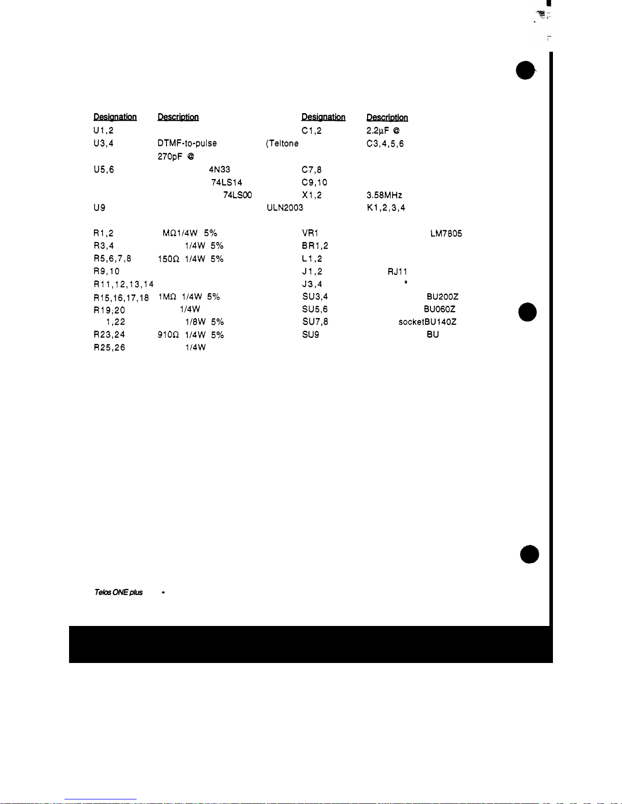
DTMF-to-Rotary Converter
Board
PARTS
LIST
u1,2 DTMF decoder (Teltone M-957) C1,2
u3,4 DTMF-to-pulse converter (Teltone M-969)
270pF 0 1000
U5,6 Optoisolator 4N33 C7,8
u7 hex inverter 74LS14 C9,lO
U8 Quad NAND gate 74LSOO x1,2
u9 Octal open collector driver ULN2003
R1,2 1 MR1/4W
5%
VRl
R3,4 330R 1l4W
5%
BR1.2
R5,6,7,8 150R 1/4W
5%
L1,2
R9,lO 330R 2W
5%
J1,2
R11,12,13,14 75R
2W
5%
J3,4
DPDT relay
R15,16,17,18
1MR 114W
5%
su3,4
R19;20
47R 1/4W
5%
SU5,6
R2 1,22 150R 1l8W
5%
SU7,8
R23,24 910R 1l4W
5%
su9
R25,26 220R 114W
5%
nescm
2.2pF @ 25V
C3,4,5,6
..
not stuffed
not stuffed
3.58MHt crystal
K1,2,3,4
+5V regulator LM7805
bridge rectifier
green
LED
dual
RJ11 jack
6
-
pin 0.1 " connector
20
-
pin socket BU2OOZ
6-pin socket BU060Z
14-pin socketBU140Z
16-pin socket BU 160Z
Telas:
ONEPIUS
ONE
-
DTMF-TO-ROTARY
CONVERTER
BOARD
Page 70

wl
1
lo''
'
I
1
I
d
f
r
+-
r
-1
J
Page 71

Accessory
PCB
Module
BASIC
AUTO-ANSWER
BOARD
Teks
ONE
plus
ONE
-
BASIC
AUTO
ANSWER
BOARD
Page 72
BASIC AUTO-ANSWER BOARD
Purpose
The auto-answer board
is
used
when automatic answering and hang-up of
the Telos One hybrid
is
desired. The circuit
turns
the hybrid on
in
response
to ringing voltage on the
connected phone line, and
turns
the hybrid off
when a break
in
loop current is detected. The loop current interruption, often
referred to
as
CPC,
or Calling Party Control,
is
present on most telephone
lines. However, some central office equipment or
PBXs
may not provide it
and other detection methods will have to be
used
in
that
case.
Installation
The board is installed by plugging
it
into the header connectors on the Telos
One board. Remove
the
small
jumper plugs on
HDRl
first.
The auto-answer board should be removed and the jumpers replaced
if
use
with other than Central Ofice
-
type lines with talk battery is expected,
since the diodes in the loop detect section will cause severe audio
distortion
if
not biased
by
talk battety.
Operation
Not much excitement here. With the board installed, the hybrid will
automatically answer and hang
-
up.
Circuit Description
U1,
R4, and
C2
form
the ring detect section. C2 blocks
DC
so
that only the
AC
ring
voltage will trigger
U1.
When Ul's diode gets current, its transistor
pulls
HR1-2 low
turning
the hybrid on. C3 prevents false tripping.
The remaining components
form
the loop current detector. When loop
current
is
present,
U2's
transistor conducts
and
C1
is
discharged. When loop
current
goes
away, C1
charges
through the diode
in
U3
thus causing a low at
HR1-1 for the length
of
the R3/C1 time constant. Upon restoration of loop
current, the capacitor discharges through
R5 and
D5.
The C1/R5 time
T&s
ONE
PIUS
ONE
-
BASIC
AUTO
ANSWER
BOARD
Page 73
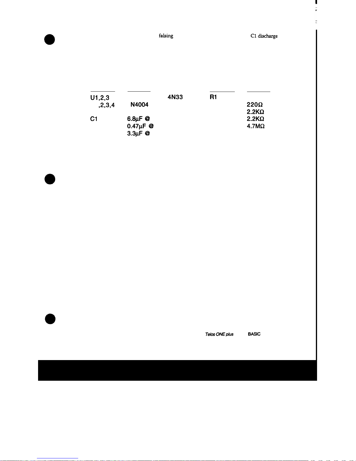
constant prevents faking during
initial
answer by preventing
C1
discharge
on brief
periods
of
loop
current
presence.
Basic
Auto-answer Board
PARTS
LIST
Desianation
Description
Desianation
Description
U1,2,3
opto-isolator
4N33
R1
1
oon
Dl ,2,3,4
1
N4004
dioide
R2
2200
D5
1
N4148
diode
R3
2.2Kn
c1
6.8pF @ 25V R4 2.2KQ
c2 0.47pF @ 200V R5 4.7MO
c3 3.3pF @ 25V
Tebs
ONEplus
ONE
-
BASIC AUTO
ANSWER
BOARD
Page 74

Telos
basic
AutoAns
Rev
3.1
Page 75

Accessory
PCB
Module
"
SUPER" AUTO-ANSWER
BOARD
Telos
ONEplus
ONE
-
SUPER
AUTO
ANSWER
BOARD
Page 76

I
INTRODUCTION
GENERAL
DESCRIPTION
The “Super” Auto-Answer board
is
a plug-in PCB module for the Telos
One which provides reliable auto
-
answer and disconnect
as
well as other
functions:
*Remote control for
sed,
drop
and
auto
functions
Status
indicators for off-hook condition and auto mode
Open collector
outputs
from an integral DTMF decoder
Selectable answer
on
first ring or after
three
rings
Disconnect on drop
or
reversal of talk battery (CPC)
Disconnect on dial tone detection (selectable enable/disable)
Auto mode enabled by remote button or dip switch position
.
Since the unit’s operation is controlled by a microprocessor, the
functionality may
be
changed by reprogramming the EPROM-based processor.
For instance, future versions may be configured with an
I
2
C serial bus
interconnect,
so
that multiple
units
could communicate with a master
controller. The software
-
based control logic permits configuration for
operation on non
-
standard (or non-USA) phone
lines
as
well.
ANSWERING
FUNCTION
The auto-answer board responds to the standard USA ringing signal of
90
VAC
at
20
Hz.
The system
is
protected from the false detection sometimes
caused
by dial-pulses on adjacent
lines,
or other causes, by a software function
which counts AC
cycles
and integrates them over time.
DISCONNECT FUNCTION
Disconnect may result from any of the following:
Loopcurrent interruption
Loopcurrent reversal
Detection of dial tone (selectable)
Loopcurrent interruption
occurs
on most telco lines when the calling party
hangs up. It is sometimes referred to
as
CPC, or
CaZZing
Party
Control,
since
the
CaZZing
party
controls
your
equipment when he hangs up. The CPC
Telos
ONE
plus
ONE
-
SUPER AUTO
ANSWER
BOARD
Page 77

interruption was probably never intentional, having
been
a by-product of
early
mechanically-switched relay-controlled exchanges.
Thus,
some phone
lines
do not provide
this
function or they provide it unreliably. However,
with the proliferation of answering
machines
which rely upon CPC, most
central office equipment now
has
this
capability designed
in.
In
some
cases,
though, it
is
necessary to specifically request
this
feature from the phone
company on a per
-
line basis.
Loop-current reversal, on the other hand,
has
long
been
a phone company
signalling method. First used between the telco's
own
central offices, loop
reversal was later employed to communicate with some large premises PBX
systems.
Thus,
lines
which
are
set up for for PBX
use,
or originate at central
offices with large concentrations of business customers, sometimes
use
this
method. (However, the preferred and more modem situation for PBX control
is
to
use
either "ground-start lines" or
"EM
signalling.
" A digression from
matters relevant here. Both are discussed in the
Telos Telephone
Q&A
-
which you should have, since it comes packed with every Telos hybrid.)
As
mentioned above, while most exchanges do provide CPC, there are
some that don't reliably provide it, or provide it after a variable time
delay
...
and
most PBX's don't generate it. For
this
reason,
this
"
super" auto
-
answer board
has
a "failsafe" dial tone detector. Every
(USA)
telco central
office eventually
returns
dial tone to
its
lines when the calling party
hangs
up.
Thus,
we
use
the presence of dial tone to
cause
a
~~SCOM~C~
when the
loopcurrent detection methods fail.
The auto
-
answer board uses a sophisticated software-implemented
statistical approach to ensure that the line
is
never inappropriately
disconnected.
Four
tones
are
continuously monitored:
350,440,480,
&
620
Hz.
When
the
two tones
(350
&z
440
Hz)
which comprise
dial
tone
are
detected
as
simultaneously present, a onesecond detection "window
"
is
opened. Only
if,
during
this
window, both dial tones are present for more
than
W/O
of the time
and both of the other tones are present for less
than
20%
of the time
is
a valid
dial tone condition decided. In this way, false
"
talk-off" from noise,
applause, or other spectrally
-
rich audio
is
prevented.
Tebs
OrvEplus
0rv"E
-
SUPER
AUTO
ANSWER
BOARD
Page 78

REGARDING DETECTION
OF
DIAL AND DTMF TONES IN
SYSTEMS
WITH
CONFERENCING
CAPABILITY
The
auto-answer board is connected
so
as to receive the hybrids
separated telco
receive
audio signal. Were this not the case, and the
detector was merely connected across the phone line, there would be
a
major
problem when multiple lines are used together in a conference. Why?
Because the tones would be conveyed to each line in use (through the
switching matrix)
from
mety
other line, causing all
of
the detectors to
respond to the tones
from
all
of
the other lines as well as its own!
Fortunately, the
Telos
One's excellent trans-hybrid loss keeps
this
from
happening. Aren't you glad?
Tebs
ONEplus
ONE
-
SUPER
AUTO
ANSWER BOARD
Page 79

INSTAL
LA
TION
Installation consists of removing a jumper plug from a header connector on
the Telos One and plugging
in
the auto-answer
PCB.
The auto-answer board should be removed and the
jumpers
replaced
if
use
with other than Central' Ofice
-
type lines with talk battery is expected,
since the diodes in the
loop
detect section
will
cause severe audio distortion
if
not biased
by
talk battery.
1)
Remove the Telos One front panel by removing
the
two
black screws on
either end of the front panel. Pull the top
case
forward to remove it. Remove
the
two
similar
screws on the back panel. Hold the rear bezel and gently pull
the rear panel and
main
PCB
out of the bottom case.
2)
On
the bottom of the
PCB,
solder a
small
piece of wire from
U14-4
to
HDR1-5. (The header
is
numbered 1,3,5,7 on one side and
2,4,6,8
on the
other.)
This modifcation. need not be done
on
units w'th serial numbers
greater than
08-100-00901 - Reo.
C
or
later
PCBs.
The jumper wire allows
the auto
-
answer board to have access to the hybrid-separated telephone
receive signal.
HDRl
&
HDR2
locations
and
pinout
3)
The auto answer board mounts on
HDRl
and
HDE.
First, remove the
jumper plug which should be installed across
HDR1-7 and HDR1-8. Line up
the
two
headers
with
the
two
PCB
connectors and push down on the board.
Make sure both headers
are
picking up
all
the pins!
Teb
OnrEplus
ON€
-
SUPER
AUTO
ANSWER
BOARD
Page 80
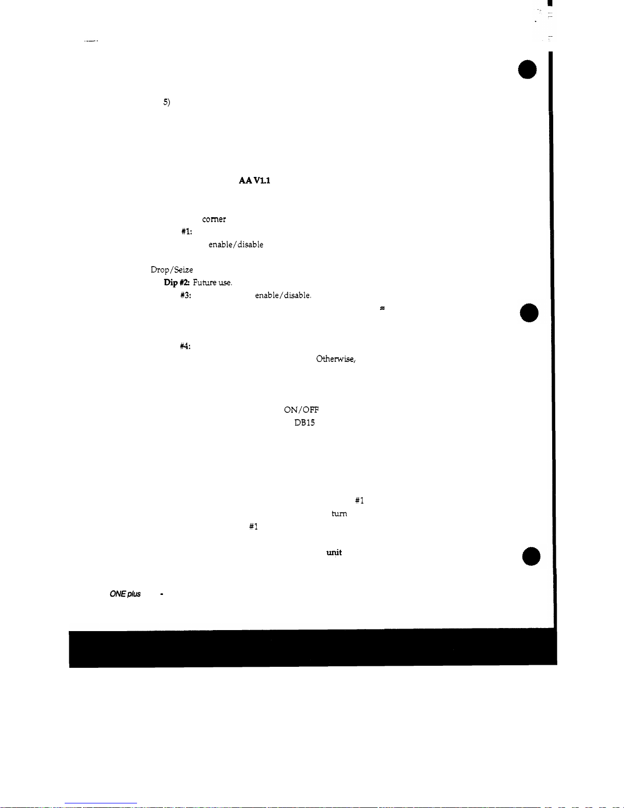
4) Replace rear panel with the new one, mount the DE15 remote
connector,
and
plug the ribbon cable into the
PCB
socket.
5)
Set the auto-answer dip switches for the desired options (described in
the operation section next) before reassembling unit.
OPERATION
SOFTWARE VERSION
AA
VLl
DIP
SWITCH
OPTIONS
Some user-selectable options are provided via a 4-position DIP switch
located in one
comer of the auto-answer PCB.
Functions
are
as
follows:
Dip
#1:
Auto mode permanent enable. Intended for when
no
remote
control of auto
enable/disable
is
available. When on, auto-answer mode
is
always enabled. The remote AUTO input
has
no effect and the remote
Drop/Seize inputs
will
not disable the auto mode.
Dip= Futureuse.
Dip
#3:
Dial tone detect enable/disable. When on and the unit
is
in
auto
mode, will cause a disconnect when
dial
tone
is
present for
=
1
second, or
longer. When
this
switch
is
off, only an interruption or reversal of loop
current will cause a disconnect: dial tone
will
have no effect.
Dip
#4.
The numbersf-rings selector. When on
(and
the system
is
in auto
mode) the unit
will
answer
on
the third
ring.
otherwise, the answer
occurs
on
the first ring.
REMOTE
CONTROL
Remote control of the hybrids
ON/OFF
functions,
as
well
as
the auto
mode, are available on the rear panel
DB15 connector. Remote buttons are
momentary and ground
-
common. (That
is,
they are normally pulled high
through a resistor and taken to ground to activate.) Refer to the connector
pin
-
out table for assignments.
When the
SEIZE
input
is
brought to ground, the auto board
turns
the
hybrid on and disables the auto mode (except
if
DIP #1 is on). When the
DROP input
is
brought to ground the hybrid will
tum
off
and
disable the auto
mode (again, except
if
DIP #1
is
on). The auto mode
is
disabled upon press of
either
of
these buttons
so
that the unit doesn't hang up
from
the dial tone
that would be present on the line when the
et
is
activated
in
order to
Telos
ONEplus
ONE
-
SUPER
AUTO ANSWER
BOARD
Page 81

originate a
call.
The
AUTO
input
also
requires
a momentary pushbutton, but
is
made to
be
alternate action
in
operation.
Each
time the button
is
pressed,
the
auto mode
will toggle to the opposite state. Power
-
up
is
to the "no auto" mode (unless
DIP
#1
is
active).
The
LINE
STATUS
output will be made
low
as
long
as
the hybrid
is
active.
An
external pull-up resistor to the
+5V
pin
is
required to drive an
LED
or similar indicator, since
this
output
is
driven by
an
open collector
device. Should someone press the hybrids front panel
ON
button, the
LINE
STATUS
output will flash a few times before staying on.
This
feature
is
intended to alert anyone watching the remote panel that someone
else
has
activated a unit locally. Neither the front panel
ON
or
OFF
button will
affect the auto mode.
The
AUTO
MODE
status output
is
also
an
open
collector output.
It
is
made
low when the system
is
in the auto mode.
Telas
ONE
@US
m€
-
SUPER
AUTO ANSWER
BOARD
Page 82
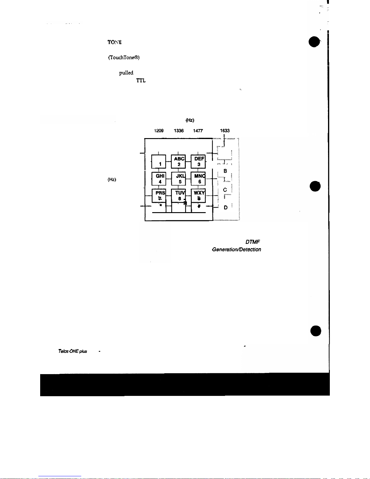
DTMF
TOpiE
DECODER
The auto-answer board brings out to the connector five signals
from
a
DTMF
(TouchToneGD) decoder:
four
DTMF
DATA bits and a DATA VALID
signal. The tones
are
decoded and presented according to the chart.
These
outputs
are
pulled
up
(weakly) on the auto board and thus
may
be
used
as
inputs to standard
TTL
and/or
may
be "wiresred" with other boards for
special
applications.
i
Low
Group
Frequencies
(Hz)
697
no
852
941
High Group
Frequencies
(Hz)
1209 1336 1477 1633
i
3.",.%,.,*
......
+v
..
,..-,....
>
.....
1
:...v
....
i
...............
Ft"jTktj.q/
l-&kjpq{*l.-".
;
..~.~t".i~~.i~i.-.",.-~
,
i*
,,
0
~.,
#
,
$
*-:
.:
A
;
>***e
U.
......
....I
......
....
.........
.:..*
J
I
;
..... ......
..........I
.........
:
........
m
.
....,.
..
.".
c
i
............
..
.....,......
................
OPE
,~
...e.
u.
.-.-
.d
D
...................
Frequencies
and
Buttons for
DNF
Generationrnetection
Tebs
0NEplu.s
ONE - SUPER
AUTO
ANSWER
BOARD
Page 83
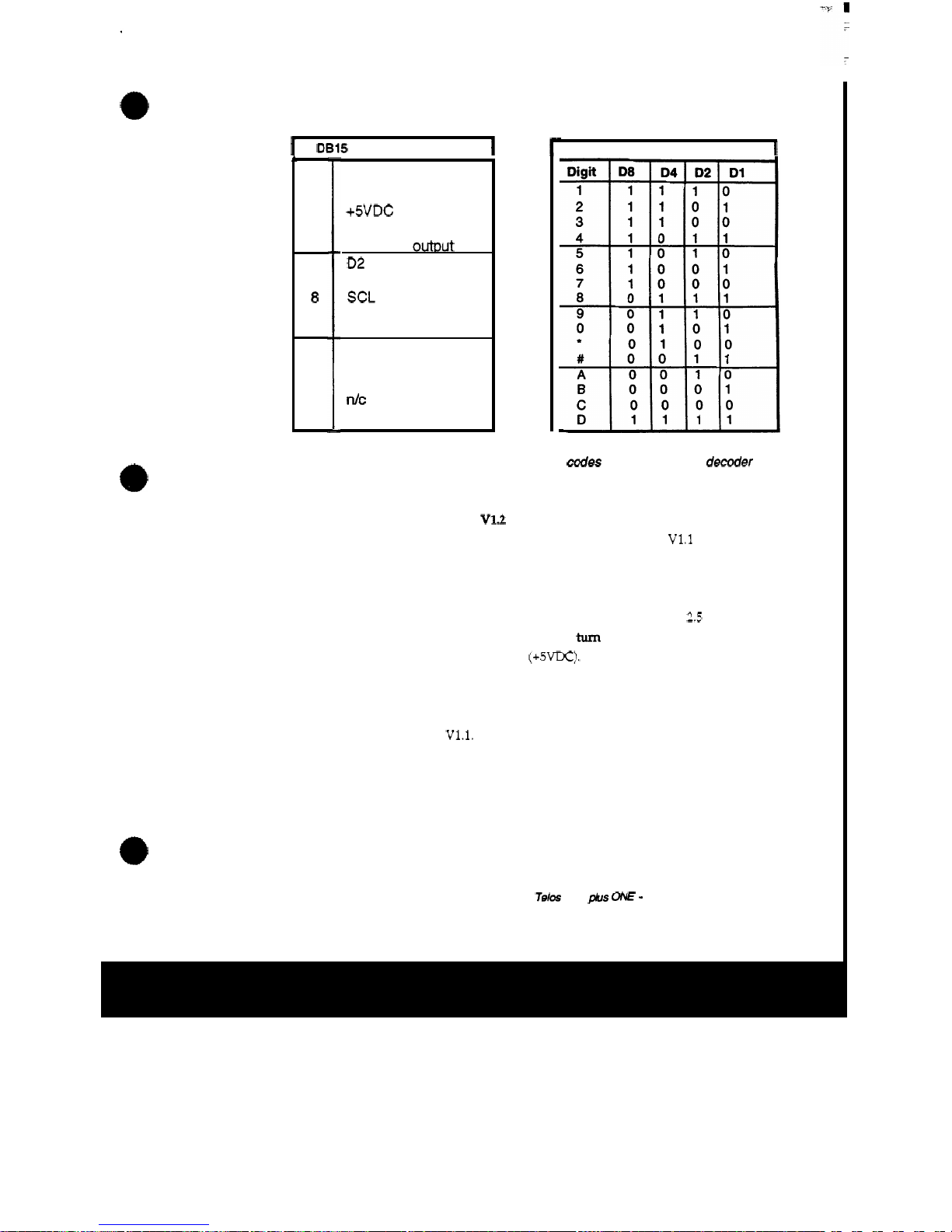
I
DB15 PINOUTS (REMOTE)
1
r
1
2
3
4
5
6
7
8
9
10
11
12
13
14
15
AUTO
control input
DROP
control input
+5VDC
D8 DTMF
output
D4 DTMF
outout
02 DTMF
output
Dl DTMF
output
SCL
SEIZE
control input
Ground
Line
Mode
output
Auto Mode output
DTMF Data
Valid
dC
SDA
Charts showing the hexadecimal codes for the touchtone decoder
and pinouts for the 75-pin remote control connector.
SOFTWARE
VERSION
AA
VU
This version of software functions similarly to
AA
V1.1
with the
following differences:
1)
The SEIZE input no longer disables the
AUTO
function
when pressed.
2)
The SEIZE input can
also
be
used
as
a MAINTAINED input. That is,
if
the SEIZE input pin
is
held
LO
(to ground) for more
than
about
2.5
seconds,
the hybrid will
turn
on (obviously) but will
turn
off
(release the line) when
the SEIZE input returns to a logic
HI
(+5VDC).
3)
The DROP input will not disable the
AUTO
function while the SEIZE
input
is
held
LO,
but will
turn
the hybrid off still.
If
the SEIZE input
is
used
for momentary action, however, the DROP input will disable the auto
functions just like
AA
V1.1.
This means that the operator can still enable and disable the auto
function from a momentary
LO
signal on the
AUTO
pin while the SEIZE input
is
being held
LO.
If
the DROP input
is
brought
LO
while the SEIZE input
is
being held
LO,
the hybrid
will
turn
off but the auto function cannot be toggled
anymore
via
the
AUTO
input. The auto function will remain
in
the state it
DTMF
OUTPUT
CODES
1
Telos
ONE
@US
ONE
-
SUPER
AUTO
ANSWER
BOARD
Page 84
was in when
the
DROP pin went LO.
This
is
done to signal the operator that
the device that initially turned
the
hybrid on via a maintained
closure
has
not released the
SEIZE
input yet. The ON/OFF and
AUTO
outputs will
still
function normally.
All
other
functions
of
AA
V1.1
have been retained.
SOFTWARE
VERSION
AA
V20
This
software version is designed for
use
with multiline
1A2
key system
telephones. It will turn the hybrid on whenever an active line button is
pressed on the key phone and turn the hybrid off when the line button
is
popped up, either by hitting another button half way, pressing an unused
button
(i.e. no phone line connected for that button),
hanging
up
the
handset
or placing a line on hold.
Circuit modifications: The
ring
detector optoisolator,
U3,
should be
moved to the voltage detector circuit,
U4.
R2
should be
33KQ
C5 must be
removed, and the
DTMF
receiver chip,
U7,
should not
be
stuffed.
Call
Telos
if
you'd like the
DTMF
decoder option restored to your unit.
Key phone modification: One key phone must be modified to get
T/R
audio from the selected line to the hybrid. Inside the phone, a
RED
and a
GREEN
wire
go
from
the switch bank to the network under the touchtone pad,
the RED wire to terminal
6,
the GREEN wire to terminal
8.
Remove these
wires from the terminal block and run them to the hybrid's
LINE
modular
jack. Now take another pair of
wires
and
run
them from the hybrids
PHONE
modular jack BACK TO THE
TERMINAL
BLOCK pins
6
&
8.
Essentially,
we're putting
the
hybrid IN SERIES with the phone he that has 'been
selected. That
is,
when the hybrid
is
in its
OFF
mode the phone line
is
looped through the hybrid back to the phone's network.
When
the
hybrid
turns
ON, a relay closes, moving the
T/R
from the phone and into the hybrid.
DIP
SWITCH
OPTIONS
DIP
#l:
When on, enables the
AUTO
function; when
off
the
AUTO
'
function can be toggled on & off
via
the
AUTO
button input provided on the
connector,
J7-1.
DIP
Not supported.
DIP
#3:
Dial
tone detect enable/disable. When on and the unit
is
in auto
mode, will cause a disconnect when dial tone
is
present for
=
1
second, or
longer. Same
as
V1.l.
You
might want
this
option active if your talents tend
to select inactive lines!
DIP
#4:
Was
for number of
rings
selector. Disabled in software, since
this
pin
is
now looking for
DC
voltage to answer, not
cycles
of AC
ring
voltage.
Telos
ONE
plus
ONE
-
SUPER
AUTO
ANSWER
BOARD
Page 85
,
All other remote control functions (remote seize, remote drop, line
status,
auto status, auto on/off) remain the same. It
is
recommended that
the
key
phone handset be
OFF-HOOK
so
the key phone's buttons flash at the correct
rates. If the talent wants to release a line without taking another caller, he
can hit the hook switch to pop the button
up!
If
the phone must be
used
normally, the hybrid must be turned off manually. One way to do
this
is
to
rewire the disconnect button to function
as
the autoanswer board's DROP
signal.
(The disconnect button
is
an optional button on some key phones; it's
used
to disconnect a line without
having
to
pop
the button up.) If your phone
doesn't have the disconnect button already, add a momentary button across
pins
J7-2
&
J7-10
and mount it either on the phone or near the phone.
We
recommend turning on
DIP
#1
and then installing the board
in
your
unit. Of course, you
can
take advantage of the other options by connecting
some extra momentary switches and some
LED
indicators.
This
way the
operators can toggle between
AUTO
and
NO
AUTO,
turn the hybrid on and
off
manually and have indicators
of
the hybrids status
as
well. Refer to
this
manual's
OPERATION
section for a circuit you
can
build up that will do
this.
If
touchtones are needed to dial out and must
be
heard on the air, another
touchtone pad should be fed into the hybrids mix
-
minus scheme. The
touchtone pad in the key phone needs the
-48V
from the phone line to
operate,
so
it would need
its
own power supply. Another scheme could use
some
type
of relay circuit that would reconnect
ONLY
the touchtone pad in
the key phone
(NOT
the network!)
to
the line selected
ONLY
while dialing
.
We don't want the tone pad hanging on
the
line all
the
time, because it will
load down
the
line. Since the tone pad
is
also
powered from the phone line, it
will only
be
active while it
is
connected to the phone line through the relay.
Some stations
use
prerecorded carts
with
tones
on
them,
so,
for instance, the
mayor's
unlisted
home phone doesn't
go
out on the air!
Page 86
"
SUPER" AUTO ANSWEWRELEASE ADDENDUM
#1
SOFIWARE
VERSION
AA
V3.1
This
version of
software
is
very similar to the
AA
V1.1
software, but
is
intended for use on the telephone system
of
France. Here are the major
differences:
1)
Ring
detection
is
based on the French
ringing
frequency
of
%Hz.
2)
Dial tone release has been changed to differentiate between the
various reorder tones applied on the French telephone network. First, the
French phones
use
only
a
MHz
tone (instead of the MHz + 35OHz
used
in
the
US).
More precisely, a steady MHz tone will not
turn
the unit off.
Rather, a
MHz
tone that
is
pulsed at a rate of
1/2
Hz flO%(the French
reorder tone) will
turn
the hybrid
off.
Moreover, a
MHz
tone that
is
on for
1.5
sec.
and off for 3.5
sec.
f1Ph
(another
type
of reorder tone)
will
turn
the
hybrid off,
as
well.
All
DIP
switch options are identical to
AA
V1.1.
as
well
as
all
the
I/O
signals on the 15-pin connector, including remote on/off /auto, their respective
indicator outputs, and the decoded
DTMF.
Telo~
ONE
PIUS
ONE
-
SUPER
AUTO
ANSWER
BOARD
Page 87
.
"
SUPER" AUTO ANSWEWRELEASE ADDENDUM
#2a
(supercedes Addendum
2)
SOFTWARE
VERSION
V5.2
This
version of software
is
intended for use on the Italian telephone
system. The Italian phone
-
system
uses
a non-standard reorder tone
(425Hz)
that
is
pulsed at a rate
of
200
msec.
on/
200
msec.
off.
Ring
frequency
is
50
Hz.
HARDWARE CONSIDERATIONS: In order to recognize this tone the
hardware must
be
changed. First, the crystal frequency
is
changed to make
the call progress detector chip detect
=Hz.
Because of the short duration of
the tone, this chip has
a
difficult time detecting a valid tone.
So,
an
extra
op-amp section
is
added to the hardware to ensure a high enough level
is
presented to the chip's input. To avoid line release from music and other
sources the talk-off portion of the code
has
been modified to detect
four
consecutive tone sequences. Should the levels not
be
consistently high enough,
the unit may take more
than
four beeps to
turn
off. The DTMF decoder will
not operate at all because its reference frequency
has
been changed (to
accommodate the
call
progress detector chip).
SOFIWARE CONSIDERATIONS:
This
version of software can
be
used with
the Telos
DTMF-to-Rotary Dial converter board. When a DTMF tone
is
present on the
send
input of the hybrid,
the
converter board will hold the
hybrid's "on
"
pin low.
This
is
done
so
that the hybrids output
is
muted
during pulse
dialing.
Furthermore, the Super Auto-answer boards software
must not
try
to
tum
the hybrid off because of T/R reversal or loop drop, which
could happen during pulse
dialing.
(See
the schematic of the converter board
for details.)
This
software version addresses this problem by looking at the
"
on" pin while in the "off-hook mode and compensates for the pulse dialing
by adding a time
-
out period after the "~n" pin
has
been released. It then
goes
back to the current detectors to reset
its
"
when-to-tum-off sequence.
AA
V5.2
supports all DIP switch options (identical to
AA
V1.1.)
as
well
as
most all the 1/0 signals
on
the 15-pin connector, including remote
on/off/auto, and their respective indicator outputs. The decoded DTMF
outputs are disabled and should not
be
used.
Page 88
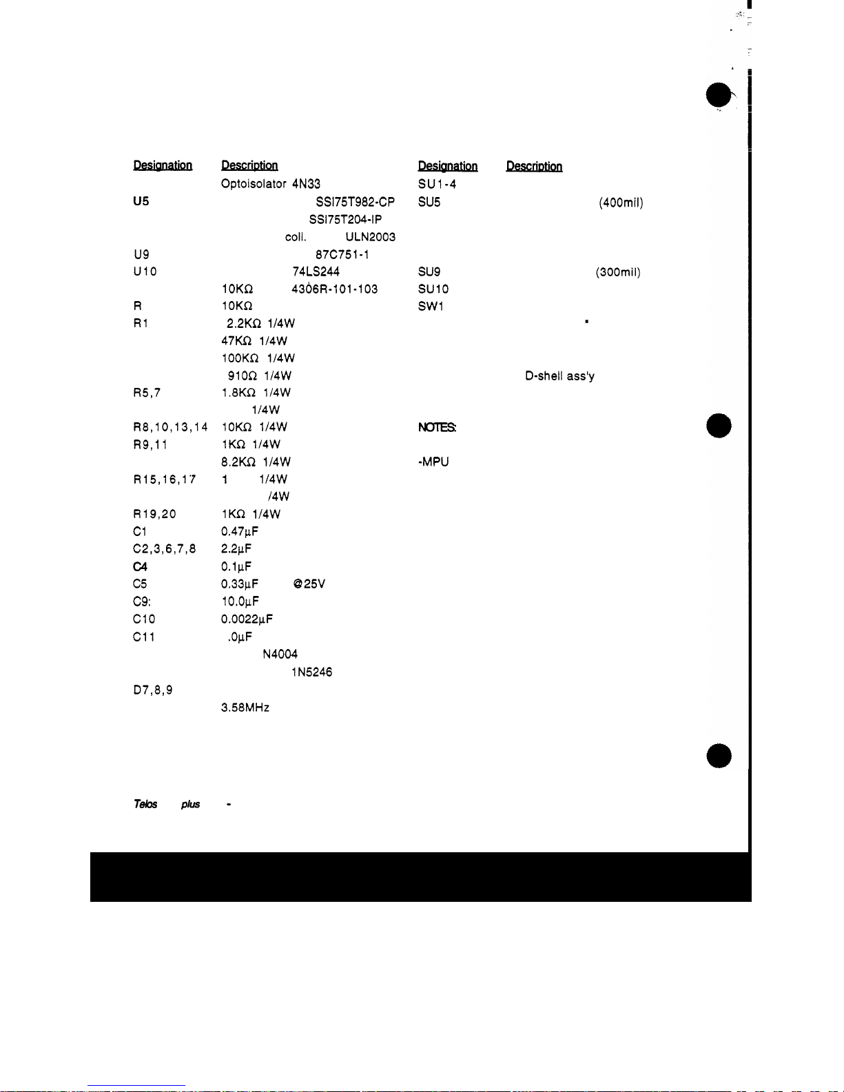
Super Auto-answer Board
PARTS
u1-4
us
u7
U8
u9
UlO
RP 1
R
P2
R1
R2
R3
R4
R5,7
R6
R8,10,13,14
R9,ll
R12
R15,16,17
R18
R19,20
c1
C2,3,6,7,8
c4
c5
c9:
c10
c11
Dl
-
5
D6
D7,8,9
x1
LIST
Optoisolator 4N33
Call Prog Detect SS175T982-CP
DTMF Decoder SS175T204-IP
Octal open coll. driver ULN2003
Microprocessor 87C751-1 N24
Octal buffer
74LS244
10KR SIP 4306R-101-103
lOKR SIP 4310R-101-103
2.2KR 1/4W
5%
47KQ 1l4W
5%
100KR 1/4W
5%
910R 1/4W
5%
1.8KR 1/4W
5%
47R 114W
5%
1OKQ 1/4W
5%
1KR 1/4W
5%
8.2KQ 1/4W
5%
1
OOR
1/4W
5%
1
OMR
1 /4W
5%
1KQ 1/4W
5%
0.47pF mono
2.2pF tant. 9 25V
0.1pF mono
0.33pF tant. 925V
1O.OpF 025V
0.0022pF mono
1
.OpF 025V
diode
1
N4004
Zener diode 1N5246
signal diode 1 N4148
3.58MHz crystal
Descrmtnct
su5 22-pim socket (400mil)
su7 14-pin socket
su9 24-pin socket (300mil)
SU10 20-pin socket
sw1 4-position DIP
SW
..
SU1-4 6-pin socket
SU6 8
-
pin socket
SU8 16
-
pin socket
16
-
PIN
RT
ANGLE HEADER 0.1 " spacing
8
-
PIN FEMALE HEADER 0.1" spacing
4
-
PIN FEMALE HEADER 0.1" spacing
15
-
pin female FRC D-shell ass'y
NOTES
-
All sockets machined pin, selective gold
-MPU must be programmed; available from Telos.
Refer to text for software options.
Tebs
ONE
PIUS
ONE - SUPER AUTO
ANSWER
BOARD
Page 89

c
Page 90

.
Page 91

Page 92

t
Tutorial
ELECTRONIC PHONE
SYSTEMS
Tebs
ONE
plus
ONE
-
ELECTRONIC
PHONE
TUTORIAL
Page 93

Electronic Phone Systems
This
tutorial introduction to electronic phone systems may be
helpful
if
you desire to
COM&
a Telos hybrid to such systems.
The cable from the phone
sets
to the "common equipment" must
convey:
Power to operate the phone
A
two-way data path
The speech audio path
The early electronic phones used a separate pair for each of the
three
functions, and thus required
six
wires. The AT&T Horizon
was an example of
this
approach. Another
is
the popular Merlin
system which
uses
four pairs.
The most common approach
used
in new designs
is
a two pair, four
-
wire scheme.
In
this
scheme, the talk and data are each balanced
and each use one of the
two
pairs. The power is "phantom
"
applied between the two pairs in a way similar to the method
used for phantom powering condenser microphones
in
recording
studios.
+v
to
power
phone
Audio in
~+~~&~~
I
I
Audio
to Set
*
*
Electronic Phone Scheme Using
Two
Pairs - Note fhat this diagram
shows
data
flow
in only one direction for simplicify.
A
transformer
is
generally used at each end of the audio pair
so
that the phantom power
may
be added. The data pair often
uses
resistors to obtain a "center tap" rather than transformers since the
data signal has
DC
components that would not pass through a
transformer.
Telos
ONEplUs ON€ - ELECTRONIC
PHONE
TUTORIAL
Page 94
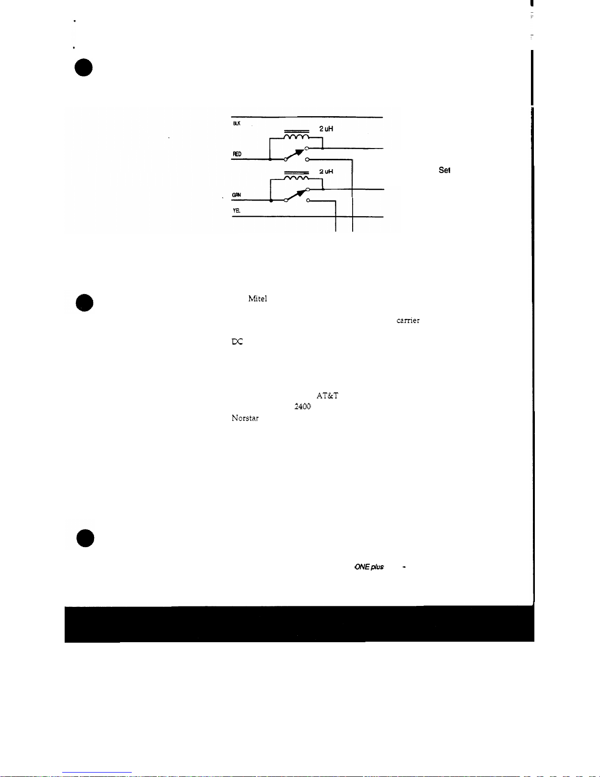
Usually, in the
two
pair approach, the center
two
wires on the
modular plug are the audio path.
To
Phone
Sel
To
Hybrid
One method for interfacing to some electronic phones. The
chokes
pass
the
DC
voltage to the phone set when the
hybrid
is
active.
The Mite1 "Superset" phones
use
a unique scheme that requires
only one pair for all
three
functions. How do they do it? The data
is
amplitude shift modulated onto a
32
kHz
camer "over voice
"
and then the combined voice and data are AC coupled across the
DC
power voltage.
The most advanced systems
use
a pure digital bit stream for both
voice and data. The phone set contains the CODEC for conversion
to and from the analog and digital domains. The pure digital
approach
is
used
in
the AT&T System
85
and the digital version of
the NEC NEAX
2400
as well
as
in the new Northern Telecom
Norstar system.
Since most electronic phone systems use an analog talk path, a
hybrid can be connected to the system by inserting it in the analog
path by breaking the connection from the phone switching
equipment to the instrument. Usually, the
talk
audio
is
found on
the center
two
wires of the line going to the phone. Looping
this
through the hybrid gets the audio connected.
The operator is responsible for turning the hybrid on and off upon
initiation of each call. The hybrid's on and off remote may be
Telos
ONE @us
ON€
-
ELECTRONIC
PHONE
TUTORIAL
Page 95

.
connected to the console's on/off logic outputs to perform
this
,
function.
This
scheme works well for one-call-at-a-time situations
as
you would have in a newsroom or production studio or for
occasional on-air
use.
A
problem
remains,
however, when
calls
need to
be
taken one after
the other, as
in
a
talk show situation.
In
most
cases,
the hybrid
must be signalled each time
a'new'line
is
selected
so
that adaption
to the line can
occur.
It may be possible to derive an appropriate
pulse from the phone by
tacking-on an external circuit of some kind
which would trigger the hybrid's remote on/off function.
Remember too, the hybrid should
be
switched off or its input audio
removed when no line
is
active. Otherwise, the hybrid will
proceed to adjust itself to the high impedance presented to it and
may take a few seconds to recover from
this
condition when a call
is
subsequently taken.
Your
kindly phone supplier may
be
able to
help.
If
you have any luck along these lines, please let
us
know
so
that we can produce an application note for other
users.
With phone systems that have a digital talk path, the situation
with the
on/off control is as above with the additional
complication that you need to
find
a way to get at the converted-
teanalog
signal
inside the phone
set.
Perhaps some poking around
with
a scope or headphones may be
useful in
this
endeavor. Again, maybe your phone provider
company might help. Please let
us
know what you find!
A
universal way to obtain an audio signal from
any
phone
is
to
use
an
adapter which plugs into the handset jack. These should be
available from your local telephone supplier. If you have
problems finding an adapter locally, we may be able to help.
Telos
ONEplus
ONE
-
ELECTRONIC
PHONE
TUTORIAL
 Loading...