

Page 1
TECHNICAL DATA PACKAGE
I
MODEL
CIF612
I
Station
IS0
Electronics
9300-5537-00
Rev
D
2/94
Page 2
TABLE
OF
CONTENTS
SECTION
1.1INTRODUCTION 1-1
1.2DESmON
1.3
POWER
1.4CONNEXTIONS
15SPEClFICATIONS 1-2
LIST
SECTION
2.1MEmCAL 2-1
2.2ELECTRIC AL 2-1
2.2.1GROUM)ING
2.2.2
2.3SIGNALCONNECTIONS
2.3.1 INTEXCOM TO CAMERAS 2-1
2.3.2 CAMERA INTERCOM CHANNEL SELECTION
2.3.3 CONTROL STATIONS 2-1
2.4 SElTING
1:
INTRODUCTION AND SPECIFICATIONS
.....................................................
......................................................
REQUIREMENTS 1-1
...............................................
.....................................................
....................................................
OF
ASSEMBLY DRAWINGS 1-1
2:
INSTALLATION 2-1
.............................................
...............................................
......................................................
........................................................
...................................................
POWER
SUPPLY 2-1
.................................................
................................................
...........................................
..............................................
THE
LEVEL
AND
BALANCE CONTROLS
...............................
................................
................................
1-1
1-1
1-1
2-1
2-1
2-1
2-3
2.4.0INTRODUCTION
2.4.1NONISO 2-3
2.4.2ISO
2.5SEITLNGPRIOm 2-5
SECTION
3.1 SYSTEMOVERVIEW 3-1
3.2 MODEL VCP12B OPERATION 3-1
3.3 MODEL CIF612 OPERATION 3-2
SECTION
4.1 INTRODUCTION 4-1
4.2 WARRANTY INFORMATION 4-1
4.3ROUnNEMAINTENAN CE 4-1
4.4ACCESS 4-1
4.4.2CLEANING 4-1
4.4.3 FUSE REPLACEMENT 4-1
SECTION
3:
3.3.1 CH612 CAMERA INTERFACE CIRCUIT CARDS
3.3.2 SW612 CONTROLIISO SWITCH CIRCUITCARDS
4:
4.3.1 SAFETY CONSIDERATIONS 4-1
5:
......................................................
.........................................................
OPERATION
ROUTINE MAINTENANCE 4-1
.....................................................
..........................................................
.......................................................
DIAGRAMS 5-1
.................................................
...................................................
.................................................
..................................................
.............................................
..............................................
...............................
..............................
........................................
.............................................
...............................................
..........................................
................................................
.................................................
2-3
2-3
3-1
3-2
3-2
Page 3
SECTION
1:
INTRODUCTION AND
SPECIFICATIONS
1.1
INTRODUCTION
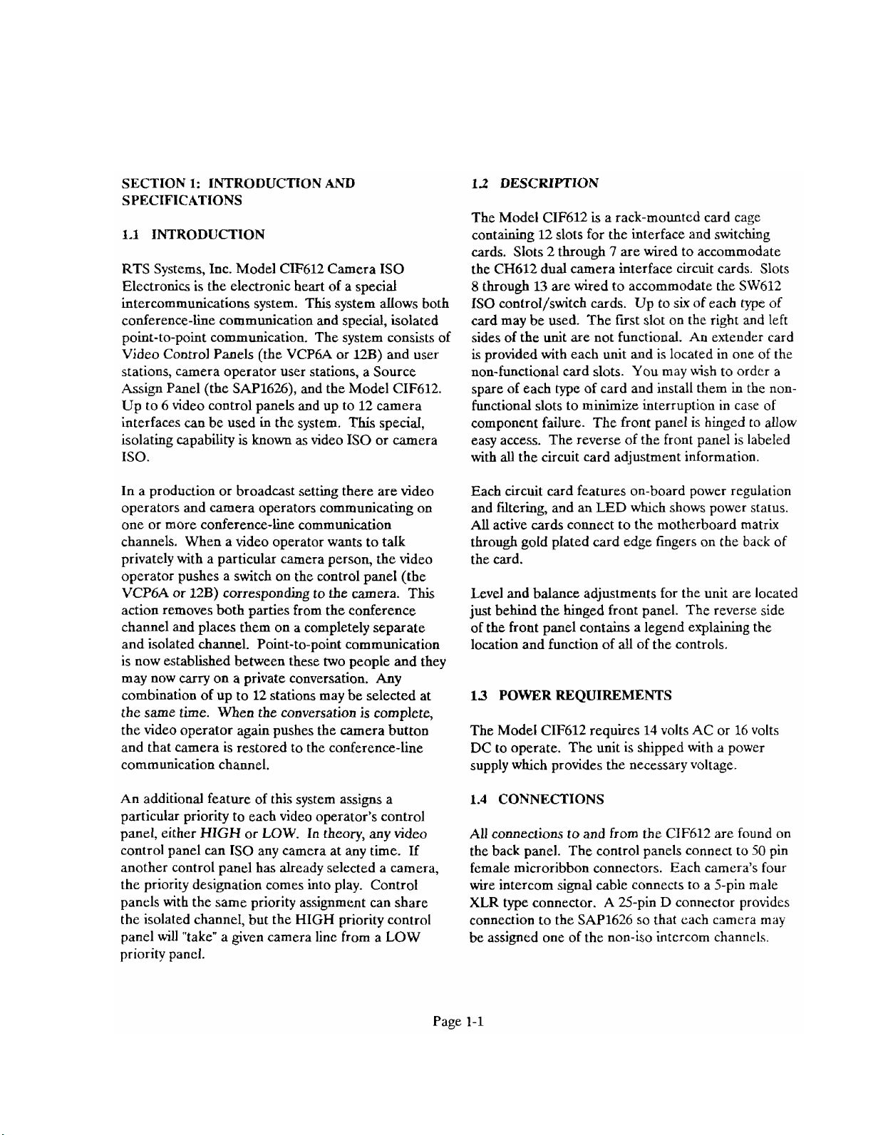
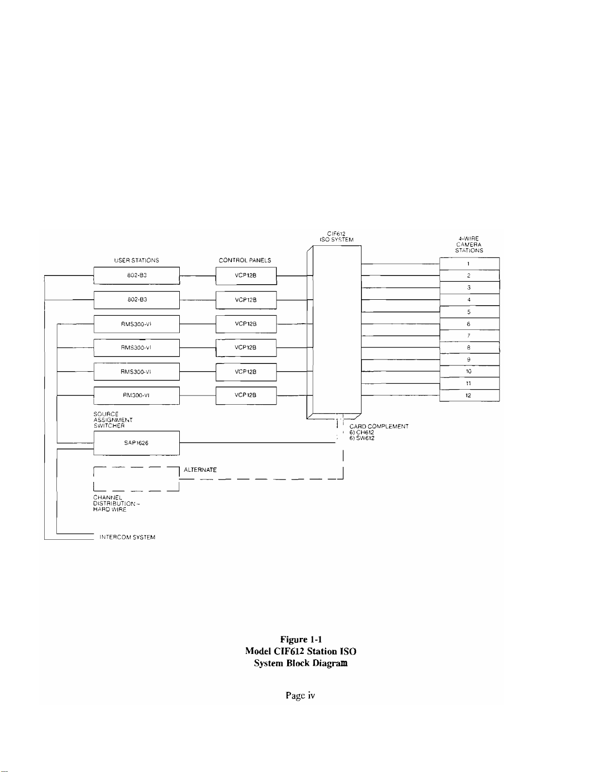
RTS Systems, Inc. Model CIF612 Camera IS0
Electronics is the electronic heart of a special
intercommunications system. This system allows both
conference-line communication and special, isolated
point-to-point communication. The system consists of
Video Control Panels (the VCP6A or
128)
and user
stations, camera operator user stations, a Source
Assign Panel (the SAP1626), and the Model CIF612.
Up to 6 video control panels and up to 12 camera
interfaces can be used in the system. This special,
isolating capability is known as video IS0 or camera
ISO.
12
DESCRIPTION
The Model CIF612 is a rack-mounted card cage
containing 12 slots for the interface and switching
cards. Slots 2 through
7
are wired to accommodate
the CH612 dual camera interface circuit cards. Slots
8
through
13
are wired to accommodate the SW612
IS0 control/switch cards. Up to six of each type of
card may be used. The first slot on the right and left
sides of the unit are not functional. An extender card
is provided with each unit and is located in one of the
non-functional card slots. You may wish to order a
spare of each type of card and install them in the non-
functional slots to minimize interruption in case of
component failure. The front panel is hinged to allow
easy access. The reverse of the front panel is labeled
with all the circuit card adjustment information.
In a production or broadcast setting there are video
operators and camera operators communicating on
one or more conference-line communication
charnels. When a video operator wants to talk
privately with a particular camera person, the video
operator pushes a switch on the control panel (the
VCP6A or 12B) corresponding to the camera. This
action removes both parties from the conference
channel and places them on
a
completely separate
and isolated channel. Point-to-point communication
is now established between these two people and they
may now carry on a private conversation. Any
combination of up to 12 stations may be selected at
the same time. When the conversation is complete,
the video operator again pushes the camera button
and that camera is restored to the conference-line
communication channel.
An additional feature of this system assigns a
particular priority to each video operator's control
panel, either HIGH or LOW. In theory, any video
control panel can
IS0 any camera at any time. If
another control panel has already selected a camera,
the priority designation comes into play. Control
panels with the same priority assignment can share
the isolated channel, but the HIGH priority control
panel will "take" a given camera line from a LOW
priority panel.
Each circuit card features on-board power
regulalion
and filtering, and an LED which shows power status.
All active cards connect to the motherboard matrix
through gold plated card edge fingers on the back of
the card.
Level and balance adjustments for the unit are located
just behind the hinged front panel. The reverse side
of the front panel contains a legend explaining the
location and function of all of the controls.
13
POWER REQUIREMENTS
The Model CIF612 requires 14 volts AC or 16 volts
DC to operate. The unit is shipped with a power
supply which provides the necessary voltage.
1.4
CONNECTIONS
All connections to and from the CIF612 are found on
the back panel. The control panels connect to
50
pin
female microribbon connectors. Each camera's four
wire intercom signal cable connects to a 5-pin male
XLR
type connector. A 25-pin D connector provides
connection to the SAP1626 so that each camera may
be assigned one of the non-iso intercom
channels.
Page 4
1.5 SPECIFICATIONS
CH612 Dual Camera Interface Card
1
Channels
standard RTS
Camera send and receive:
SW612 IS0 Control/Switch Card
through
TW
levels:
12
dBu nominal, balanced, two wire
-10
0 dBu test level
0
dBu
nominal, balanced
-10 dBu nominal, minimum
+
10
dBu
nominal, maximum
Kcy
input 1-12:
Audio to IS0 Station:
Power Requirements:
14 volts AC
16 volt DC
Size
@
@
2 amperes,or
2
amperes
Specification Notes:
closure to ground, 12 volt logic
-10dBu nominal, balanced, two wire
I
OdBu
OdBm
Note: All product information and specifications are subject to change without notice
=
=
-
-
-
-
0.775
Volts r.m.s.
1
milliwatt
0.775
Volts r.m.s. into M)O ohm load
0.387 Volts r.m.s. into 150 ohm load
(0
(-6
dBu)
dBu)
Page 5
SECTION
4:
ROUTINE MAINTENANCE
WARNING
4.1
INTRODUCTION
This section provides service information for routine
maintenance and troubleshooting.
42
WARRANTY INFOFtklATION
The Model CIF612 is warranted for a period of one
year from the purchase date.
A
copy of the warranty
is located at the front of this manual.
43
ROUTINE MAINTENANCE
No routine maintenance is required for the Model
CIF612. To clean, wipe the outer surfaces gently with
a damp cloth.
43.1
Safety Considerations
Although this equipment has been designed in
accordance with international safety standards, this
data package contains information, cautions, and
warnings which must be followed to ensure safe
operation and to maintain the equipment in safe
operating condition. Service and adjustments should
be performed only by qualified service personnel.
Any adjustment, maintenance, and repair of the
opened equipment while any power or voltage is
applied should be avoided as much as possible, and,
when necessary, should be carried out only by a
skilled person who is aware of the hazard involved.
Be certain that only fuses with the required current
rating and of the specified type (normal blow, time
delay, slow-blow, etc.) are used for replacement.
The service information presented in this data
package is normally used with the protective covers
removed and power applied to the equipment.
Energy
available at some points (within the power
supply) may, if contacted, result in personal injury.
4.4
ACCESS
To get inside the Model CIF612, remove the screws
on the sides of the back cover. Carefully tilt the back
cover down.
4.42
Cleaning
Clean the outside of the Model CIF612 with
denatured alcohol or a mild solution of detergent and
water. If required, clean the interior with dry, low
pressure
air.
The circuit boards can be cleaned with
1,1,1 trichloroethane or Freon TF. Do not allow these
or any solvents to get into the pots or switches.
4.43
Fuse Replacement
The Model CIF612 fuses arc found in two locations:
On the individual circuit cards and on the back of the
unit. Replace only with recommended fuse sizes:
CIF612
Frame
2 ampere
slow-blow
Circuit Card
112 ampere
fast-blow
SW612
Circuit Card
112 ampere
fast-blow
Page 6
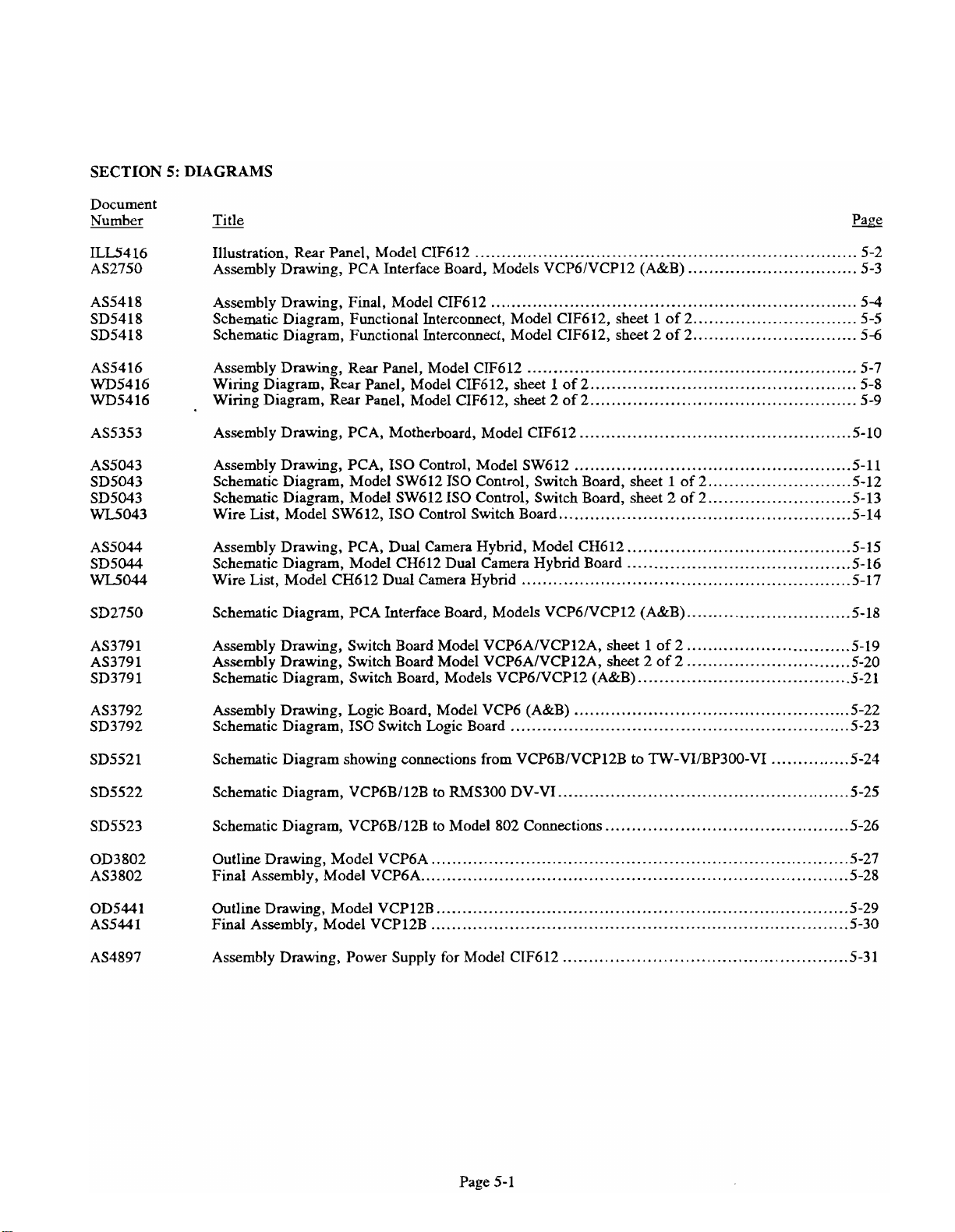
SECTION
Document
5:
DIAGRAMS
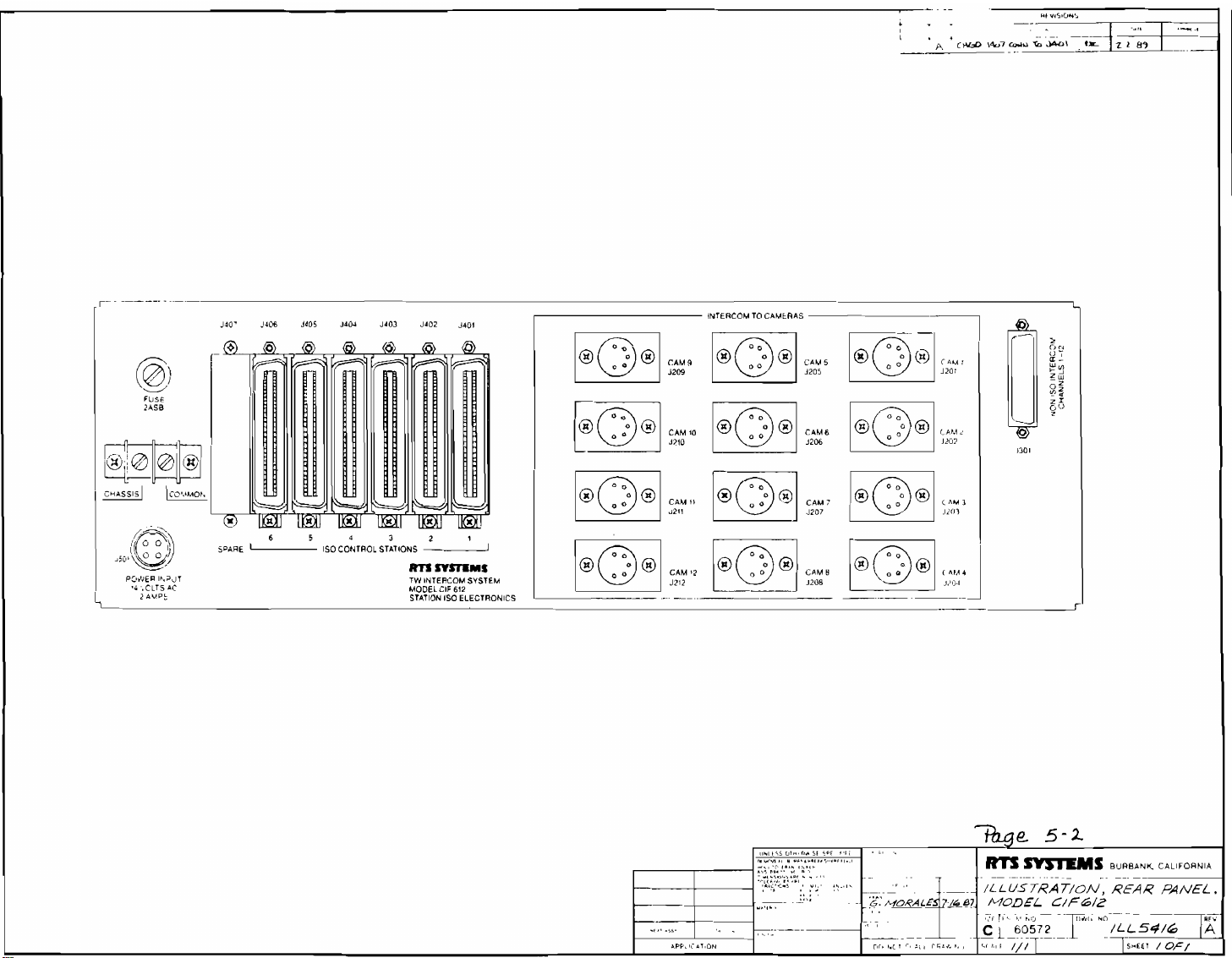
Illustration. Rear Panel. Model CIF612
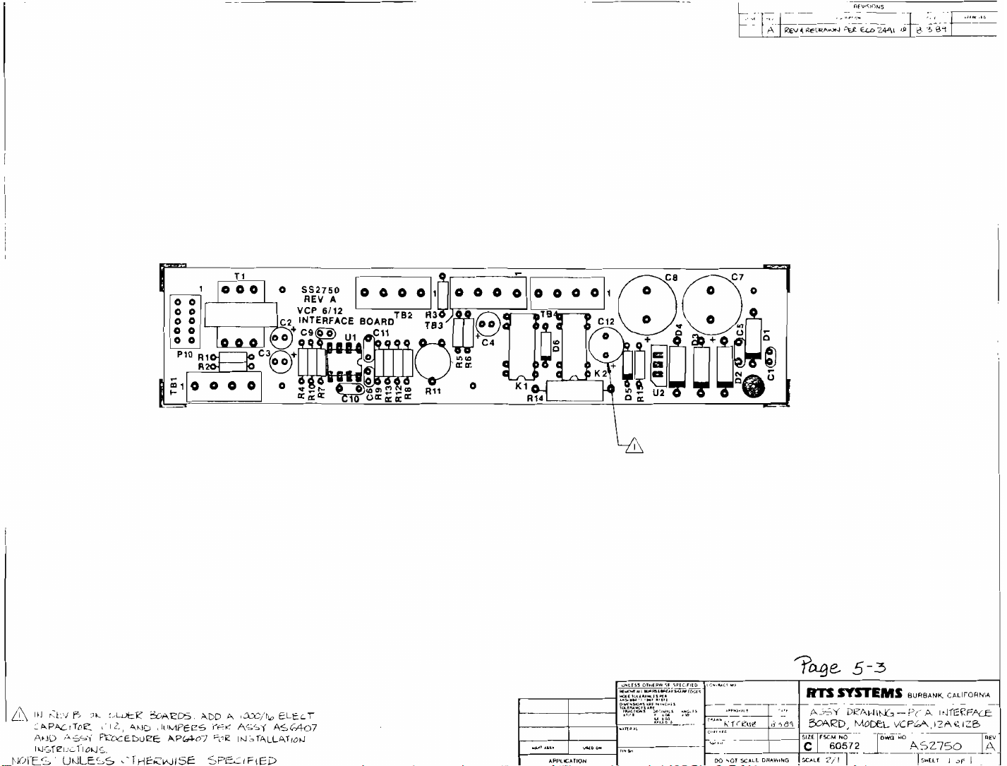
Assembly Drawing. PCA Interface Board. Models VCP6IVCP12 (A&B)
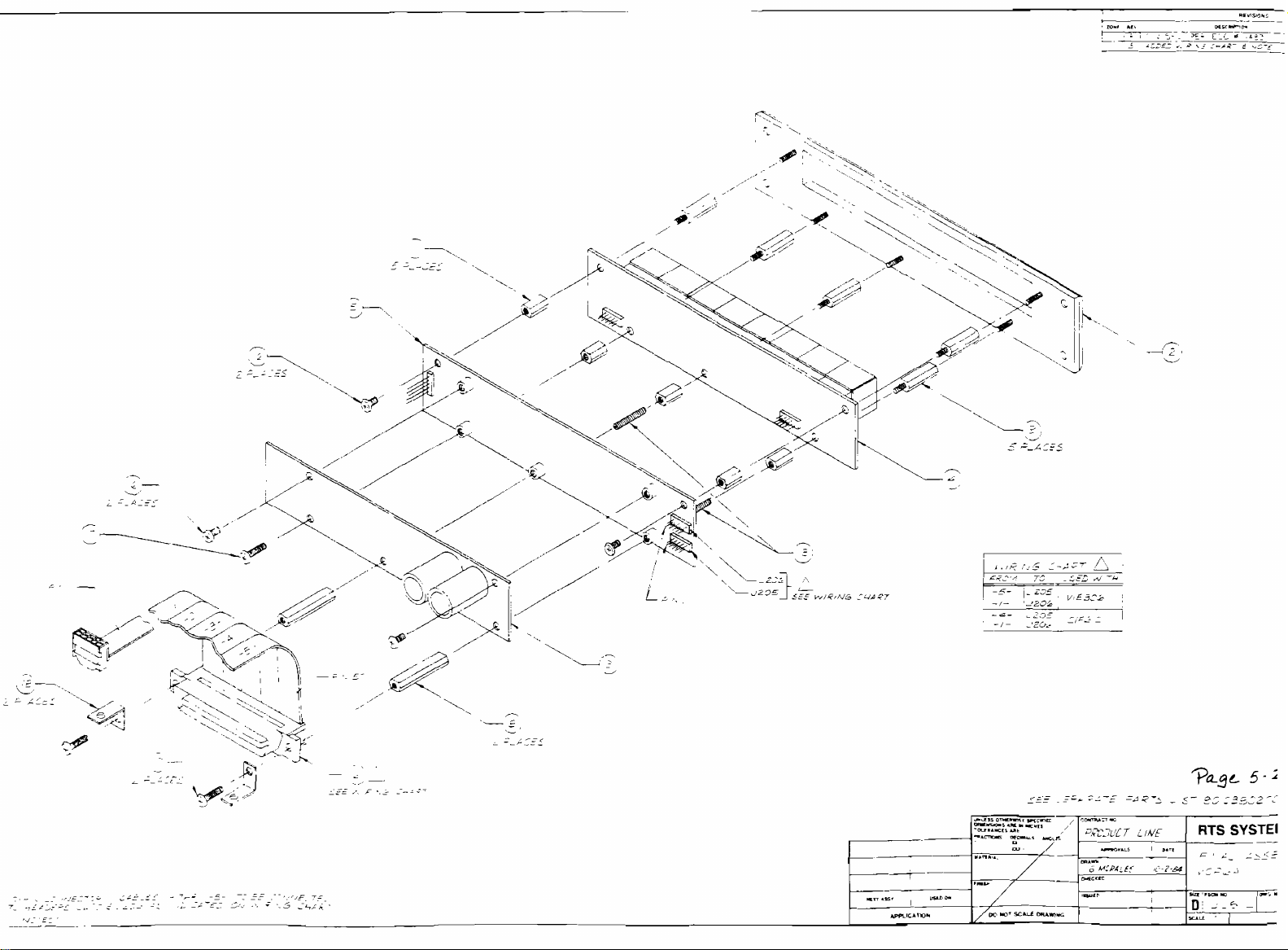
Assembly Drawing. Final. Model CIF612
Schematic Diagram. Functional Interconnect. Model CIF612. sheet
Schematic Diagram. Functional Interconnect. Model CIF612. sheet 2 of 2
Assembly Drawing. Rear Panel. Model CIF612
Wiring Diagram. Rear Panel. Model CIF612. sheet
Wiring Diagram. Rear Panel. Model CIF612. sheet 2 of 2
Assembly Drawing. PCA. Motherboard. Model CIF612
Assembly Drawing. PCA. IS0 Control. Model SW612
Schematic Diagram. Model SW612 IS0 Control. Switch Board. sheet 1 of 2 5-12
Schematic Diagram. Model SW612 IS0 Control. Switch Board. sheet 2 of 2 5-13
Wire List. Model SW612. IS0 Control Switch Board
Assembly Drawing. PCA. Dual Camera Hybrid. Model CH612
Schematic Diagram. Model CH612 Dual Camera Hybrid Board
Wire List. Model CH612 Dual Camera Hybrid
Schematic Diagram. PCA Interface Board. Models VCP6lVCP12 (A&B)
Assembly Drawing. Switch Board Model VCP6AIVCP12A. sheet
Assembly Drawing. Switch Board Model VCP6AIVCP12A. sheet 2 of 2
Schematic Diagram. Switch Board. Models VCP6NCP12 (A&B)
........................................................................
................................
.....................................................................
1
of 2
...............................
...............................
..............................................................
1
of 2
..................................................
..................................................
...................................................
....................................................
...........................
...........................
.......................................................
..........................................
..........................................
..............................................................
...............................
1
of 2
...............................
...............................
........................................
5-2
5-3
5-4
5-5
56
5-7
5-8
5-9
5-10
5-11
5-14
5-15
5-16
5-17
5-18
5.19
5.20
5.21
Assembly Drawing. Logic Board. Model VCP6 (A&B)
Schematic Diagram. IS0 Switch Logic Board
Schematic Diagram showing connections from VCP6BlVCP12B
Schematic Diagram. VCP6B112B to RMS300 DV-VI 5-25
Schematic Diagram. VCP6BI12B to Model 802 Connections
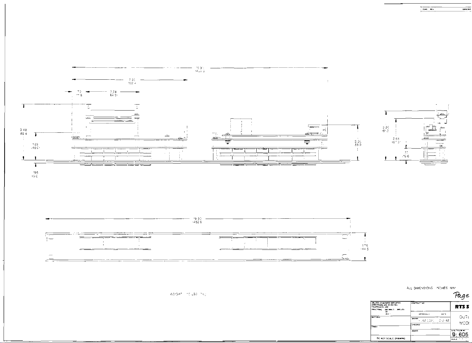
Outline Drawing. Model VCP6A
Final Assembly. Model VCP6A
Outline Drawing. Model VCP12B
Final Assembly. Model VCP12B
Assembly Drawing. Power Supply for Model CIF612
...............................................................................
.................................................................................
..............................................................................
...............................................................................
................................................................
....................................................
to
TW-VIIBP300-VI
...............
.......................................................
..............................................
.....................................................
5.22
5.23
5-24
5.26
5-27
5.28
5.29
5.30
5-31
Page 7
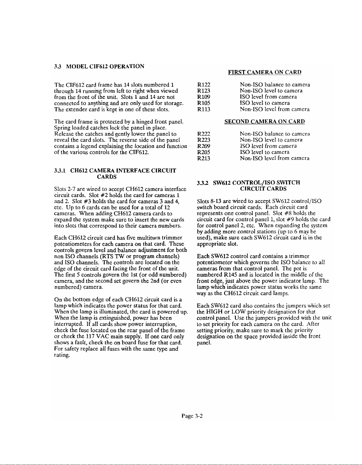
33 MODEL CIF612 OPERATION
FIRST CAblER4
ON
CARD
The CIF612 card frame has 14 slots numbered
1
through 14 running from left to right when viewed
1
from the front of the unit. Slots
and 14 are not
connected to anything and are only used for storage
The extender card is kept in one of these slots.
The card frame is protected by a hinged front panel.
Spring loaded catches lock the panel in place.
Release the catches and gently lower the panel to
reveal the card slots. The reverse side of the panel
contains a legend explaining the location and function
of the various controls for the CIF612.
33.1 CH612 CAMERA INTERFACE CIRCUIT
CARDS
Slots 2-7 are wired to accept CH612 camera interface
circuit cards. Slot #2 holds the card for cameras
and 2. Slot
#3
holds the card for cameras 3 and 4,
1
etc. Up to 6 cards can be used for a total of 12
cameras. When adding CH612 camera cards to
expand the system make sure to insert the new cards
into slots that correspond to their camera numbers.
Each CH612 circuit card has five multiturn trimmer
potentiometers for each camera on that card. These
controls govern level and balance adjustment for both
non IS0 channels (RTS
TW
or program channels)
and IS0 channels. The controls are located on the
edge of the circuit card facing the front of the unit.
The first 5 controls govern the 1st (or odd numbered)
camera, and the second set govern the 2nd (or even
numbered) camera.
On the bottom edge of each
CH612 circuit card is a
lamp which indicates the power status for that card.
When the lamp is illuminated, the card is powered up.
When the lamp is extinguished, power has been
interrupted. If all cards show power interruption,
check the fuse located on the rear panel of the frame
or check the 117 VAC main supply. If one card only
shows a fault, check the on board fuse for that card.
For safety replace all fuses with the same type and
rating.
R122 Non-IS0 balance to camera
Rl23 Non-IS0 level to camera
R109 IS0 level from camera
R105 IS0 level to camera
R113 Non-IS0 level from camera
SECOND CAMERA ON CARD
R222 Non-IS0 balance to camcra
R223 Non-IS0 level to camera
R209 IS0 level from camera
R205 IS0 level to camera
R213 Non-IS0 level from camera
332
SW612 CONTROL/ISO SWITCH
CIRCUIT CARDS
Slots 8-13 are wired to accept SW612 control/ISO
switch board circuit cards. Each circuit card
#8
slot
holds the
#9
holds the card
represents one control panel. Slot
circuit card for control panel
1,
for control panel 2, etc. When expanding the system
by adding more control stations (up to 6 may be
used), make sure each
SW612 circuit card is in the
appropriate slot.
Each SW612 control card contains a trimmer
potentiometer which governs the IS0 balance to all
cameras from that control panel. The pot is
numbered R145 and is located in the middle of the
front edge, just above the power indicator lamp. The
lamp which indicates power status works the same
way as the CH612 circuit card lamps.
Each SW612 card also contains the jumpers which set
the HIGH or LOW priority designation for that
control panel. Use the jumpers provided with the unit
to set priority for each camera on the card. After
setting priority, make sure to mark the priority
designation on the space provided inside the front
panel.
Page 8
USER STATIONS CONTROL PANELS
802-83
aoz-83
-
RMS300-dl
VCP128
(SO SYSTEM
/[---1
CFh12
-
?-WIRE
CAMERA
STATIONS
2
3
4
5
6
-
1
-
RMS300-Vl
-
RhlS300-Y1
-
I
r
i---A
CHANNEL
D~STRBUTIOIC-
HARD'SIIRE
RM300-YI
SOURCE
ASS1G1.IMEI.rT
SYiTCHER
SAP1626
-
-
NTERCOhl SYSTEM
t
-
VCP128
VCP12B
-
-
/-
I
1
CARDCOMPLEMENT
2
61CH612
6)
SW612
8
9
10
11
12
I
-
1
ALTERNATE
-
- -
-
-
- - -
J
-
Figure
Model CIF612 Station
System Block
1-1
Diagram
IS0
Page 9

Figure
hlodel Clf612 Back Panel
3-2
Page 10
FULC
>A58
--
JiO.
Jiob
JPOI
Jlol
J403
J402
dl01
INTLC2COU
TOCAULALS
L
r~
~
i*rrri
PCIIEP
.'
.CLTS1C
>&UP>
7
jio.IMOI.
L?d,
PARE
&i"*i(
SOCONTROLSTATIONS
1
RTI
nmms
IW
INTERCOM
UODELCIFB(2
ITITONIEOELECTRONCS
SISTLM
CAM
1212
iZ
---
-~
..
r
Page 11
~
.
-
~~
.,
~,,
'a
RE",
UeLeruJ
-~
~~
--
~
.
.
.
. . .
,
,M
.
CLD
Z441
~
"
d
~
..
,
...
*..~
?>
--
ill
i
LA
11
r~t,
r:
-
~P~LITo'Z
AbJU
IUST~~~~I'IOU~,
PrjlE5
~c
li5+Y
UdLELS
,'
Ft'cztD~eE
:.L&X
<
~.i
.*Arm
4ki0
HEZw.lSE
.
li~rilPEiiS
APLtl07
ADD
4
,a/li-
('*:<
A<.'>*
IM~T&LL~T~OU
57LtF(ED
ELECT
A5,Woi
pp
.yl..,l
A~*L~A~,~M
""LE,,"..,&m~!.%~r~
-
~-",-~,~,,-",:..,~
ms,-'".,,m.
",."
,
,",
...,~
mw.-.,.~~,,,.~..,
.m,w%~,~"*
,-~,-,
.,,,.
,.~,".,,
,
.-
-'.,,
.-
"
.
*,
',..~
.~"~.,
~
,,.*
-
-
,c.
*',
",
--
...-..,.
--
-
:.,..
KT
-
~,.,..~
.
.
-,,,
--
~
DO
501
YAiL
-
.-
'
d
o*m,*o
A
RTS
YALE
SmEMS
AiY
-RD,
1,)
DXAWilJii-;'(
MOEL
ememr
CALI~ORNIA
p~~-
~-
h
sJTEKFPV
VCP&,IZA<~?B
--
Page 12
ALL
DII.IFYSIOIIS
YlhES
Wkl
%e
Page 13
Page 14
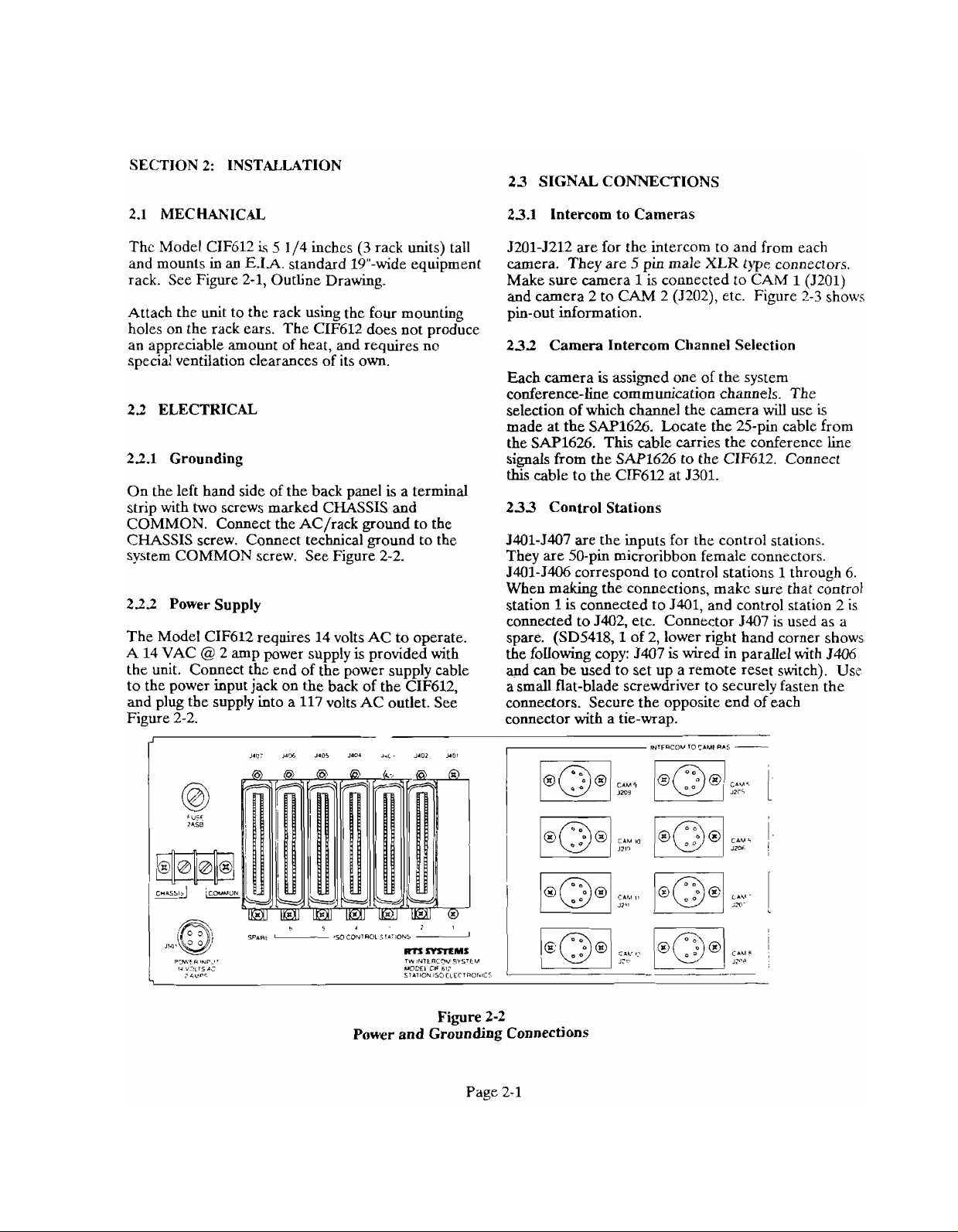
SECTION 2: INSTALLATION
23 SIGNAL CONNECTIONS
23.1 Intercom to Cameras
Thc Model CIF612
and mounts in an
is
5
114 inches
E.IA.
standard 19"-wide equipment
(3
rack units) tall
rack. See Figure 2-1, Outline Drawing.
Attach the unit to the rack using the four mounting
holes on the rack ears. The CIF612 does not produce
an appreciable amount of heat, and requires no
special ventilation clearances of its own.
22 ELECTRICAL
22.1 Grounding
On the left hand side of the back panel is a terminal
strip with two screws marked CHASSIS and
COMMON. Connect the
AC/rack ground to the
CHASSIS screw. Comect technical ground to the
system COMMON screw. See Figure 2-2.
222 Power Supply
The Model CIF612 requires 14 volts AC to operate.
A 14 VAC
@
2 amp power supply is provided with
the unit. Connect the end of the power supply cable
to the power input jack on the back of the CIF612,
and plug the supply into a 117 volts AC outlet. See
Figure 2-2.
1.0
Ym
1.05
i.oa
ic
14112
I'
YO,
5201-3212 are for the intercom to and from each
camera. They are
Make sure camera
and camera 2 to CAM 2 (J202), etc. Figure
5
pin male
1
is connected to
XLR
type connectors.
CAM 1 (3201)
2-3
shows
pin-out information.
232 Camera Intercom Channel Selection
Each camera is assimed one of the system
conference-he co&munieation channels. The
selection of which channel the camera
will
use
is
made at the SAP1626. Locate the 25-pin cable from
the SAP1626. This cable carries the conference line
signals from the SAP1626 to the CIF612. Connect
this
cable to the CIF612 at 5301.
233 Control Stations
J401-5407 are the inputs for the control stations.
They are 50-pin microribbon female connectors.
5401-5406 correspond to control stations
1
through 6.
When making the connections, make sure that control
station
1
is connected to 5401, and control station 2 is
connected to 5402, etc. Connector 5407 is used as a
spare. (SD5418,l of 2, lower right hand corner shows
the following copy: 3407
and
can
be used to set up a remote reset switch). Use
is
wired in parallel with 5406
a small flat-blade screwdriver to securely fasten the
connectors. Secure the opposite end of each
connector with a tie-wrap.
,
INISmCOY
lOr.l"tR"S
-
Figure 2-2
Power and Grounding Connections
Page 15
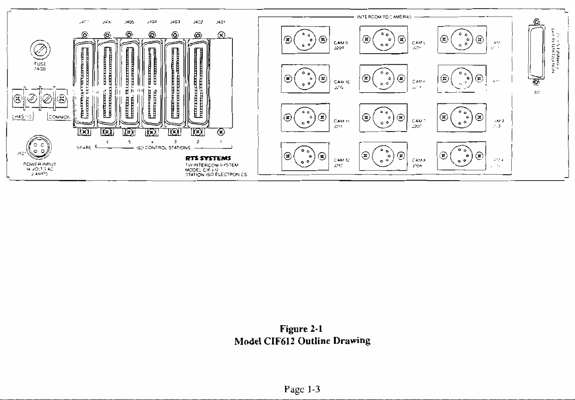
Model
Figure
CIF612
Page
2-1
Outline Drawing
1-3
Page 16

GRN
[PIN
Ti
--=
>+
I
-
-
I>
\,
cxN
BRN
NC
1
BRN
(PIN
3)
v
!
\
I
,
3
SECTION
A
-A
--
~rn
ASS~
-
,)IF(DI~
*
,zb
-
APPLICATION
*--
7
C
USEC
I
UYU
,-
--"a
UI
2
on
lDCU..ill
rUrrPI-
--..a
-
DO
WT
."s
u.
,,,
Yl-
I"
CIU
~
SCALE
!
-
m~llui
I,
SEE
NOTES
-151
"0
-,
v/
iYSTEIV"
my-.
""R.NE/LSON
CL-
UUD
SEPARATE PARTS
:
7??57e
RTS SYSTEMS
-IT
,
9-!O6b
ASSEMBLY
5b'pp;y
81E
F8U
-
ioO572
B
SCUE
1
LIST
m.
9020-4897-00.
6-31
DRAW/nI.5
-
-7
sr
,,/
PXO.
BW.WK,
,
/!=*;z
,
-
m.
AS
]MEET
cww8
-,
--
-.,,:tn
,/
4897
,
CFI
Page 17

Page 18

!
-
C
+
B
-
PIOY
802
J4
2
9
JU@-8
SQUAWK
++,An
REF.
T.27,
31
SD3000
..~~
i
I
788
-
72
!r
j57
'
i
I
1'5
-8
i
I
~
I
!
I
I
P
h
j
-
i
,
4#
A[
I&'
1
TB?
-
-4
I
03
c?~
I
7
I
TB3
12/25
I
-
flu
n
3
_i
I
.
-
1
r
-
"/
?
';'
-
-
CS
-o~/soo
K:
KI
-
VCP
-6
INTERFACE
B3A
RD
A
1
'?a3,
UU--
-.11-01
-I
--
m
m
U
..-
P
wmuoum
~a
4-0.
n-
4
-
-m
-P
OCI
UO
5
J.5
.c.IDu
IfEILSrlN
TEM
5.-
RTS
m."
S(yHEMATlC
57
V(p-6;
-
ma
B
ua3
160572
5-26
SYSTEMS
/TB
RCI~D
I
DIAGRA,
Tc
552
-10
au
XI
a
Page 19

Page 20

5-PIN XL
5-PIN XL
FEMALE
FEMALE
-
GNC I
GNC
2
SS
SS
CHSEL
2
SEL
TO
"/SOM
TO
"/SOM
CONNECTOR
CONNECTOR
CABLE
CABLE
lRr_
5
r
TRI
VCP
-6
INTERFACE
BOA
RG
WHO
9
fagc
u-c.A
-Y.-
-l
LISDIDU
.L-
II
.0-
A
PI
m.
mmuLla*..o
U
-.D
yl
_OILI
-
JYSTEM
IIY
--
,Q
,ij~,'z~~
-
8-,.a,,
RTS
SCHEMATIC
CONNECTIONS
V,cP-62/!LB
B
1
uue
5-24
SYSTEMS
Fuam.
60572
I
uvnsu
DIAGRAM
FRO^
75
Td-/1/255:
mlD
1
SD
10-
SHOI
55.'
11
Page 21

-
-m--
01010111-
-a.1
--
-
0D.KT.D
_
CYrTFM
-,_
?age
I
RTS
5
-
~5
SYSTEMS
a~*r
uwllu.
Page 22

A
INSTALL
FROM ClRCJlT SIDE
INSTALL NON TLI'IEADED SWAGE SPACER !;ITS #1001~01:>001
FROM CiRCJIT SIDE
A
K201 IS NOT INSTALLED INSTALL INSULATED ,&RE JUUPEE~
FROM PIN
3
INSTALL
L!2
0ET:NEEN El S E3 .BROWN WIRE. AND E2
A
INSTALL J203.J205,J206
1 SEE SEPARATE PARTS LIST, PL3792, FOR COMPONENT VALUES
NOTES:
.m.
e-
-.*
6-32x3
7
TO
24
AWG
UNLESS
=~-,
76'
SNAGE STANDOFF RTS $1001-0106-001
2
PLACES
3
PLACES
PIN 14
TWISTED WIRE PNR TO CIRCUIT S13E
ON
ClRCLilT SIDE OF PCB
OTHERWISE
SPECIFIED
8
E4
'TED uVliiEi
3F
PC
,?'~gase
6
....
.&..
..~,...
..,..,
,~..~,~.~
~~<-~
....,~
co ,,OT
SC~~E
~RAWWG
I?TS
1
sraLe
5-22
SYSTEMS
ASSEMBLY,
MODEL
60572
VCP-6Ai6B
jDWG
z-.enux.
cAiFCi.Ni
LOGIC BOARD
"'
AS3792
%we<-
1
OF
8
me
c
Page 23

Page 24

I
.c
I
ZON~REV~
I
I
I
-
SEE
RI%SIONS
DESCRIPnCN
SHEET ONE
MTE
ILPPRoVFD
-
I
I
~~~]~~pgq-Zlpij
I
I
I
L
\
VCP6A
BUTTON LEGEND?
-----
RESET
RESm
-----
I
I
!~~i~~!~~
i
I
i
'L
SWITCHBOARD
-________-----L-_________
9030-3791-02
VCP12A OR VCP12B
BUTTON LEGENR
..
~\~~https://manualmachine.com/l~l~~~
\
I
I
I
I
J
SWiTCHBO.47D
9030-3791-01
I
1
i
I
NOTES: UNLESS OTHERWISE SI'ECIFIED
ASSEMBLY, SWITCHBOARD,
MODEL VCPGA/VCP12A,B
i~c
1
I
Page 25

I
I
4
25
z5
A
sz
2
CLb'i
,
..r
-
r=
,e
u
-
h
-
..3
-
.
'7
.-
3
"
c
d
\
v
I
5
-
72
-
-
-
d
,
,
r
:
1
!
1
35;28
-,.,
.r
5;
CAN
_Cc
5s
>!4
c,
-
-
".,.,
.',C
f
\13
,
i
3/C5
-
3
.5
3i07
i
5
:-
i
.
!
4
L>
-
-.
-
31,s
'2
'4iSCZ
,,,'533?2 ,:v'53338
33/,5.4.
rr
!.4
s:,
-::A.
i
P.
--)
/Z/CI
3
i6-t'
56,
3,
.IR/G~
-
:
m
JW
3.3;,5w
I
I
-
I
C
>
7
e
j
9
.-
,
.
>
-.
,.
-.-#
'7"
.-.ZZA-
,;o
i"
2.3,
-4
.,A'
:.
-;
.A;_'
ti.,
'.
ALL
:
:;E5
\.
l7t'
z
.~C~$E
<e-s=-T
6
,:P
7-
.-
<r.'.T*
~L
.4
"iE
i'ZT
:
..,,
--z*:-=,-,
,
3-
*i
7-:2
:5-..3
~Z,
LYE
75
,:.
'4,
-
A
_
-Ab5
;;r;-i*/.IL;
..,
2
..?<LL
7,.
---
,<~L--z,cE
i/q:~d
<
'4
-I
'.2
:,<:
6
,
I
~W,'C
'*;i;573/:2,.
?isE-,
;,
5,"
-zL3222:
.;LA_
s.<
-z,,B6LzzZ.
<
..~L
?EjiT,
3c;zA'
6
5,,_';rz
::5z-T
Page 26

NC-ES
-lllll....,
,.
,..c
-,-.,
xc,-~
.~~
".
..lr..O
am...-
.%,~..=.,.~,
,..~-
.,.
i-
---:i.
. < ..
-
-
,>.
,.,,
--
..C..'O"_
;:
-
~
!m",~.-.-
~
-*,
:,s-E"
:-
.>
-
?.,-:.
%t
RTS
- - -
ASSElABL'
'P
UODEL
'I
9ge
5-19
SYSTEMS
- - -
,
SITCH
VSP-6A
auEBauK
---
03bfiD
'VCP-1Zb
caL8FoaNir
- - -
Page 27

RDJo~7
,Q/,
2.
iApai/j-aMCE
ALL
REXISTOR5
,.
NDT.55
+.7cj
:
ilrflELs
roc
~4,
jpo
VA
LUEX
ARE
;&
p/c.
5iOdW
CARBON
76
>P
,rx;
ci,
.'
MlC~0.c4RAD5,/
FILM,
mwri
.ii/50
//4
WA77,
+.::
:;
.CL75
i
1%
6
I".rU
O,"iSllY
--LIu.-
-m*"-.-.
--,
-.-.,~
o,.,"-,,"--c"*,
--
-/
".
-YUn->.;.-.
..
,~
'
,-
..
&m
*..--
--"%
..,-
5
*"
-.
AFPL,CAT#O"
I
,
istCI.c"
..,.,
,m
i.--.<-
?...
c.cc*o
,--
.
m
.-"-
woeALss
""I
YALI
!
*"
le
!7 S7
-
I
OWMU9
RlS
SLHEM
qODEL5
SZl
,
C
YALI
?age
S-S
/rw
60572
-
w
D/A6
VCP
5-18
eunmnn
-
IN-7ERFACE
&A
,/.?A<
om
"0
lZB
5D
2
/S*E~
CALIFORNIA
BD
750
/
OF,
Page 28

Page 29

ED
c
2lr7
I0
:z
COM
P,N
-.<
2
4
b
8
ED$€
:REAR
-.
z
n
:
ie
:
ZG
CSi
24
CL*
;a
Z3O
5,J/,ECT5P
vi~w,
I
:
-
'lL
li
5
3
I1
SIC
5
23C
7
ZSC
9
~ic
II
29C
COM
RALAUCED
I
1
"'
I
:
&d3!G
TO
i8C
SJiTI3)J
4C36
I
5
11
L
COM
2
4CbO
/o
iz
COM
COM
COM
344
C52
C
5b
C5€
C
&b
C
(DS
C
70
Z72
r
7~
7
976
$80
31C4
3;c
5
53
C
COM
5,C
I
5953
65C
9
b7C
11
692
COM
71 2 COM
7::
COM
750
rd~
77i
"A,"
19>
CHA:.'!:
,'
DC
Page 30

60 PIN
-
--4
-be
COM ; 6
-
-
-
'OM
hC
N.C.
N.C
N.C. 224
N.C.
KEY
B
COM
COM
COM
COM
COM
COM CAC
COM
COM
COM
COM
COM
CCM
COM
COM
NC C5t
NC
NC
NC Cb4
E36E
(REAR
:2
C
ri
z
,2
:
14
C jb
C
16
ZZC
Zii
3
?L.
228
C3'1
E32
C
34
2
3b
33L
L4Z
244
C4b
C48
C
50
352
5
54
C
Sb
ObO
CDZ
CONNECTOR
VIEW)
,
:
-
fir:
3
2
-
A
5
7 C
F
il
13
/5C
r7
19
Zi
23C N.C.
2SC N.C.
21
?93
31
33: N.C.
35: N.C.
37:
3PC N.C.
41
43;
45
473 U.C.
49:
51
53
'53 COM
573
57:
is,;
03:
CAMERA OUTPUT
2
-
4
CAMERA /,"PUT
CCM
C
-
RiS
C
C
C
L
:
3
;
3
3
C AUDIO TO CAMERA
Z AUD/O
TW
-
B
CAMERA OUTPUT
-
6
C4MERA iNPUT
Cold
NC
N.C.
lit
KEY
A
COM
NC.
N.C.
N.C.
N.C.
N C.
N.C.
TO
N.C.
NC.
N.C.
N.C.
N.C.
AUDIO
FROM
COM
COM
COM
/
DC
VAC
VAC
C"ASSI5
TU
LINE
CAMERA
',At£
A
B
CAMERA A
A
B
Page 31

urr
rn*D
.
"!,?
LI26
DlD,
Viol
no,
Page 32

Page 33

.-%M
WU_JL
XE,
*Pi
7
<TL
u
-
.
<
,
.A
,
-
-i---c-
-~
..
.LL..'"2
-
,
-
;<>
'c<,
>l
-
>
"
.z
iro5
,o*>
.
.
.
~,
.2
i
"'9""-
<
-
,;.
.F,
"
1
4
i
<:
0:s
- -
. .
G.
ri
.c,
:*A
.-
WA-
-
,
~-
..
-
;!
YP_*_
..
~
-
9,
-
-
:i
-
-
-.
:.:
*qm-.
c,-
-
.2
-:
.
-.
-
-.
-2
-
-
-
-
-
Pn,"n,,."-
2..
-
\_
-..
~.
;
_,
-
~*
.:-
-
,..
--
.
-.,
,?
:--.-
..
-
P+,$*,;,
_OW
---
----
\;'
;
,
,
,,
.
-
-a,oe!T"-
lo,.
--!?:
.
-
-
"
",'
-nfloR,T,-
LO*
.
-
>
--
.:%-CC
"R,Y7
.
~
\:
,
:
-:'""?
,,.'
-
,'
.
n:
I:<
*6*
,:
"S*
.-~",.~-
.,G8
qir
-L.,.:-
.
;i-
h9,4
iia,
<
ii.;ii
:urn;.
-
llGr
829
,
,,
"2"
,,9,*
<581D
. .
*<ATE
:onmoi
-
i3c
W,"."-
."
"'
,M,,,
:
-GATE
CO~m"~
Y,YX
-
,
,
. .-
'.
7
CATf
loNmoL4
"2
,x
-
-
z,
2
-
_
",.~/:-?*
3
-
,--
,,<:.
-
,,\
-
'i
<"
+
'ii3'
>
M
-
-
\;;:
-T
=h:
=yo
-czt
"
"
I
+.
2%
=...,-.
'a
,.o,,r,
'i
,,,,,
i",
3'
.:
,
>;-
,"
.,<<
.-
.
,z
"
,,,>
-<
,,7
,3
.,.,A,
A
+,z
,
*+-<
',/'
-.
,~
.2
- -
.-
,5.
a"
<El
'E"
I
au3
a.5
2
nu>
2
8
,
:;
-
A"
9
L;$4>T
-
.,z
LOW
ilSX
-
-<
,.?iz
0,-
--
==-";>I
8
,
(#+
'3'
-
%
a
iL7
+
'Y""
#
izi\:!
-6A-t
CO..,TRO,
//...a::.
.::
$957
<"
-0'
c
S,',,,,"
a,,
,
,7
/'
A-
z5
,
%rV
'
I
8"s
3
I"$
3
;,
8,.
BUS
1
1
XEr
Ail
usi.:,,
8
-
*"
,"
*
UOC"
-
2
.,z
-
?'
)
"i.
POI
5
CONTP02
I
k
-
,:'~
--
\,
-3
,,,
,
-
,.
*SO\
y;
>:'-
-
-~:.:
--3
$:5'-<?3,
-
$'"
"
'
%
PR!on,T,
na
b
zL
%El
dUI
U
.
<
-
~-
i--
&*$"a
-.
-
-
P
),:T[C
RTS
!
10
C9h
-
P*,o#,T"-
'
.o*
.,-
,.'
-
v
,
,.
*-
/,.,
:?:
M
,
:
MC.....
,.,.
"_-.-i...2
lib*
EX3
I-ri".---.
IX
524
...>.-
.
4
c0,,,ilai
."A
jc
_
,
-
,u::7
r5
r:.-c
c,,-
--
-
-
A:
A
A
Page 34

3
-
.
.,
4
I
3
t
2
I
:._I
~,
I
I
I
,~c~".~.
I
FIYIS8ONL
b
3
-
\
NOTE5
..~.
em
2,"
U~TALL€;
-,-
--.
'
-7
1
uiaw,w-
"
-
'Fhge
RTS
L55Y
81"TOT',FRBOAR
s
7.
C
ccrri
....
~
.,.>,
~
.,
.
.~,,~-.,~.,.
.,~
..,...,
..c..
,...,
"c"%,"%..,
~,
..~,.~...
,*.-:";
..
,
,
a,
H,
J'?
72
FXOW
:
FAXS/D€
236
.#,
.~,.
~~-L,:AT#ON
- . -
-
",.
~
..,~
~
"."
. .
.,
~.~".
...~~.
,.,
.
,.
~
...,.
,
.~.".
6.
.~~.c:
L-
,>s.r:
00
.
.~.~,
,.
~
'"0'"-'5
NCT
SCALE
I.3..
60572
,:/
5-10
SYSTEM
ZNG
NC
-
P
'
:<.<
Page 35

Page 36

Page 37

I
7-
,
--~
LC,'
I
123\
:
i
2,-
j-
zfi
2
'
i.
I
I
--
1
?241
j
)/2
jrs
3
!
1
A
..'
3
5ES
2d'
3e,€NTA
A'
i
U6
76LE
-233
BELO,.'
5
LC.
A554i6
T/3.%
513WK
1
rV3EiA/L
SYONS
157
_LOB
FOR
!
5672
_i..2
JNUE(:T3?
A
I3
:YP,L/-
/
I<,,JWNj
3i
ThPJ
THR~E
SET
s3.
Page 38

I
YY..-".-
---.-
.-"
-
-
*-
n
I
I
..-
-
(mylD
--
-..
-
--
?a3=
1-
5
-*
7
-
7
RTS SYSTEMS
L~SEMBLI
PANEL
L/F&/Z
--
iri6
W~W-
-
REAR
CU-NU
Page 39

J,,
-
?
,
<
-
4
-top
j
,
::**vu
.LC
,A(
CUSSII
>I1
.,,
:u,,L
,:tY
.2
-4-
7':
l&-~:-.-C-.-~-I-.-.--;-;---x-/-:-
wo
"b
6
57:
>i5
>-L
;*-,z
:-
;-i+-i-c-3-i-i
>
----
>-:-.-..-
,>O
>#ill
a_i
.
,dJ----:-
.
-
"9
;
.
:
~.
-
a-
---.,-.---.-.:--*-->:-:<4-
-
-2
in%?
.i
.
,
.
<.-~
.x,z
. .
.
,
~-;-;-;d-h&,-,
~.
.-:.-->
.>
cis-i
*-
25
<IIL
.I
. .
.
.
5
:
z
2
.
1
,'
.l
-2
.<
3
5
id:
,
?
;;z
A
1n631
:*q
'd
'i
--..-n
-
-
-.
--
?age
,
.
5
-&
,
:'I
I
RTSSYSTEMS
-
Page 40

Page 41

Page 42

Page 43

Figure
2-3
Connector Locations and Pin-Out Designations
Page 44

2.4
SElTING THE LEVEL
AND
BALANCE
CONTROLS
2.4.0
Introduction
The
LEVEL
and BALANCE controls are preset at
the factory for cameras with 0 dBu nominal send and
receive levels. Once installed only minor adjustments
should be necessary. Each balance control should be
adjusted for minimum
sidetone (or desired level) and
the levels may be set to the operator's preference.
The procedures outlined below are for new cards or
may be performed after changes have been made in
the system set-up.
2.4.1
Non IS0
IS0 level controls are found on cach CH612 Camcra
Interface card.
Adjust one camera at a time. Turn the IS0 level
controls to and from each camera fully clockwise,
20
turns or more. Turn the IS0 balancc control fully
clockwise, 20 turns or more.
Turn the IS0 balance control counter-clockwisise 10
turns.
Now turn the
IS0 level controls
counter-clockwise
13
turns.
Adjust each IS0 level until a comfortable level is
reached.
Each CH612 Camera Interface Card contains two sets
of controls, one set for each camera that the card
interfaces with. Adjust one camera at a time. Make
sure that
all
of the connections to the CIF612 have
been made, and that an intercom signal is traveling to
and from each camera. Turn the non IS0 level
controls to and from each camera fully clockwise, 20
turns or more. Turn the non IS0 balance control
fully clockwise, 20 turns or more.
Turn the non IS0 balance control counter-clockwise
10 turns.
Now turn the non IS0 level controls counter-
13
clockwise
turns.
Make sure an intercom signal is going through the
system to each camera. Adjust each control until a
comfortable level is reached.
Before adjusting the balance, the sidetone within the
camera should be turned off to avoid confusion. Set
the balance to achieve a null in the camera headset.
Only a couple of turns in either direction should be
necessary to reach the null point.
After the balance is
set, reset the camera sidetone. If sidetone is desired,
turn the balance clockwise until a comfortable
sidetone is heard.
Before adjusting the balance, the
sidetone within the
camera should be turned off to avoid confusion .Set
the IS0 balance to achieve a null in the camera
headset. Only a couple of turns in either direction
should be necessary to reach the null point. After the
balance is set, reset the camera sidetone. If sidetone
is desired, turn the IS0 balance clockwise until a
comfortable sidetone is heard.
Repeat this procedure for each camera.
Repeat this procedure for each camera,
The
IS0 balance control for each control panel is
located on the SW612 IS0 Control/Switch Boards, in
the middle front just behind the card handle.
The
Figure
2-4
Balance Control Locations. Model
SWhl2
Page 45

-
GND
Figure
2-5
Level Control Locations, Model
CH612
Page 46

2.5
SEITING
Each SW612
L'p
ICI
!u:l\:. i3111cr.ir
h n
PRIORITY
IS0
Control/Switch board interfaces a control vanel with the cameras connected to the
cJn
he
1h1>
i>
Jdnc
c~~nncrrcd. t~ch cun~rol pancl i> ~~signcd ci1hL.r 3 Ill(iH
on
th~. S\V(rl? Contrul,Sullch Board. The
SW612
b,,arJ muat
,jr
bc
CIF612.
I.O\V
priurit! i.ir
rirnavcd lrclm th~.
card frame to set priority since the priority jumpe; selection is located in the middle of the board. Pull out the
card from the frame, locate the jumper locations, and set the blue jumpers over the appropriate pins. Slide the
card back in. Repeat for each card. As the jumpers are placed over the appropriate pins, carefully mark the
priority assignment for each camera inside the front panel of the frame.
2-6
Figure
Priority Program Jumper Lucations
Page 47

Models
Figure 3-1
VCP6 and VCPlZ Front Panels
Page
2-6
 Loading...