

Page 1

ADDENDUM
BUS EXPANSION CARD
FOR ADAM INTERCOM SYSTEM
9380-7532-000RevC,8/00
™
Page 2

PROPRIETARY NOTICE
CUSTOMER SUPPORT
The RTS product information and design disclosed herein were
originated by and are the property of Telex Communications,
Inc. Telex reserves all patent, proprietary design, manufacturing, reproduction, use and sales rights thereto, and to any article
disclosed therein, except to the extent rights are expressly
granted to others.
COPYRIGHT NOTICE
Copyright 1997 by Telex Communications, Inc. All rights reserved. Reproduction in whole or in part without prior written
permission from Telex is prohibited.
UNPACKING AND INSPECTION
Immediately upon receipt of the equipment, inspect the shipping container and the contents carefully for any discrepancies
or damage. Should there be any, notify the freight company and
the dealer at once.
WARRANTY INFORMATION
RTS products are warrantedbyTelex Communications, Inc. to
be free from defects in materials and workmanship for a period
of three years from the date of sale.
The sole obligation of Telex during the warranty period is to
provide, without charge, parts and labor necessary to remedy
covered defects appearing in products returned prepaid to
Telex. This warranty does not cover any defect, malfunction or
failure caused beyond the control of Telex, including unreasonable or negligent operation, abuse, accident, failure to follow
instructions in the Service Manual or the User Manual, defective or improper associated equipment, attempts at modification
and repair not authorized by Telex, and shipping damage. Products with their serial numbers removed or effaced are not covered by this warranty.
To obtain warranty service, follow the procedures entitled "Procedure For Returns" and "Shipping to Manufacturer for Repair
or Adjustment".
This warranty is the sole and exclusive express warranty given
with respect to RTS products. It is the responsibility of the user
to determine before purchase that this product is suitable for the
user's intended purpose.
ANY AND ALL IMPLIED WARRANTIES, INCLUDING
THE IMPLIED WARRANTY OF MERCHANTABILITY
ARE LIMITED TO THE DURATION OF THIS EXPRESS
LIMITED WARRANTY.
NEITHER TELEX NOR THE DEALER WHO SELLS RTS
PRODUCTS IS LIABLE FOR INCIDENTAL OR CONSEQUENTIAL DAMAGES OF ANY KIND.
Technicalquestionsshouldbedirectedto:
Customer Service Department
RTS/Telex,
12000 Portland Avenue South
Burnsville, MN 55337 U.S.A.
Telephone:(952)884-4051
Fax:(800)323-0498
RETURN SHIPPING INSTRUCTIONS
PROCEDURE FOR RETURNS
If a repair is necessary, contact the dealer where this unit was
purchased.
If repair through the dealer is not possible, obtain a RETURN
AUTHORIZATION from:
Customer Service Department
Telex Communications, Inc.
Telephone:(877)863-4169
Fax: (800) 323-0498
DO NOT RETURN ANY EQUIPMENT DIRECTLY TO
THE FACTORYWITHOUTFIRSTOBTAINING A
RETURN AUTHORIZATION.
Be prepared to provide the company name, address, phone
number, a person to contact regarding the repair, the type and
quantity of equipment, a description of the problem and the serial number(s).
SHIPPING TO MANUFACTURER FOR REPAIR OR
ADJUSTMENT
All shipments of RTS products should be made via United Parcel Service or the best available shipper, prepaid. The equipment should be shipped in the original packing carton; if that is
not available, use any suitable container that is rigid and of adequate size. If a substitute container is used, the equipment
should be wrapped in paper and surrounded with at least four
inches of excelsior or similar shock-absorbing material. All
shipments must be sent to the following address and must include the Return Authorization.
Factory Service Department
Telex Communications, Incorporated
8601 E. Cornhusker Hwy
Lincoln, NE 68505 U.S.A.
Upon completion of any repair the equipment will be returned
via United Parcel Service or specified shipper collect.
2 BUS EXPANSION CARD ADDENDUM
Page 3
INTRODUCTION
This document supplements the ADAM System Installation Guide, document number 9330-7467-000. It describes the usage of Bus Expansion (BX) cards with the
intercom system.
GENERAL DESCRIPTION
Bus Expansion (BX) cards permit interconnection of multiple ADAM frames to increase the size of an intercom
system beyond a single frame. When a single ADAM
frame is used in a stand-alone configuration, it provides
up to 136 intercom ports, with 8 intercom ports being provided by each of the Audio I/O cards in the frame. Standard configurations for a single-frame intercom system
are diagrammed in the ADAM-101 through ADAM-108
Drawings in the ADAM System Installation Guide.
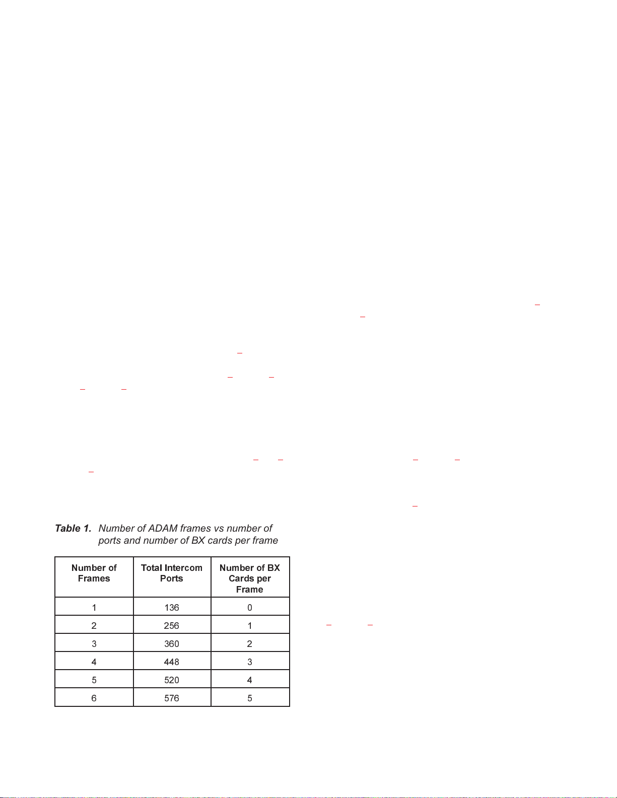
To increase the intercom system size, Bus expansion (BX)
cards are substituted for Audio I/O cards in selected card
slots of each frame. Coax cables interconnect the BX
cards to allow communication between the frames. Each
frame requires a separate BX card to communicate with
each of the other frames in the system. Table
total number of ports provided, and the number of BX
cards required as frames are added. Tables 2 through 6 on
pages 6 through 8 summarize how the card slots are allocated for various sizes of intercom systems.
DIP switches on the BX cards specify the frame number
where each BX card is used and also the total number of
ADAM frames in the expanded intercom system. Settings
for these DIP switches are summarized in Tables
on page 9. Additionally, there is a DIP switch on each BX
card to enable/disable test audio. This feature allows the
BX cards to perform certain self diagnostic functions that
may help the system to recover if the communication path
1 shows the
7 and 8
is temporarily lost. The setting of this switch is described
in the installation notes which follow.
In multi-frame systems, it is necessary to define one
frame as the master frame (frame #1) and all other frames
as slave frames. This is accomplished by DIP switch S1-7
on each Master Controller card. This DIP switch should
be set to "on" for both Master Controller cards in the master frame. It should be set to the "off" position for all other
Master Controller cards in all other frames.
The Master Controller cards also require different firmware, dependent on how many frames are being interconnected, and whether a card is intended for use in the
master frame or a slave frame. To distinguish between
cards with different firmware, a 3-digit suffix number is
stamped on the card after the assembly part number (for
example, Master Controller cards for the master frame in
a 3-frame system will be stamped with assembly part
number 9030-7514, and the suffix number will be -300) .
The various suffix numbers are indicated in Tables
2
through 6.
Each ADAM frame requires its own Master Controller
Breakout Panel. The Master Controller Breakout Panel for
frame #1 has a special function. It provides the connections for the configuration computer and any program assign panels or UIO-256 frames that are used by the
intercom system. The Master Controller Breakout Panels
for the remaining frames are then connected back to the
primary Master Breakout Panel for Frame #1. Connections between the primary Master Controller Breakout
Panel and the other Master Controller Breakout Panels are
summarized in Table
9 on page 9.
For proper operation, the BX cards must be interconnected in a specific pattern. Card interconnections are
summarized on page 5.
Table 1. Number of ADAM frames vs number of
ports and number of BX cards per frame
Number of
Frames
1 136 0
2 256 1
3 360 2
4 448 3
5 520 4
6 576 5
Total Intercom
Ports
Number of BX
Cards per
Frame
The general method of connecting Station Breakout Panels to all ADAM frames in an expanded system is the
same as for a single-frame system. Typical connections of
Station Breakout Panels are diagrammed in the ADAM101 through ADAM-108 drawings in the ADAM System
Installation Guide. However, note that the addition of BX
cards causes some of the port numbers to shift to new
slots. The port numbering information contained in Tables
2 through 6 in this addendum can be used to label the Sta-
tion Breakout Panels in an expanded intercom system.
Once all components of the expanded intercom system are
properly connected, operation is identical to a singleframe intercom system.
BUS EXPANSION CARD ADDENDUM 3
Page 4

INSTALLATION NOTES
When installing Bus Expansion cards to create multiframe ADAM Intercom systems, refer to the following
notes as a supplement to the ADAM System Installation
Guide.
DIP switch S6-4 on each BX card is a test audio dis-
●
able switch:
On (closed) disables test audio
Off (open) enables test audio
Notes to Paragraph 2 of the ADAM System Installation Guide: Mounting the Central Matrix Components
Label the ADAM Card Frames as “Frame 1”, “Frame 2”,
etc. The numbering of the frames is completely arbitrary.
However, the configuration computer must be connected
to the Master Controller Breakout panel for whichever
frame you designate as frame 1. If your intercom system
uses a Trunking Master Controller, or Program Assign
Panels, or UIO-256 Frames, these must also be connected
to the Master Controller Breakout Panel for frame 1.
Therefore, you should number the ADAM Card Frame
which is closest to these devices as “Frame 1”.
Notes to Paragraph 3 of the ADAM System Installation Guide: ADAM Circuit Cards
All Cards
Install all cards in the proper slots using the slot usage table that is appropriate for your intercom system (Tables
through 6 on pages 6 through 8). Be sure to read the following notes for each card type before installation.
Master Controller Cards, Suffix Numbers
Check the suffix number on each Master Controller card
to make sure it is being installed in the correct frame. The
suffix numbers are summarized in Tables 2 through 6 of
this Addendum.
2
The test audio provides enhanced error correction for
communication between the ADAM frames. When
interconnecting more than two frames, always leave
DIP switch S6-4 in the “Off” position on all BX
cards. In a two-frame system, you can also set S6-4 to
the “Off” position; however, you will not be able to
use ports 125 through 128 of frame #1 and ports 253
through 256 on frame #2, since these ports must be
used for the test audio.
DIP switch S6-8 on the BX cards is not used, and the
●
position does not matter.
Notes to Paragraph 9 of the ADAM System Installation Guide: Connections to the ADAM Card
Frame
Connections to Audio I/O Cards and Master Controller Cards
Connections to the AIO and MC cards for all frames are
as shown in the ADAM-101 through ADAM-108 Drawings in the System Installation Guide. The only differences are that the slot numbers and port numbers for the
Audio I/O cards will vary. (Use the slot numbers and port
number shown in Tables
place of the slot and port numbers shown in the ADAM101 through ADAM-108 drawings.)
Master Controller Breakout Panel Interconnections
2 through 6 of this Addendum in
Master Controller Cards, Master vs Slave Frame
Selection (S1-7)
In Frame #1, set DIP switch S1-7 on both Master Controller cards to the “on” position. For all other Master Controller cards in the remaining frames, make sure that DIP
switch S1-7 is set to “off” (factory default setting).
BX Card DIP Switches (S6)
As you install each BX card, make sure that the S6 DIP
switches are properly set:
Set the frame number using Table 7, page 9.
●
Set the total number of ADAM frames using Table 8,
●
page 9. (All of the BX cards will have these switches
set the same.)
4 BUS EXPANSION CARD ADDENDUM
A connection is required from the Master Controller
Breakout Panel of frame #1 to each of the other Master
Controller Breakout Panels. Refer to Table 9, page 9. Use
single-pair data cables for the connections (same type as
is used to connect a PAP-950-50 as shown in the ADAM809 Drawing in the System Installation Guide).
Configuration PC, Trunking Master Controller,
UIO-256, PAP's
These devices should only be connected to ADAM frame
#1. Connections are as shown in the ADAM-101 through
ADAM-108 drawings in the System Installation Guide.
Page 5

Bus Expansion Card Interconnections
Interconnections for a 6-Frame System
The Bus Expansion cards must be interconnected using
coaxial cables. Use the following information when making the interconnections. Note that when interconnecting
Bus Expansion cards, the “TX” jack (top jack) of the first
card connects to the “RX” jack (bottom jack) of the second card and vice-versa.
Interconnections for a 2-Frame System
Frame 1, slot 9 connects to Frame 2, slot 9
Interconnections for a 3-Frame System
Frame 1, slot 9 connects to Frame 2, slot 9
Frame 1, slot 8 connects to Frame 3, slot 9
Frame 2, slot 8 connects to Frame 3, slot 8
Interconnections for a 4-Frame System
Frame 1, slot 9 connects to Frame 2, slot 9
Frame 1, slot 8 connects to Frame 3, slot 9
Frame 1, slot 10 connects to Frame 4, slot 9
Frame 2, slot 10 connects to Frame 3, slot 8
Frame 1, slot 9 connects to Frame 2, slot 9
Frame 1, slot 8 connects to Frame 3, slot 9
Frame 1, slot 10 connects to Frame 4, slot 9
Frame 1, slot 7 connects to Frame 5, slot 9
Frame 1, slot 11 connects to Frame 6, slot 9
Frame 2, slot 10 connects to Frame 3, slot 8
Frame 2, slot 8 connects to Frame 4, slot 10
Frame 2, slot 11 connects to Frame 5, slot 8
Frame 2, slot 7 connects to Frame 6, slot 10
Frame 3, slot 10 connects to Frame 4, slot 8
Frame 3, slot 7 connects to Frame 5, slot 10
Frame 3, slot 11 connects to Frame 6, slot 8
Frame 4, slot 11 connects to Frame 5, slot 7
Frame 4, slot 7 connects to Frame 6, slot 11
Frame 5, slot 11 connects to Frame 6, slot 7
Frame 2, slot 8 connects to Frame 4, slot 10
Frame 3, slot 10 connects to Frame 4, slot 8
Interconnections for a 5-Frame System
Frame 1, slot 9 connects to Frame 2, slot 9
Frame 1, slot 8 connects to Frame 3, slot 9
Frame 1, slot 10 connects to Frame 4, slot 9
Frame 1, slot 7 connects to Frame 5, slot 9
Frame 2, slot 10 connects to Frame 3, slot 8
Frame 2, slot 8 connects to Frame 4, slot 10
Frame 2, slot 11 connects to Frame 5, slot 8
Frame 3, slot 10 connects to Frame 4, slot 8
Frame 3, slot 7 connects to Frame 5, slot 10
Frame 4, slot 11 connects to Frame 5, slot 7
Note
This completes the additional procedures required when
using Bus Expansion Cards. Intercom port connections
for the additional ADAM frames are identical to what is
described in the ADAM System Installation Guide. No
operating procedures are affected.
BUS EXPANSION CARD ADDENDUM 5
Page 6

Table 2. Allocation of card slots for an intercom system with two ADAM frames. "BX" = Bus Expansion Card; "MC" = Master Controller Card (check for
6 BUS EXPANSION CARD ADDENDUM
Slots 1234567891011121314151617181920
Frame #1 1-8 9-16 17-24 25-32 33-40 41-48 49-56 57-64
assembly part number 9030-7514 followed by the proper suffix number -200 as listed in this table); "1-8", "9-16" etc. = port numbers for Audio
I/O Cards
BX
CARD
65-72 73-80 81-88 89-96 97-104
105-112113-120121-128NOT
USED
MC
CARD
-200
CARD
MC
-200
Frame #2
129-136137-144145-152153-160161-168169-176177-184185-192BX
CARD
193-200201-208209-216217-224225-232233-240241-248249-256NOT
USED
MC
CARD
-200
MC
CARD
-200
Table 3. Allocation of card slots for an intercom system with three ADAM frames. "BX" = Bus Expansion Card; "MC" = Master Controller Card (check for
assembly part number 9030-7514 followed by the proper suffix number [-300 or -350] as listed in this table); ports "1-8" , "9-16" etc. = Audio I/O
Cards
Slots 1234567891011121314151617181920
Frame #1 1-8 9-16 17-24 25-32 33-40 41-48 49-56
Frame #2 121-128 129-136 137-144 145-152 153-160 161-168 169-176
BX
CARDBXCARD
BX
CARDBXCARD
57-64 65-72 73-80 81-88 89-96 97-104 105-112 113-120
177-184 185-192 193-200 201-208 209-216 217-224 225-232 233-240
NOT
USED
NOT
USED
MC
CARD
-300
MC
CARD
-350
MC
CARD
-300
MC
CARD
-350
Frame #3 241-248 249-256 257-264 265-272 273-280 281-288 289-296
BX
CARDBXCARD
297-304 305-312 313-320 321-328 329-336 337-344 345-352 353-360
NOT
USED
MC
CARD
-350
MC
CARD
-350
Page 7

Table 4. Allocation of card slots for an intercom system with four ADAM frames. "BX" = Bus Expansion Card; "MC" = Master Controller Card (check for
assembly part number 9030-7514 followed by the proper suffix number [-400 or -450] as listed in this table); ports "1-8", "9-16" etc. = Audio I/O
Cards
Slots 1234567891011121314151617181920
Frame #1 1-8 9-16 17-24 25-32 33-40 41-48 49-56
BX
CARDBXCARDBXCARD
57-64 65-72 73-80 81-88 89-96 97-104 105-112
NOT
USED
MC
CARD
-400
MC
CARD
-400
Frame #2 113-120 121-128 129-136 137-144 145-152 153-160 161-168
Frame #3 225-232 233-240 241-248 249-256 257-264 265-272 273-280
Frame #4 337-344 345-352 353-360 361-368 369-376 377-384 385-392
BX
CARDBXCARDBXCARD
BX
CARDBXCARDBXCARD
BX
CARDBXCARDBXCARD
169-176 177-184 185-192 193-200 201-208 209-216 217-224
281-288 289-296 297-304 305-312 313-320 321-328 329-336
393-400 401-408 409-416 417-424 425-432 433-440 441-448
NOT
USED
NOT
USED
NOT
USED
MC
CARD
-450
MC
CARD
-450
MC
CARD
-450
MC
CARD
-450
MC
CARD
-450
MC
CARD
-450
Table 5. Allocation of card slots for an intercom system with five ADAM frames. "BX" = Bus Expansion Card; "MC" = Master Controller Card (check for
assembly part number 9030-7514 followed by the proper suffix number [-500 or -550] as listed in this table); ports "1-8", "9-16" etc. = Audio I/O
Cards
BUS EXPANSION CARD ADDENDUM 7
Slots 1234567891011121314151617181920
Frame #1 1-8 9-16 17-24 25-32 33-40 41-48
Frame #2 105-112 113-120 121-128 129-136 137-144 145-152 153-160
Frame #3 209-216 217-224 225-232 233-240 241-248 249-256
BX
CARDBXCARDBXCARDBXCARD
BX
CARDBXCARDBXCARDBXCARD
49-56 57-64 65-72 73-80 81-88 89-96 97-104
BX
CARDBXCARDBXCARDBXCARD
257-264 265-272 273-280 281-288 289-296 297-304 305-312
161-168 169-176 177-184 185-192 193-200 201-208
NOT
USED
NOT
USED
NOT
USED
MC
CARD
-500
MC
CARD
-550
MC
CARD
-550
MC
CARD
-500
MC
CARD
-550
MC
CARD
-550
Frame #4 313-320 321-328 329-336 337-344 345-352 353-360 361-368
Frame #5 417-424 425-432 433-440 441-448 449-456 457-464
BX
CARDBXCARDBXCARDBXCARD
BX
CARDBXCARDBXCARDBXCARD
465-472 473-480 481-488 489-496 497-504 505-512 513-520
369-376 377-384 385-392 393-400 401-408 409-416
NOT
USED
NOT
USED
MC
CARD
-550
MC
CARD
-550
MC
CARD
-550
MC
CARD
-550
Page 8

8 BUS EXPANSION CARD ADDENDUM
Table 6. Allocation of card slots for an intercom system with six ADAM frames. "BX" = Bus Expansion Card; "MC" = Master Controller Card (check for as-
Slots 1234567891011121314151617181920
Frame #1 1-8 9-16 17-24 25-32 33-40 41-48
sembly part number 9030-7514 followed by the proper suffix number [-600 or -650] as listed in this table); ports "1-8", "9-16" etc. = Audio I/O Cards
BX
CARDBXCARDBXCARDBXCARDBXCARD
49-56 57-64 65-72 73-80 81-88 89-96
NOT
USED
MC
CARD
-600
MC
CARD
-600
Frame #2 97-104 105-112 113-120 121-128 129-136 137-144
Frame #3 193-200 201-208 209-216 217-224 225-232 233-240
Frame #4 289-296 297-304 305-312 313-320 321-328 329-336
Frame #5 385-392 393-400 401-408 409-416 417-424 425-432
Frame #6 481-488 489-496 497-504 505-512 513-520 521-528
BX
CARDBXCARDBXCARDBXCARDBXCARD
BX
CARDBXCARDBXCARDBXCARDBXCARD
BX
CARDBXCARDBXCARDBXCARDBXCARD
BX
CARDBXCARDBXCARDBXCARDBXCARD
BX
CARDBXCARDBXCARDBXCARDBXCARD
145-152 153-160 161-168 169-176 177-184 185-192
241-248 249-256 257-264 265-272 273-280 281-288
337-344 345-352 353-360 361-368 369-376 377-384
433-440 441-448 449-456 457-464 465-472 473-480
529-536 537-544 545-552 553-560 561-568 569-576
NOT
USED
NOT
USED
NOT
USED
NOT
USED
NOT
USED
MC
CARD
-650
MC
CARD
-650
MC
CARD
-650
MC
CARD
-650
MC
CARD
-650
MC
CARD
-650
MC
CARD
-650
MC
CARD
-650
MC
CARD
-650
MC
CARD
-650
Page 9

Table 7. Bus Expansion Card DIP switch S6 settings to select the frame
number in which the card is used
Frame # DIP Switch Settings: 0=off (open); 1=on (closed)
S6-1 S6-2 S6-3
1000
2100
3010
4110
5001
6101
Table 8. Bus Expansion Card DIP switch S6 settings to select the total number
of ADAM frames and to enable/disable test audio
Number of
ADAM
Frames
2 1** 1 0 0
30010
40110
50001
60101
* 0=enabled; 1=disabled
** In a 2-frame system, test audio may be enabled by setting S6-4 to 0, but this will take
over ports 125-128 of frame #1 and ports 253-256 of frame #2. These ports cannot then
be used for intercommunication.
DIP Switch Settings: 0=off (open); 1=on (closed)
S6-4*
(Test Audio)
S6-5 S6-6 S6-7
Table 9. Master Controller Breakout Panel interconnections
Connect from.. ... to
Frame #1, J8 Frame #2, J8
Frame #1, J7 Frame #3, J8
Frame #1, J6 Frame #4, J8
Frame #1, J5 Frame #5, J8
Frame #1, J4 Frame #6, J8
BUS EXPANSION CARD ADDENDUM 9
 Loading...