

Page 1

Universal Beltpack
Technical Manual
BP-4000 & BP-5000
F.01U.321.601
Rev. 02
November/2017
Page 2
2 Universal Beltpack
Proprietary Notice
The product information and design disclosed herein were
originated by and are the property of Bosch Security Systems,
Inc. Bosch reserves all patent, proprietary design,
manufacturing, reproduction, use and sales rights thereto, and
to any article disclosed therein, except to the extent rights are
expressly granted to others.
Copyright Notice
Copyright 2017 by Bosch Security Systems, Inc. All rights reserved.
Reproduction, in whole or in part, without prior written permission
from Bosch is prohibited.
*All other trademarks are property of their respective owners.
Warranty and Service Information
For warranty and service information, refer to the appropriate web
site below:
RTS Intercoms .............................. www.rtsintercoms.com/warranty
RTS Digital
RTS TW
AudioCom
RadioCom
Intercom Headsets
THE
LIGHTNING
FLASH AND
ARROWHEAD
WITHIN THE
TRIANGLE IS
A WARNING
SIGN
ALERTING
YOU OF
“DANGEROUS
VOLTAGE”
INSIDE THE
PRODUCT.
CAUTION: TO
REDUCE THE RISK
OF ELECTRIC
SHOCK, DO NOT
REMOVE COVER.
NO USERSERVICEABLE
PARTS INSIDE.
REFER SERVICING
TO QUALIFIED
SERVICE
PERSONNEL.
THE
EXCLAM
ATION
POINT
WITHIN
THE
TRIANGL
E IS A
WARNING
SIGN
ALERTIN
G YOU OF
IMPORTA
NT
INSTRUCT
IONS
ACCOMPA
NYING
Customer Support
Technical questions should be directed to:
THE
PRODUCT.
SEE MARKING ON BOTTOM/BACK OF PRODUCT.
Customer Service Department
Bosch Security Systems, Inc.
www.rtsintercoms.com
Technical Questions
Bosch Security Systems Technical Support
WARNING: APPARATUS SHALL NOT BE
EXPOSED TO DRIPPING OR SPLASHING AND NO
OBJECTS FILLED WITH LIQUIDS, SUCH AS
VASES, SHALL BE PLACED ON THE APPARATUS.
http://www.rtsintercoms.com/contact_main.php
Disclaimer
WARNING: THE MAIN POWER PLUG MUST
REMAIN READILY OPERABLE.
The manufacturer of the equipment described herein makes
no expressed or implied warranty with respect to anything
contained in this manual and shall not be held liable for any
implied warranties of fitness for a particular application or for
any indirect, special, or consequential damages. The
CAUTION: TO REDUCE THE RISK OF ELECTRIC
SHOCK, GROUNDING OF THE CENTER PIN OF
THIS PLUG MUST BE MAINTAINED.
information contained herein is subject to change without
prior notice and shall not be construed as an expressed or
implied commitment on the part of the manufacturer.
WARNING: TO REDUCE THE RISK OF FIRE OR
ELECTRIC SHOCK, DO NOT EXPOSE THIS
APPARATUS TO RAIN OR MOISTURE.
WARNING: TO PREVENT INJURY, THIS
APPARATUS MUST BE SECURELY ATTACHED TO
THE FLOOR/WALL/RACK IN ACCORDANCE
WITH THE INSTALLATION INSTRUCTIONS.
Page 3

Universal Beltpack 3
Important Safety Instructions
1. Read these instructions.
2. Keep these instructions.
3. Heed all warnings.
4. Follow all instructions.
5. Do not use this apparatus near water.
6. Clean only with dry cloth.
7. Do not block any ventilation openings. Install in accordance with the
manufacturer’s instructions.
8. Do not install near any heat sources such as radiators, heat registers, stoves,
or other apparatus (including amplifiers) that produce heat.
9. Do not defeat the safety purpose of the polarized or grounding-type plug. A
polarized plug has two blades with one wider than the other. A grounding
type plug has two blades and a third grounding prong. The wide blade or the
third prong are provided for your safety. If the provided plug does not fit
into your outlet, consult an electrician for replacement of the obsolete outlet.
10. Protect the power cord from being walked on or pinched particularly at
plugs, convenience receptacles, and the point where they exit from the
apparatus.
11. Only use attachments/accessories specified by the manufacturer.
12. Use only with the cart, stand, tripod, bracket, or table specified by the
manufacturer, or sold with the apparatus. When a cart is used, use caution
when moving the cart/apparatus combination to avoid injury from tip-over.
13. Unplug this apparatus during lightning storms or when unused for long
periods of time.
14. Refer all servicing to qualified service personnel. Servicing is required
when the apparatus has been damaged in any way, such as power-supply
cord or plug is damaged, liquid has been spilled or objects have fallen into
the apparatus, the apparatus has been exposed to rain or moisture, does not
operate normally, or has been dropped.
Page 4

4 Universal Beltpack
Page 5

Table
of
Contents
Important Safety Instructions ...............................................................................................................3
INTRODUCTION ........................................................................................................................ 7
Features .................................................................................................................................................. 7
Reference View ........................................................................................................................................ 8
External Connections and Controls ........................................................................................................ 9
Connector Description .......................................................................................................................... 10
XLR (3-Pin) ........................................................................................................................................10
XLR (4-Pin) ........................................................................................................................................10
XLR (5-Pin) ........................................................................................................................................10
Specifications ........................................................................................................................................ 11
System Configuration and Power ......................................................................................................... 13
System Configuration .........................................................................................................................13
Power ..................................................................................................................................................13
Channel Power ...............................................................................................................................................13
Local Power ....................................................................................................................................................16
INITIAL SETUP AND CONFIGURATION ............................................................................ 17
Initial BP-4000/5000 Setup ................................................................................................................... 17
UBP (Universal Beltpack) Initialization Troubleshooting Table ....................................................... 18
Setup Mode Indication .......................................................................................................................19
Mode-Sensing Setup .......................................................................................................................................19
Firmware Version ...............................................................................................................................19
Programming the Beltpack ................................................................................................................... 20
Enter Program Menu ..........................................................................................................................20
Exit Program Menu ............................................................................................................................20
Menu System ......................................................................................................................................... 21
Mode Menu ........................................................................................................................................22
Talk Mode Menu ................................................................................................................................23
Mic Gain Menu ..................................................................................................................................24
Page 6

6 Universal Beltpack
Sidetone Adjust Menu ........................................................................................................................ 24
Incoming Call Beep Menu ................................................................................................................. 25
Channel Lock Menu (RTS Mode Only) ............................................................................................ 25
Power Source Menu (RTS Mode Only) ............................................................................................. 26
Mic Kill Menu (RTS and Audiocom Mode Only) ............................................................................. 26
Send Mic Kill Menu (RTS and Audiocom Mode Only) .................................................................... 27
LEDs Menu ........................................................................................................................................ 27
Factory Reset ...................................................................................................................................... 28
OPERATION AND MAINTENANCE ..................................................................................... 29
Operation ...............................................................................................................................................29
Adjust the Volume ............................................................................................................................. 29
Change the Channel (BP-5000) ......................................................................................................... 29
Maintenance ...........................................................................................................................................30
Replace the Beltclip ........................................................................................................................... 30
Set Local Power ................................................................................................................................. 31
Page 7

CHAPTER 1
Introduction
The Universal Beltpacks are portable user stations compatible with RTS, Audiocom, and Clear-Com
party line systems. They are available in 1-channel and 2-channel versions. Both have the mode-sensing
system configuration, meaning the beltpacks can determine what type of system they are installed into
and configure themselves according to that system.
The BP-4000 and BP-5000 can be ordered with either a 4-pin male, 4-pin female or 5-pin female XLR
connector, providing a wide range of headset options. Dynamic and electret headset microphones are
supported.
Multiple programming options are available. To simplify programming, voice prompts guide the user
through menus.
Beltpacks are available in black only.
Features
• Voice prompts for simplified configuration
• Remote Mic Kill turns off all active microphones, reducing background noise
• Programmable TALK button, (Always) On, (Always) Off, Switched, or Momentary
• Mode-sensing System Configuration
• Updated design for modern, sleek appearance
• Reduced current draw allows for more beltpacks being powered by the power supply
• Auto-sensing headset inputs, electret or dynamic
Page 8
8 Introduction Universal Beltpack
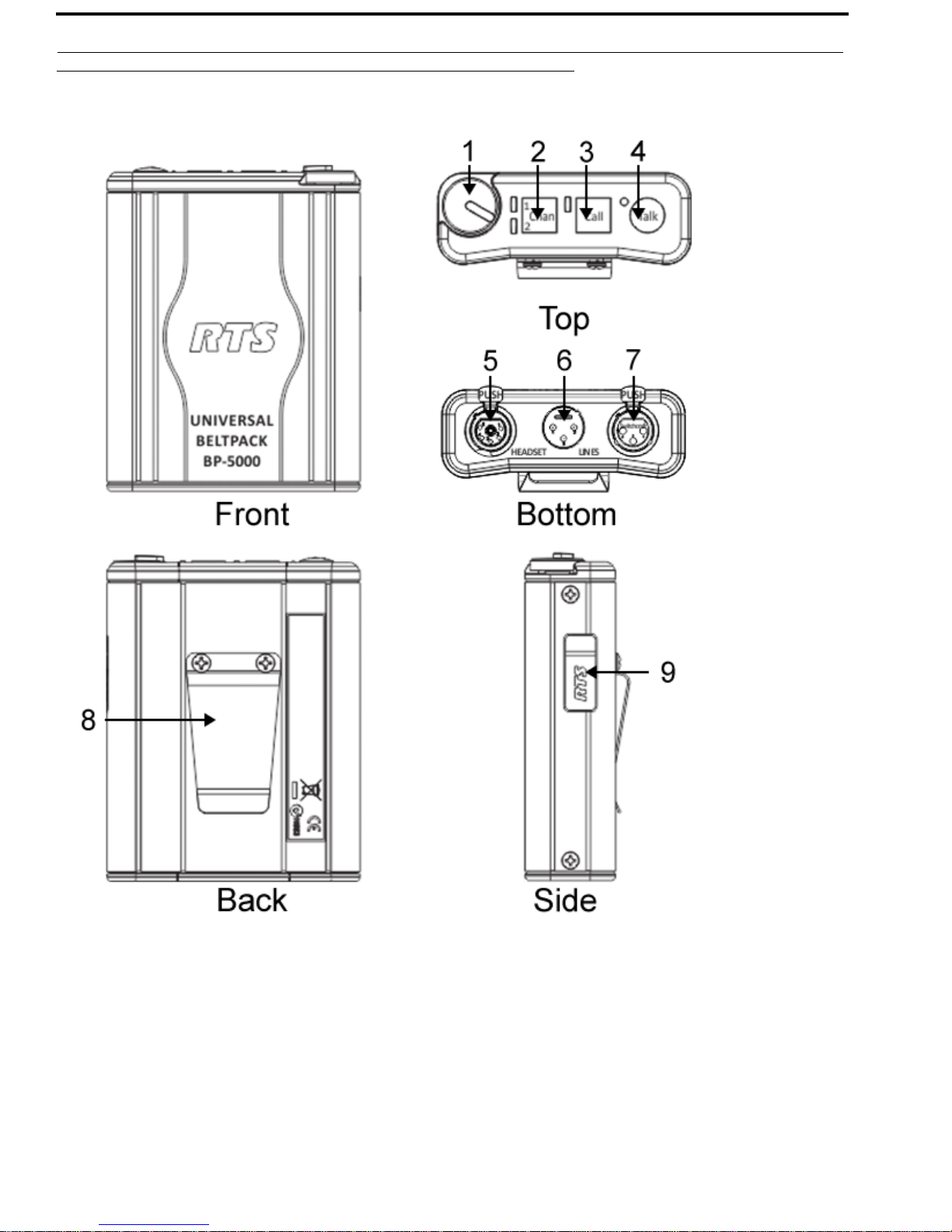
Reference View
FIGURE 1. Reference View
Page 9

Universal Beltpack Introduction 9
External Connections and Controls
NOTE: The numbers refer to the corresponding call-out numbers in Figure 1.
1. Volum e C o n trol: Use this control to adjust the headset/headphone listen level.
2. CHAN Select Button and Indicator Lights (BP-5000 only): Use the CHAN button to select the
available/active intercom channel. A blue indicator light displays next to the channel displaying
the active channel.
3. CALL Button and Indicator: The CALL button is used to send signals to other devices on the
selected intercom channel. The CALL indicator lights when any call is detected on the network.
4. TALK button and Indicator: The TALK button activates the headset microphone and operates
in either switched, momentary mode, always on, or always off. For more information, see“Talk
Mode Menu” on page 23
5. Headset Connector: The connector accepts an RTS headset with a boom microphone.
6. Line Connector: The BP-4000/5000 intercom channel is connected via a 3-pin female connector
and is powered through the intercom system power supply.
7. Loop Through Connector: The 3-pin male loop-through connector is used to daisy-chain up to
40 beltpacks on one power supply.
8. Belt Clip: The belt clip securely attaches to clothing.
9. USB Connector: The USB connector is used for service only.
Page 10
10 Introduction Universal Beltpack
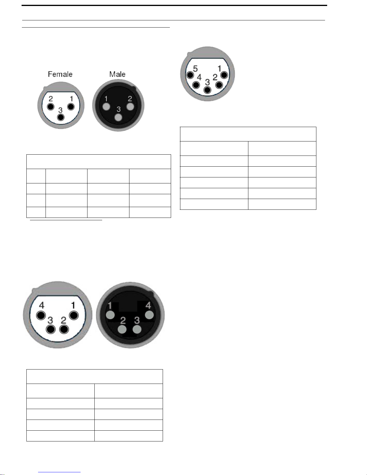
Connector Description
XLR (3-Pin)
XLR-3
Pin RTS Audiocom Clear-Com
1 GND GND GND
2
RTS CH 1
3 RTS CH 2 CH1 Lo Audio
a
CH1 Hi Power
XLR (5-Pin)
5-Pin XLR
Pin Description
1GND
2Mic IN
3 Headset +
4 Headset -
5 Headset -
a. BP-4000 Only – CH1 can be configured to either
pin 2 or pin 3. To configure the channel, see
“Channel Lock Menu (RTS Mode Only)” on
page 25.
XLR (4-Pin)
4-Pin XLR
Pin Description
1 GND
2Mic IN
3 Headset +
4 Headset -
Page 11

Universal Beltpack Introduction 11
Specifications
Power Requirements
a
Max. Operating Current (unbalanced)
45 mA
Max. Operating Current (balanced)
52 mA
Channel Supplied
18–33 VDC
Local Power
18–33 VDC
Environmental
Operating Temperature
32° F to 131° F (0° C to 55° C)
Operating Humidity
5% to 95%, non-condensing
Storage Temperature
-4° F to 158° F (-20° C to 70° C)
Storage Humidity
15% to 90%, non-condensing
Dimensions
3.75” W x 1.35” D [1.55” D w/beltclip] x
4.69” H [4.79” H w/top panel button]
95.2 mm W x 34.2 mm D [39.4 mm D w/
beltclip] x 119.2 mm H [121.6 mm H w/top
panel button]
Noise Contribution
<-60 dBu
Total Harmonic Distortion
<1.0%
Terminating Impedance
Balanced
300
Bridging Impedance
>10 k
Call Signaling
Send
20 kHz
Receive
20 kHz
Mic Off Frequency
Send
24 kHz
Receive
24 kHz
Unbalanced Intercom Channel
Output Level
0 dBu nominal
Frequency Response
Interface Requirements
Headset
50 to 200 (dynamic)
1 k to 13 k (electret)
Microphone Output Adjustable
max. 15dB (3dB per level)
Headphones
50 to 600
Balanced Intercom Channel
Output Level
0.0 dBu nominal
Frequency Response
200Hz – 8kHz
200Hz – 8kHz
Terminating Impedance
200
Noise Contribution
<-60 dBu
Total Harmonic Distortion
<1.0%
Bridging Impedance
Unbalanced
>10 k
Page 12

12 Introduction Universal Beltpack
Call Signaling
Send
20 kHz/DC
Receive
20 kHz/DC
Total Harmonic Distortion
<1.0%
Headphone Amplifier
Maximum Output
>140 mW into 150 load
Frequency Response
200 -8 kHz ±3dB
Audible Alert
1 kHz
Total Harmonic Distortion
<1.0%
Sidetone
>13 dB dynamic adjustment range
Crosstalk
Applicable to the BP-5000 in RTS mode with
2 channels.
<-60dB
a. Proper beltpack operation includes the use of a
power supply which has been tested and listed at
a recognized safety test laboratory.
Safe operation requires that a power supply be
selected which supports the maximum current
required for the total number of beltpacks on the
system.
Page 13

Universal Beltpack Introduction 13
System Configuration and Power
System Configuration
The BP-4000 and BP-5000 are capable of operating in three different modes:
RTS Mode – Unbalanced, shared power and audio
Audiocom Mode – Balanced, shared power and audio
Clear-Com Mode – Unbalanced, separate power and audio
Balanced and Unbalanced refer to the type of audio signal being used on the beltpack.
Unbalanced Audio – Uses ground reference signalling.
Balanced Audio – Uses differential mode signalling.
Power
The BP-4000 and BP-5000 use an external power supply unit, such as a PS-20, PS-31, PS-4001, etc to
power the beltpacks. Power is passed through the beltpacks via the Intercom Channel Connector (See
Figure 1 on page 8). Depending upon cable length, up to forty beltpacks can be daisy-chained together
running off the same power supply.
Channel Power
The external power supply provides power to the beltpacks in the system via the channel connector on the
power supply and the beltpack. Two power supplies can be used to run a large system or a system that has
a long cable run between sets/banks of beltpacks. Using multiple power supplies can evenly distribute
power throughout system. In a two power supply system, the local power setting on the beltpack is
commonly used.
Page 14

14 Introduction Universal Beltpack
FIGURE 2. Single Power Supply System
Page 15

Universal Beltpack Introduction 15
FIGURE 3. Two Power Supply System
Page 16

16 Introduction Universal Beltpack
FIGURE 4. Two Local Power Settings in a System
Local Power
The Local Power setting is used to isolate the DC power (voltage) so line noise is reduced without losing
signal voltage. Use the local power setting when you have two power supplies feeding a system of
beltpacks over a long distance (up to 1000 feet supported). For information on how to set local power, see
“Set Local Power” on page 31.
IMPORTANT: When using the local power setting only one beltpack in the line should be set to LP
(Local Power). Commonly, the first beltpack after a long cable run is set to LP, as
shown in Figure 3. In a two power supply system, if two beltpacks are set to local
power, then any beltpacks in between those two devices do not receive power (see
Figure 4).
Page 17

CHAPTER 2
Initial Setup and Configuration
Initial BP-4000/5000 Setup
The BP-4000/5000 has a mode-sensing setup built into it. Mode-sensing detects the system configuration
and then sets the beltpack to run in this mode. Mode-sensing setup is activated by pressing a sequence of
buttons on the beltpack.
The mode of the BP-4000/5000 needs to be correctly reconfigured either through mode-sensing setup or
the program menu. The mode can be verified by the sequence of flashing LEDs upon power up or
through the program menu.
NOTE: Using the mode-sensing setup on pre-configured beltpacks does not change any of the
programmable settings.
The factory setting for the BP-4000/5000 is RTS mode. For more information on the different modes of
operation, see “System Configuration” on page 13.
Page 18

18 Initial Setup and Configuration Universal Beltpack
UBP (Universal Beltpack) Initialization Troubleshooting Table
Unpredictable beltpack and system operation can occur if the BP4000/5000 is configured to a mode that
does not match the operational mode of the network power supply and/or the associated master station.
Behavior After Power-On Issue Resolution
• TALK and CALL buttons
do not work and
associated LEDS do not
light.
• Unit cannot access
PROGRAM MENU.
• While connected to the
network, the beltpack
may produce repeating
sets of audible clicks as
initialization attempts are
made.
All LEDs on UBP flash
constant
UBP is configured to
power-on to a specific channel and no
power is present
EXAMPLE:
• RTS UBP is configured for power
on CH 1 and is plugged into a
network with power only on CH 2.
• Clear-Com UBP is plugged into an
RTS network with power only on
CH2.
• RTS UBP is configured for power
on CH2 and then is plugged into a
Clear-Com network or RTS network
set for power on CH1.
• Audiocom UBP is plugged into a
Clear-Com network or RTS network
which has power on only one
channel.
UBP is designed to operate on networks
with valid line voltages of 18Vdc–
33Vdc. Unit is detecting voltages
outside of the expected range.
Perform mode-sensing setup to restore unit to proper
operation, see “ModeSensing Setup” on page 19.
• Validate network for
proper operating line
voltages.
• Perform mode-sensing
set-up to restore unit to
proper operation, see
“Mode-Sensing Setup”
on page 19.
IMPORTANT: Mode-sensing setup can only be done using a hot plug of the UBP into an already
powered network. Mode sensing is not reliable when done in conjunction with
enabling power to an entire network using a switched power supply or master
station. The voltage ramping characteristics of a switched power supply during
power up do not allow the UBP to reliably determine the mode of the network
IMPORTANT: In a Clear-Com system setup, the first beltpack MUST be manually configured to
enable the mode-sensing setup feature for subsequent beltpacks.
Page 19

Universal Beltpack Initial Setup and Configuration 19
Setup Mode Indication
When power is applied to beltpack, the LED lights blink to indicate the setup mode it is currently
running.
RTS – LEDs blink three times in three seconds
Audiocom – LEDs blink six times in three seconds
Clear-Com – LEDs blink nine times in three seconds
Mode-Sensing Setup
To enter mode-sensing setup on the BP-4000/5000 belt pack, do the following:
1. Connect one end of the XLR connector to the power supply or the powered network.
2. Press the CALL and TALK buttons simultaneously and plug the other end of the XLR
connector into the beltpack unit.
The beltpack detects the type of system to operate – RTS, Audiocom, or Clear Com.
3. Once the beltpack LED indicators start to blink, release the CALL and TALK buttons.
NOTE:
• If the beltpack is powered on without pressing the CALL and TALK buttons, it operates in
the last known system configuration.
• By default, the beltpack is configured for RTS mode.The headset microphone is auto-
sensing, which means it automatically determines if an Electret or Dynamic headset is
attached to the unit.
Firmware Version
Knowing the version of firmware running on the beltpack can assist a service technician to better
troubleshoot problems on the beltpack, if needed. When the beltpack has power applied to the unit while
pressing the TALK button, a voice prompt is heard in the headset saying the firmware version currently
installed.
To check the firmware version of the beltpack, do the following:
1. Verify the beltpack does not have power connected.
2. While pressing the TALK button, plug the power cable from the power supply or powered
network to the Intercom Channel Connector located on the bottom plate of the beltpack (see
Figure 1 on page 8).
[voice prompt] “X.X.X “(where X represents the firmware version).
Page 20

20 Initial Setup and Configuration Universal Beltpack
Programming the Beltpack
Enter Program Menu
To enter the program menu, do the following:
1. Put the headset on your head.
2. Press and hold the TALK and CALL buttons simultaneously for three seconds.
IMPORTANT: The beltpack must detect both buttons pressed together within 1/2 of a second. If the
TALK and CALL buttons are pressed more than 1/2 second apart, the PROGRAM
MENU is not entered.
3. Release both buttons.
The CALL and TALK LED indicators blink once and then stay lit.
[voice prompt] “Program Menu, Mode”.
4. Press the CALL button to navigate through the voice prompt menu.
Voice prompts are heard at every press of the button listing the available menu options.
5. Press the TALK button to select the desired menu.
6. Exit the Program Menu.
NOTE: After 15 seconds of inactivity, the beltpack automatically exits programming mode and no
changes are saved. Each time the intercom system power is turned on, the beltpack resets to
the previous program settings.
Exit Program Menu
NOTE: You must exit the program menu for any of the configuration modifications to take effect.
• If the Program Menu times out and closes, any modifications made are not implemented.
• If an incoming call is received while in the Program Menu, the beltpack automatically
exits the Program Menu without saving any modifications.
To exit the Program Menu, do the following:
> While in the Program Menu, press and hold the TALK and CALL buttons simultaneously for
three seconds.
The CALL and Talk indicators blink once and then turn off.
[voice prompt] “Exit”
IMPORTANT: The beltpack must detect both buttons pressed together within 1/2 of a second. If the
TALK and CALL buttons are pressed more than 1/2 second apart, the PROGRAM
MENU is not exited.
Page 21

Universal Beltpack Initial Setup and Configuration 21
Menu System
Page 22

22 Initial Setup and Configuration Universal Beltpack
Mode Menu
The Mode menu is used to select the configuration of the beltpack.
IMPORTANT: The first time the TALK button is pressed for a specific menu function, the UBP
voice prompt repeats the current setting of the unit. This allows the user to hear the
current setting of the menu option without changing the setting.
Available menu options are:
RTS (d)
Audiocom
Clear-Com
To select the Mode, do the following:
1. While in the program menu, navigate to Mode.
[voice prompt] “Mode”.
2. Press the TALK button.
[voice prompt] “RTS”.
OR
Press the TALK button again.
[voice prompt] “Audiocom”.
OR
Press the TALK button again.
[voice prompt] “Clear-Com”.
3. Exit the Program Menu (see “Exit Program Menu” on page 20).
The LEDs flash to indicate the mode the beltpack is programmed. See “Setup Mode Indication”
on page 19.
Page 23

Universal Beltpack Initial Setup and Configuration 23
Talk Mode Menu
The Talk Mode menu is used to program how the TALK button operates.
Available menu options are:
Switched (d) – The TALK button toggles on and off as long as the button press is less the 400msec. If
the TALK button is held longer, the button does not latch on.
Press the TALK button to turn on. Press the TALK button again to turn off.
On – The TALK button is always on. Talk cannot be turned off even when a mic kill signal
is sent.
Off – The TALK button is always off.
Momentary – If the TALK button is held for longer than 400msec, the beltpack enters momentary
mode. TALK is only active as long as the button is held.
To program TALK mode, do the following:
1. While in the program menu, navigate to Ta l k Mode.
[voice prompt] “Talk Mode”.
2. Press the TALK button.
[voice prompt] “Switched”.
OR
Press the TALK button again.
[voice prompt] “Off”.
OR
Press the TALK button again.
[voice prompt] “On”.
OR
Press the TALK button again.
[voice prompt] “Momentary”.
3. Exit the Program Menu (see “Exit Program Menu” on page 20).
Page 24

24 Initial Setup and Configuration Universal Beltpack
Mic Gain Menu
The Mic Gain menu is used to set the mic gain for the beltpack. Mic gain adjusts the audio level being
sent out on the line.
Available options for this menu are 1, 2, 3, 4, and 5.
1 represents the lowest gain setting, while 5 represents the highest gain setting.
The default for this menu is 4.
A mic gain setting of 4 sets the output to 0dBu, given a -45dBu nominal input on a dynamic microphone.
To configure the mic gain, do the following:
1. While in the program menu, navigate to Mic Gain.
[voice prompt] “Mic Gain”.
2. Press the TALK button to navigate to the desired gain level.
[voice prompt] “<gain level X>”.
3. Exit the Program Menu (see “Exit Program Menu” on page 20).
Sidetone Adjust Menu
The Sidetone Adjust menu is used to set the amount of sidetone heard through the headphones. Sidetone
is the effect of sound picked up by the microphone and then sent to the same headset.
Available options for this menu are 1, 2, 3, 4, and 5.
1 represents the lowest sidetone level, while 5 represents the loudest sidetone level.
The default for this menu is 1.
To configure the sidetone adjust, do the following:
1. While in the program menu, navigate to Sidetone Adjust.
[voice prompt] “Sidetone Adjust”.
2. Press the TALK button to navigate to the desired sidetone level.
[voice prompt] “<sidetone level X>”.
3. Exit the Program Menu (see “Exit Program Menu” on page 20).
Page 25

Universal Beltpack Initial Setup and Configuration 25
Incoming Call Beep Menu
The Incoming Call Beep menu is used to enable and disable whether a beep is heard in the headset when
a call comes into the beltpack.
Available options are On or Off.
The default for this menu is Off.
To configure incoming call beep, do the following:
1. While in the program menu, navigate to Incoming Call Beep.
[voice prompt] “Incoming Call Beep”.
2. Press the TALK button to enable Incoming Call Beep.
[voice prompt] “On”.
OR
Press the TALK button to disable Incoming Call Beep.
[voice prompt] “Off”.
3. Exit the Program Menu (see “Exit Program Menu” on page 20).
Channel Lock Menu (RTS Mode Only)
The Channel Lock menu is used to program whether the BP-5000 has access to one or two channels. It is
also used as a method to switch channels on BP-4000
Available options are Channel 1, Channel 2 or Off.
The default for the BP-5000 is Off.
The default for the BP-4000 is Channel 1.
To configure channel lock, do the following:
1. While in the program menu, navigate to Channel Lock.
[voice prompt] “Channel Lock”.
2. Press the TALK button to select Channel 1.
[voice prompt] “Channel 1”.
OR
Press the TALK button twice to select Channel 2.
[voice prompt] “Channel 2”.
OR
Press the TALK button three times to select Reset.
[voice prompt] “Off”.
3. Exit the Program Menu (see “Exit Program Menu” on page 20).
Page 26

26 Initial Setup and Configuration Universal Beltpack
Power Source Menu (RTS Mode Only)
The Power Source menu is used to select which channel the beltpack draws power. By distributing the
power draw, more beltpacks can be used on the same party-line.
Available options are Channel 1 or Channel 2.
The default for this menu is Channel 1.
To configure the power source, do the following:
1. While in the program menu, navigate to Power.
[voice prompt] “Power”.
2. Press the TALK button to select Channel 1.
[voice prompt] “Channel 1”.
OR
Press the TALK button twice to select Channel 2.
[voice prompt] “Channel 2”.
3. Exit the Program Menu (see “Exit Program Menu” on page 20).
Mic Kill Menu (RTS and Audiocom Mode Only)
The Mic Kill menu is used to enable or disable the ability to ignore a Send Mic Kill signal sent to turn off
the mic on the beltpack.
Available options are On or Off.
The default for this menu is On.
To configure mic kill, do the following:
1. While in the program menu, navigate to Mic Kill.
[voice prompt] “Mic Kill”.
2. Press the TALK button.
[voice prompt] “On”.
OR
Press the TALK button again.
[voice prompt] “Off”.
3. Exit the Program Menu (see “Exit Program Menu” on page 20).
Page 27

Universal Beltpack Initial Setup and Configuration 27
Send Mic Kill Menu (RTS and Audiocom Mode Only)
The Send Mic Kill menu is used to send a mic kill signal to shut off a microphone on a beltpack , user
station, or master station that has been inadvertently left on. A 24 kHz signal is sent to the party-line
where the beltpack with the microphone left on, signalling it to shut off.
Available options are Yes or No.
IMPORTANT: The Send Mic Kill is not sent until the beltpack has exited the program menu.
The program menu must be exited before the mic kill signal will be sent.
To send a mic kill, do the following:
1. While in the program menu, navigate to Send Mic Kill.
[voice prompt] “Send Mic Kill”.
2. Press the TALK button.
[voice prompt] “No”.
OR
Press the TALK button again.
[voice prompt] “Yes”.
3. Exit the Program Menu (see “Exit Program Menu” on page 20).
LEDs Menu
The LEDs menu is used to set the LEDs to normal intensity or dimmed on a beltpack.
Available options are On or DIM.
The default for this menu is On.
To configure LEDs, do the following:
1. While in the program menu, navigate to LEDs.
[voice prompt] “LEDs”.
2. Press the TALK button.
[voice prompt] “On”.
OR
Press the TALK button again.
[voice prompt] “DIM”.
3. Exit the Program Menu.
Page 28

28 Initial Setup and Configuration Universal Beltpack
Factory Reset
The Factory Reset menu is used to reset the beltpack to its original, factory settings.
Available options are Yes or No.
The default for this menu is Off.
To perform a factory reset on the beltpack, do the following:
1. While in the program menu, navigate to Factory Reset.
[voice prompt] “Factory Reset”.
2. Press the TALK button.
[voice prompt] “No”.
OR
Press the TALK button again.
[voice prompt] “Yes”.
3. Press the CALL and TALK buttons simultaneously.
The CALL and TALK indicators blink once and then turn off.
[voice prompt] “Exit”
The LED indicators blinks the number of times associated with the mode it is in (see “Setup Mode
Indication” on page 19). The beltpack is reset to factory defaults.
Page 29

Operation and Maintenance
Operation
Adjust the Volume
To adjust the volume on the beltpack, do the following:
CHAPTER 3
> On the top panel of the beltpack, turn the volume knob clockwise to increase the volume.
OR
Turn the volume knob counterclockwise to decrease the volume.
Change the Channel (BP-5000)
To change the channel on the beltpack, do the following:
> On the top panel of the beltpack, press the CH 1/2 button once.
The active channel is toggled between CH1 and CH2.The blue LED indicates the active channel.
Page 30

30 Operation and Maintenance Universal Beltpack
Maintenance
Replace the Beltclip
To replace the beltclip on the beltpack, do the following:
1. Using a screwdriver, remove the two locking washers and screws holding the beltclip in place.
Set the washers and screws aside for later use.
2. Remove the beltclip from the unit.
NOTE: Take care to keep the O-rings for later use.
3. Using the existing washer, screws and O-rings, reattach the new beltclip to the beltpack.
Page 31

Universal Beltpack Operation and Maintenance 31
Set Local Power
Local Power is set by shorting pins on the J4 jumper located on the PCBA board. The board must be
removed from the beltpack housing to make this adjustment. For more information on Local power, see
“” on page 15.
To set local power, do the following:
1. Remove the two side screws from the beltpack unit.
IMPORTANT: There are two red o-rings to strengthen the seal and keep moisture out of the beltpack.
Keep these o-rings with the screw. They can sometimes become lodged in one of the
screw holes.
2. Carefully slide the top plate assembly from the beltpack enclosure just far enough to expose
the entire PCBA board. Take care not to disconnect the connectors from the headers.
Page 32

32 Operation and Maintenance Universal Beltpack
3. Being careful not to pull the connectors from the headers, attach jumpers to J4 on the board, as
described in Table 1.
IMPORTANT: If you need to move the connector wires to access the J4 jumper, gently push them to
either side.
TAB LE 1. J4 Jumpers
Normal Local Power
Pins 1&3 and Pins 2&4
shorted
4. Carefully slide the top plate assembly into the beltpack enclosure.
5. Using the provided screws and O-rings, replace the side screws.
IMPORTANT: To ensure the beltpack is properly grounded when reassembling, fully tighten the
Pins 3&5 and Pins 4&6
shorted
screws on one side of the unit, and then fully tighten the screws on the other side of the
unit.
Page 33

Universal Beltpack Operation and Maintenance 33
Notes
Page 34

34 Operation and Maintenance Universal Beltpack
Notes
Page 35

Universal Beltpack Operation and Maintenance 35
Notes
Page 36

Bosch Security Systems, Inc.
12000 Portland Avenue South
Burnsville, MN 55337 U.S.A.
www.boschcommunications.com
 Loading...