

Page 1
USER
I
MODEL
MANUAL
BP317
I
Portable Belt Pack User Station
:
9350-5435-00
Rev
Dl
1/95
RTS
'"
Page 2
PROPRIETARY NOTICE
CUSTOMER SUPPORT
The RTS product information and design disclosed herein
were
originated
Communications,
pqnktary
sales
rights thereto, and
except
to
by
and
are
Inc.
design, manufactlning, reschofn, useand
the extent rights
the properly of Telex
Telex
reserves
to
any article d~sclosed
are
expmsly
all
granted to
therem,
others.
COPYRIGHT NOTICE
C fight 1994 by Telex Communications, Inc..
rigts
resaved
prior
written pernussion from Telex
Reproduction in whole or in
is
prohibited
part
AU
without
PATENT NOTICE
This equipment contains and uses a desi n embodied in
United
States
Source for a Multi-terminal Intercom". This design
Patent No. 4,358,644: "A
employs a two-wire to fow-wire converter.
kilateral
Current
UNPACKING AND INSPECTION
Immediately upon receipt of the equipment. inspect the
shipping conmer
discrepancies or damage. Should there
freighi company and fie dealer at once.
and
the wnttnts carefully for an
be
any, not& the
WARRANTY INFORMATION
RTS products
Inc. to
for a period of
The sole obli~ation of Telex dmina the wanantv oeriod is
to provide, without charge, parts aiid
remedy covered defects
pre aid
de&t, malfunction
of Telex, including unreasonable or neglisent operation,
abuse, accident, falure
Senrice
improper associated equipment, alt&npts modification
and repair not authorized by Telex, and sh~ ping damage.
Roducu wlth theu serial numbers remov
not covered by this warranty.
are
be
bee
to
Manual
warranted by Telex Communications.
from defects in materials and workmanship
three
years from
Telex. This
or
or
the User Manual. defective or
appearin
wananty
failure
to
the
date
of sale.
labor
in products returned
&
not cover any
caused
beyond the control
foUow inSmr.hons
ei
n&&y to
in
the
or effaced
are
Technical questions should be directed to:
RETURN SHIPPING INSTRUCTIONS
If
arepair
was purchased.
If
re
&
DO NOT
TO THE FACTORY
OBTAINING A RETURN AUTHORIZATION.
Be
phone number, a person
the
problem and the send number(s).
SHIPPING
ADJUSTMENT
All shipments of RTS products should be made via
United Pmcel Service or
p
&
container
containa is
paper
excelsior
ship"
inc ude
is
necessary, contact the dealer where
air
throu h the dealer is not possible, obtain a
A&HORIZATION from:
Customer Service Deoartment
~
~
Telex ~ommun$ions, Inc.
Telephone: (800) 828-6107
Fax:
RETURN
prepared
type
and
TO
aid. The equi ment should
g carton;
that
and surrounded with at least four inches o
or
ents must
the
Rehm Authorization.
-~
(800) 323-0498
ANY
to
provide the company name,
quantity of
MANUFACTURER FOR REPAIR OR
i
?
,@t
is
ngld and of
used,
he equipment ihould
similar
shock-absorbing material.
be
sent
~r~-
~~ ~ ~~
E
WITH 8 UT
1s
.
UIPMENT
FIRST
to
contact regdng the repair,
equipment.
the
not available, use any suitable
to
the following address and must
a description of the
best available shipper,
be
shipped in the original
adeauate
sue.
be
this
DIRECTLY
address,
If
a substitute
wrap
ped
All
unit
in
To obtain warranty service, follow the procedures entitled
"Rocedure
for
Repair
This warrantv is the sole and exclusive exoress wanantv
given with &ect
responsibility of the user to determine before purchase
that this duct is suitable for the user's intended
NEITHER
RTS PRODUCTS IS
CONSEQUENTIAL DAMAGES OF
For R~ums" and "Shipping to Manufacturer
or
Adjustment".
to
RTS products. It 1s he
TELEX
NOR
THE
LIABLE
--
-
DEALER WHO SELLS
FOR INCIDENTAL OR
ANY
KIND.
Page
2
Upon completion of any re
retuned
vla
United Parcel getvice or specified shipper
air
the equipment will
be
Page 3
TABLE OF CONTENTS
pROrnARYNOTI(3E
COPYRIGHTNOT][CE
PArnNOn(3E
UNPACKINGANDINSPECnON
WARRAElTYINEDRMAnON
RETLJRNSHIPPINGINSTRUCIIONS
SECllON
1.lDESmON
12
BP317
SECllON
2.1
TYPE
22TYPEOFMOUNTNG
23CHOOSINGHEADSETS
2.4 CABLING REQUIREMENTS
1:
DESCRIPTION & SPECIFICATIONS
SPECIFICATIONS
2:
INSTALLATION
OF SYSTEM, POWJWNG METHOD
2.4.1WIRES5
2.42GROUNDING
2.43SIGNAL
............................................
.....................................................
........................................................
...............................................
.................................................
.......................................................
.................................................
................................................
...................................................
..................................................
...............................................
......................................................
.....................................................
........................................................
............................................
....................................
AND
POWER
SUPPLW(IES)
.....................
..
2
2
2
2
2
2
4
4
5
6
6
6
6
7
7
7
8
2.SMECHANICAL
2.6SYSTEMCHECK
2.7 STANDARD
SECTI0NI:OPERATION
3.1 OPERATING CONTROLS AND CONNECTIONS
320PERATION
DIAGRAMS
.......................................................
......................................................
USER
STATION CONNECTIONS
.....................................
..................................................
.........................................................
.......
.................................................
....................................
8
8
9
6
11
11
12
Page
3
Page 4

SECTION
DESCRIPTION & SPECIFICATIONS
The
usw
duplex, confemme
A confenwe line
people
channel,
usen
sham
Full duplex
the
user
1:
Uodcl
BF317
station.
This
usw
M
talk
and
all
users
are
talking
the
same confaence
operation
same time, that
while the second
is
a
patable,
station
he
intacom
intercom
listen
can
listen when one
(co1&~115ig). Up
allows two way condon at
is,
one user
usw
single-channel
is
designed
to
system.
system allows a group of
on
a
singIe
cha~~L
to
line
(or
conference bus),
can
intermpt a second
is
still
talking.
be
used
On
or
more other
75
nscrs
intacom
in
a
fan
this
can
In
ncumal
rest
talker's
tokeep
intelligibility
other
The
Themomentarypasitionallows
tion,
latched
user
another activity.
Model
Unmodified
1.
system
operation,
lkta.
A micauphone switch on
miaophone
theirtnicmphomM1dIn thisoondition,speech
microphones
microphone
(1)
center
(2)
momentary
(3)
latched
especially
posih
needs
to
BP317
BP317
An
XLR4
microphone headset or handset.
to
is
enhanced
is
switcb
"OFF",
"ON".
mful
allows
have.
two
Connections, Inputs & Outputs
usw
type female connector for a dynamic
one
or
more
users
each
station allows
be
enabled
not
pmmt
has
"ON",
in a
"hands
way
stations have
and
allows
since
background
three
positions:
and
quickbumsofcommunica-
high
noise environment
£fee" operation. when the
convedon while performing
two
connexm.
talk
and
the
listuras
noise
the
the
from
The
The
BP317
with
a
headset,
to
the
intercom system. The
headset
via
nects
type cable. The
ininterface
and
The volume control on the
cumpensate
variation, variations in headset I handset sensitivity, and
variations in talker voices.
reduces distortion by driving the headphone amplifier only
as much as needed.
(or
a
handset)
a four conductor fable and corntor. The
to
the system
BP317
well
to the inmm system: the volume control,
the
microphone
for.
user
in
effect, interfaces a human
user
tallcs
The
headset
using
a
three
contains two conmls
connects
conductor "microphone"
switch.
BP317
hearing differences,
The
has a wide
volume control in the
and
listens
using
to
the
BP317
to
help the user
ambient
uw
BP317
con-
range
noise
BP317
the
to
2.
An
XLR-3
the
Power
Reqninments
-\The
BP317
opaable
Power
is
using two different methods: (1) the
method,
Optional Features
User-instaUed options include:
connection,
opelalion.
BP317
The
the
Series
theTW
is found in Appendix A.
Intercom
type
femak
con-
communications line.
requires
at
reduced performance from
carried
or
(2)
the
to
the
three
from
unit
wire
+
15
to
+35
from
a system power supply
or
Series
carbon
two-wire
works with both the TWIntercom System and
17
Intercom System. Further information about
line opention, and two-channel
System
and
the Series
to
tie
the station
volts
DC,
+
12
to
+I49
TW
or
two
17
method.
microphone
17
Intmcm System
headset
to
but is
volts.
wire
line
Page 5
13
BP317 SPECIFICATIONS
Input DC Voltage
DC
18 to 35 volts
-)
(12 to 17 volts,
DC Cmnt
Quiescent
Operating, 10 dB
below dipping
ohm
headphones
25
'20
milliamperes
35
milliamperes
reduced
perfor-
Headphone Amplifier
Voltage
Onlput
Gain
Voltage
34
8 volts
1/2
HeadphoneImpedanceRange
25
to
600
ohms (500 to
dB
watt
2000
@-@peak
peak
with
into
25
into
25
ohms
reduced levels)
ohms
Impedance
10,000 ohms,
Across
Lie
minimum
Environmental
Temperature
operating
Storage
Humidity
Storage 5% to 95% non-condensing
&
Noise Contribution
One unit -75 dBu
Ten units -67 dBu
Microphone Preamplifier
Input Impedance 470 ohms/dynamic
Source Impedance 200
ohms,
nominal
Maximum Input
Level 150 millivolts
Frequency Response
(-54
dBu input) 100 hertz to 10 kilohertz
mi
f
3
dB
NOTE: DO NOT USE HEADPHONES WH
IMPEDANCES LESS THAN
Sidetone
Adjustment
Range
25
OHMS.
-2OdBtoNlon
Headset Connector
Dynamic Microphone XLR
type
4-pin female
Lie Connections
Input XLR
type
3-pin
female
Dhndoos
H
x
3.00
W
x
1.5P
D,
5.20
132
H
x
76
W
x
38
D,
inches
millimeters
Weight
1.1
pounds,
0.5 kilograms
Fi
Clear,
anodized
*Depth
with
SPECIFICATION NOTES:
aluminum I or textured grey paint
beltclip: 1.87 inchcs 147.5
mm
Limiter Range 30 dB
Carbon
Mic
(User
Option)
Excitation Cln~ent I0
Current Source
Transfer Ratio
Output
milliamperes,
milliamperes
3.3
=
3.3 millisiemens
i5
milliamperes into 200 ohms
=
f
1 volt peak, nominal
nominal
/ volt
Page 5
0 dBu
0
dBm
Note:
=
0.775 volts rms.
=
1
milliwatt
=
0.775 volts rms into
(0
dBu, open circuit)
M
products and specifications subject
600
change wilhout notice.
ohm load
to
Page 6

3.
Read
"Choosing
Headsets
or
Handsetsts (Section 23).
Follow the
2.1
'Ihe BP317
two
(1)
(2)
(3)
In (1) above,thepowersupply isaregulatedsupply.24 volts
DC
a2
amp
In case (2) above, the number of BP317s
by various
supply: 12; PSI%
In (3) above,alocalpowersupply needstopvide 18 to 24
volts
~~:
Type
Of
System,
Supplier(ii)
can
wire
system. a (3)
In
a
three
wire
sepate
power supply.
In
may
ly by a
In
BP317 is locally powered.
tem
to 32 volts
fmm
a two
wire
sharethesamewire.Ihepowerissmctntral-
special
a
special
are
interconnected using two
DC.
supply.
"TW"
DC
at
100
"To
Insall
the BP317". below.
Power@
be
installed in a
special
system
the audio and is supplied by a
system
CTW"
"lW"
typepower
two
wire
Up to 57 BP317s
Method
(1)
two
("Series 17" type), the
type),
system
and
And
three
wire
wire
system.
the
powa
supply.
(Lccal
the BP317s in the sys-
wire
can
be
that
powa
supplies
28.
PS31: 42.
milliamperes
are
peak.
as
follows: PS8 power
Power
system,
Power),
cable.
ope@ed
can
powex
central
and
audio
each
from
powered
(2)
is
4. Debermine
Create
5.
not already available), then install the
6.
Verify
pmcedme
7.
Update
any other documentation to
configuration. If the system block diagram was
originally
"as
This
documentalion. and
(1) One type of mounting for the BP317 is patable, when
it is worn on dothing
has
(2) Another type of mounting for the BP317 is permanent
or
semi-permanent, either a
desk)
on
a
the
wanted noises on the intercom line.
2.3
Choosing
the
cabling requirements.
a
system
correct
the
block
system
in
Section 2.6.
system
diagram
operation
block
and equipment
by using the checkout
diagram,
reflect
created
installed"
diagram
a
Mt
clip.
or
fastened tofmniture. Avoid placing
metal
Model
system
will
cr
gmunded
BP317
by
RTS Systems, send
block
diagram
be
used to
for
future
service
or
an equipment belt. The BP317
"desk
metal surface. Contact between
and
metal
s~lrfaces may
Headsets
list
system.
equipment
the
to RTS Systems.
update
suppon.
mount" (sitting on a
list
and
"as
installed"
a
copy
of
the original
the
BP317
cause
un-
the
(id
In (1) and (3) above.the two
one system terminaton consisting of a200
a 100 microfarad/50 volt capacitor in series.
tion is connected
polarized its negative
circuit common.
To
Install
1. Determine the type of
installed.
be
power supply(ies).
Determine
2.
Permanent.
across
the
BP317:
Determine the powering
the mounting of
wires
the two
teaminal
system
canying
wires.
is connected to the system
in which the BP3 17 is to
the
the
ohm
If
BP317: Portable or
audio require
resistor
This
the capacitor is
method
and
combina-
and
hfmiwt&
vironment, operating requirements,
ODn;ltinnEnvimma& Table 2-1 shows typical operating
envinnunents and the amount of background noise present.
A
very
quiet operating environment may require
does
not
phones
very
A
phones
good
acoustic
loud, clear
well.
Headset choice depends on operating en-
and
personal
leak
from
fhe
headphones, meaning the head-
should
have
good "acoustic isolation".
noisyhoud environment usually
that
prevent
sound,
dde
isolation), headphones that can produce a
and noise cancelling microphones,
sound
from
leaking in (ngain,
taste.
that
requires
sound
head-
as
Page 7

Undexstanding speech in a noisy environment
the
wanted sound from
than
the unwanted
the
noisy environment.
I,mdw%
upon its ab'ity to
peaanCe) and
impedance
In
general the loudness of a headphone
the
has
a
the
hexbhones
sound
leaking
abxab
pwer
efficiency of its design. Practically,
larger effect with present day headsets.
is
as
loud
into the headphones
at
a given wltage
requires
or
louder
depends
that
limn
(m-
the
The DTlBDT109 hudsets have an isolation ranging from
10
dB
tom
dB.
At least four companies: Telex, Setcom, David
Carts
Engineering
dushial,
can-provide
Generally speaking, these headsets
comfntable to
aerospace,
mustic isolation
wear.
sell
headsets intended for heavy in-
and
military markets.
figures
of
are
Clark,
and
These
headsets
2OdB
to 40dB.
heavier and less
Imoedance.
ingtheBP317todraw
Hirgh
nment from
Low
impdance
the
impedance headphones
morecun'entfmnthepo~ers~1~.
headphones
power supply. The BP3 17
an
not
are
louder,
as
lm& drawingiem
Mgn
range
caw-
of
In
high noiseenvimmnents, the headset microphone should
be
a noise cancelling
impedancesfwtheheadphonepratoftheheadsetis25ohms
to
600
ohms. Headphoms up to 2000 ohms
at
reduced levels.
DT109 sold by RTS Systems, there
connected in parallel resulting in an impedance of25 ohms.
Efficiencv.
impedance headphones such
phone, one
SPL
(Sound
dB in each
=&
cause the BP317 to require mwe powex
supply. With
milhamperes. With
30 milliamperes. (Quiescent BP317 current
Ilamperes.
In
a double muffheadset such
The BP317 produces the loudest sound in low
as
the DT109.
milliwatt of electrical power produces
Pressure
ear
DT109 headsets, BF'317
Level).
BF'3
17
The
of a DT109 w DT108 headwi Low im-
as
600
headphones.BP317
can
the DTlO8 and DTlW headsets,
will
function but
as
the
are
50 ohm headphones
In
this
produce
an
fmn
peak
current is 75
peak
SPL of
the power
current is
is
20 mil-
Beyer
head-
94
dB
Ill
-In
their weight, padding and design.
2.4.
Cabling
2.4.1
Wire
It may
be
conductor
Normal
maximum
powex supply voltage,
minimum
equals
minimum
current
Example: A BF'317 headset station (with 25 ohm headphones)
power supply voltage
conductor
the
(pwerrequhd by the
uses
minimum
The ability of headphones to shut out unwanted environ-
varies
from
mental noise
as
loud (30
both on the design of
of
the
such
(double muff), have almost no (0 dB) isolation.
off is that
be
worn for long
discomfort from the earmuffs or headband. The
LH267bH268
loud.
Because there
sound signals
ally leaked into micmphones.
dB
isolation).
environmental noise. Lightweight, "open" headsets
as
the RTS Systems LW67 (single mu@ and I33268
the
LH267/LH268
are
is
from
none (0
the
periods
low
impedance
no isolation,
the LH267bH268
dB
isoktian)
The
dep
of isolation
headset
and
the frequency content
are
very comfortable and
(8
to
12 hours) without physical
and
can
we
must
be
are
not unintention-
to
about nth
depends
The
be
turned up
Iaken
that
bade-
can
the
impedance).
=
(26-18) volW.035 amperes = 228
'Ibis
cmespnds
(7.125 feet) for a
station with25ohm headphones. Datafor thesecalculations
can
be
found in
ard
electrical
2.42
Grounding
System circuit ground should not
"tarth"
w
tion an ohmmeter would show).
bypased
establishing aradio frequency
frequency interference from radio transmitters.
type.
general, the comfort of headsets depends upon
Requirements
Size
necessary
size
allowable loop resistance is
operating voltage. The
difference
operating voltage divided by the maximum loop
operating voltage is 18 volts
"chassis" ground (wheredirectly meansaconneo
to its own chassis via a 0.1 microfarad capacitor,
to
overcome power losses by increasing
over long nms (more
size
is
#22
AWG (16 ohm/lOOO ft.).
the
loop current and the
of
the
power supply voltage and the
35 milliarnpres
Then
the
maximum allowable loop resistance
to
an operating distance of 2192 meters
#22
the
specifications in section 1 and in stand-
wire
tables.
at
is
26
volts
AWG wire
than
one kilometer).
deVrmi
maximum
user
station(s)).
10
dB
DC
ohms.
pair
be
CRF)
loop resistance
below clipping.
and the
DC
using a single
directly connected to
Each user station is
ground
to
The
by the
user
station
The
user
station
(for bridging
user
reduce
radio
Page 7
Page 8

In
0rde.r
to prevent a buildup of
capacitance, the power supply
chassis ground
power supply, a bleeder
central point in
The basic bdt
return
circuit
an
accidental ground faalt
ing
can
happen
cable
that
accidental
fault
can
can
fault
(22
kilohms).
redstor
the
system.
of
not
"earth"
is
that
it pennits
as
the
result
of a
has
been
pulled
across
ground
be cleared and
cause noise or ovaload orbring the
can
be
Ideated
(with
luck)
Muage
has
If
gromding
continued
pinched
aaoss
a bleeder
the system
should be supplied
the
opedon dming
This
accidtntal
wire
a
sharp
edge.
by the
system
befon
a
second
system
the system
resistor
has
no
RTS
System
ground-
or
a
scraped
A
single
until
ground
down.
to
RTS
at
the
The
200
ohm
line
impdance
comm~on over line lengths of
mile) and low enough to permit
a
bandwidih with
most systems the
bandwidth with low
When
using equipment in rain or conditions of excessive
moishne,
make
and
3.2
kilometers of accumulated cable.
200
ohm
losses.
always protect the equipment
sun
all cable connectors
is
high enough to allow
an
impedance
m
1.6
kilometers
adequate speech
gives a high fidelity
with
plastic covers
liffed
out of mud,
(one
In
snowormoishneand~tedmthplastic.Watcl'mudand
snow in connectas
can
cause considerable hum.
Another hetit of not
is
that
it pvents the intduction of noise through
currents from other equipment
conducts these cmts, it
as
interfering noise on the communication
Zd.3
Signal
The number of conductors
stations
Number of
is:
Conductors
Two channel
wire
applications may use either
(for convenience) or
less expensive
for the
paman&t
should have individually
gauge
- -
reduceint&erenceand help maintain a low cmsstalk figure
between channels.
interference.
used.
"TW"
than
system
is
installatio~it&recommcndedthat~hchannel
wire.
such
Umhielded cable
"earth"
grounding the drcuit
If
the
is
likely
that
required
Number of
RTS
circuit ground
they
will
line.
to intexcmect user
i2haM&
applications, a single channel,
standard
two-twkted-pair
miaqhone cable).
#22
gauge
wire
shielded
as
Belden #87U fa 2 channels.
In
genaal, shielded cable will reduce
can
miaophonecable
cable (considaably
Standard
for intemnnection For
twisted
pair
of
often be sdully
IC~
"earth"
be heard
three
wire
size
at
least
#22
'Ibis
will
user
The BP317
forportable operation, or mounted on asmcture, camera or
vehicle.
For permanent installation, temporarily remove the
deckmica
as
necessary, then
inshudions
An
insrallaton drawing fa headset
included at the end of this section. These drawings provide
mechanical
installations.
fastener hole locations, console cutout dimensions and
weights.
Space allowances for control access. cabling and serviciig
must be
It
hce
powa
cables.
If
this cable and interfering sources such as videom
monitors, power supplies and equipment with
power supplies.
2.6
-ned
is
recommended
loops,
option power supplies and headset connectors and
the headw connector is remoted. allow
System
station is either clipped to a user's clothing
fmm
the
we.
Drill,
debm and
reinstall
on
how
information useful forpermanent and other type
This
information includes overall dimensions,
caching
the electronics. See Section 5 for
toremove the electronics from the
on a
case
by
case
that
space
be
provided
XLR
flpe
connector
fasten
the case
case.
user
station BP317 is
basis by the installer.
for: cabling
I&,
local
space
between
internal
Check
The audio signal line level is maintained between -10 dBu
and 0 dBu (between 0.24
are
low enough
(such
as
interference to the
TV
camaasf
to
and
0.77 volts rms).
prevent crosstalk
yet
high
enough to
TW
System.
nKse
into
other equipment
reduce
levels
extanal
Page 8
Using thmbeltpackswith
verify
all
persons
systek.
volumecontrols midway,
The other two persons should sound equally loud and clear
to the
V&
third
that
person.
three
headsetsand
can
intercommunicate bunhout the
with all microphone switch& off and
only
abarely audible
threepersons,
hiss
is heard.
Page 9

2.7
Standard
Dynamic Miaophone headset connector:
XLR-4-3
Input level
-55
dBu, nominal
Output level to hedphone
10 volts
-
Pin 1
Pin 2
-
Pin 3
-
Pin
4 -Headphone high
Do not common pins
Line input connector: J101)
XLR-3-3 1 receptacle (for singlechannel)
User
Station Conneetiom
1
type
(female 4pin) receptacle (J102)
peak-to-*
Miuuphone low
Miaophone high
Headphone low
open
1
and 3.
circuit
2-1
Table
Typical
Environmental
SQuCx
AimatlR
Orchestra 75 piece,
Organ.
Pipe
Rock
Concert 110dBto140dB
Piano,
Peaks
Blaring Radio
Cenhif'ugal
Auto on Highway
Vaneaxial Ventilating Fan
Voice, Shouting 90 dB
Factory
Voice, Conversational
Residence 45 dB
Television Studio 25dBto35dB
Voice,
whispa
Operating
Noise,
at
10
meters distance
(Peaks)
Pealis)
Ventilating
Environments,
Smnd
Ressure
or
Fan
Lcvel,
Seh,
1mdBto160dB
140 dB
120 dB
110 dB
110 dB
100 dB
90dB
75 dB
70 dB
30 dB
-
Common (low
Pin 1
Pin2-Power
-
Channel
Pin 3
XLR-3-31
Pin 1
Pin
Pin 3 - Channel 2 (Audio)
*
For opemion
modified May
using
channel 1) then tying pins 2 and 3 together at connector.
receptacle (for two-channel)
-
Common (low
2
-
Channel 1
line
cable
side
side
(+DC)
on
channel2 only
also
beopemted
with just two
of
line)
of line)
on
wires
or
both channels
channel
1
(canmon
by
connecting
and
if
TW
so
Table
2-2
Typical
SQUm
Maximum Allowable Impulse 140dB
Exposure
LH267
10 dB below Clipping
DT109
10
LHZ68 + BP317 llOdB
10 dB below Clipping
Setcom Series
10 dB below Clipping
Headphones with 20 dB Acoustic 11OdB
Isolation
(Mouth Closed)
Headphones with 40 dB Acoustic
Isolation at 140 dB
(Mouth Closed)
+
+
dB
below Clipping
Soolld
Operating
Prrsnrre
Environments,
Level,
at
Ear
SEL
BP317 114 dB
BP3U 111 dB
5
+
BP317 99 dB
at
130 dB Rock Concert
100 dB
Rock
Concert
Page 10

Figure
Front Panel, Model BP317 Portable Belt
3-1A
Pack
User
Station
Rear
Panel, Model BP317
3-18
Portable
Belt
Pack
User
Station
Page 11

-
SECTION
3.1
Operating Controls
Table 3-1 below
to the circled numbers in Figure 3-1.
Ref.
&
Front
Panel
3:
OPERATION
lists
the
&I.&
And
Connectio11~
Model
BP.17
user
station wntrok
and
connectas.
3w&l
me refaence numbers in Table 3-1 carespond
1
VOLUME control
MIC ON
toggle
Sets the sound listening level in
This
different MIC-ON pasitionx latching
&tim
Lff
be
Rear Panel
DYNAMIC
micro~hone
This 4-pin female
microphone type
INTERCOM
("line") conneetor
3.2
Operation
To communicate
directly
INPUT
with
another
station
or
This
Twsystemorsaies 17line.
stations:
1) Turn the volume control all the way counterclockwise
2)
Set the
MIC
ON/OFF
toggle switch to one of
the
"OW
switch must be on before the microphone switch on the headset
3)
Set
the
listening level in the headset using the Volume conml.
the
user station headset headphones.
thtteposition toggle switch allows the user to choose from two
a
is
MIC-OFF.
'Ibe
without affecting the
user
station microohone mav
oser
station
listen
momentary. The
Gction. 5s switch must
center
be
wed
on when using a miaophone switch on the headset.
XLR
type
connector is for plugging in a dynamic
headset.
3-pin
female
XLR
(to
the left)
before
positions, either momentary or latching.
can
be
A
wide range of headset
type
connector connects the
plugging in the
used.
headset.
types
may be used.
user
station to the
If
using a headset, this
toggle
on or
4)
Spakinto
the
microphone.
Page 11
Page 12

DIAGRAMS
l3xmmRs
Document
NuDh
OD
5435
Sir&
Title
Outline
Drawing, Belt
Pack,
Mode1
BF'317
...........................
rn
13
Servicing Assembly
Wck
User
Schematic
Station
Diagram,
.........................................
Diagram,
Male1 BP317 Portable Belt
(32-62
P.C.
Assy
for
Model BP317 Portable Belt
Pack
Uset
Station, Sheet 1
of
1
.......
14
15
Page 13

ALL
DIMENSIONS
:
INCHES
[MU)
Page 14
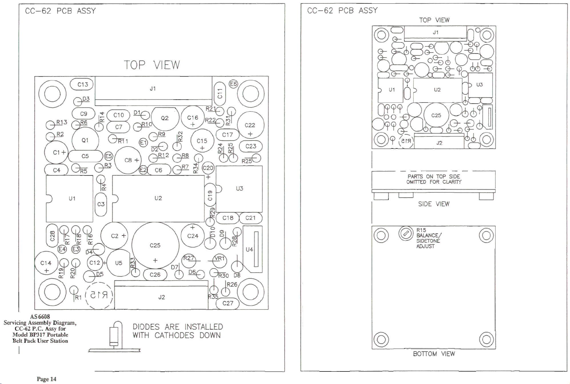
A
CC-62
PCB
ASSY
E-
CC-62
PCB
ASSY
TOP
VIEW
m
SIDE
VIM
CC-62
P.C.
~ssy
fa
wMklmli7Rrarblt
IkkPdrIkamim
DIODES
61
WITH
'
ARE
CATHODES
INSTALLED
DOWN
Page 15

 Loading...