

Page 1
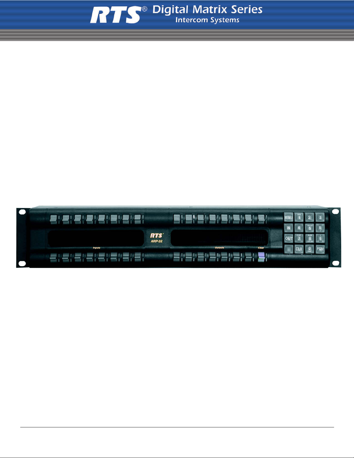
MODEL ARP-32
Audio Routing Panel
Upto and including Version 0.0.1
9350-7849-000 Rev A 5/2007
Page 2

PROPRIETARY NOTICE
SHIPPING TO THE MANUFACTURER
The product information and design disclosed herein were originated by
and are the property of Telex Communications, Inc. Telex reserv es all
patent, proprietary design, manufacturing, reproduction, use and sales
rights thereto, and to any article disclosed therein, except to the extent
rights are expressly granted to others.
COPYRIGHT NOTICE
Copyright 2007 by Telex Communications, Inc. All rights reserved.
Reproduction, in whole or in part, without prior written permission from
Telex is prohibited.
WARRANTY NOTICE
See the enclosed warranty card for further details.
CUSTOMER SUPPORT
Te chnical questions should be directed to:
Customer Service Department
RTS/Telex Communications, Inc.
12000 Portland Avenue South
Burnsville, MN 55337 USA
Telephone: 800-392-3497
Fax: 800-323-0498
Factory Service: 800-553-5992
RETURN SHIPPING INSTRUCTIONS
Customer Service Department
Telex Communications, Inc. (Lincoln, NE)
Telephone: 402-467-5321
Fax: 402-467-3279
Factory Service: 800-553-5992
Please include a note in the box which supplies the company name,
address, phone number, a person to contact regarding the repair , the type
and quantity of equipment, a description of the problem and the serial
number(s).
All shipments of product should be made via UPS Ground, prepaid (you
may request from Factory Service a different shipment method). Any
shipment upgrades will be paid by the customer. The equipment should
be shipped in the original packing carton. If the original carton is not
available, use any suitable container that is rigid and of adequate size. If
a substitute container is used, the equipment should be wrapped in paper
and surrounded with at least four (4) inches of excelsior or similar
shock-absorbing material. All shipments must be sent to the following
address and must include the Proof of Purchase for warranty repair.
Upon completion of any repair the equipment will be returned via
United Parcel Service or specified shipper, collect.
Factory Service Department
Telex Communications, Inc.
8601 East Cornhusker Hwy.
Lincoln, NE 68507 U.S.A.
Attn: Service
This package should include the following:
Part Number Description Qty
90107849-000
90107849-001
90107849-002
90107849-003
ARP-32, Lever Key (amber lens)
ARP-32, Pushbutton Key (amber lens)
ARP-32, Lever Key (purple and amber lens)
ARP-32, Pushbutton Key (purple amber lens)
1
532026-000 Power Supply 1
8800102668 Power Cord 1
93507849-000 ARP-32 User Manual 1
38110-387 Warranty Card 1
Page 3

Table
of
Contents
Introduction ...............................................................3
Features .....................................................................3
Specifications .............................................................5
Configuration and Operation ....................................7
Address Configuration ...............................................7
Setting Address ..........................................................7
Panel Options ............................................................7
Connections ...............................................................8
Key Configuration ......................................................8
Operation ...................................................................9
Assign Key Assignments .............................................9
Clear Key Assignments ..............................................9
Viewing Audio Paths ..................................................9
Changing Audio Paths .............................................10
Scrolling ...................................................................10
Clear the Scroll Window ..........................................10
Keypad Operation ....................................................11
AZedit and the ARP-32 ............................................11
Assign Key Assignments ...........................................11
Downloading Firmware to the ARP-32 ...................12
Menu Mode ..............................................................15
Display ..................................................................... 15
Item # .......................................................................15
Panel ID ...................................................................15
Setup Pages ..............................................................15
Version ..................................................................... 15
Service ......................................................................16
Baud Rate .................................................................16
Display Dim .............................................................16
Mod Assign ..............................................................16
Reset Cfg ..................................................................16
Save Cfg ...................................................................16
Test Panel ................................................................16
Notes ........................................................................17
Page 4

Page 5

CHAPTER 1
Intr oduction
Introduction
This manual describes the installation, programming, and operating procedures for the RTS Model ARP-32 Audio Routing
Panel. The ARP-32 provides the user with the ability to assign one of up to 16 crosspoints and/or up to 16 different
crosspoints. Through the use of up to three (3) expansion panels, allowing for a total of 64 input keys and 63 output keys, in
addition to the scroll key.
The sum total of ARPs and LCP-102s cannot exceed 15 in a system. The ARP-32 works with ADAM intercom matrix system.
The ARP-32’s key assignments and setup page assignments are stored by the ADAM MCII-e controller, and downloaded to
the panel when it powers up. Changes made at the ARP-32 are automatically saved by the MCII-e. Changes can also be made
using AZedit. ARP firmware ver sion 0.0.1 and later allows configuration of crosspoint connections.
Features
• Firmware Requirements
• ARP-32 version 0.0.1 or later
• ADAM MCII-e version 1.4.0 or later
• AZedit version 3.2 or later
• Single key activation to display audio paths that are forced to or from a particular port, as well as any crosspoint inhib its.
By pressing one input key and one output key, the user can toggle the force status of a single crosspoint.
• Uses AZedit’s Crosspoint screen as a graphical interface for the user to force and inhibit configured ports.
• The ARP-32 supports up to a maximum of three expansion panels, allowing a total of 64 input keys and 63 output keys, in
addition to a scroll key.
3
Page 6
Introduction
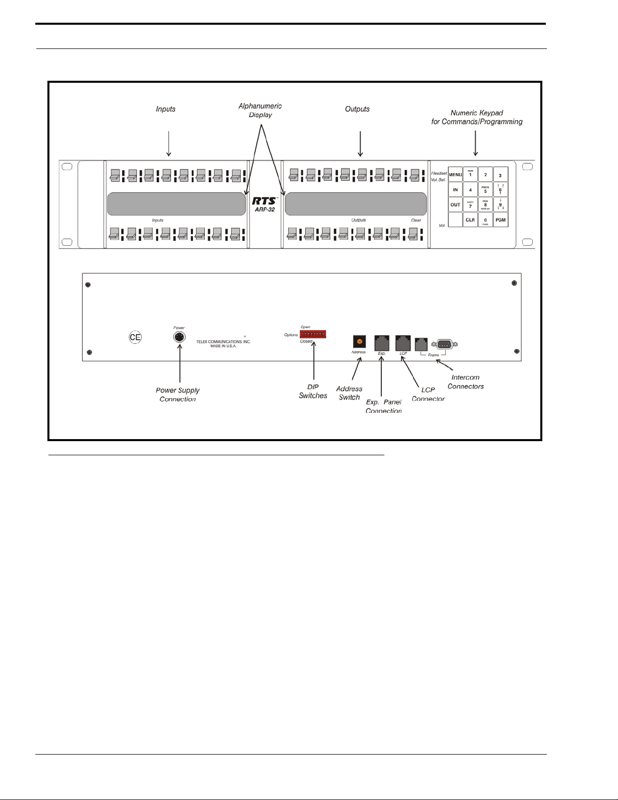
FIGURE 1. ARP-32 Reference View
4
Page 7

Specifications
Specifications
Matrix Connections
DE-9S Female
RJ12 Female
Power Requirements
100-240 VAC. 50/60 Hz, 1A
Environmental
Operating Temperature
0° C to 50° C
Storage Temperature
-20° C to 75° C
Humidity (Operating and Storage)
0%-95%, non-condensing
Dimensions
3.44” (88mm) high
19” (483mm) wide
3.5” (89mm) deep
Weight
5.5lbs (2.5kg)
Finish
Thermoplastic front panel, aluminum case and rear panel, light gray finish
Specifications subject to change without notice.
5
Page 8

Introduction
6
Page 9

CHAPTER 2
Configuration and Operation
Address Configuration
Address and Dip Switch Configuration is accomplished via the 16-position rotary switch (Address) and the 8-position DIP
switch, both located on the rear of the ARP-32. See Figure 1 on page 4 for the location of both switches.
Setting Address
A16-position rotary switch is used to select the polling ID. Valid IDs are 1-15. (Note, letters A through F on the rotary switch
represent IDs 10 through 15.) There can be at most one ARP-32 or LCP-102 at any given ID. Use a small flat blade screw
driver to rotate the switch to the desired setting.
Panel Options
The 8-position DIP switch is used to set options as follows
POSITION DEFINITION
8 Normally OPEN, when CLOSED forces boot down load mode.
7 Reserved for diagnostics, must be OPEN.
6 Unu sed , shou ld be left OPEN
5 Unu sed , shou ld be left OPEN
4 Disable keypad access, OPEN
3 When CLOSED disables screen saver
2 Unu sed , shou ld be left OPEN
1 Unu sed , shou ld be left OPEN
7
Page 10
Configuration and Operation
Connections
The ARP-32 connects to the UIO-256/PAP port, J3 on an ADAM system. The baud rate, as with all UIO-256, PAP, and LCP102 devices, can be either 9600 baud or 76.8 K baud.
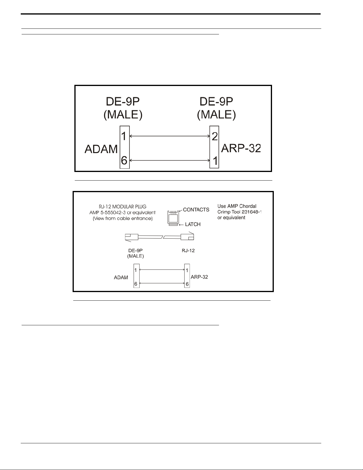
A cable must be made to connect the ARP-32 to the system.
FIGURE 2. ARP-32 D-Sub Cable Diagram
FIGURE 3. ARP-32 RJ12 Cable Diagram
Key Configuration
The ARP-32’s key assignments and setup page assignments are stored by the ADAM MCII-e controller, and downloaded to
the panel when it powers up. Changes made at the ARP-32 are automatically saved by the MCII-e. Changes can also be made
using AZedit.
8
Page 11

Operation
Operation
The ARP-32 Audio Routing Panel is used to establish audio paths by forcing crosspoints. The ARP-32 connects to J3 of the
XCP-ADAM-MC breakout panel, along with other PAPs, LCP-102s, and UIO-256 devices.
The ARP-32 hardware consists of 32 keys, physically separated into two groups (see Figure 1, “ARP-32 Reference View,” on
page 4). The keys on the left side of the ARP-32 panel are configured with input ports, whi le the keys on the right side of the
panel are configured with output ports. The optional expansion panel doubles the number of input and outpu t ports.
NOTE: If the intercom is configured to have separate input and output alphas, the input alphas are shown for the keys on
the left side of the panel and the output alphas are shown on the right.
Each button can have an assignment (a port number for an input port, and a port number for an output port). The ARP-32
displays the alphas for these assignments.
By pressing a single key, the user can view the audio paths forced between particular ports, as well as any crosspoint inhibits
that may be configured. By pressing an input key and an output key, you can toggle the force status of a single crosspoint.
The right-most output key on the lower row, the scroll key, is similar to a standard keypanel’s call waiting window. The
keypad can be used to scroll through a list of available ports and assign them to keys. You can also change the setup pages
assigned to the ARP-32 panel from the keypad.
Assign Key Assignments
To assign key assignments on the ARP-32, do the following:
1. Using the scroll up or scroll down keys, scroll to the port you want to assign to a key.
2. Press Copy (keypad number 7).
3. Press the key you want to assign the port.
Clear Key Assignments
To clear key assignments, do the following:
1. Verify the scroll window is clear.
2. Press Copy (keypad number 7).
This copies the blank assignment.
3. Press the key assignment you want to delete.
The blank assignment is assigned to the key.
Viewing Audio Paths
To view audio paths, do the following:
> On the front panel of the ARP-32, press any input key.
The outputs associated which the input is forced or inhibited are displayed.
• If the input is forced to at least one output, the key’s LED turns red. Otherwise, it turns green.
• For each output key, if the input is forced to that output, the output key’s LED turns red. If the input is inhibited
to that output, the output key’s LED flashes green.
• If there is a single output to which that input is forced, and which does not appear on any key assignment, then
the assignment is displayed in the scroll window.
• If there are multiple outputs to which the output is forced, which do not appear on any key assignments, then the
scroll window displays Many. The scroll-up (keypad number 6) and scroll down (keypad number 9) can be used
to scroll through the list of outputs. Once the input key is released, the scroll window is cleared.
9
Page 12

Configuration and Operation
NOTE: Similarly, pressing a single output key displays which inputs are forced or inhi bited to that ou tput.
Changing Audio Paths
To change an audio path, do the following:
1. Press and hold an input key .
2. Tap an output key assigned to a different port.
If the crosspoint is not already forced, the crosspoint becomes forced between to the two points.
NOTE: The scroll key can also be used to force and unforce crosspoints. However, it cannot be used to view the audio
paths. When using the scroll key to force/unforce, a crosspoint can be used as an input or an output key.
If a crosspoint (or its reciprocal) is inhibited, attempting to force or unforce the crosspoint has no effect. The ARP-32 cannot
change the crosspoint until the inhibit status is changed via AZedit.
A crosspoint cannot be forced or unforced if either the input or output port is a trunk port. If you try to force a crosspoint on a
trunked port, the port’s LED turns red briefly, and then will turn OFF again.
Scrolling
In normal scroll mode, the scroll up (keypad number 6) and the scroll down (keypad number 9) can be used to display a list of
available ports. The only ports displayed are those for which the LCP-102 is scroll enabled via AZedit.
To normal scroll using the ARP-32, do the following:
1. Using the scroll up (keypad number 6) or scroll down (keypad number 9) key, scroll to the port you want to assign to
a key .
2. Press Copy (keypad number 7).
3. Press the key you want to assign the port.
Prefix Scroll
Prefix scrolling allows you to scroll through the matrix ports in multiples of 100. This allows you to quickly get to higher ports
you want to use.
To prefix scroll using the ARP-32, do the following:
1. Press the Prefix key (keypad number 5).
Prefix Scroll mode is enabled.
2. Using the , scroll to the closest multiple of 100 to the desired port you want (for example, you want port
98, prefix scroll to 100).
3. Press PGM.
The scroll keys revert to individual ports.
4. Using the , scroll to the individual port you want.
Clear the Scroll Window
To clear the scroll window, do the following:
> Tap the scroll key up.
The scroll window clears.
10
Page 13

Keypad Operation
Keypad Operation
In addition to the scrolling operations the following key sequences can be performed.
SEQUENCE DESCRIPTION
NUM-#-#-#-PGM-key
COPY-key Copy the scroll key’s assignment to the specified key.
FUNC-COPY-key1-key2 Copy the first key’s assignment to the second key.
PAGE-#-PGM-key
FUNC-DISP-1 Display the panel’s polling ID on the scroll key.
FUNC-DISP-0
Program the specified key with the specified port number. The port number can be
1, 2, or 3 digits.
Change the setup page assigned to a group of 16 keys. For each physical panel
(main or expansion), one setup page is assigned to the input keys, and one setup
page is assigned to the output keys. (The input setup pages are independent of the
output setup pages.) The intercom supports a total of 8 input pages and 8 output
pages.
Enter test mode. This can be used to verify key, LED, and keypad operation.
Press CLR to exit test mode.
AZedit and the ARP-32
You can also use AZedit to configure the key assignments on the ARP-32.
Assign Key Assignments
To assign key assignments on the ARP-32 using AZedit, do the following:
1. From the System Menu, select ARP-32 Assignments.
The ARP-32s page appears.
2. From the ARP-32 port drop down menu, select the port you want to assign key assignments.
You can also us the ARP-32 port alpha drop-down menu to select the port.
NOTE: You can only assign point-to-point assignments.
3. There are 3 three ways to assign ports to the ARP-32 (in either the input or output assignments):
• Manually enter the port number (N001, N002, etc.) or port alpha.
• Right-click and use Change Assignment.
• Use the Assignment Grid.
11
Page 14
Configuration and Operation
Downloading Firmware to the ARP-32
NOTE: The ARP-32 firmware cannot be downloaded when the panel is operating as an ARP panel.
To download firmware to an ARP-32, do the following:
1. Power OFF the panel.
2. Disconnect the panel from the intercom.
3. Connect the panel to a spare keypanel port.
4. Change the polling ID to match the keypanel port (if connected to an AIO-16 in individual driver mode, it is
sufficient to verify the polling ID is in the 1-8 range).
5. Set DIP Switch 8 to CLOSED.
6. Power ON the panel.
The panel enters boot downloader mode and displays “This panel needs a firmware download!” in the lower left
window.
7. Open AZedit.
8. From the Status menu, select Software Versions.
The Software Versions submenu appears.
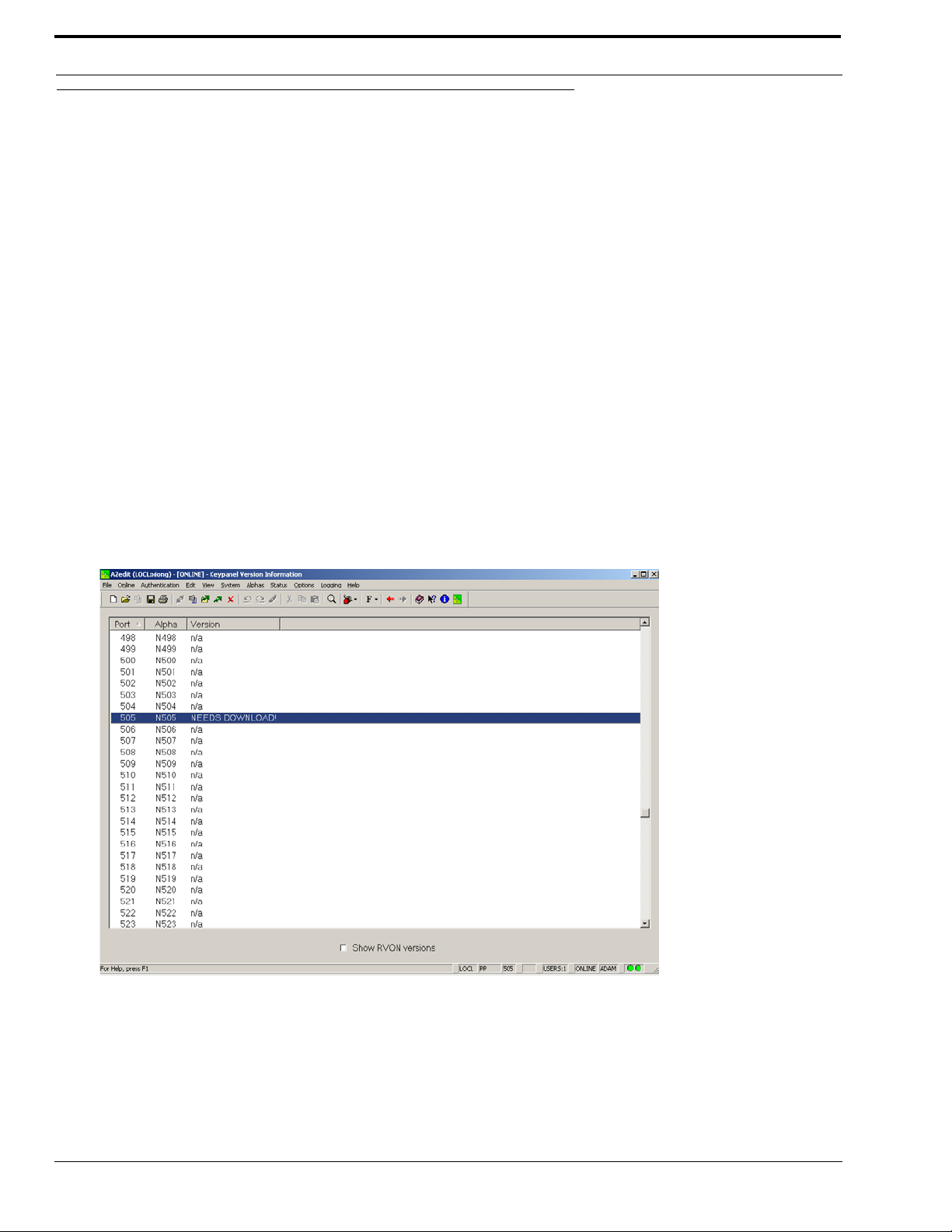
9. From the Software Versions submenu, select Keypanels.
The Keypanel Version Information screen appears. In the Version field, NEEDS DOWNLOAD will display for the
ARP-32.
10. Right-click the port to which the ARP-32 is connected.
A popup menu appears.
11. From the popup menu, select Download Firmware.
The Firmware Download window appears.
12. Using the browse feature, browse to the file to be downloaded (for example, ARP32.hex).
12
Page 15

Downloading Firmware to the ARP-32
13. Click Open.
The Download Device Firmware window appears.
14. Click Begin Download.
The download begins. Once the download is complete, a success message appears.
13
Page 16

Configuration and Operation
15. Click OK.
The ARP-32 firmware download is complete. This may take a few minutes to occur.
16. Verify the version upgrade in the Keypanel Version Information window is correct.
17. Power OFF the panel.
18. Set DIP Switch 8 to OPEN.
19. Change the polling ID back to the proper ARP-32 ID.
20. Disconnect the panel from the spare keypanel port.
21. Reconnect the panel to the PAP/LCP/UIO port.
22. Repower the panel.
14
Page 17

CHAPTER 3
Menu Mode
The MENU key provides access to two sub-menus which display various functions, the Display menu and the Service menu.
Display
To access the Display menu via the front panel, do the following:
1. On the ARP-32 keypad, press MENU.
Menu mode opens and Display appears.
2. Press PGM.
Item # appears in the right most display.
3. Use to scroll the Display menu options (described below).
Item #
The Item # menu item changes the display so item number are shown instead of alphas. The display reverts to the standard
alphas after 15 seconds, or when the CLR key is pressed.
Panel ID
The Panel ID menu item displays the polling ID of the ARP-32 (in the range 1 through 15).
Setup Pages
Use the Setup Pages menu item to display different configuration pages. For example, to display expansion panel 2 input
configuration, select X2/Inp.
Menu options include: Mn/Inp:1, Mn/Outp:1, X1/Inp, X1/Outp, X2/ Inp , X2/Outp, X3/Inp, X3/Outp.
Version
The Version menu item displays the version currently running on the ARP-32.
15
Page 18

Menu Mode
Service
To access the Service menu via the front panel, do the following:
1. On the ARP-32 keypad, press MENU.
Menu mode opens and Display appears.
2. Using the keypad, press either to scroll to Service.
3. Press PGM.
Baud appears in the right most display.
4. Use to scroll the Service menu options (described below).
Baud Rate
Use the Baud Rate menu item to set the baud rate at which audio is transmitted.
Menu options include: auto-baud, 9600 baud, 76.8K bd.
Display Dim
Use the Display Dim menu item to set the brightness of the fluorescent display. This menu item also allows you to activate the
screen saver (Scr Saver).
Menu options include: Dsp Off, Dim, Normal, Bright, Maximum, and Scr Saver.
Mod Assign
Use the Mod Assign menu item to configure module assignments for expansion panels.
Reset Cfg
Use the Reset Cfg menu item to restore panel to default setup.
Save Cfg
Use the Save Cfg menu item to save page setup and module assignments. Save Cfg saves page and module setup locally on
the ARP-32.
Test Panel
Use the Test Panel to put the panel in test mode. Test mode allows you to test the operation of the keys, LEDs, keypad, and
fluorescent
16
Page 19

Notes
Notes
17
Page 20

 Loading...