

Page 1
TECHNICAL BULLETIN
RTS-TB-030 25-July-2014
AIO-16 Audio Port Noise Susceptibility
Issue Severity: Product(s) Affected:
High: URGENT – Immediate Action
Required
Medium: Bosch Security Systems,
Inc. strongly recommends you take
the action(s) described below.
Low: Advisory
Notification Applies To:
Technical Support (TSS)
Repair (ASA)
Sales (NSO / RSO)
AIO-16s with manufacturing date codes
between June 2011 and August 2013 (approx.
1700 total cards)
Access Restrictions:
Internal Distribution ONLY
No Restrictions (Internal & External Distribution)
1.0 Issue
It was recently discovered that a portion of manufacturing test was omitted on AIO-16s made at the Bosch
Zhuhai manufacturing facility during the time period from June 2011 through August 2013. A series of
calibration steps related to Common Mode Noise Rejection (CMRR) optimization were omitted from the
manufacturing process. The result is that cards manufactured during this period have unbalanced audio
inputs that can be more susceptible to noise on the incoming audio lines. This allows noise to pass through
the input receiver stages of the AIO-16 and be heard by customers. In low noise environments, this may not
be detectable. However, any installation with noise present on the incoming audio (due to equipment
grounding issues, for example) may detect audible noise on these channels.
In general, since none of the 16 channels on the AIO-16 were properly calibrated by manufacturing, any
audio input may be vulnerable to this condition.
2.0 Resolution / Corrective Actions
In order to address this issue, the common mode rejection must be manually tuned on each of the 16 input
channels of the AIO-16. This is done by adjusting a potentiometer on each input audio amplifier circuit.
Bosch recommends that this adjustment be performed by an authorized service technician.
Page 2

3.0 Detailed Rework Instructions
NOTICE! The following rework should only be performed by qualified repair personnel
operating according to proper safety, ESD and soldering practices
____________________________________________________________________________
Necessary rework equipment (no electrical parts are necessary):
Small flat blade or jeweler's screwdriver
Magnifying glass (if required for improved visibility)
Digital Multimeter / Ohm-meter
The odd channels on the AIO-16 (1, 3, 5, 7, 9, 11, 13 and 15) follow the same layout topology around the opamps on the PCBA. The even channels on the AIO-16 (2, 4, 6, 8, 10, 12, 14 and 16) follow the same layout
topology around the op-amps on the PCBA. For this reason, a detailed description is given for the calibration
of the potentiometers associated with channels 1 and 2. This same methodology can then be repeated for
the remaining odd and even channels.
3.1 Rework for Channel 1
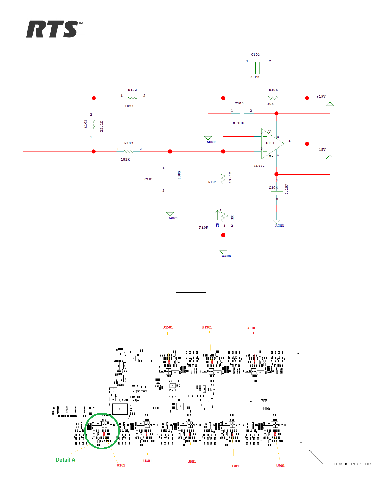
In the schematic below, locate potentiometer R105, 19.6 kOhm resistor R104 and 20 kOhm resistor R106.
During the manufacturing process, the potentiometers (R105 in this example) were not properly calibrated.
To achieve optimal common mode rejection of noise, the potentiometer R105 must be adjusted so that the
sum of R104 + R105 = R106 within 40 Ohms.
Bosch Security Systems, Inc., 2014
12000 Portland Ave S., Burnsville, MN USA
ww.rtsintercoms.com
RTS-TB-030
echnical Bulletin
5-June-2014
age 2 of 7
Page 3
TECHNICAL BULLETIN
FIGURE 1: The following assembly print shows a BOTTOM
of all eight dual op-amps in the AIO-16 design. Detail A circled in green shows the op-amp U101 associated
with the first two channels 1 and 2.
view of the AIO-16 Front Card and the location
Page 4

FIGURE 2: The following drawing shows DETAIL A from the assembly drawing which is a close-up of the
circuitry surrounding U101 for channels 1 and 2.
FIGURE 3: DETAIL B showing package detail of the op-amp:
Bosch Security Systems, Inc., 2014
12000 Portland Ave S., Burnsville, MN USA
ww.rtsintercoms.com
RTS-TB-030
echnical Bulletin
5-June-2014
age 4 of 7
Page 5

TECHNICAL BULLETIN
FIGURE 4: This final mark-up of the assembly print represents the TOPSIDE view of the AIO-16 Front Card
and shows the locations of ALL the potentiometers which need to be adjusted on the AIO-16 card.
Page 6

Channel 1 adjustment procedure:
NOTICE: The procedures described in the following sections require recording &
comparison of measurements. It may be desirable to keep a table or spreadsheet of
recorded resistance values to track completion.
____________________________________________________________________________
1. Use the op amp locations shown in FIgure 1 to locate U101.
2. Figure 2 is a magnification of the area around U101. The circle on U101 in Figure 2 represents the
corner corresponding to pin 1.
3. Figure 3 depicts the package pin out for U101.
4. Measure and record the resistance between U101 pin 1 and pin 2. This is the resistance of R106 and
should be between 19.00k and 21.00k ohms.
5. Locate R104 on the bottom assembly print Figure 2. It is just below U101.
6. Measure and record the resistance of R104.
7. Subtract the recorded value of R104 from the value of R106. This is the resistance that potentiometer
R105 must be adjusted to match.
8. Locate R105 on the AIO-16 using Figure 4.
9. Measure the resistance between pin 1 and pin 3 on R105. Use a screwdriver to adjust R105 to the
resistance calculated in step 7.
10. Recheck the resistance between U101 pin 1 and pin 2.
11. Check and record the resistance from U101 pin 3 and any of the AGND posts.
12. The difference between the resistance recorded in step 10 and step 11 above should be within 40
Ohms. Repeat 9 to 12 until the difference is within working parameters.
3.2 Rework for Channel 2
1. Measure and record the resistance between U101 pin 6 and pin 7. This is the resistance of R206 and
should be between 19.00k and 21.00k ohms.
2. Locate R204 on the bottom assembly print Figure 2. It is just below and tot he right of U101.
3. Measure and record the resistance of R204.
4. Subtract the recorded value of R204 from the value of R206. This is the resistance that potentiometer
R205 must be adjusted to match.
5. Locate R205 on the AIO-16 using Figure 4 (it is next to R105).
6. Measure the resistance between pin 1 and pin 3 on R205. Use a screwdriver to adjust R205 to the
resistance calculated in step 4.
7. Recheck the resistance between U101 pin 6 and pin 7.
8. Check and record the resistance from U101 pin 5 and any of the AGND posts.
9. The difference between the resistance recorded in step 7 and step 8 should be within 40 Ohms.
Repeat 6 to 9 until the difference is within working parameters.
Bosch Security Systems, Inc., 2014
12000 Portland Ave S., Burnsville, MN USA
ww.rtsintercoms.com
RTS-TB-030
echnical Bulletin
5-June-2014
age 6 of 7
Page 7

TECHNICAL BULLETIN
3.3 Rework for Channels 3 – 16
Channel 3 and channel 4 adjustment:
Repeat Sections 3.1 and 3.2 for channel 1 and channel 2 above but replace any reference to U101 with
U301. Replace any reference to R106 with R306. Replace any reference to R206 with R406. Replace any
reference to R105 with R305. Replace any reference to R205 with R405.
Channel 5 and channel 6 adjustment:
Repeat Sections 3.1 and 3.2 for channel 1 and channel 2 above but replace any reference to U101 with
U501. Replace any reference to R106 with R506. Replace any reference to R206 with R606. Replace any
reference to R105 with R505. Replace any reference to R205 with R605.
Channel 7 and channel 8 adjustment:
Repeat Sections 3.1 and 3.2 for channel 1 and channel 2 above but replace any reference to U101 with
U701. Replace any reference to R106 with R706. Replace any reference to R206 with R806. Replace any
reference to R105 with R705. Replace any reference to R205 with R805.
Channel 9 and channel 10 adjustment:
Repeat Sections 3.1 and 3.2 for channel 1 and channel 2 above but replace any reference to U101 with
U901. Replace any reference to R106 with R906. Replace any reference to R206 with R1006. Replace any
reference to R105 with R905. Replace any reference to R205 with R1005.
Channel 11 and channel 12 adjustment:
Repeat Sections 3.1 and 3.2 for channel 1 and channel 2 above but replace any reference to U101 with
U1101. Replace any reference to R106 with R1106. Replace any reference to R206 with R1206. Replace
any reference to R105 with R1105. Replace any reference to R205 with R1205.
Channel 13 and channel 14 adjustment:
Repeat Sections 3.1 and 3.2 for channel 1 and channel 2 above but replace any reference to U101 with
U1301. Replace any reference to R106 with R1306. Replace any reference to R206 with R1406. Replace
any reference to R105 with R1305. Replace any reference to R205 with R1405.
Channel 15 and channel 16 adjustment:
Repeat Sections 3.1 and 3.2 for channel 1 and channel 2 above but replace any reference to U101 with
U1501. Replace any reference to R106 with R1506. Replace any reference to R206 with R1606. Replace
any reference to R105 with R1505. Replace any reference to R205 with R1605.
 Loading...