

Page 1
ADAM - M
Advanced Digital Audio Matrix
System Installation Guide
F.01U.216.986
Rev. 10
OCTOBER/2015
Page 2
2 ADAM-M System Installation Guide
PROPRIETARY NOTICE
The product information and design disclosed herein were originated by and are the property of Bosch Security Systems, Inc.
Bosch reserves all patent, proprietary design, manufacturing, reproduction, use and sales rights thereto,
therein, except to the extent rights are expressly granted to others.
and to any article disclosed
COPYRIGHT NOTICE
Copyright 2012 by Bosch Security Systems, Inc. All rights
reserved. Reproduction, in whole or in part, without prior written
permission from Bosch is prohibited.
*All other trademarks are property of their respective owner
s.
WARRANTY AND SERVICE INFORMATION
For warranty and service information, refer to the appropriate web
site below:
RTS ............................................... www.rtsintercoms.com/warranty
RTSTW ..................................................... www.rtstw.com/warranty
AudioCom................................. www.telexaudiocom.com/warranty
RadioCom .................................. www.telexradiocom.com/warranty
Headsets ................................ www.intercomheadsets.com/warranty
CUSTOMER SUPPORT
Technical questions should be directed to:
Customer Service Department
Bosch Security Systems, Inc.
12000 Portland Avenue South
Burnsville, MN 55337 USA
Telephone: 877-863-4169
Fax: 800-323-0498
Info@rtsintercoms.com
THE LIGHTNING
FLASH AND
ARROWHEAD
WITHIN THE
TRIANGLE IS A
WARNING SIGN
ALERTING YOU OF
“DANGEROUS
VOLTAGE” INSIDE
THE PRODUCT.
SEE MARKING ON BOTTOM/BACK OF PRODUCT.
WARNING: APP
SPLASHING AND NO OBJECTS FILLED WITH LIQUIDS, SUCH AS VASES,
SHALL BE PLACED ON THE APPARATUS.
WARNING: THE M
CAUTION: T
THE CENTER PIN OF THIS PLUG MUST BE MAINTAINED.
WARNING: T
EXPOSE THIS APPRATUS TO RAIN OR MOISTURE.
WARNING:
ATTACHED TO THE FLOOR/WALL/RACK IN ACCORDANCE WITH THE
INSTALLATION INSTRUCTIONS.
O REDUCE THE RISK OF ELECTRIC SHOCK, GROUNDING OF
O REDUCE THE RISK OF FIRE OR ELECTRIC SHOCK, DO NOT
TO PREVENT INJURY, THIS APPARATUS MUST BE SECURELY
CAUTION: TO REDUCE
THE RISK OF ELECTRIC
SHOCK, DO
COVER. NO USERSERVICABLE PARTS
INSIDE. REFER
SERVICING TO
QUALIFIED SERVICE
PERSONNEL.
ARATUS SHALL NOT BE EXPOSED TO DRIPPING OR
AIN POWER PLUG MUST REMAIN READILY OPERABLE.
This product is AC only.
NOT REMOVE
THE EXCLAMATION
POINT WITHIN T
TRIANGLE IS A
WARNING SIGN
ALERTING YOU OF
IMPORTANT
INSTRUCTIONS
ACCOMPANYING
THE PRODUCT.
HE
TECHNICAL QUESTIONS EMEA
Bosch Security Systems Technical Support EMEA
http://www.rtsintercoms.com/contact_main.php
DISCLAIMER
The manufacturer of the equipment described herein makes
no expressed or implied warranty with respect to anything
contained in this manual and shall not be held liable for any
implied warranties of fitness for a particular application or
for any indirect, special, or consequential damages. The
information contained herein is subject to change without
prior notice and shall not be construed as an expressed or
implied commitment on the part of the manufacturer.
Bosch Security Systems, Inc.
System Installation Guide
F.01U.216.986
Rev. 10
Page 3

ADAM-M System Installation Guide 3
Important Safety Instructions
1. Read these instructions.
2. Keep these instructions.
3. Heed all warnings.
4. Follow all instructions.
5. Do not use this apparat
us near water.
6. Clean only with dry cloth.
7. Do not block any ventilation openings. Install in accordance with the
manufacturer
8. Do not install near any heat
’s instructions.
sources such as radiators, heat registers, stoves,
or other apparatus (including amplifiers) that produce heat.
9. Do not defeat the safety purpose of the polarized or grounding-type plug.
polarized plug has two blades with one wider than the other. A grounding
type plug has two blades and a third grounding prong. The wide blade or the
third prong are provided for your safety. If the provided plug does not fit
into your outlet, consult an electrician for replacement of the obsolete outlet.
10. Protect the power cord from being walked on or pinched parti
cularly at
plugs, convenience receptacles, and the point where they exit from the
apparatus.
11. Only use attachments/accessories speci
12. Use only with the cart, stand, tripod, bracket
fied by the manufacturer.
, or table specified by the
manufacturer, or sold with the apparatus. When a cart is used, use caution
when moving the cart/apparatus combination to avoid injury from tip-over.
A
13. Unplug this apparatus during lightning storms or when unused for long
periods of time.
14. Refer all servicing to qualified service personnel. Servicing is required
when the apparatus has been damaged in any way
cord or plug is damaged, liquid has been spilled or objects have fallen into
the apparatus, the apparatus has been exposed to rain or moisture, does not
operate normally, or has been dropped.
Bosch Security Systems, Inc.
System Installation Guide
, such as power-supply
F.01U.216.986
Rev. 10
Page 4

4 ADAM-M System Installation Guide
Bosch Security Systems, Inc.
System Installation Guide
F.01U.216.986
Rev. 10
Page 5

Table
of
Contents
INTRODUCTION ......................................................................................................................... 9
General Description .................................................................................................................................9
Features ....................................................................................................................................................9
Reference View ......................................................................................................................................10
Specifications .........................................................................................................................................11
Alarm Operation ....................................................................................................................................12
Status Relay Pin Out .......................................................................................................................................... 12
CHASSIS ..................................................................................................................................... 13
Mounting the Central Matrix Components ............................................................................................13
Initial Setup ............................................................................................................................................15
Checklist before cabling: ................................................................................................................................... 15
ADAM-M Cards ....................................................................................................................................17
Front Card Access ............................................................................................................................................. 17
Card Removal and Installation .......................................................................................................................... 17
Unused Back Card Slots .................................................................................................................................... 19
Supported ADAM-M Configurations ................................................................................................................ 19
Master Controller Card DIP Switches ............................................................................................................... 20
Power Supply Removal and Installation ................................................................................................23
Fan Removal and Replacement ..............................................................................................................24
AC Power - Chassis ...............................................................................................................................25
Fan Air Filter Replacement ....................................................................................................................25
Fuse Replacement ..................................................................................................................................26
ADAM-M Frame Power-Up ..................................................................................................................27
Circuit Card Reset and Fail Indication ...................................................................................................28
XCP-ADAM-MC ......................................................................................................................... 29
Breakout Panel .......................................................................................................................................29
Connector Pinouts ..................................................................................................................................30
Connections .................................................................................................................................................... 32
DEVICE CONNECTIONS ......................................................................................................... 35
General Information ...............................................................................................................................35
Logical Keypanel Numbers ...................................................................................................................36
General Procedure for Connecting Devices to the Intercom .................................................................37
Specifications .....................................................................................................................................................38
Baud Rates for the XCP-ADAM-MC ...............................................................................................................38
Bosch Security Systems, Inc.
System Installation Guide
F.01U.216.986
Rev. 10
Page 6

6 ADAM-M System Installation Guide
Connecting the Master Controller Breakout Panel ............................................................................................39
Configuration Computer Connection and Check .............................................................................................. 39
Trunk Master .....................................................................................................................................................40
General Description ....................................................................................................................................... 40
Hardware Requirements ................................................................................................................................. 40
Connecting the TM-2000/MTM-2000 ........................................................................................................... 41
UIO-256/GPIO-16 Input/Output Frame ............................................................................................................41
Connecting a single UIO-256/GPIO-16 Frame .............................................................................................. 42
Connecting Additional UIO-256/GPIO-16 Frames ....................................................................................... 42
PAP-32 .............................................................................................................................................................. 44
General Description ....................................................................................................................................... 44
Connecting a PAP-32 ..................................................................................................................................... 44
LCP-102 ............................................................................................................................................................ 45
General Description ....................................................................................................................................... 45
Connecting an LCP-102 ................................................................................................................................. 45
RJ-45 BACKCARD ..................................................................................................................... 57
Notes ......................................................................................................................................................61
Bosch Security Systems, Inc.
System Installation Guide
F.01U.216.986
Rev. 10
Page 7

List
of
Figures
FIGURE 1. ADAM-M Reference View ............................................................................................... 10
FIGURE 2. ADAM-M—Proper Carrying Position ............................................................................. 13
FIGURE 3. ADAM-M–Blank Card ..................................................................................................... 19
FIGURE 4. MCII-e Master Controller Card Board View. (Gilman, Mike, illus. 2010) ...................... 20
FIGURE 5. Reset Button and LED Failure Indicator .......................................................................... 28
FIGURE 6. XCP-ADAM-MC (Gilman, Mike, illus. 2010) ................................................................. 29
FIGURE 7. Typical GPI input connection ........................................................................................... 32
FIGURE 8. Typical GPI output connection ......................................................................................... 33
FIGURE 9. Y-Cable Diagram .............................................................................................................. 43
FIGURE 10. Interconnect Cable From ADAM-M ................................................................................ 46
FIGURE 11. Cable to interconnect two (2) LCPs. ................................................................................. 46
FIGURE 12. Keypanel with Data Cabling ............................................................................................. 47
FIGURE 13. Audio Only Cabling .......................................................................................................... 48
Bosch Security Systems, Inc.
System Installation Guide
F.01U.216.986
Rev. 10
Page 8

8 ADAM-M System Installation Guide
Bosch Security Systems, Inc.
System Installation Guide
F.01U.216.986
Rev. 10
Page 9

CHAPTER 1
Introduction
General Description
Re-engineered with the latest design and technology, the ADAM-M Matrix Intercom bridges legacy with innovation.
The sleek re-design provides 128+ ports in
master controllers and power supplies. The Matrix frame supports current ADAM cards, including AIO-16, RVON-16,
MADI-16 Plus, DBX, TriBus and MCII-e controllers. It also supports existing ADAM wiring schemes and options.
Built for the entire world and the REAL w
The chassis is built with improved low noise cooling, hot-swapp
status reporting.
an extremely compact 3 RU (rack unit) package, with full redundancy on the
orld, the chassis plugs and plays anywhere, running on 90-264VAC at 50/60Hz.
able components (including cooling modules), and improved
Features
Port Density The ADAM-M supports 128+ ports in a 3RU unit, giving more functionality with less rack
Redundant Master
Controllers
Power System The ADAM-M has two fully redundant, hot-swappable power supplies that work from 90-
Compatibility Bridging
wit
h Past and Future
Extended Back Card
Ca
pabilities
space used.
Every ADAM-M is equipped with two (2) master controllers th
other, so if one fails the other will take over until the failed controller can be brought back
online.
2
64VAC, 50/60Hz with low noise cooling and advanced status reporting capabilities. UL, CSA,
CE, VDE, FCC and PSE approved.
The ADAM-M supports existing legacy products, such as the AIO-16, RVON-16, MCII-e,
Tribus, DBX, and MADI, as well as our next generation of cards.
The ADAM-M includes provisions for expanded back cards to increase wiring options and
simplicity.
at are fully redundant to each
Integration/Expansion The ADAM-M, utilizing existing cables and bus expanders, integrates and expands existing
intercom systems
Hot Swappable
Co
mponents
Bosch Security Systems, Inc.
Not only are the I/O cards in the ADAM-M hot-swappable, but the power supplies and fans are
completely removable and hot swappable, making replacement and maintenance easier than
ever.
into larger systems with minimal effort.
System Installation Guide
F.01U.216.986
Rev. 10
Page 10
10 Introduction ADAM-M System Installation Guide
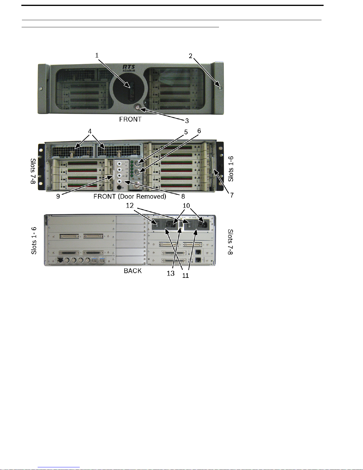
Reference View
FIGURE 1. ADAM-M Reference View
1. Status LEDs
2. Front Cover Thumb Screws
3. Alarm Override Button
4. Power Supplies
5. DC Power On/Off Button
6. DC Power On/Off Button
7. Filter Module
8. Power Test Point Banana Jacks
9. Fan Module
10. AC Power Connectors
11. Fuses
12. AC Power On/Off Button
13. Status Relay Connector
Bosch Security Systems, Inc.
System Installation Guide
F.01U.216.986
Rev. 10
Page 11

ADAM-M System Installation Guide Introduction 11
Specifications
General
Matrix Size
16-128 ports, frame expandable up to 880 ports
Cards Supported
AIO-16: 16 Analog ports with individual, bi-directional data 15Hz to 20kHz, >90dB A-weighted S/N
MADI-16 Plus:
RVON-16: 16
DBX: Dual Bus Expander for linking between ADAM-M and other ADAM frames.
Tri -B us: Triple Bus Expander for linking between ADAM-M and other ADAM frames.
MCII-e:
Electrical
Power Supply
Universal PSU 90V to 264V 50/60Hz
Power Consumption
System dissipation up to 237 Watts
16 to 64 channels of MADI
VoIP ports supporting G.711, G.729A, and G.723
Ethernet Master Controllers in redundant configuration.
Environmental
Temperature
Operating: 0°C to +50°C (+32°F to +122°F)
Storage: -40°C to +55°C (-40°F to +131°F)
Humidity: 0 to 95% non-condensing
Dimensions
Height: 5.25” (133.35mm) 3RU
Width (frame with rack ears): 19” (482.6mm)
Depth: 20
Weight: 2
” (508mm)
2.05lbs (10.00kg)
Approvals
UL, CSA, CE, VDE, FCC, PSE, REACH, RoHS, WEEE, CCC, ACMA C-Tick, China RoHS, and IECEE CB Scheme
CAUTION:
• Ventilation: Minimum 6” clearance on the sides to keep fan area unobstructed (EN 60065 Clause 4.1.4)
• Apparatus shall not be exposed to dripping or splashing and no objects filled with liquids shall not be placed on
the apparatus (EN 60065 Clause 5.4.1a).
• The ADAM-M is to be connected to a mains socket outlet with a protective earth connection (EN 60065 Clause
5.4.1d).
REFERENCE: For
information on ADAM-M Frame accessory specification, consult the individual device’s user manual.
Most user manuals can be found at www.rtsintercoms.com.
Bosch Security Systems, Inc.
System Installation Guide
F.01U.216.986
Rev. 10
Page 12

12 Introduction ADAM-M System Installation Guide
Alarm Operation
The ADAM-M is equipped with a power supply fault, fan fault, and over-temperature alarm. If there is a problem detected in
any of these areas, an audible alarm sounds.
Power issue If only one (1) powe
Fan issue If any of
Heat issue If the heat
the three (3) fans stops, an alarm is triggered.
within the chassis goes above 140°F (60°C), an alarm is triggered. There are three (3) heat
r supply is running, an alarm sounds because redundant power is not active.
sensors in the ADAM M chassis – at the chassis rear, on the backplane, and in the chassis air vent.
The chassis provides an aux alarm relay for when the chassis mounted
in unoccupied areas to trigger a remotely located alarm.
Contact closure is given to the connector when a failure is detected.
It is possible to disable these alarms by
switch is engaged, a red ring appears around the button, the al
engaging the Alarm Override button (see Figure 1 on page 10). If the alarm override
arm is being by-passed and no notification is heard. By
disengaging the alarm override button, the alarm resumes its audible notification.
NOTE:
• The power supply alarm also sounds if a power supply is turned off. This is normal. Either turn on the
power supply, or turn off the alarm override switch.
• Alarm override does not override the alarm for the status relay connection.
Status Relay Pin Out
Relay 1 consists of pins 1, 2, and 6 of the DB-9 Connector.
IMPORTANT: The relay driver must be capable of 5v, 50ma
TABLE 1. DB-9 Pin Out
Pin Description
1 NO
2 NC
3 n/a
4 n/a
6 Common
7 n/a
8 n/a
9 n/a
.
Bosch Security Systems, Inc.
System Installation Guide
F.01U.216.986
Rev. 10
Page 13

CHAPTER 2
Chassis
Mounting the Central Matrix Components
CAUTION: To avoid potentially dropping and damaging the ADAM-M, verify the thumbscrews are secure and be sure to
grasp the front door and the main unit rack ears together when transporting the frame.
FIGURE 2. ADAM-M—Proper Carrying Position
Bosch Security Systems, Inc.
System Installation Guide
F.01U.216.986
Rev. 10
Page 14
14 Chassis ADAM-M System Installation Guide
To mount the ADAM-M unit, do the following:
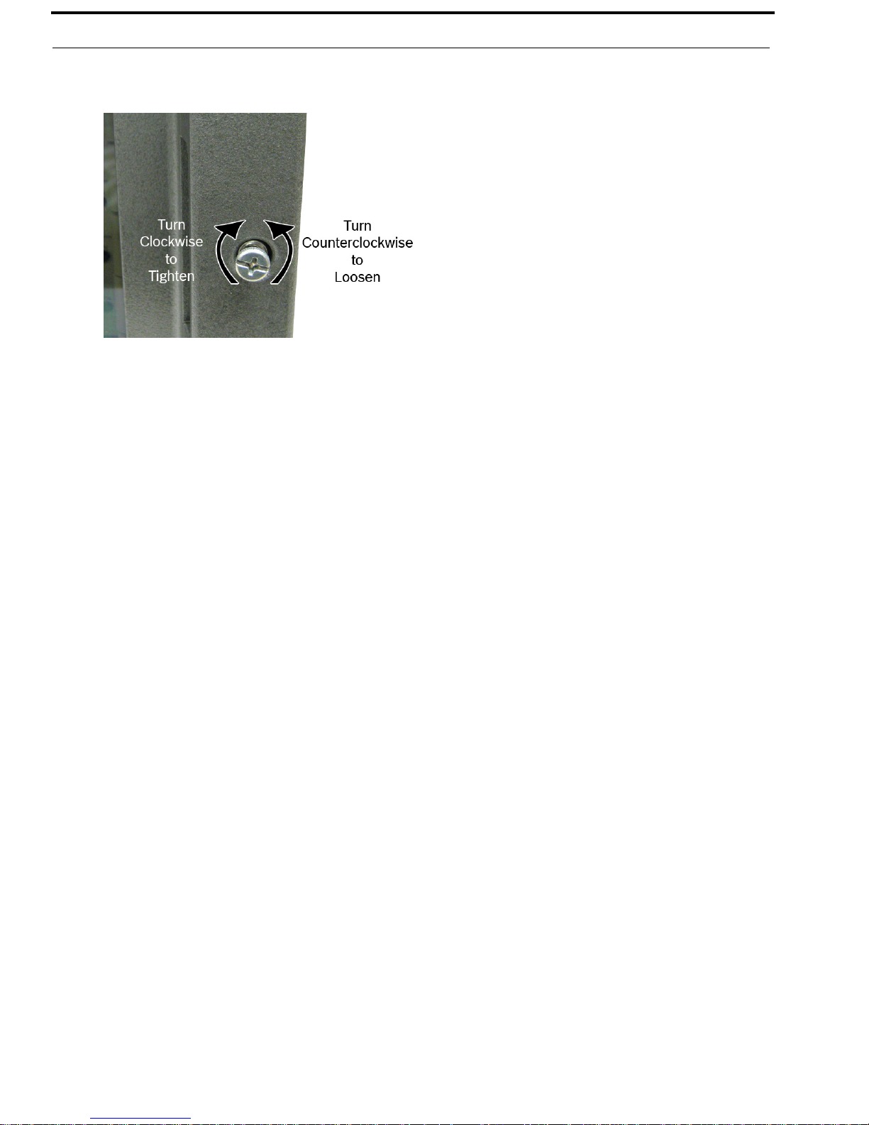
1. Using a flatblade screwdriver, loosen the thumb screws on both sides of the front door. (see Figure 1 on page 10)
2. Remove the front door from the ADAM-M.
3. Bolt the ADAM-M Frame into the front of the equipment rack.
4. Using the rear brackets, bolt the ADAM-M into the back of the equipment rack.
5. Replace the front cover on the ADAM-M.
NOTE: Make su
re the ventilation holes on the both sides are unobstructed (minimum 2”). The rack space behind the
ADAM-M Card Frame should be kept completely clear to allow for connections and the insertion and removal
of back cards (at least 2 feet).
Station Breakout Panels and Translation Panels are usually mounted
in the back of the equipment rack, and are generally
arranged to allow intercom station cabling to exit the frame at the top or bottom, as required.
Optional UIO-256/GPIO-16 Frames can be mounted in the front
UIO-256/GPIO-16, consideration should be given to the visibility of the fron
of an equipment rack. When positioning a
t panel LEDs, which provide visual indication for
any active inputs and outputs.
Optional PA
P (Program Assign Panels) units should be mounted in the front of an equipment rack. Generally, a PAP should be
located slightly below eye height when sitting or standing to allow for viewing of the front panel indicators and easy activation
of the front panel controls.
Bosch Security Systems, Inc.
System Installation Guide
F.01U.216.986
Rev. 10
Page 15
ADAM-M System Installation Guide Chassis 15
Initial Setup
IMPORTANT: If you are running four (4) cards (including master controllers) or less, verify the Load Card is installed.
Checklist before cabling:
•
Verify unit is not damaged
• Verify the power supplies are firmly seated in their slots
• Verify the MCII-e (s) are in slots MC1 and MC2
To set up the ADAM-M, do th
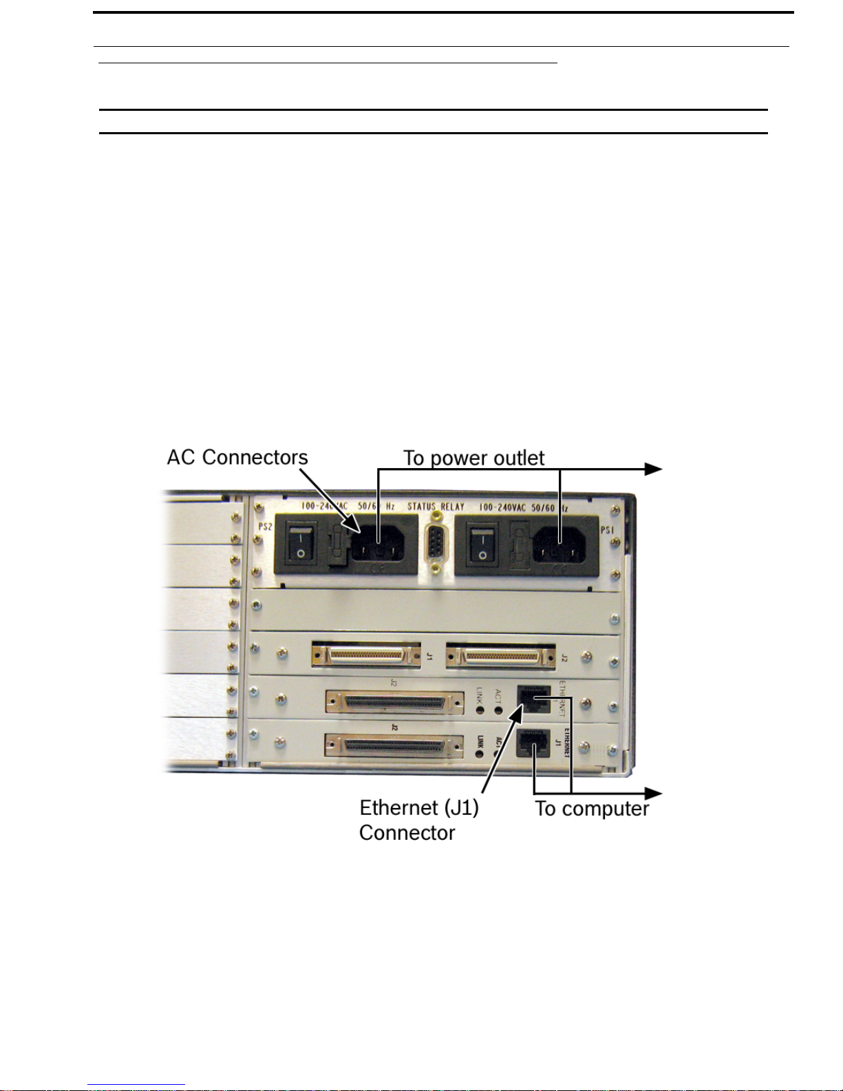
1. Connect the power cord connector end(s) to the power module on the rear side of the ADAM-M.
2. Connect the power cord plug(s) to an electrical outlet.
3. Using an Ethernet cable, connect the Primary MCII-e (J1) to the computer hosting AZedit.
4. Using an Ethernet cable, connect the Standby MCII-e (J1) to the computer hosting AZedit (optional).
5. Using the appropriate user manuals, cable the specific I/O cards used in your system.
REFERENCE: Fo
r a complete list of RTS User Manuals, visit http://www.rtsintercoms.com/manuals.php.
e following
6. Power on the ADAM-M unit.
Bosch Security Systems, Inc.
System Installation Guide
F.01U.216.986
Rev. 10
Page 16
16 Chassis ADAM-M System Installation Guide
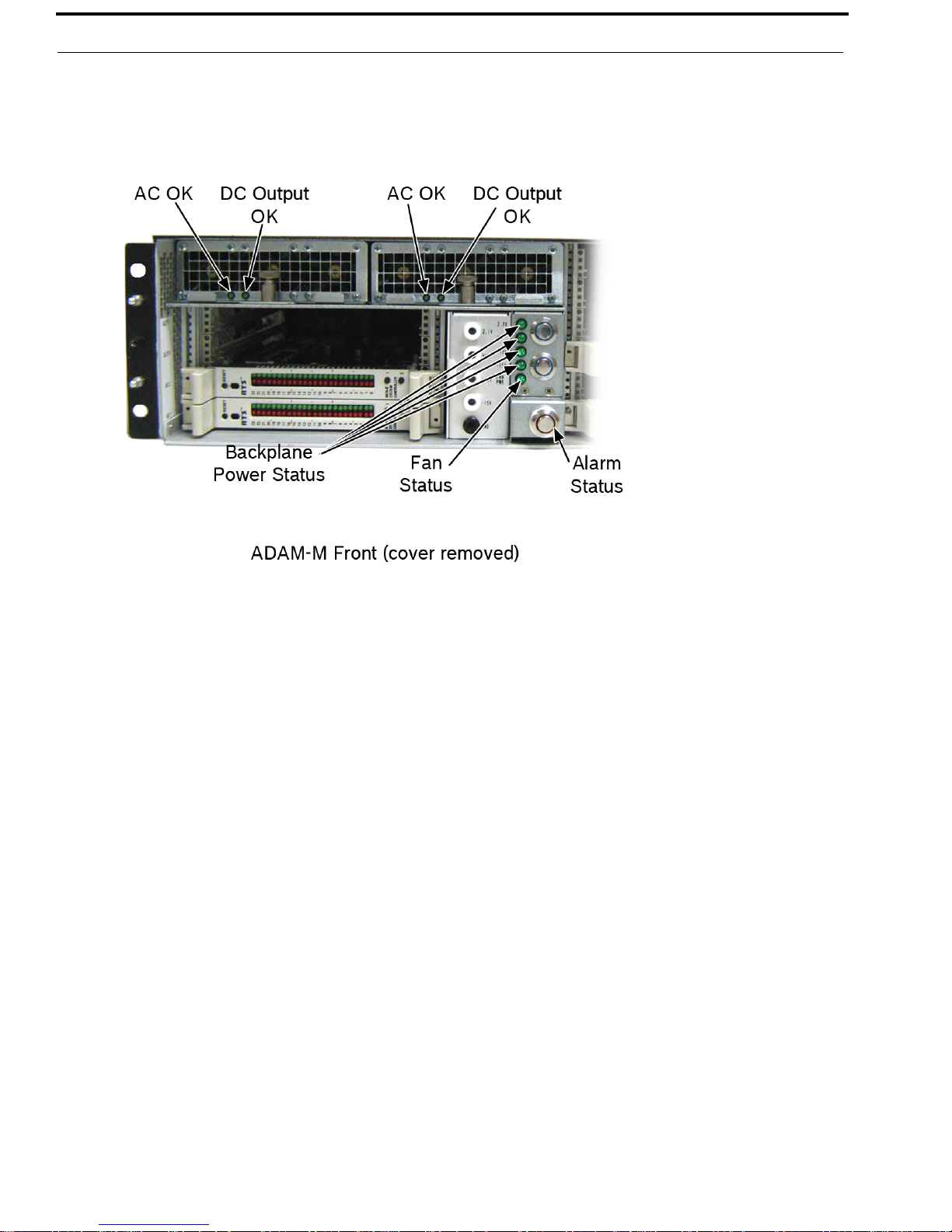
7. Verify the following Status LEDs are good (on):
• AC/DC Status
• Power Status
• Alarm Status
• Fan Status
8. Using AZedit, verify ADAM is communicating with the computer.
Bosch Security Systems, Inc.
System Installation Guide
F.01U.216.986
Rev. 10
Page 17
ADAM-M System Installation Guide Chassis 17
ADAM-M Cards
Front Card Access
To access the front cards, do the following
1. Loosen the thumb screws on both sides of the front door. (see Figure 1 on page 10)
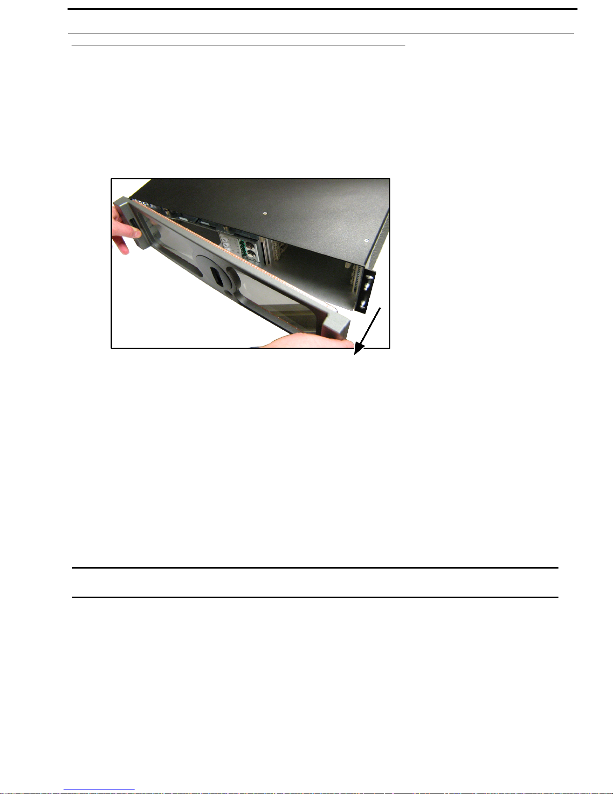
2. Grasp the ADAM-M front cover on each hand hold.
3. Firmly pull the chassis front door from one side.
The other side of the chassis door automatically pops free.
4. Remove the front door and set it aside.
Card Removal and Installation
All ADAM-M circuit cards can be hot-installed, which means you do not have to turn the power off before installing or
removing a card. This permits continuous operation of the intercom system - with no interruptions to unaffected ports - in the
event of a card failure.
NOTE:
• Tribus cards should be placed in slot 5 or slot 6.
• When using MADI cards, place the cards in slots 4 and 8 of the ADAM-M frame for maximum system
reliability.
• If less than four (4) cards are loaded in the ADAM-M (including Master Controllers), use the Load Card
in slot 1. This guarantees power supply redundancy.
CAUTION: The connector pins on the back plane inside the ADAM-M frame can be easily damaged by improper or hurried
insertion of the circuit cards.
Bosch Security Systems, Inc.
System Installation Guide
F.01U.216.986
Rev. 10
Page 18

18 Chassis ADAM-M System Installation Guide
To insert back cards, do the following:
1. Orient the card so the component side of the board is facing up.
2. Insert the card edges into the right and left guides in the back of the ADAM-M frame.
3. Push the card in until the mounting plate is flush with the ADAM-M frame.
4. Install mounting screws in the left and right of the card plate to lock it in place.
IMPORTANT: Slots designate MC1 and MC2 are reserved for Master Controllers. Do not install I/O cards in these
slots.
To insert front cards, do the following:
1. Orient the front card so the reset switch is on the left-hand side.
2. Insert the card edges into the right and left card guides in the front of the ADAM-M frame.
3. Push the front card into the slot until initial resistance is felt.
4. When initial resistance is felt, apply slightly more pressure to begin engaging the connector pins.
5. Once the connector pins have started to engage, press firmly to completely seat the connectors.
When the card is properly seated, the card mounting plate should be flush with the ADAM-M frame.
NOTE: Mount screws for the front cards are not required, but are recommended for mobile installations.
To remove a front card, do the following:
1. Press the ejector levers.
2. Once released from the back plane connector, pull the front card straight out of the frame.
To remove a back card, do the following:
1. Release the front card by pressing the ejector levers.
2. Unscrew and remove the back card mounting screws.
3. Remove the back card.
NOTE: When a front or back audio card is removed, the displays on any keypanel connected to that card displays
asterisks instead of the normal key assignments. After a card is reinstalled, it may take a minute or two for the
keypanel displays to return to normal.
Bosch Security Systems, Inc.
System Installation Guide
F.01U.216.986
Rev. 10
Page 19
ADAM-M System Installation Guide Chassis 19
Unused Back Card Slots
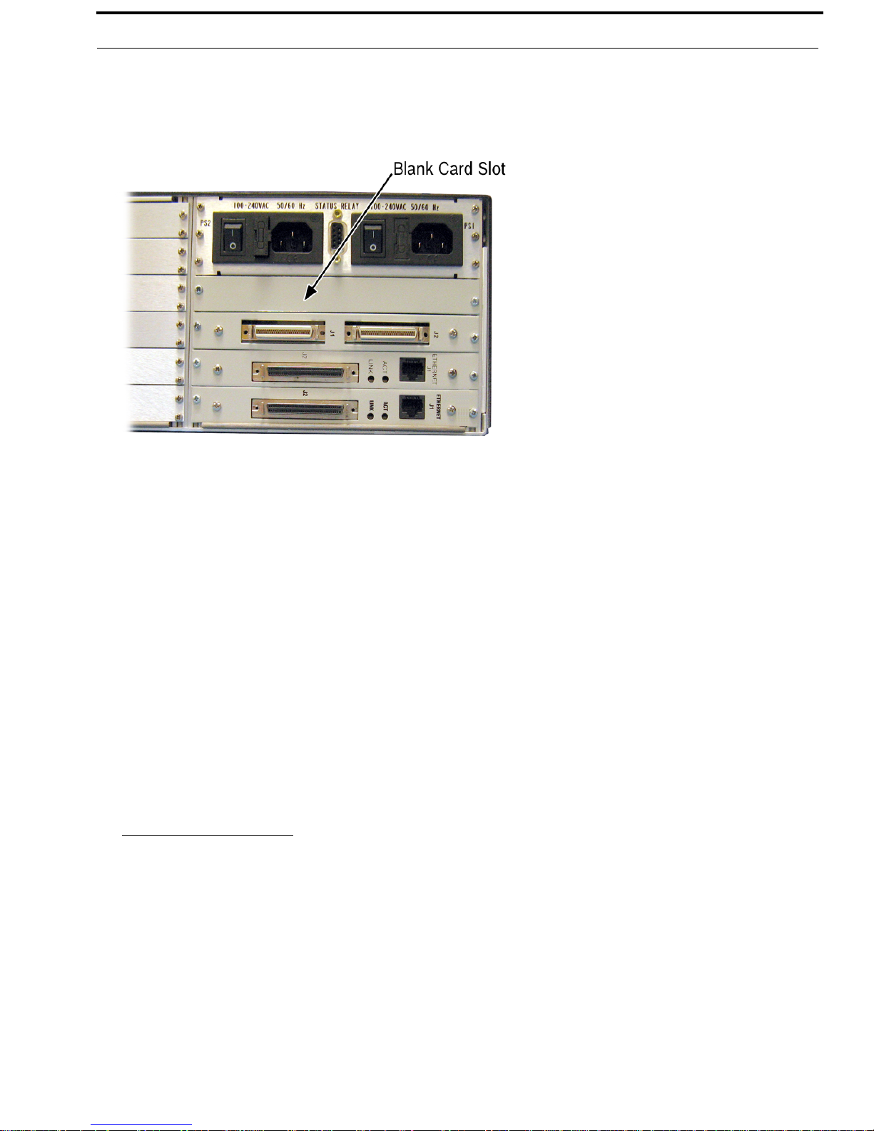
To ensure proper air flow, each unused back card slot should be fitted with a card blank, shown in Figure 3,
(P/N 9000-7467-003) to cover the opening.
FIGURE 3. ADAM-M–Blank Card
Supported ADAM-M Configurations
The ADAM-M has a limit of only two (2) MADI cards. The following configurations are supported:
TABL E 2 . Supported MADI/TBX Configurations for the ADAM-M
ADAM-M with 2 MADI cards and 0 TBX Cards
Place MADI Cards in slots 3 and 6
ADAM-M with 2 MADI cards and 1 TBX Card
Place MADI Cards in slots 3 and 8
Place TBX Card in slot 6
ADAM-M with 2 MADI cards and 2 TBX Cards
Place MADI Cards in slots 3 and 8
Place TBX Cards in slots 5 and 6
ADAM-M with 1 MADI Card
Place MADI Card in slot 8
Place TBX Cards in slots 4, 5, and 6
a. When three (3) TBX cards are used in the ADAM-M, only one (1) MADI card can be used in the system.
a
and 3 TBX Cards
Bosch Security Systems, Inc.
System Installation Guide
F.01U.216.986
Rev. 10
Page 20

20 Chassis ADAM-M System Installation Guide
Master Controller Card DIP Switches
As shipped from the factory, all master controller card DIP switches are set to the default operation position. These settings are
satisfactory for most applications. Optional settings are summarized in Table 3 on page 21 If any changes are made to the
settings, make sure both the main and backup controller cards are set the same.
FIGURE 4. MCII-e Master Controller Card Board View. (Gilman, Mike, illus. 2010)
Bosch Security Systems, Inc.
System Installation Guide
F.01U.216.986
Rev. 10
Page 21

ADAM-M System Installation Guide Chassis 21
TABL E 3 . MCII-e Version 1.6.2 Dip Switch Settings
Dip Switch Description
1 Debug Only! Must be in open position.
2 Sets the baud rate for the AZedit serial connection via J1. By default, AZedit is set for COM 1 and 38,400
k
bps (38.4K). The baud rate set in AZedit must match the baud rate setting of the Master Controllers in
ADAM.
DEFAULT = closed
OPEN =
CLOSED = 3
9600
8.4k Baud
3 Reserved, keep in open position.
4 Reserved, keep in open position.
5 Reserved, keep in open position.
6 Debug Only! Must be in open position
7 Reserved, keep in open position.
8 Debug Only! Must be in open position.
TABL E 4 . MCII-e Version 2.0.0 or Later Dip Switch Settings
Dip Switch Description
1 Debug Only! Must be in open position.
2 Sets the baud rate for the AZedit serial connection via J1. By default, AZedit is set for COM 1 and 38,400
k
bps (38.4K). The baud rate set in AZedit must match the baud rate setting of the Master Controllers in
ADAM.
DEFAULT = closed
OPEN =
CLOSED = 3
9600
8.4k Baud
3 Reserved, keep in open position.
4 Reserved, keep in open position.
5 Reserved, keep in open position.
6 Debug Only! Must be in open position
7 Reserved, keep in open position.
8 Debug Only! Must be in open position.
Bosch Security Systems, Inc.
System Installation Guide
F.01U.216.986
Rev. 10
Page 22

22 Chassis ADAM-M System Installation Guide
TABLE 5. MCII-e Version 1.19.2 Dip Switch Settings
Dip Switch Description
1 Debug Only! Must be in open position.
2 Sets the baud rate for the AZedit seri
al connection via J1. By default, AZedit is set for COM 1 and 38,400
kbps (38.4K). The baud rate set in AZedit must match the baud rate setting of the Master Controllers in
ADAM.
DEFAULT = c
OPEN = 960
CLOSED = 38.4k
losed
0
Baud
3 Reserved, keep in open position.
4 Reserved, keep in open position.
5 Reserved, keep in open position.
6 Debug Only! Must be in open position
7 Determines Master/Slave Frame in
DEFAULT = c
OPEN = Slave
CLOSED
= Master Frame
a multi-frame system.
losed
Frame
8 Debug Only! Must be in open position.
Bosch Security Systems, Inc.
System Installation Guide
F.01U.216.986
Rev. 10
Page 23

ADAM-M System Installation Guide Chassis 23
Power Supply Removal and Installation
To remove the power supply, do the following:
1. Remove the ADAM-M front door.
2. Lift up the finger lock holding the power supply in place.
3. Rotating counterclockwise, rotate the finger lock half a turn.
The finger lock stays in the open position.
4. Pull the power supply out of the ADAM-M chassis.
Bosch Security Systems, Inc.
System Installation Guide
F.01U.216.986
Rev. 10
Page 24

24 Chassis ADAM-M System Installation Guide
Fan Removal and Replacement
To remove the fan unit, do the following:
1. Remove the front door from the ADAM-M unit.
2. Lift up the thumbscrew for power supply 2.
3. Find the Fan Removal Tab.
4. Using the fan removal tab, pull the fan unit from the ADAM-M chassis.
Bosch Security Systems, Inc.
System Installation Guide
F.01U.216.986
Rev. 10
Page 25

ADAM-M System Installation Guide Chassis 25
AC Power - Chassis
The ADAM-M Chassis has two (2) separate power sources; the power to the chassis and the power to the power supply. The
power on/off buttons on the front of the unit power the chassis, while the AC power connectors on the rear of the unit power
the power supply. See Figure 1 on page 10. Pressing the power on/off buttons on the front of the unit will not fully power down
the ADAM-M. You must press the AC power connector
switches on the rear of the unit to turn off the power supplies.
To power on the
1. On the back of the ADAM-M, press both AC power switches to the on position.
2. On the front of the ADAM-M unit, press the power supply on/off button located. See Figure 1 on page 10.
NOTE: Co
ADAM-M, do the following:
nnecting both AC inputs assures continued operations of the ADAM-M Frame in the event that one (1)
power supply fails. If desired, two (2) separate AC power phases may be connected. This protects not only
against a power supply failure, but also against a loss of power to one phase.
Fan Air Filter Replacement
To replace fan air filter, do the following:
1. Using a flat blade screwdriver, loosen the thumb screws on both sides of the front door. (see Figure 1 on page 10)
2. Remove the front door from the ADAM-M.
3. Grasp and gently pull the fan filter tab out.
Bosch Security Systems, Inc.
System Installation Guide
F.01U.216.986
Rev. 10
Page 26

26 Chassis ADAM-M System Installation Guide
Fuse Replacement
IMPORTANT: There are two types of fuses: 1.6Amp for 240V and 3.0Amp for 120V.
NOTE: W
To r
eplace the fuse on the ADAM-M, do the following:
1. Power off the ADAM-M unit.
2. On the rear of the ADAM-M, locate the AC power connectors. (see Figure 1 on page 10.)
3. Using a small screwdriver, pry open the AC power connector.
4. Completely open the fuse door.
e recommend a qualified service technician be used to replace the ADAM-M fuses.
NOTE: There
are two (2) AC connectors that contain fuses.
Bosch Security Systems, Inc.
System Installation Guide
F.01U.216.986
Rev. 10
Page 27

ADAM-M System Installation Guide Chassis 27
5. Using a small screwdriver and then your fingers, pull the fuse out of the fuse slot.
6. Discard old fuse.
7. Install a new fuse.
NOTE: T
8. Close the fuse door.
ake care to make sure the fuse is inserted with the notch in the plastic on the left when looking at the fuse.
ADAM-M Frame Power-Up
NOTE: For proper system power regulation, lightly loaded systems should incorporate a load card to guarantee operation
within power supply design tolerances.
1. Press the power buttons on the front of the ADAM-M Frame to power the frame on. See Figure 1 on page 10.
The LED indicators and all voltage indicators should light. The fans should turn on. The alarm should shut off.
NOTE: W
hile the intercom system is initializing, the red LED fail indicators are lit on all circuit cards. Allow 15 to
30 seconds for all indicators to turn off.
Bosch Security Systems, Inc.
System Installation Guide
F.01U.216.986
Rev. 10
Page 28

28 Chassis ADAM-M System Installation Guide
Circuit Card Reset and Fail Indication
Each front card is equipped with a reset button located near the top front of the card. Directly under the reset button is the red
LED fail indicator (see Figure 5). The LED indicator remains off during normal operat
attempt to restore normal operation by momentarily pressing the reset
button. Allow 15 to 30 seconds for reset. If the fail
indicator does not turn off after this time, replace the affected card.
FIGURE 5. Reset Button and LED Failure Indicator
ion. If the fail indicator turns on, first
Bosch Security Systems, Inc.
System Installation Guide
F.01U.216.986
Rev. 10
Page 29

Breakout Panel
CHAPTER 3
XCP-ADAM-MC
FIGURE 6. XCP-ADAM-MC (Gilman, Mike, illus. 2010)
Bosch Security Systems, Inc.
System Installation Guide
F.01U.216.986
Rev. 10
Page 30

30 XCP-ADAM-MC ADAM-M System Installation Guide
Connector Pinouts
AZedit #1
68-pin
Master
Contr
oller
J-1 of
XCP-ADAM-MC
1 1 RS485 TX/RX-
3 2 RS232C RX
37 3 RS232C TX
4 4 RS422 TX-
2 5 Ground
2 6 Ground
38 7 RS422 TX+
35 8 RS485 TX/RX+
9
Trunking System
68-pin
Master
Co
ntroller
J-2 of
XCP-ADAM-MC
5 1 RS485 TX/RX-
36 2 Ground
6 3 RS232C RX
4 Not Used
41 5 RS422 TX+
39 6 RS485 TX/RX+
36 7 Ground
40 8 RS232C TX
7 9 RS422 TX-
Assignment
2W
Assignment 2W
General Purpose
68-pin
M
aster
J-4 of
XCP-ADAM-MC
Assignment 2W
Controller
11 1 RS485 TX/RX-
43 2 Ground
3 Not Used
4 Not Used
46 5 RS422 TX+
45 6 RS485 TX/RX+
43 7 Ground
8 Not Used
12 9 RS422 TX-
General Purpose
68-pin
M
aster
Controller
J-5 of
XCP-ADAM-
MC
Assignment 2W
11 1 RS485 TX/RX-
14 2 Ground
3 Not Used
4 Not Used
5 Not Used
47 6 RS485 TX/RX+
14 7 Ground
8 Not Used
9 Not Used
General Purpose / Bus Exp.
UIO-256/PAP/LCP
68-pin
Master
Co
ntroller
J-3 of
XCP-ADAM-MC
8 1 RS485 TX/RX-
9 2 Ground
3 Not Used
4 Not Used
44 5 RS422 TX+
42 6 RS485 TX/RX+
9 7 Ground
8 Not Used
10 9 RS422 TX-
Bosch Security Systems, Inc.
Assignment 2W
System Installation Guide
68-pin
M
aster
Controller
J-6 of
XCP-ADAM-
MC
Assignment 2W
15 1 RS485 TX/RX-
48 2 Ground
3 Not Used
4 Not Used
5 Not Used
49 6 RS485 TX/RX+
48 7 Ground
8 Not Used
9 Not Used
F.01U.216.986
Rev. 10
Page 31

ADAM-M System Installation Guide XCP-ADAM-MC 31
General Purpose / Bus Exp.
68-pin
aster
M
J-7 of
XCP-ADAM-MC
Assignment 2W
Controller
16 1 RS485 TX/RX-
17 2 Ground
3 Not Used
4 Not Used
5 Not Used
50 6 RS485 TX/RX+
17 7 Ground
8 Not Used
9 Not Used
General Purpose / Bus Exp.
68-pin
Mas
ter
J-8 of
XCP-ADAM-MC
Assignment 2W
Controller
18 1 RS485 TX/RX-
51 2 Ground
3 Not Used
4 Not Used
5 Not Used
52 6 RS485 TX/RX+
51 7 Ground
8 Not Used
9 Not Used
AZedit #3
68-pin
Master
Co
ntroller
J-10 of
XCP-ADAM-MC
Assignment 2W
1 Not Used
67 2 Ground
21 3 RS232C RX
4 Not Used
5 Not Used
6 Not Used
67 7 Ground
54 8 RS232C TX
9 Not Used
AZedit #2
68-pin
M
aster
J-9 of
XCP-ADAM-MC
Controller
1 Not Used
19 2 Ground
20 3 RS232C RX
4 Not Used
5 Not Used
6 Not Used
19 7 Ground
53 8 RS232C TX
9 Not Used
Bosch Security Systems, Inc.
Assignment 2W
System Installation Guide
F.01U.216.986
Rev. 10
Page 32

32 XCP-ADAM-MC ADAM-M System Installation Guide
General Purpose Interface (GPI) Connector
General Purpose
Assignment Signal
J-11 of
Controller
68-pin Master
XCP-ADAM-MC
22 1 MI (0) Logical Input (0)
23 2 MI (1) Logical Input (1)
24 3 MI (2) Logical Input (2)
25 4 MI (3) Logical Input (3)
26 5 MI (4) Logical Input (4)
27 6 MI (5) Logical Input (5)
28 7 MI (6) Logical Input (6)
29 8 MI (7) Logical Input (7)
30 9 Ground Ground
31 10 Ground Ground
32 11 Ground Ground
33 12 Ground Ground
34 13 Ground Ground
55 14 MO (0) Logical Output
(0
)
56 15 MO (1) Logical Output
(1
)
57 16 MO (2) Logical Output
(2
)
58 17 MO (3) Logical Output
(3
)
59 18 MO (4) Logical Output
(4
)
60 19 MO (5) Logical Output
(5
)
61 20 MO (6) Logical Output
(6
)
62 21 MO (7) Logical Output
(7
)
63 22 Ground Ground
64 23 Ground Ground
65 24 Ground Ground
66 25 Ground Ground
IMPORTANT: For complete pin out descriptions for the
ADAM Breakout Panel, which includes
the GPIO, see the Breakout Panel
Resource Guide. The Breakout Panel
Resource Guide can be found on the
website,www.rtsintercoms.com.
The GPI connector provides eight (8) general purpose
control outputs. The control inputs can be assigned, using
AZedit, to activate intercom ports, party lines, etc. The
control outputs can also be assigned, using AZedit, to be
activated by keypanel keys. The control outputs can be used
to control lighting, to key remote transmitter, to activate a
paging system, etc.
Connections
The GPI inputs require +5 to +12VDC for activation.
Figure 7 shows a typical connection. The GPI outputs are
open collector outputs and require an
external voltage to
operate. These output pull to common when activated
(Figure 8 shows a typical connection).
FIGURE 7. Typical GPI input connection
Bosch Security Systems, Inc.
System Installation Guide
F.01U.216.986
Rev. 10
Page 33

ADAM-M System Installation Guide XCP-ADAM-MC 33
FIGURE 8. Typical GPI output connection
Bosch Security Systems, Inc.
System Installation Guide
F.01U.216.986
Rev. 10
Page 34

34 XCP-ADAM-MC ADAM-M System Installation Guide
Bosch Security Systems, Inc.
System Installation Guide
F.01U.216.986
Rev. 10
Page 35

CHAPTER 4
Device Connections
General Information
Typically, devices are connected to individual intercom ports using Station Breakout Panels as shown in the in the drawings
starting on
for keypanels, RJ-11 for audio only devices, or 9-pin D-sub cables.
Each intercom port supplies two (2) pins for audio input, two (2) for audio output, and two (2) for data. All audio connections
are balanced, dry lines. All audio inputs and outputs are set for unity gain by default: whatever level is applied at an input is
supplied at the output. Input and output levels may be adjusted for individual ports, if required. This may be accomplished
either from AZedit or from individual keypanels.
page 35. Depending on the type of breakout panels being used, the individual intercom stations utilize either RJ-12
Various types of intercom stations are generally connected to the intercom ports, but other types of audio devices could also be
connected. For example, a program source could be connected to the audio input for an intercom port, and in this case the
audio output pins are available for other functions.
The data wires for an intercom port are used to send and receive control information between the connected device and the
ADAM AIO card. The data wires are only used by keypanels, by the TIF (Telephone Interface), PAM (Production Audio
Monitor) and by CDP-950 (Camera Delegate Panel). The type of data transmitted includes key press information and display
information. For example, when a key is pressed on a keypanel, this information is sent on the data wires to the ADAM frame.
The AIO card talks to the Master Controller, the ADAM frame then makes the necessary talk and listen connections so that a
conversation can take place. It also sends data to the device being called; for example, to display the caller’s name at a
keypanel, or to activate a telephone line at a TIF interface.
Bosch Security Systems, Inc.
System Installation Guide
F.01U.216.986
Rev. 10
Page 36

36 Device Connections ADAM-M System Installation Guide
Logical Keypanel Numbers
Even though separate data pins are provided for each intercom port, these pins do not actually represent a unique data port.
Rather, groups of intercom ports share a common data port. In an ADAM intercom system, data groups consist of eight (8)
intercom ports, and each Audio Input/Output card represents one (1) data group. To distinguish between devices connected to
the same data group, a logical keypanel number (1 through 8) is assigned to each device at the time of connection. The
relationship between intercom port numbers, Audio I/O Cards and Logical Keypanel Numbers is shown in Table 6 on page 36.
Specific information about setting Logical Keypanel Numbers is discussed fu
pages.
rther in the installation notes on the following
NOTE: AIO
-16 Cards consist of 16 ports per card, double the number of ports the AIO card contains. Also, the AIO-16
is a smart card, which means when it is inserted into an ADAM frame, it automatically detects the back card
configuration and protocols being used. The AIO-16, unlike the AIO-8, is not constrained by logical keypanel
numbers or addresses completely, because each port has its own data driver.
TABLE 6. Relationship between Audio Input/Output Cards, Intercom Ports, and Logical Keypanel Numbers
Intercom Port Numbers, Grouped by Audio I/O Card Numbers
Logical
Number
Keypanel
AIO 9
AIO 10
AIO 11
AIO 12
AIO 13
AIO 14
AIO 15
AIO 1
AIO 2
AIO 3
AIO 4
AIO 5
AIO 6
AIO 7
AIO 8
1 1 9 17 25 33 41 49 57 65 73 81 89 97 105 113 121 129
2 2 10 18 26 34 42 50 58 66 74 82 90 98 106 114 122 130
3 3 11 19 27 35 43 51 59 67 75 83 91 99 107 115 123 131
4 4 12 20 28 36 44 52 60 68 76 84 92 100 108 116 124 132
5 5 13 21 29 37 45 53 61 69 77 85 93 101 109 117 125 133
6 6 14 22 30 38 46 54 62 70 78 86 94 102 110 118 126 134
7 7 15 23 31 39 47 55 63 71 79 87 95 103 111 119 127 135
8 8 16 24 32 40 48
56 64 72 80 88 96 104 112 120 128 136
AIO 16
AIO 17
Bosch Security Systems, Inc.
System Installation Guide
F.01U.216.986
Rev. 10
Page 37

ADAM-M System Installation Guide Device Connections 37
General Procedure for Connecting Devices to the Intercom
The following is a suggested method for planning the AIO card intercom system and connecting devices to intercom ports:
• Make a copy of the Intercom System Planning Worksheet Figure , “AIO Card System Planning
Worksheet,” on page 49(Or create your own custom tables using your favorite spreadsheet or database
program).
• Fill a row in the worksheet for each device connected.
• Note the device type (keypanel, belt pack, TIF, program source, CDP-950, etc.). Other useful
information might include the device location and usage, as well as any labeling on the intercom cable.
• Record the name (either 4, 6, or 8-characters) in the AZedit Alpha column of the worksheet. Enter this
name into the intercom system later using AZedit. Then, whenever you assign the port to an intercom
key, the name appears in the keypanel display for that key.
NOTE: In earlier versions of AZedit, a port had a single alpha representing both the audio input, and audio
output portions of the port. For keypanels, where both the input and output refer to the same device,
this made sense, However, in other applications, the input and output paths of the port would often
be used for different purposes (e.g. IFB program inputs or listen sources on the input side, and an
IFB output on the output side).
In versions 2.06 or higher, it is now possible to give separate alphas to both the input and output
portions of a port (by default, the input alpha tracks the output alpha unless you explicitly change
the input alpha, so that normally they are the same which would be typical for ports with keypanels
attached).
• Record a second name in the AZedit Alias column of the worksheet if the Intercom System is trunked
(interconnected) to another intercom system. This name is also entered using AZedit. An alias may be
useful, for example, to prevent conflicts when the same alpha name is already being used in both
intercom systems. When the intercom port is assigned to a keypanel key in the external intercom
system, the alias name appears in the display above that key. If you do not enter an alias name, AZedit
automatically uses the alpha name as the default.
• Connect devices to the intercom ports as noted in the worksheet. Refer to any installation notes included
below for the type of device being connected.
• Run AZedit and enter the AZedit Alpha and Alias names as listed in the worksheet.
• Complete the intercom system configuration.
Bosch Security Systems, Inc.
System Installation Guide
F.01U.216.986
Rev. 10
Page 38

38 Device Connections ADAM-M System Installation Guide
Master Controller Breakout Panel – XCP-ADAM-MC
The XCP-ADAM-MC Breakout Panel affords the ADAM more connections to frame accessories, see “XCP-ADAM-MC”
on page 29, without losing the connection to AZedit, and the ability to trunk systems.
Specifications
Dimensions
18.98” (482mm)W x 1.69” (43mm
Weight
1lb. (.4534kg)
Baud Rates for the XCP-ADAM-MC
NOTE: J9 and J10 are RS-232, J7 and J8 are RS-485. In Tribus systems, you can elect whether to use J7 and J8 or J9 and
J10 for your second and third AZedit ports.
TABLE 7. Baud Rates for XCP-ADAM-MC connections
Connector Description Baud Rate
J1 AZedit 9600 or 38.4K
J2 Trunking 9600 or 38.4K
J3 UIO/PAP/LCP 76.8K
J4 PA P- 32 9600
J5 N/A
J6 N/A
J7 General Purpose/Bus.
Ex
J8 AZedit 9600, 19.2K, or 38.4K
J9 AZedit 9600, 19.2K, or 38.4K
J10 AZedit 9600, 19.2K, or 38.4K
J11 GPIO N/A
) H x .472” (12mm) D
9600, 19.2K, or 38.4K
pander
Bosch Security Systems, Inc.
System Installation Guide
F.01U.216.986
Rev. 10
Page 39

ADAM-M System Installation Guide Device Connections 39
Connecting the Master Controller Breakout Panel
To connect the XCP-ADAM-MC to the ADAM-M, do the following:
> Connect J12 on the back of the XCP-ADAM-MC to J2 on the MCII-e back card.
OR
Connect J1
3 on the back of the XCP-ADAM-MC to J2 on the MCII-e back card.
AZedit
NOTE: For
connector.
redundant MCs, connect J12 to one (1) MC J2 connector and connect J13 to the second MC J2
An ADAM Intercom System can be setup in a variety of configurations to meet different user requirements.
NOTE: By
default, the AZedit configuration program uses COM1 and 38400 baud for communication between the
computer and intercom system. COM2 and/or 9600 baud, USB, Network connections are selectable as options in
AZedit (Options|Communications). When operating at 38.4k baud, DIP switch number 1 must be set to the ON
position on both the main and backup master controller cards in the ADAM frame or depending on the type of
Master Controller you are using.
Configuration Computer Connection and Check
Use an RS-232 serial cable to connect from J1 of the XCP-ADAM-MC Breakout Panel (Figure 6 on page 29) to a COM port
of the configuration PC.
nstall AZedit on the configuration computer, do the following:
To i
1. Insert the AZedit software CD into the computer.
2. Follow the instructions to load AZedit onto the PC.
NOTE: The com
puter should have at least 2MB of extended memory (4MB preferably).
Bosch Security Systems, Inc.
System Installation Guide
F.01U.216.986
Rev. 10
Page 40

40 Device Connections ADAM-M System Installation Guide
To connect the AZedit computer to the intercom, do the following:
> Using the appropriate cable, connect the PC to J1 on the XCP-ADAM-MC breakout panel.
NOTE: If the link between the computer and intercom system is functioning properly, the current intercom system
configuration should upload (even if nothing has yet been programmed). Online mode should appear at the lower
right of the computer screen. If not, check the cable wiring and the connection between the computer and the
intercom system.
Trunking
Trunk Master
General Description
The RTS Trunking System manages intercommunications between separate intercom systems using intercom ports that have
been reserved and interconnected between the intercom systems. Keypanels or other data devices can then communicate with
various destinations in other intercom systems via the reserved intercom ports. This is different from bus expansion, in which
the bus system of two (2) or more frames are interconnected to form one (1) larger system.
The RTS Trunking System consists of a TM-2000 or MTM-2000 and one(1) or more ICP-2000 Interconnect Panels,
depending on the number of intercom systems to be trunked. A backup TM-2000 or MTM-2000 may also be added to prevent
downtime in the event of a failure of the main master control unit. When both main and backup control units are used, a
SWP-2000 Switch Over Panel is required.
Hardware Requirements
Serial Ports
The TM-2000/MTM-2000 requires the standard COM1 and COM2 devices.
COM1-used for TrunkEdit
COM2-used for TrunkSupervisor
One (1) or more serial cards must be installed in order to communicate with the intercoms. If serial cards are not installed,
the TM-2000 still runs, but cannot connect to any intercoms.
Bosch Security Systems, Inc.
System Installation Guide
F.01U.216.986
Rev. 10
Page 41

ADAM-M System Installation Guide Device Connections 41
Ethernet Adapters
The TM-2000 supports the use of a single Ethernet adapter. This is used for active/standby communications and for
TrunkEdit communications via Ethernet.
NOTE: If TrunkEdit via Ethernet is used, the computers must be connected by a switch or a hub; otherwise, a single
CAT-5 crossover cable can be used between the active and standby computers.
Supported Ethernet Adapters:
NOTE: There are many Ethernet Adapter cards that are listed as being supported by Linux; however, in order to
support any other cards, the Linux kernel included with the TM-2000/MTM-2000 drivers must first be
updated to support the specific Ethernet Adapter card, if it is not already supported.
• 3COM 3c501/3/5/9, 3c529, 3c59x, and 3c9xx
• Intel EtherExpress Pro/100
• Intel 815E chipset (e.g. Intel 82801)
• National Semiconductor DP8381x
• NetGear FA-311
• AMD PCnet32 PCI
NOTE: For more detailed installation and configuration instructions, see the TM-2000/MTM-2000/SWP-2000/ICP-2000
user manual (P/N 9350 7715-000).
Connecting the TM-2000/MTM-2000
To connect the TM-2000 to the ADAM-M frame, do the following:
> Connect the J2 trunk data port of the XCP_ADAM-MC to the respective port on the ICP-2000.
UIO/PAP/LCP
UIO-256/GPIO-16 Input/Output Frame
Each UIO-256/GPIO-16 provides 16 GPIs (General Purpose Input) and 16 GPOs (General Purpose Output). The GPIs can
be set up as remotely controlled keypanel keys to activate intercom ports, party lines, GPOs, etc. within the intercom system.
The GPOs are typically assigned for activation from keypanel keys. They can be used to control lighting, to key remote
transmitters, paging systems, etc.
NOTE: The GPIO-16 with Ethernet support requires the following requirements:
• AZedit – version 3.3.0 or later
• MCII-e – version 1.5.0 or later
• PeriphII-e with DBX – version 1.18.0 or later
• Cronus – version 1.4.0 or later
The maximum number of devices that can be connected when using a GPIO-16 are as follows
• Zeus, Zeus II, and ADAM CS – Four (4) devices (64 relays)
• ADAM and Cronus – 16 devices (256 relays)
REFERENCE: For more detailed installation and configuration information, see:
Bosch Security Systems, Inc.
System Installation Guide
F.01U.216.986
Rev. 10
Page 42

42 Device Connections ADAM-M System Installation Guide
• UIO-256 user manual (P/N 9330-7499-000)
OR
GPIO-16 user manual (P/N 9350-7842-000)
NOTE: The baud rate, as well as all UIO-256/GPIO-16, PAP, and LCP-102 devices is fixed at 76.8k baud.
Connecting a single UIO-256/GPIO-16 Frame
To connect a single UIO-256/GPIO-16 frame, do the following:
1. Using a RS-485 data cable, connect a single UIO-256/GPIO-16 to J3 of the Master Controller Breakout Panel.
NOTE: If a PAP is also being used, it may be wired to the same connector. Alternatively, use a punch block or other
Y-cable connector system.
2. Set SW-1 DIP switch on the back of the UIO-256/GPIO-16 to select a range 1-16.
The SW-2 DIP switches are not used, and their positions do not matter.
3. Connect relay outputs to external devices using the relay outputs connector, J5.
4. Connect the input devices using the opto-isolator connector, J7.
Connecting Additional UIO-256/GPIO-16 Frames
NOTE: Up to 15 additional UIO-256/GPIO-16 frames may be connected in a parallel bus configuration using the 15-pin
ribbon cables provided.
To connect multiple UIO-256/GPIO-16 frames together, do the following:
1. Using a Y cable(Figure 9), connect the J3 output of the ADAM MC to the J2 on the UIO-256/GPIO-16.
2. Connect J2 output of the first UIO-256/GPIO-16 to the J2 input of the second UIO-256/GPIO-16.
3. Connect the J2 output of the second UIO-256/GPIO-16 to the J2 input of the third.
4. Repeat as necessary
5. Set SW1 DIP switches on each UIO-256/GPIO-16 to select a unique panel number.
Bosch Security Systems, Inc.
System Installation Guide
F.01U.216.986
Rev. 10
Page 43

ADAM-M System Installation Guide Device Connections 43
6. Connect to the opto-isolator outputs and relay inputs as for the first UIO-256/GPIO-16.
FIGURE 9. Y-Cable Diagram
Bosch Security Systems, Inc.
System Installation Guide
F.01U.216.986
Rev. 10
Page 44

44 Device Connections ADAM-M System Installation Guide
PAP-3 2
General Description
Up to 15 PA
Ps (Program Assign Panel) can be connected to the intercom system. Each PAP has DIP switches to assign it as
panel number 1 through 15, and to select either a low or high IFB range. As supplied, PAPs expect all program sources to be
connected to sequential intercom ports of the intercom system starting with port #1. The options and default setting for the
PAP series are summarized in the following table:
TABLE 8. PAP Addresses
Model Default Ports for
Program Input
Panel No.
(Default = 1)
IFB Range
Low (Default) High
PAP-940 1-24 1-4 1-40 41-80
PAP-950-50 1-50 1-4 1-50 51-100
PAP-951 1-8 1-4 1-12 13-24
PAP-952 1-16 1-4 1-24 25-48
The intercom port addresses for program input, as well as th
e low and high ranges for IFB output, are stored in EPROM
memory in the PAP. In some cases, it may be desirable to control program sources and IFB ranges other than those allowed by
the defaults. In such cases, new custom EPROMs can be programmed as needed. Contact your intercom system dealer for
further information.
Connecting a PAP-32
To connect a P
AP to the XCP-ADAM-MC, do the following:
> Connect DB-9 FRAME connector to J3 on the XCP-ADAM-MC breakout panel.
NOTE: Th
A cable must be made to connect the PAP-32 to the system. See t
e baud rate, as well as all UIO-256/GPIO-16, PAP, and LCP-102 devices is fixed at 76.8k baud.
he following figures for the proper cabling diagram.
Bosch Security Systems, Inc.
System Installation Guide
F.01U.216.986
Rev. 10
Page 45

ADAM-M System Installation Guide Device Connections 45
LCP-102
General Description
The LCP-102
(Level Control Panel) combines the features of an analog trim panel, a CDP (Camera Delegate Panel), and a
PAP in a single frame, 2 RU high. You can easily switch between three (3) panel modes and make rapid configuration changes
using the menu selector on the front panel. In each mode, you can make up to 64 assignments and then adjust the assignment
levels. For example, in Trims mode, you can assign and adjust the analog input and output trims for up to 64 intercom ports.
• In PAP mode, you can select the program input source and set its level for each of 64 IFBs.
• In CDP mode, you can assign up to 64 intercom ports to any combination of party lines and then adjust
the listen level for each participant on the party line.
The LCP-102 connects to the auxiliary data port of any ADAM, ADAM-M, Cronus, or Zeus intercom system. Also, it has a
oop connector for connection to an auxiliary device, such as another LCP-102, or a UIO-256/GPIO-16 frame. Since a single
l
LCP-102 provides trim adjustments for 64 ports, only one (1) unit is required to completely configure an ADAM-M or Zeus
system. For larger ADAM intercom systems, up to 15 additional LCP-102 frames can be connected via the loop connectors.
Connecting an LCP-102
To connect an
LCP-102, do the following:
> Attach the DATA connector on the LCP-102 to J3 on the XCP-ADAM-MC.
To connect multiple LCP-102 devices, do
1. Attach the DATA connector on the LCP-102 to J3 on the XCP-ADAM-MC.
2. Attach the LOOP connector on the first LCP-102 to the DATA connector on the second LCP-102.
3. Attach the LOOP connector on the second LCP-102 to the DATA connector on the third LCP-102.
4. Add up to 15 LCP-102 devices, if desired.
the following:
Bosch Security Systems, Inc.
System Installation Guide
F.01U.216.986
Rev. 10
Page 46

46 Device Connections ADAM-M System Installation Guide
REFERENCE: For more detailed installation and configuration information, see the LCP-102 user manual
(P/N 9350-7623-000).
FIGURE 10. Interconnect Cable From ADAM-M
FIGURE 11. Cable to interconnect two (2) LCPs.
Keypanels and Audio/Data Devices
When connecting keypanels and audio/data devices to a frame, a breakout panel must be used. A breakout panel allows you to
connect multiple devices with the same connection type to one (1) AIO card.
Available breakout panels for the ADAM-M frame are:
• XCP-954-48
• XCP-955
• XCP-40-DB9
• XCP-40-RJ11
• XCP-32-DB9
• XCP-16-DB-9-T
• XCP-48-RJ-45
Bosch Security Systems, Inc.
System Installation Guide
F.01U.216.986
Rev. 10
Page 47

ADAM-M System Installation Guide Device Connections 47
For specific information on your keypanel or audio device, consult the devices user manual.
FIGURE 12. Keypanel with Data Cabling
Audio Only Devices
Audio only devices, such as SSA-324, DSI-2008, etc. must use a breakout panel. A breakout panel allows you to connect
multiple devices with the same connection type to one (1) AIO card.
Available breakout panels for the ADAM-M
• XCP-954-48
• XCP-955
• XCP-40-DB9
• XCP-40-RJ11
frame are:
• XCP-32-DB9
• XCP-16-DB-9-T
• XCP-48-RJ-45
Bosch Security Systems, Inc.
System Installation Guide
F.01U.216.986
Rev. 10
Page 48

48 Device Connections ADAM-M System Installation Guide
For specific information on your keypanel or audio device, consult the devices user manual:
FIGURE 13. Audio Only Cabling
Bosch Security Systems, Inc.
System Installation Guide
F.01U.216.986
Rev. 10
Page 49

ADAM-M System Installation Guide Device Connections 49
AIO Card System Planning Worksheet
Intercom
Port No.
ADAM
Audio I/O
Card No.
1 1-1 1
2 1-1 2
3 1-1 3
4 1-1 4
5 1-1 5
6 1-1 6
7 1-1 7
8 1-1 8
9 1-2 1
10 1-2 2
11 1-2 3
12 1-2 4
13 1-2 5
14 1-2 6
15 1-2 7
16 1-2 8
17 1-3 1
18 1-3 2
19 1-3 3
20 1-3 4
21 1-3 5
22 1-3 6
23 1-3 7
24 1-3 8
25 1-4 1
26 1-4 2
27 1-4 3
28 1-4 4
29 1-4 5
30 1-4 6
31 1-4 7
32 1-4 8
33 1-5 1
34 1-5 2
35 1-5 3
36 1-5 4
37 1-5 5
38 1-5 6
Logical
Keypanel
Number
AZedit
Alpha
AZedit
Alias
(Device Type, Location, User, etc.)
Description
Bosch Security Systems, Inc.
System Installation Guide
F.01U.216.986
Rev. 10
Page 50

50 Device Connections ADAM-M System Installation Guide
Intercom
Port No.
ADAM
Audio I/O
Card No.
39 1-5 7
40 1-5 8
41 1-6 1
42 1-6 2
43 1-6 3
44 1-6 4
45 1-6 5
46 1-6 6
47 1-6 7
48 1-6 8
49 1-7 1
50 1-7 2
51 1-7 3
52 1-7 4
53 1-7 5
54 1-7 6
55 1-7 7
56 1-7 8
57 1-8 1
58 1-8 2
59 1-8 3
60 1-8 4
61 1-8 5
62 1-8 6
63 1-8 7
64 1-8 8
65 1-9 1
66 1-9 2
67 1-9 3
68 1-9 4
69 1-9 5
70 1-9 6
71 1-9 7
72 1-9 8
73 1-10 1
74 1-10 2
75 1-10 3
76 1-10 4
77 1-10 5
Logical
Keypanel
Number
AZedit
Alpha
AZedit
Alias
(Device Type, Location, User, etc.)
Description
Bosch Security Systems, Inc.
System Installation Guide
F.01U.216.986
Rev. 10
Page 51

ADAM-M System Installation Guide Device Connections 51
Intercom
Port No.
ADAM
Audio I/O
Card No.
78 1-10 6
79 1-10 7
80 1-10 8
81 1-11 1
82 1-11 2
83 1-11 3
84 1-11 4
85 1-11 5
86 1-11 6
87 1-11 7
88 1-11 8
89 1-12 1
90 1-12 2
91 1-12 3
92 1-12 4
93 1-12 5
94 1-12 6
95 1-12 7
96 1-12 8
97 1-13 1
98 1-13 2
99 1-13 3
100 1-13 4
101 1-13 5
102 1-13 6
103 1-13 7
104 1-13 8
105 1-14 1
106 1-14 2
107 1-14 3
108 1-14 4
109 1-14 5
110 1-14 6
111 1-14 7
112 1-14 8
113 1-15 1
114 1-15 2
115 1-15 3
116 1-15 4
Logical
Keypanel
Number
AZedit
Alpha
AZedit
Alias
(Device Type, Location, User, etc.)
Description
Bosch Security Systems, Inc.
System Installation Guide
F.01U.216.986
Rev. 10
Page 52

52 Device Connections ADAM-M System Installation Guide
Intercom
Port No.
ADAM
Audio I/O
Card No.
117 1-15 5
118 1-15 6
119 1-15 7
120 1-15 8
121 1-16 1
122 1-16 2
123 1-16 3
124 1-16 4
125 1-16 5
126 1-16 6
127 1-16 7
128 1-16 8
129 1-17 1
130 1-17 2
131 1-17 3
132 1-17 4
133 1-17 5
134 1-17 6
135 1-17 7
136 1-17 8
137 2-1 1
138 2-1 2
139 2-1 3
140 2-1 4
141 2-1 5
142 2-1 6
143 2-1 7
144 2-1 8
145 2-2 1
146 2-2 2
147 2-2 3
148 2-2 4
149 2-2 5
150 2-2 6
151 2-2 7
152 2-2 8
153 2-3 1
154 2-3 2
155 2-3 3
Logical
Keypanel
Number
AZedit
Alpha
AZedit
Alias
(Device Type, Location, User, etc.)
Description
Bosch Security Systems, Inc.
System Installation Guide
F.01U.216.986
Rev. 10
Page 53

ADAM-M System Installation Guide Device Connections 53
Intercom
Port No.
ADAM
Audio I/O
Card No.
156 2-3 4
157 2-3 5
158 2-3 6
159 2-3 7
160 2-3 8
161 2-4 1
162 2-4 2
163 2-4 3
164 2-4 4
165 2-4 5
166 2-4 6
167 2-4 7
168 2-4 8
169 2-5 1
170 2-5 2
171 2-5 3
172 2-5 4
173 2-5 5
174 2-5 6
175 2-5 7
176 2-5 8
177 2-6 1
178 2-6 2
179 2-6 3
180 2-6 4
181 2-6 5
182 2-6 6
183 2-6 7
184 2-6 8
185 2-7 1
186 2-7 2
187 2-7 3
188 2-7 4
189 2-7 5
190 2-7 6
191 2-7 7
192 2-7 8
193 2-8 1
194 2-8 2
Logical
Keypanel
Number
AZedit
Alpha
AZedit
Alias
(Device Type, Location, User, etc.)
Description
Bosch Security Systems, Inc.
System Installation Guide
F.01U.216.986
Rev. 10
Page 54

54 Device Connections ADAM-M System Installation Guide
Intercom
Port No.
ADAM
Audio I/O
Card No.
195 2-8 3
196 2-8 4
197 2-8 5
198 2-8 6
199 2-8 7
200 2-8 8
201 2-9 1
202 2-9 2
203 2-9 3
204 2-9 4
205 2-9 5
206 2-9 6
207 2-9 7
208 2-9 8
209 2-10 1
210 2-10 2
211 2-10 3
212 2-10 4
213 2-10 5
214 2-10 6
215 2-10 7
216 2-10 8
217 2-11 1
218 2-11 2
219 2-11 3
220 2-11 4
221 2-11 5
222 2-11 6
223 2-11 7
224 2-11 8
225 2-12 1
226 2-12 2
227 2-12 3
228 2-12 4
229 2-12 5
230 2-12 6
231 2-12 7
232 2-12 8
233 2-13 1
Logical
Keypanel
Number
AZedit
Alpha
AZedit
Alias
(Device Type, Location, User, etc.)
Description
Bosch Security Systems, Inc.
System Installation Guide
F.01U.216.986
Rev. 10
Page 55

ADAM-M System Installation Guide Device Connections 55
Intercom
Port No.
ADAM
Audio I/O
Card No.
234 2-13 2
235 2-13 3
236 2-13 4
237 2-13 5
238 2-13 6
239 2-13 7
240 2-13 8
241 2-14 1
242 2-14 2
243 2-14 3
244 2-14 4
245 2-14 5
246 2-14 6
247 2-14 7
248 2-14 8
249 2-15 1
250 2-15 2
251 2-15 3
252 2-15 4
253 2-15 5
254 2-15 6
255 2-15 7
256 2-15 8
257 2-16 1
258 2-16 2
259 2-16 3
260 2-16 4
261 2-16 5
262 2-16 6
263 2-16 7
264 2-16 8
265 2-17 1
266 2-17 2
267 2-17 3
268 2-17 4
269 2-17 5
270 2-17 6
271 2-17 7
272 2-17 8
Logical
Keypanel
Number
AZedit
Alpha
AZedit
Alias
(Device Type, Location, User, etc.)
Description
Bosch Security Systems, Inc.
System Installation Guide
F.01U.216.986
Rev. 10
Page 56

56 Device Connections ADAM-M System Installation Guide
Bosch Security Systems, Inc.
System Installation Guide
F.01U.216.986
Rev. 10
Page 57

APPENDIX A
RJ-45 Backcard
With its 16 RJ-45 connectors, the RJ-45 backcard eliminates the need for a breakout panel to connect keypanels to the
intercom. The design lends to a more organized wiring scheme and an easier intercom system setup.
This connector card supports both RJ-45 and RJ-12 connect
IMPORTANT: The RJ-45 backcard connector card is specifically designed for the AIO-16 Input/Output card for the
ADAM-M intercoms system and is not compatible with any other card or intercom system. Because of
the extended card size, can only be installed in slots 1-6.
To install the RJ-45 back card into an existing ADAM-M frame, do the following:
NOTE: The fo
1. If present, remove the AIO-16 front card associated with the slot you want to use for the RJ-45 backcard.
IMPORTANT: It is important to remove the AIO-16 front card, if present, from the ADAM-M before installing the
llowing instructions can be used for installing an RJ-45 backcard in a new ADAM-M system with
blank card plates.
RJ-45 backcard to reduce the risk of bending the connect
are bent, this can result in permanent damage to the backcard and the need to replace it.
or plugs, as well as 568A, 568B and USOC wiring.
or pins. If the RJ-45 backcard connector pins
2. Using a Phillips head screwdriver, remove the screws holding the MDR backcard, SCSI backcard, or blank card plate
in the slot.
3. Remove the MDR, SCSI backcard, or blank card plate.
Bosch Security Systems, Inc.
System Installation Guide
F.01U.216.986
Rev. 10
Page 58

58 ADAM-M System Installation Guide
4. Using a Phillips head screwdriver, remove the two (2) screws of the adjoining extended card plate on the rear of the
chassis.
5. Using a long shaft Phillips head screwdriver, remove the collared screw inside the chassis.
Bosch Security Systems, Inc.
System Installation Guide
F.01U.216.986
Rev. 10
Page 59

ADAM-M System Installation Guide 59
6. Carefully remove the extended card plate from its slot.
7. Taking care to fit the RJ-45 Backcard in the guides properly, place the card in the desired slot.
8. Applying even pressure on each end of the backcard, push the card into place. The backcard should be flush with the
chassis rails on both sides.
9. Using your fingers or a flat-head screwdriver, tighten the two (2) thumbscrews on either end of the backcard into the
chassis frame.
IMPORTANT: Do not use and electric screwdriver to tighten the thumbscrews. Do not over-tighten the thumbscrews.
Using an electric screwdriver or over-tightening can cause the thumbscrews to strip.
10. Replace the AIO-16 front card you initially removed, taking care to properly seat it in the slot.
emove the RJ-45 backcard from the ADAM-M, do the following:
To r
1. Using your fingers or a flat-head screwdriver, loosen the two (2) thumbscrews from the ADAM M chassis, being
careful not to remove the screws from the RJ-45 backcard.
2. Grasping the thumbscrews, pull the RJ-45 backcard from the ADAM-M chassis.
Bosch Security Systems, Inc.
System Installation Guide
F.01U.216.986
Rev. 10
Page 60

60 ADAM-M System Installation Guide
RJ-45 Connector Pin Out
Pin 1 Data +
Pin 2 Data-
Pin 3 Audio Out +
Pin 4 Audio In +
Pin 5 Audio In -
Pin 6 Audio Out -
Pin 7 Data +
Pin 8 Data -
RJ-12 Connector Pin Out
Pin 2 Data-
Pin 3 Audio Out +
Pin 4 Audio In +
Pin 5 Audio In -
Pin 6 Audio Out -
Pin 7 Data +
Bosch Security Systems, Inc.
System Installation Guide
F.01U.216.986
Rev. 10
Page 61

ADAM-M System Installation Guide 61
Notes
Bosch Security Systems, Inc.
System Installation Guide
F.01U.216.986
Rev. 10
Page 62

Bosch Security Systems, Inc.
12000 Portland Avenue South
Burnsville, MN 55337 U.S.A.
www.boschcommunications.com
 Loading...