

Page 1

ISTRUZIONI DI MONTAGGIO
KIT VENTILATORE “680”
ASSEMBLY INSTRUCTIONS “680” FAN KIT
INSTRUCTION POUR LE MONTAGE KIT
VENTILATEUR “680”
MONTAGEANLEITUNGEN BAUSATZ
ENTILATOR “680”
INSTRUCCIONES DE MONTAJE KIT
VENTILADOR “680”
Page 2
IT GB
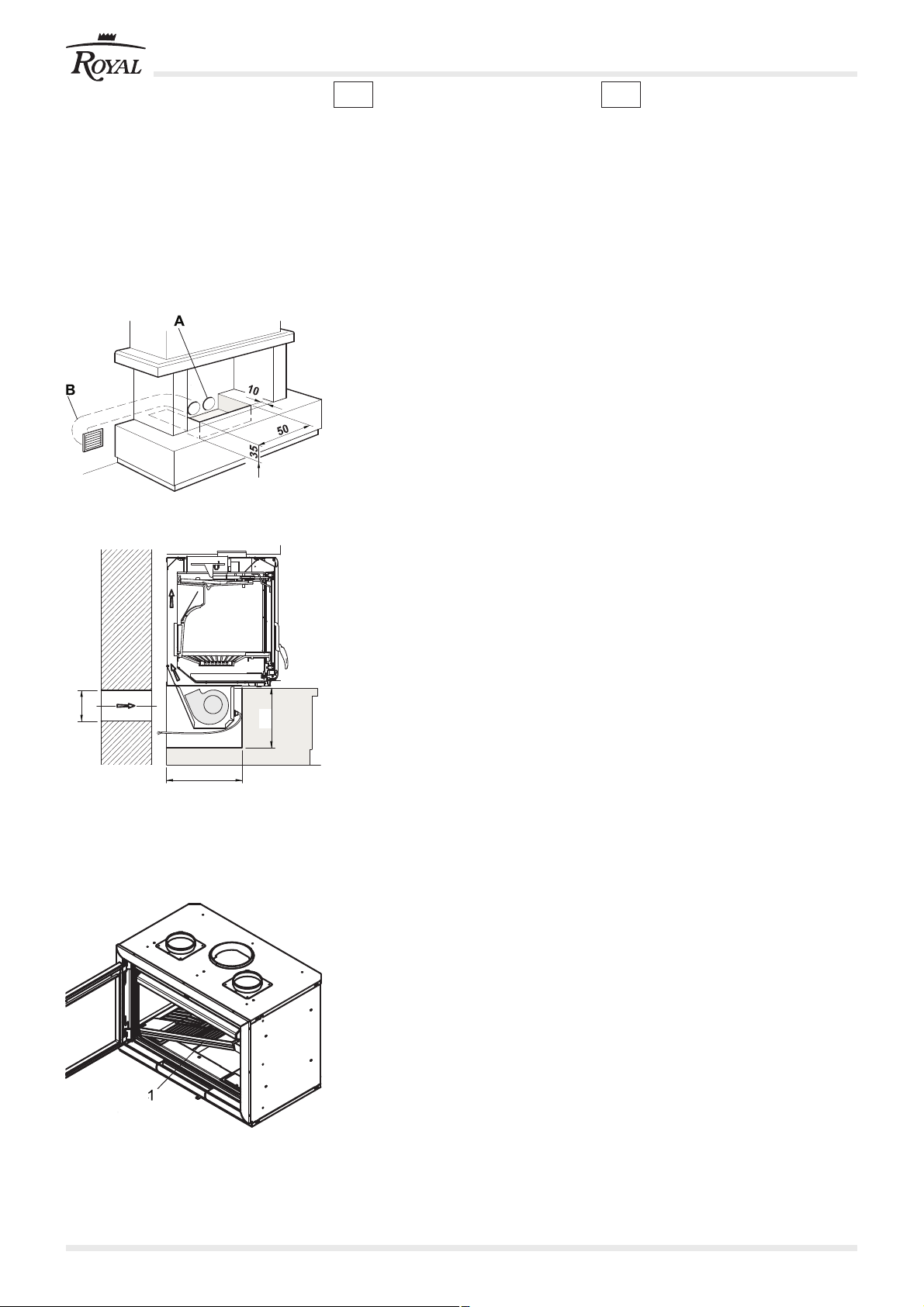
A
Presa d’aria esterna Ø 14.
External air intake Ø 14.
Prise d’air extérieure Ø 14.
Lüftungsöffnung nach außen Ø 14.
Toma de aire externa Ø 14.
B
Ripresa d’aria interna / esterna Ø 14.
Internal/external air suction Ø 14.
Reprise d’air intérieur / extérieure Ø 14.
Luftzufuhr innen / außen Ø 14.
Toma de aire interna/ externa Ø 14.
Fig. 1
1 VENTILATORE “680”
Il ventilatore 680 é stato studiato per
essere applicato sull’Inserto e consente
di distribuire aria calda su più locali
ampliando in modo considerevole le
prestazioni del caminetto.
1.1 PRESE D’ARIA (FIG.1 E 2)
Il ventilatore necessita di una presa d’aria,
possibilmente esterna, avente un
diametro di 14 cm.
La presa d’aria potrà essere posizionata
sul retro o sul fianco del caminetto ed in
modo da consentire l’afflusso di aria al
vano caminetto e al ventilatore.
La presa d’aria se è collegata all’esterno
svolge la funzione anche di ripresa aria
comburente.
In alternativa può essere utilizzata una
ripresa d’aria interna.
1 “680” FAN
The 680 fan is designed for installation
on the Inserto and makes it possible to
distribute warm air to several rooms, thus
substantially enhancing the performance
of the fireplace.
1.1 AIR INTAKES (FIGS.1 AND 2)
The fan requires an air intake with a
diameter of 14 cm, which if possible
should be located externally.
The air intake can be located on the rear
or side of the fireplace in order to allow a
flow of air into the fireplace compartment
and to the fan.
If the air intake is connected to the exterior,
it also acts as a combustion air intake.
An internal air intake can be used as an
alternative.
Ø 14
C
C
Presa d'aria esterna.
External air intake.
Prise d’air extérieure.
Lüftungsöffnung nach außen.
35
35
Fig. 2
1.2 ALLOGGIAMENTO (FIG.1 E 2)
Per i caminetti esistenti predisporre un
vano tecnico sotto la base dell’Inserto per
alloggiare il ventilatore, di dimensioni
almeno pari a quanto indicato nelle figure.
1.3 INSTALLAZIONE DEL
VENTILATORE (FIG. 3)
Aprire la portina togliere la griglia e la base
in ghisa (1).
1.2 HOUSING (FIGS. 1 AND 2)
For existing fireplaces, there must be a
compartment under the Inserto base to
house the fan. Its dimensions must be
as indicated in the figures.
1.3 INSTALLING THE FAN (FIG. 3)
Open the door and remove the grille and
cast iron base (1).
Fig. 3
2/12 cod. 004722623 - 04/2011 KIT VENTILAZIONE
Page 3
ESFD
1 VENTILATOR “680”
Der Ventilator 680 ist entwickelt worden,
umin den Inserto für die Verteilung der
Warmluft eingesetzt zu werden, die
Leistungen des Kaminofens werden
dadurch beträchtlich erhöht.
1.1 LÜFTUNGSKLAPPEN (ABB.1
UND 2)
Für den Ventilator ist eine Lüftungsklappe,
möglichst extern, notwendig, die einen
Durchmesser von 14 cm haben soll.
Die Lüftungsklappe kann auf der
Rückseite oder auf der Aussenseite des
Kaminofens angebracht werden und
muss den Luftstrom zum Kaminofen und
zum Ventilator leiten.
Wenn die Luftungsklappe ins Freie führt,
erfüllt sie auch die Aufgabe der
Verbrennungsluftzufuhr.
Alternativ kann eine interne Luftzufuhr
verwendet werden.
1 VENTILATEUR “680”
Le ventilateur 680 a été conçu pour être
monté sur l’Inserto et permet de distribuer
l'air chaud dans plusieurs pièces en
augmentant considérablement les
performances de la cheminée.
1.1 PRISE D’AIR (FIG.1 ET 2)
Le ventilateur nécessite d'une prise d'air,
si possible extérieure, de 12 cm de
diamètre.
La prise d'air pourra être montée au dos
ou sur le côté de la cheminée et de façon
à permettre l'afflux d'air au compartiment
cheminée et au ventilateur.
Lorsqu'elle est raccordée à l'extérieur, la
prise d’air sert également de reprise d'air
comburant.
En alternative, on pourra utiliser une
reprise d’air intérieure.
1 VENTILADOR “680”
El ventilador 680 ha sido estudiado para
su aplicación en el Inserto y permite la
distribución de aire caliente en varios
locales, ampliando de forma
considerable las prestaciones de la
chimenea.
1.1 TOMAS DE AIRE (FIGS. 1 Y 2)
El ventilador necesita de una toma de aire,
a ser posible externa, con un diámetro de
14 cm.
La toma de aire puede colocarse en la
parte trasera o en el lateral de la
chimenea, y debe permitir el flujo de aire
al hueco de la chimenea y al ventilador.
La toma de aire, si está conectada con el
exterior, también actúa como toma de aire
comburente.
En alternativa se puede utilizar una toma
de aire interior.
1.2 UNTERBRINGUNG (ABB. 1
UND 2)
Für bereits bestehende Kamine, unter
dem Unterteil des INSERTO ein Fach für
die Unterbringung des Ventilators
vorbereiten. Die diesbezüglichen Maße
sollten der Abbildung entsprechen.
1.3 INSTALLATION DES
VENTILATORS (ABB. 3)
Die Tür öffnen, den Rost und die
Gusseisenplatte abnehmen (1).
1.2 LOGEMENT (FIG. 1 ET 2)
Sur les cheminées existantes, prévoir un
logement technique sous la base de l'
INSERTO pour placer le ventilateur; les
dimensions doivent être au moins égales
à celles indiquées sur les schémas.
1.3 INSTALLATION DU
VENTILATEUR (FIG. 3)
Ouvrir la porte et retirer la grille et la base
en fonte (1).
1.2 ALOJAMIENTO (FIGS. 1 Y 2)
Para las chimeneas existentes, disponer
un compartimento técnico debajo de la
base del Inserto para alojar el ventilador,
de tamaño al menos igual a lo que está
indicado en la figura.
1.3 INSTALACIÓN DEL
VENTILADOR (FIG. 3)
Abrir la puerta y quitar la rejilla y la base
de hierro fundido (1).
KIT VENTILAZIONE cod. 004722623 - 04/2011 3/12
Page 4
IT GB
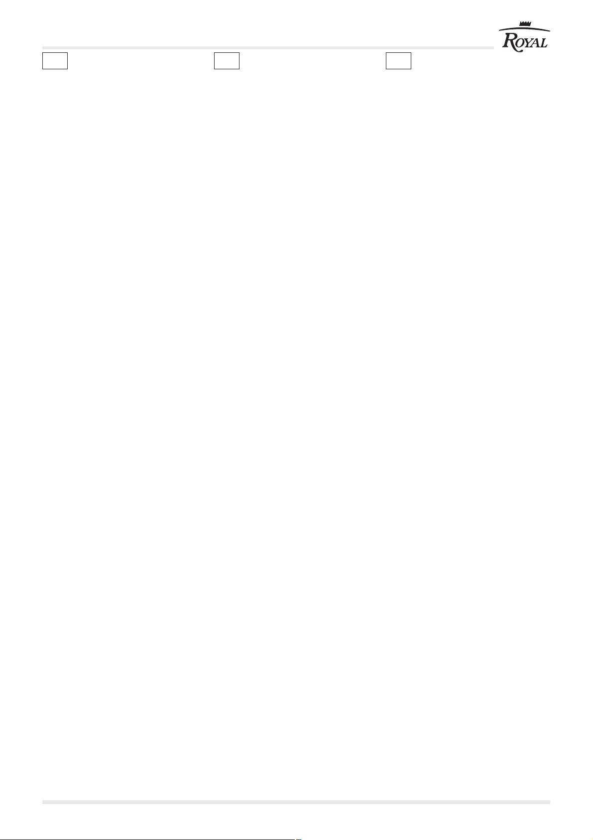
1.4 ESTRAZIONE DEL
CONTROCASSETTO (FIG. 4)
Togliere il cassetto cenere (2).
Togliere il controcassetto (3) svitando le
viti (V).
Togliere la chiusura in lamiera (4)
rimuovendo le viti (V1) e (V2) per accedere
al vano tecnico sottostante.
1.4 REMOVING THE COUNTER
BOX (FIG. 4)
Remove the ash box (2).
Remove the counter box (3) by unscrewing
the screws (V).
Remove the closing sheet (4) by
unscrewing the screws (V1) and (V2) to
access the compartment underneath.
Fig. 4
V
V1
4
3
Fig. 4-a
V2
Fig. 4-b
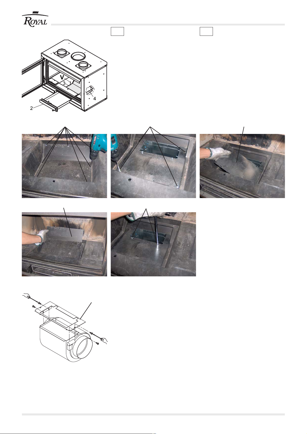
1.5 PREMONTAGGIO
5
VENTILATORE (FIG. 5)
Montare la flangia 5 sul ventilatore (Fig.
5).
Fig. 4-c
Fig. 4-d
1.5 FAN PRE-ASSEMBLY (FIG. 5)
Assemble the flange 5 on the fan (Fig. 5).
Fig. 4-e
Fig. 5
4/12 cod. 004722623 - 04/2011 KIT VENTILAZIONE
Page 5

ESFD
1.4 AUSZUG DES
AUSSENKASTENS (ABB. 4)
Die Aschenlade herausnehmen (2).
Den Aussenkasten (3) durch
Ausschrauben der Schrauben (V)
abnehmen.
Den Blechverschluss (4) Ausschrauben
der Schrauben (V1) und (V2) abnehmen,
um den Zugang zum unteren Fach zu
ermöglichen.
1.4 EXTRACTION DU CONTRETIROIR (FIG. 4)
Retirer le tiroir à cendres (2).
Retirer le contre-tiroir (3) en dévissant les
vis (V).
Retirer la fermeture en tôle (4) en
dévissant les vis (V1) et (V2) pour accéder
au logement technique du dessous.
1.4 EXTRACCIÓN DEL
CONTRACAJÓN (FIG. 4)
Retirar el cajón de la ceniza (2).
Quitar el contracajón (3) aflojando los
tornillos (V).
Quitar el cierre de chapa (4) aflojando los
tornillos (V1) en (V2) para tener acceso al
compartimento técnico de abajo.
1.5 VORBEREITUNG DES
VENTILATORS (ABB. 5)
Den Flansch 5 am Ventilator montieren
(Abb. 5).
1.5 PRÉ-MONTAGE DU
VENTILATEUR (FIG. 5)
Monter la bride 5 sur le ventilateur (Fig. 5).
1.5 PREMONTAJE VENTILADOR
(FIG. 5)
Montar la brida 5 en el ventilador (Fig. 5).
KIT VENTILAZIONE cod. 004722623 - 04/2011 5/12
Page 6

IT GB
Passare il cavo di alimentazione 6
attraverso il foro della staffa di supporto e
1
2
fissarlo alla morsettiera (Fig. 6).
6
Pass the power cable 6 through the hole
in the supporting bracket and secure it to
the terminal board (Fig. 6).
Fig. 6
1.6 INSERIMENTO DEL
VENTILATORE (FIG. 7)
Inserire il ventilatore nel vano dell’Inserto
e fissarlo con le viti.
1.6 INSERTION OF THE FAN (FIG.
7)
Insert the fan in the Inserto compartment
and secure it with the screws.
Fig. 7
Fig. 8
Posizionare e fissare la piastra.
Position and fasten the plate.
6/12 cod. 004722623 - 04/2011 KIT VENTILAZIONE
Page 7

ESFD
Das Stromkabel durch die Bohrung im
Haltebügel führen und es an der
Klemmenleiste befestigen (Abb. 6).
1.6 EINBAU DES VENTILATORS
(ABB. 7)
Den Ventilator in das Fach des Inserto
einführen und ihn mit den Schrauben
befestigen.
Faire passer le câble d'alimentation 6 à
travers l'orifice de l'étrier de support et le
fixer au bornier (Fig. 6).
1.6 POSE DU VENTILATEUR (FIG.
7)
Poser le ventilateur dans le compartiment
de l'Inserto et le fixer avec les vis.
Pasar el cable de alimentación 6 a través
del orificio de la brida de soporte y fijarlo
a la bornera (Fig. 6).
1.6 INTRODUCCIÓN DEL
VENTILADOR (FIG. 7)
Introducir el ventilador en el
comaprtimento del Inserto y fijarlo con los
tornillos.
Die Platte positionieren und befestigen.
Positionner et fixer la plaque.
Colocar y fijar la placa.
KIT VENTILAZIONE cod. 004722623 - 04/2011 7/12
Page 8

INSERIMENTO TAMPONI ANTERIORI
IT GB
Fig. 9
Fig. 10
1.7 INSERIMENTO TAMPONI
ANTERIORI (FIG. 9)
Togliere i tappi (6) posti sul frontale sotto
la base in ghisa.
Inserire i due tamponi di chiusura frontale
(7) avvitandoli dalla parte anteriore della
stufa.
Ricollocare e riavvitare i tappi (6).
Nel caso del kit di ventilazione opzionale
riavvitare i tappi (6) dopo aver montato il
termostato.
PERICOLO
Accertarsi che non vi sia tensione
nell’allacciamento all’Inserto prima di
ogni operazione.
1.8 COLLEGAMENTI ELETTRICI
1.8.1 Installazine ventilazione
frontale
Avvitare il termostato (8) sulla struttura del
focolare in basso a sinistra.
Collegare il cavo con 2 fili al termostato
(8) mediante i faston.
Collegare il cavo di alimentazione (E) al
ventilatore.
La centralina (9) deve essere installata
lontano dalle fonti di calore e con modalità
contenute nell’apposito foglio.
1.7 INSERTION OF FRONT
BUMPERS (FIG. 9)
Remove the plugs (6) located on the front
under the cast iron base.
Insert the two front closure bumpers (7)
screwing them in from the front part of the
stove.
Put the plugs back in place and screw
them back in (6).
For the optional ventilation kit, screw the
plugs back in (6) after installing the
thermostat.
DANGER
prior to each job, make sure there is no
power to the Inserto connection.
1.8 ELECTRICAL CONNECTION
1.8.1 Installation of optional
ventilation kit
Screw the thermostat (8) onto the
structure of the firebox at lower left.
Connect the 2-wire cable to the thermostat
(8) with the fastons.
Connect the power cord (E) to the fan.
The control unit (9) must be installed far
from heat sources and as shown in the
instruction sheet.
Fig. 11
1.8.2 Installazione ventilazione
canalizzata
Installare la sonda (12) nel tubo
convogliatore aria tramite l'apposito
fermasonda.
Collegare la sonda (12) al alla centralina
(10) con il cavo (11).
Collegare il cavo di alimentazione (E) al
ventilatore.
La centralina (10) deve essere installata
lontano dalle fonti di calore e con modalità
contenute nell’apposito foglio.
1.8.2 Installation of optional
ventilation kit + hood kit
Install the sensor (12) in the air duct using
the appropriate sensor holder.
Connect the sensor (12) to the control unit
(10) with the cable (11).
Connect the power cord (E) to the fan.
The control unit (10) must be installed far
from heat sources and as shown in the
instruction sheet.
8/12 cod. 004722623 - 04/2011 KIT VENTILAZIONE
Page 9

ESFD
1.7 EINSETZEN DER VORDEREN
PUFFER (FIG. 9)
Die Kappen (6) auf der Vorderseite unter
dem Unterteil aus Gusseiseb,
abnehmen.
Die zwei vorderen Abschlusspuffer (7)
einsetzenund am vorderen Teil des
Heizofens festschrauben.
Die Kappen (6) wieder einsetzen und
anschrauben.
Beim zusätzlichen Ventilationsbausatz, die
Kappen (6)nach der Montage des
Thermostats wieder anschrauben.
GEFAHR
Vor jedem Eingriff sicherstellen, dass in
den Stromleitungen zum Inserto keine
Spannung vorhanden ist.
1.8 STROMANSCHLÜSSE
1.8.1 Installation zusätzlicher
Ventilationsbausatz
Das Thermostat (8) unten links am
Korpus des Feuerraums anschrauben.
Das 2-drähtige Kabel mittels
Fastonstecker am Thermostat (8)
anschließen.
Das Stromkabel (E) am Lüfter
anschliessen.
Die Steuereinheit (9) muss von den
Wärmequellen entfernt installiert werden
und zwar entsprechend den Anweisungen
des Beiblattes.
1.8.2 Installation zusätzlicher
Ventilationsbausatz +
Bausatz Abzugshaube
Den Fühler (12) in der Luftrohrleitung mit
der entsprechenden Fühlerhalterung
installieren.
Den Fühler (12) an der Steuereinheit(10)
mit dem Kabel (11) anschliessen.
Das Stromkabel (E) am Lüfter
anschliessen.
Die Steuereinheit (10) muss von den
Wärmequellen entfernt installiert werden
und zwar entsprechend den Anweisungen
des Beiblattes.
1.7 POSE TAMPONS ANTÉRIEURS
(FIG. 9)
Oter les bouchons (6) situés sur la façade
sous la base en fonte.
Poser les deux tampons de fermeture
frontale (7) en les vissant à partir de la
partie antérieure du poêle.
Replacer et revisser les bouchons (6).
Avec le kit de ventilation en option revisser
les bouchons (6) après avoir monté le
thermostat.
DANGER
Vérifiez qu'il n'y ait pas de tension dans
le raccordement à l’Inserto avant chaque
opération.
1.8 RACCORDEMENTS
ÉLECTRIQUES
1.8.1 Installation de la ventilation
frontale
Visser le thermostat (8) sur la structure
du foyer en bas à gauche.
Raccorder le câble à deux fils au
thermostat (8) avec les fastons.
Raccorder le câble d'alimentation (E) au
ventilateur.
La centrale (9) doit être installée loin des
sources de chaleur et selon les modalités
présentées dans la page d'instructions.
1.8.2 Installation du Kit
Ventilation en option + Kit
hotte
Monter la sonde (12) dans le conduit d'air
au moyen du serre-sonde prévu à cet effet
Raccorder la sonde (12) au tableau
électrique (10) avec le câble (11).
Raccorder le câble d'alimentation (E) au
fan.
La tableau électrique (10) doit être installé
loin des sources de chaleur et selon les
modalités présentées dans la page
d'instructions.
1.7 INCORPORACIÓN DE LOS
TAMPONES ANTERIORES (FIG.
9)
Quitar los tapones (6) ubicados en el
frontal, bajo la base de hierro fundido.
Introducir los dos tampones del cierre
frontal (7), enroscándolos desde la parte
delantera de la estufa.
Volver a colocar y a enroscar los tapones
(6).
En el caso de Kit de ventilación opcional,
volver a enroscar los tapones (6) tras
haber montado el termostato.
PELIGRO
Comprobar que no hay tensión en la
conexión con el INSERTO antes de
cualquier operación.
1.8 CONEXIONES ELÉCTRICAS
1.8.1 Instalación del Kit de
ventilación opcional
Enroscar el termostato (8) en la estructura
del hogar, en la parte inferior izquierda.
Conectar el cable de 2 hilos al termostato
(8) mediante los faston.
Conectar el cable de alimentación (E) al
abanico.
La centralita (9) debe instalarse alejada
de las fuentes de calor, según las
modalidades descritas en la hoja
correspondiente.
1.8.2 Instalación del Kit de
ventilación opcional + Kit
campana
Instalar la sonda (12) en el tubo de
canalización de aire usando el retén para
sonda adecuado.
Conectar la sonda (12) a la centralita (E)
con el cable (11).
Conectar el cable de alimentación (C) al
abanico.
La centralita (10) debe instalarse alejada
de las fuentes de calor, según las
modalidades descritas en la hoja
correspondiente.
KIT VENTILAZIONE cod. 004722623 - 04/2011 9/12
Page 10

IT GB
Fig. 12
1.9 RIASSEMBLAGGIO
DELL’INSERTO
Riposizionare nella propria sede il
controcassetto avendo cura di fissarlo
mediante le viti precedentemente tolte,
avendo cura di sostitire la guarnizione nel
caso in cui fosse rovinata.
NB: Una cattiva sigillatura sarà causa di
aspirazione di fumi dal ventilatore il quale
li manderà in ambiente con conseguente
odore di fumo in casa.
Rimontare tutte le altre parti avendo cura
di posizionarle correttamente.
Il ventilatore funzionerà solo a caminetto
acceso e si avvierà dopo circa 15-20
minuti dall’accensione.
1.10 MANCATO FUNZIONAMENTO
DEL VENTILATORE
Accertarsi che ci sia tensione alla
centralina;
che il fusibile non sia bruciato;
che il termostato sia efficiente;
la temperatura di intervento é di 46 °C.
1.9 REASSEMBLING THE
INSERTO
Replace the counter box in its housing,
making sure to fasten it by means of the
previously removed screws, and replace
the gasket if it has been damaged.
NB: Bad sealing will cause the fan to take
in smoke which it will release into the
room, leaving a smell of smoke in the
home.
Re-assemble all the parts, positioning
them correctly.
The fan will work only when the fireplace
is lit, and it will start up about 15-20
minutes after lighting.
1.10 FAILURE OF FAN TO WORK
Make sure the control unit is
powered;
that the fuse has not blown;
Check that the thermostat is
working properly; activation
temperature is 46°C.
Fig. 13
1.11 DISTRIBUZIONE DELL’ARIA
CALDA SU PIÙ LOCALI
Esempio di condutture canalizzate.
Portate ottimali d’aria si ottengono con
condutture di lunghezza massima di 2
metri in per singolo canale e di 6 metri in
canale singolo.
Lunghezze maggiori possono essere
eseguite tenendo presente che riducono
la portata d’aria.
Per una maggiore resa isolare le
condutture con lana di vetro.
Dati elettrici:
Alimentazione elettrica: 230 V, 50 Hz
1.11 DISTRIBUTION OF WARM AIR
TO SEVERAL ROOMS
Example of ducting.
Best air flow rates are obtained with ducts
with a maximum length of 2 metres for
dual ducts and 6 metres for a single duct.
Greater lengths can be used, but they will
reduce the air flow rate.
For greater performance, insulate the
ducts with fibreglass wool.
Electrical data:
Electrical power supply: 230 V, 50 Hz
10/12 cod. 004722623 - 04/2011 KIT VENTILAZIONE
Page 11

ESFD
1.9 ERNEUTER ZUSAMMENBAU
DES INSERTO
Den Aussenkasten wieder in seinen Sitz
einbringen und ihn dabei mit den vorher
entfernten Schrauben befestigen, falls die
Dichtung beschädigt worden ist, muss
sie ausgewechselt werden.
ANMERKUNG: Bei schlechter
Versiegelung, vor allem des
Aschenkastens, saugt der Ventilator
Rauch an, den er dann in den Raum
weiterleitet. Das führt zu unangenehmem
Rauchgeruch im Haus.
Alle Teile wieder korrekt montieren.
Der Ventilator funktioniert nur bei
brennendem Kaminofen und startet
ungefähr 15-20 Minuten nach dem
Anzünden.
1.10 KEIN VENTILATORBETRIEB
Sich vergewissern, dass die Steuereinheit
Spannung hat;
Sicherstellen, dass die Sicherung nicht
durchgebrannt ist.
Den Thermostat auf seinen Betrieb
kontrollieren; die Eingriffstemperatur
beträgt 46°C.
1.11 VERTEILUNG DER WARMLUFT
IN MEHRERE RÄUME
Beispiel der kanalisierten Luftleitungen.
Die beste Luftmengenverteilung erzielt
man mit maximalen Leitungslängen von
2 Metern in doppelten Kanälen und von 6
Metern bei einzelnen Kanälen.
Grössere Längen können verlegt werden,
aber sie reduzieren die Warmluftmenge.
Für eine bessere Leistung, die leitungen
mit Glaswolle isolieren.
Elektrische Daten:
Stromversorgung: 230 V, 50 Hz
1.9 REMONTAGE DE L’INSERTO
Replacer le contre-tiroir dans son
logement en veillant à le fixer au moyen
des vis qui avaient été enlevées
précédemment, et en ayant soin de
remplacer le joint au cas où il serait
endommagé.
NB. Un mauvais jointoiement causera
l'aspiration des fumées par l'aspirateur
qui les renverra dans la pièce, ce qui
provoquera une odeur de fumée dans la
maison.
Remonter tous les autres éléments en
veillant à les remettre dans la bonne
position.
Le ventilateur ne fonctionnera qu'avec la
cheminée allumée et démarrera environ
15-20 minutes après l'allumage.
1.10 SI LE VENTILATEUR NE
FONCTIONNE PAS
Vérifiez la présence de tension à la
centrale.
Vérifiez que le fusible n'ait pas sauté.
Contrôlez que le thermostat soit efficient.
la température de déclenchement est de
46°C.
1.11 DISTRIBUTION DE L'AIR
CHAUD DANS PLUSIEURS
PIÈCES
Exemple de conduites canalisées.
Des débits d'air optimaux s'obtiennent
avec des conduites d'un maximum de 2
mètres de long pour les conduits doubles
et de 6 mètres pour les conduits simples.
Des longueurs supérieures peuvent être
exécutées en considérant qu'elles
réduisent le débit d'air.
Pour un rendement majeur, isolez les
conduites avec de la laine de verre.
Données électriques:
Alimentation électrique: 230 V, 50 Hz
1.9 ENSAMBLAJE DEL INSERTO
Poner en su alojamiento el contracajón,
prestando atención a fijarlo mediante los
tornillos que se han quitado
anteriormente, y sustituyendo la
guarnición en caso de que estuviera
desgastada.
Nota: El sellado incorrecto, puede causar
la aspiración de los humos por parte del
ventilador, que los dirigirá hacia el cuarto,
produciendo el consiguiente olor a humo.
Volver a montar todas las piezas cuidando
que se dispongan debidamente.
El ventilador sólo funcionará con la
chimenea encendida, y exclusivamente
después de que hayan transcurrido de
15 a 20 minutos del encendido.
1.10 FUNCIONAMIENTO ERRADO
DEL VENTILADOR
Comprobar que haya tensión hacia la
centralita;
comprobar que el fusible no se haya
fundido;
controlar la eficiencia del termostato; la
temperatura de actuación es de 46°C.
1.11 DISTRIBUCIÓN DE AIRE
CALIENTE EN DISTINTOS
LOCALES
Ejemplo de conductos canalizados.
Los mejores caudales de aire se
obtienen con conductos de una longitud
máxima de 2 metros para canales dobles
y de 6 metros para canales simples.
Esto no es posible con longitudes
mayores, ya que reducen el caudal de
aire.
Para obtener un mayor rendimiento, aislar
los conductos con lana de vidrio.
Datos eléctricos:
Alimentación eléctrica: 230 V, 50 Hz
KIT VENTILAZIONE cod. 004722623 - 04/2011 11/12
Page 12

cod. 004722623 versione aprile 2011 Studio 7 s.r.l.
La Ditta non si assume alcuna responsabilità per eventuali errori del presente opuscolo e si ritiene
libera di variare senza preavviso le caratteristiche dei propri prodotti.
The manufacturer accepts no liability for any mistakes in this handbook and is free to modify the features
of its products without prior notice.
Le fabricant décline toute responsabilité en cas d’erreurs dans la présente documentation et conserve
la faculté de modifier sans préavis les caractéristiques de l’appareil.
Die Firma übernimmt für eventuelle Fehler in diesem Heft keine Verantwortung und behält sich das
Recht vor, die Eigenschaften ihrer Produkte ohne Vorbescheid zu ändern.
La empresa no se responsabiliza de los errores eventuales de este manual y tiene el derecho de
modificar sin previo aviso las características de sus productos.
GRUPPO PALAZZETTI
Via Roveredo, 103
33080, Porcia (PN) - Italy
Tel. 0434 45111
Telefax 0434 538204
Internet: www.royal1915.it
E-mail: info@royal1915.it
12/12 cod. 004722623 - 04/2011 KIT VENTILATORE
 Loading...