

Page 1
IN-E-HyLab-V4_11
Document code Unit
Rotronic AG
Bassersdorf, Switzerland
HygroLab bench top indicator version 4:
instruction manual
Document title
HygroLab Bench Top Indicator version 4
Instruction Manual
Instruction Manual
Document Type
Page 1 of 51
© 2006; Rotronic AG IN-E-HyLab-V4_11
Page 2

IN-E-HyLab-V4_11
Document code Unit
Rotronic AG
Bassersdorf, Switzerland
HygroLab bench top indicator version 4:
instruction manual
Document title
Instruction Manual
Document Type
Page 2 of 51
Table of contents
1 Overview ....................................................................................................................................3
2 General description ..................................................................................................................4
2.1 Power requirements................................................................................................................4
2.2 Probes and probe inputs.........................................................................................................4
2.3 Analog outputs (optional) ........................................................................................................6
2.4 Serial interface (HygroLab 2 and 3)........................................................................................7
2.5 Optional Ethernet (TCP/IP) interface (HygroLab 2 and 3)......................................................9
3 Optional configuration and communication software ........................................................10
4 How to configure the HygroLab ............................................................................................10
4.1 Internal service connector (HygroLab configuration)............................................................10
4.2 Baud rate compatibility requirements ...................................................................................11
4.3 Ethernet local area network ..................................................................................................11
4.4 RS-485 multi-drop network (HygroLab 2 and 3)...................................................................12
4.5 Selection of the probe supply voltage (main PCB) ...............................................................14
5 Operation.................................................................................................................................14
5.1 Unit system ...........................................................................................................................15
5.2 Display and keypad...............................................................................................................15
5.3 Probe Input Selection............................................................................................................16
6 Function menu ........................................................................................................................16
6.1 CALCULATE (HygroLab 2 and 3).........................................................................................17
6.2 MODE (HygroLab 3) .............................................................................................................18
6.3 DISPLAY (HygroLab 2 and 3)...............................................................................................21
6.4 ADJUST M.PT ......................................................................................................................21
6.5 ADJUST 1PT.........................................................................................................................23
6.6 ADJUST REF........................................................................................................................24
6.7 PROBE..................................................................................................................................25
6.8 SETTINGS ............................................................................................................................25
6.9 SYS STATUS........................................................................................................................26
7 Error and status messages....................................................................................................26
8 Connectors..............................................................................................................................27
9 Environmental limits ..............................................................................................................28
10 Maintenance of the ROTRONIC probes ................................................................................29
11 Specifications..........................................................................................................................30
12 Practical advice for measuring humidity .............................................................................31
13 Probe calibration basics ........................................................................................................31
13.1 Temperature calibration ........................................................................................................31
13.2 Humidity calibration...............................................................................................................32
14 Humidity definitions ...............................................................................................................33
15 Dew point accuracy ................................................................................................................36
16 ASCII communications protocol ...........................................................................................37
17 Water activity measurement ..................................................................................................40
17.1 Water activity: definition and applications.............................................................................40
17.2 Using the HygroLab 2 or 3 to measure water activity...........................................................42
17.3 Principle of measurement .....................................................................................................43
17.4 General recommendations....................................................................................................44
17.5 Using the AwE mode (HygroLab 3) ......................................................................................45
17.6 Using the AwQuick mode (HygroLab 3) ...............................................................................47
18 Accessories for the HygroLab...............................................................................................50
19 Document releases.................................................................................................................51
© 2006; Rotronic AG IN-E-HyLab-V4_11
Page 3

IN-E-HyLab-V4_11
Document code Unit
Rotronic AG
Bassersdorf, Switzerland
HygroLab bench top indicator version 4:
instruction manual
Document title
Instruction Manual
Document Type
Page 3 of 51
Applicability:
This manual is valid for all instruments with firmware version 4.x, where 4.x can be 4.0, 4.1, etc.
(see Function Menu, SYS STATUS). Changes to the last digit of the version number reflect minor
firmware changes that do not affect the manner in which the instrument should be operated.
Note: Instrument configuration requires a PC with the optional ROTRONIC HW4 software version
1.2.2 or higher. Instructions for using the software are not included in this manual. These
instructions are shipped separately on the software CD ROM.
1 Overview
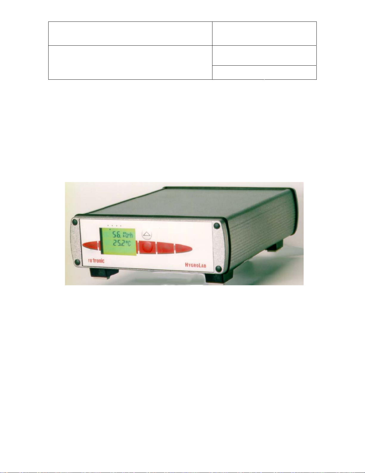
The HygroLab is a bench-top laboratory humidity temperature indicator that can be used with a
wide variety of probes to meet specific application requirements. The HygroLab operates with an
external AC adapter (9 to 15 VDC – nominal: 12 VDC).
The HygroLab is available in 3 different models:
HygroLab 1: basic indicator
- Accepts up to 2 probes: ROTRONIC HygroClip digital probes or analog probes
- Simultaneous display of relative humidity and temperature (one probe at a time)
- Software-based probe calibration (1-point or multi-point)
2)
1) ROTRONIC analog probes only – restrictions apply
2) Applies only to the ROTRONIC HygroClip digital probes
HygroLab 2: standard indicator
- Accepts up to 4 probes: ROTRONIC HygroClip digital probes or analog probes
- Relative humidity, temperature, dew point, wet bulb, mixing ratio, enthalpy, etc., or user
defined calculation such as the difference between temperature and dew point
- Software-based probe calibration (1-point or multi-point)
- Possibility of using one of the four probes as a reference to do a 1-point adjustment of the
other probes
3)
- RS232 and RS485 serial ports or Ethernet (TCP/IP), RS-232 and RS-485 ports
- Optional analog outputs (repeat analog probe input signals)
1) Third-party pressure probe or ROTRONIC analog probe – restrictions apply
2) Uses either a fixed barometric pressure value or the measurements from an analog pressure probe
for those parameters that require pressure as a computational input. The fixed pressure value can be
changed with the optional HW4 software.
3) Applies only to the ROTRONIC HygroClip digital probes
4) The optional HW4 software facilitates both networking and instrument configuration
3)
1)
1)
2)
4)
© 2006; Rotronic AG IN-E-HyLab-V4_11
Page 4
IN-E-HyLab-V4_11
Document code Unit
Rotronic AG
Bassersdorf, Switzerland
HygroLab bench top indicator version 4:
Instruction Manual
instruction manual
Document title
HygroLab 3: general purpose indicator with water activity functions
Same as HygroLab 2, except for:
- Accelerated water activity measurement with up to 4 probes (AwQuick mode): allows the
measurement of most products in typically 5 minutes
- Full equilibration measurement with up to 4 probes (Standard mode) with automatic
detection of equilibrium conditions
- Analog probe inputs with 12-bit resolution
HygroLab 1 HygroLab 2 and 3
Page 4 of 51
Document Type
2 General description
2.1 Power requirements
The HygroLab operates with an external AC adapter providing 9 to15 VDC, 100 mA. The power
receptacle is a 3.5 mm Jack female with DC+ center.
Note: when equipped with the optional Ethernet module, the HygroLab requires an AC adapter
able to provide 300 mA.
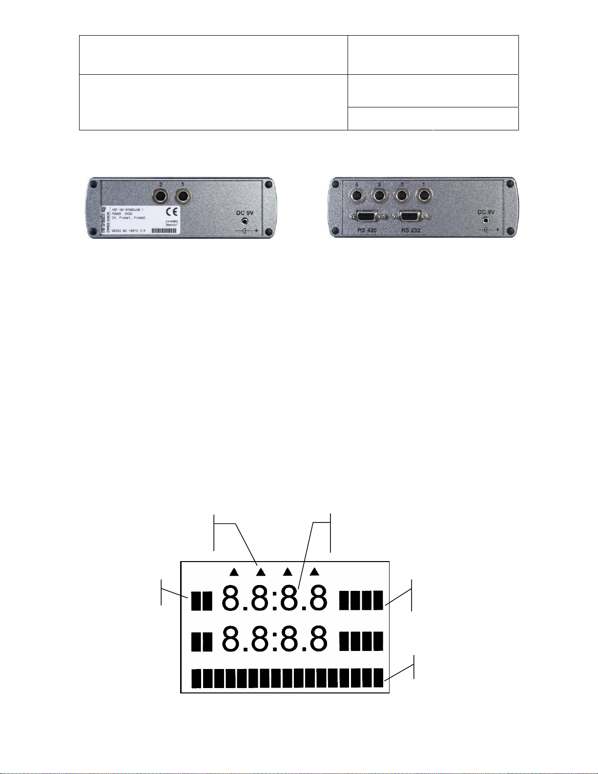
2.2 Probes and probe inputs
Model HygroLab 1 HygroLab 2 HygroLab 3
Number of probe inputs 2 4 4
Probe types 1) ROTRONIC Digital
ROTRONIC Analog
Number of digital input channels 2 4 4
Number of analog input channels 4 8 8
Analog input A/D resolution 10-bit 10-bit 12-bit
1) Unless otherwise specified when ordering, all probe inputs are factory programmed to accept a HygroClip
digital probe and the voltage powering the probe is the AC adapter voltage (12 VDC nominal). Prior to using
any analog probe, the corresponding probe input should be re-programmed. With the HygroLab 2 and 3, this
can be done with the HW4 software after connecting the RS232 port of the HygroLab to a PC (see separate
software manual).
ROTRONIC Digital
ROTRONIC Analog
Third Party Analog
ROTRONIC Digital
ROTRONIC Analog
Third Party Analog
© 2006; Rotronic AG IN-E-HyLab-V4_11
Page 5
IN-E-HyLab-V4_11
(
(
Document code Unit
Rotronic AG
Bassersdorf, Switzerland
HygroLab bench top indicator version 4:
instruction manual
Document title
Instruction Manual
Document Type
Page 5 of 51
IMPORTANT: All probes connected to the HygroLab can be supplied with 5 VDC by opening solder pad B12
and closing solder pad B13 on the main PCB
. – see page 13: selection of the probe supply voltage.
2.2.1 HygroClip digital probes
The HygroLab is primarily designed for use with the ROTRONIC HygroClip digital humidity
temperature probes. These probes permit to take full advantage of all the features and functions of
the HygroLab.
The ROTRONIC HygroClip digital probes are highly accurate and are calibrated entirely by means
of software (no adjustment potentiometers). Because calibration and other data are stored in the
probe non-volatile memory, the probes are fully interchangeable. When a probe requires calibration
or has to be repaired, it can be replaced with another probe in a few seconds.
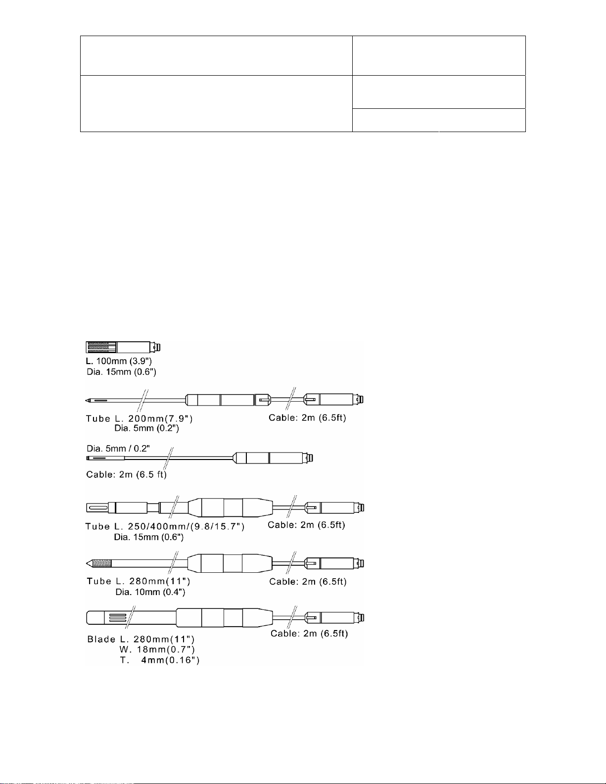
The ROTRONIC HygroClip digital probes are available in different configurations so as to meet the
requirements of each application:
HygroClip S
measurement in air
max. 85°C (185°F)
HygroClip SP05
measurement in air ducts
max. 85°C (185°F)
HygroClip SC05
measurement in tight spaces
max. 100°C (212°F)
HygroClip HK25 / HK40 air probe
measurement at high temperature
HK25: max. 100°C (212°F)
HK40: max. 200°C (392°F)
wire mesh filter
HygroClip HP28 insertion probe
measurement of materials in bulk
max. 85°C
185°F)
HygroClip HS28 sword probe
measurement of paper stacks/rolls
max. 85°C
185°F)
Note: all of the above probes are designed for use with the HygroPalm indicator and have a
DAT05 connector. An adapter cable MOK-01-B5 is required for connection to the HygroLab (see
Accessories). Similarly, the HygroClip probes designed for use with the HygroFlex transmitter
© 2006; Rotronic AG IN-E-HyLab-V4_11
Page 6
IN-E-HyLab-V4_11
Document code Unit
Rotronic AG
Bassersdorf, Switzerland
HygroLab bench top indicator version 4:
instruction manual
Document title
Instruction Manual
Document Type
Page 6 of 51
have a T7 connector (not shown here). These probes can be connected to the HygroLab with the
T7-03-B5 adapter cable.
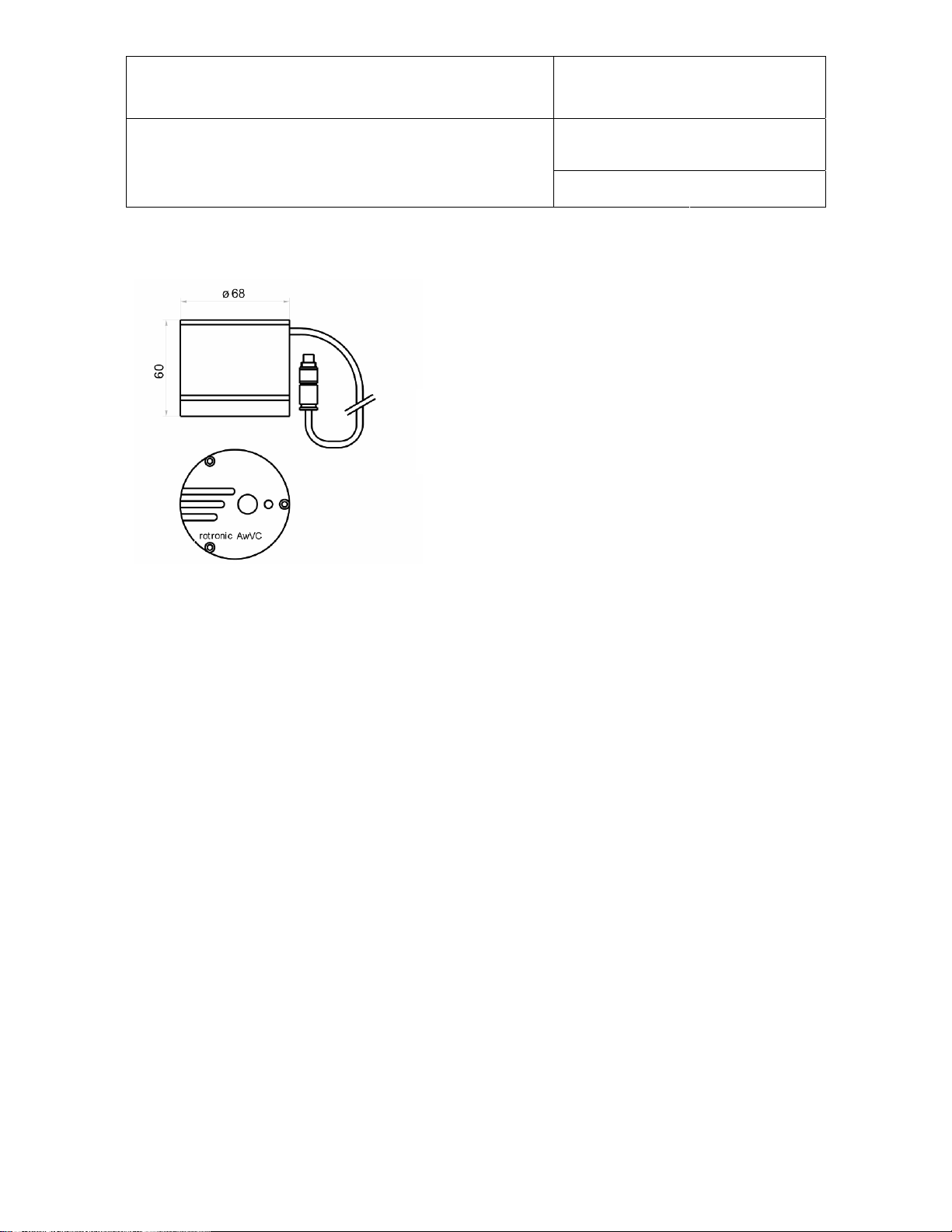
AW-DIO and AwVC-DIO water activity probes
Direct connection to the HygroLab
(probe has a B5 connector)
2.2.2 Analog probes
The HygroLab can be used with one or more analog probes. The corresponding probe input(s) as
well as
using the probe(s). For example, an analog pressure probe may used to provide the local value of
barometric pressure for the computation of parameters such as the wet bulb temperature, mixing
ratio or enthalpy.
Use of analog probes is subject to the following restrictions and limitations:
a. ROTRONIC analog humidity-temperature probes with the standard temperature output signal of
b. Third-party analog probes: single channel probes (one signal), output signal within the range of
c. Resolution is limited by the 10-bit A/D converter
the scale and unit of the analog input signal(s) should be programmed with the HW4 software prior to
– 0.5…2.0 V = -50…200°C: because the HygroLab cannot read a negative voltage signal,
temperature measurement is generally limited to values above freezing.
0 to 2.5 VDC, supply voltage: 9 VDC or less, maximum current consumption: 10 mA.
1)
used for the analog inputs. This converter
provides a theoretical maximum of 1024 counts for an input voltage span of 2.5 VDC. In theory,
this gives a resolution of 2.5 / 1024 = 0.00244 V. In practice, it is not possible to get 100% of the
counts from an A/D converter and the actual resolution should be about 0.0027 V (typical). For
example, if a probe with a temperature signal of 0…1 V = 0…100°C is being used, the signal
resolution will be about 100 x 1 x 0.0027 = 0.27°C.
1) HygroLab 3: 12-bit A/D converter
2.3 Analog outputs (optional)
Analog outputs are optional on the HygroLab 2 and 3. These outputs simply repeat the analog
inputs (if any analog probe is being used). See Connectors - Optional analog output connector.
© 2006; Rotronic AG IN-E-HyLab-V4_11
Page 7

IN-E-HyLab-V4_11
Document code Unit
Rotronic AG
Bassersdorf, Switzerland
HygroLab bench top indicator version 4:
instruction manual
Document title
Instruction Manual
Document Type
Page 7 of 51
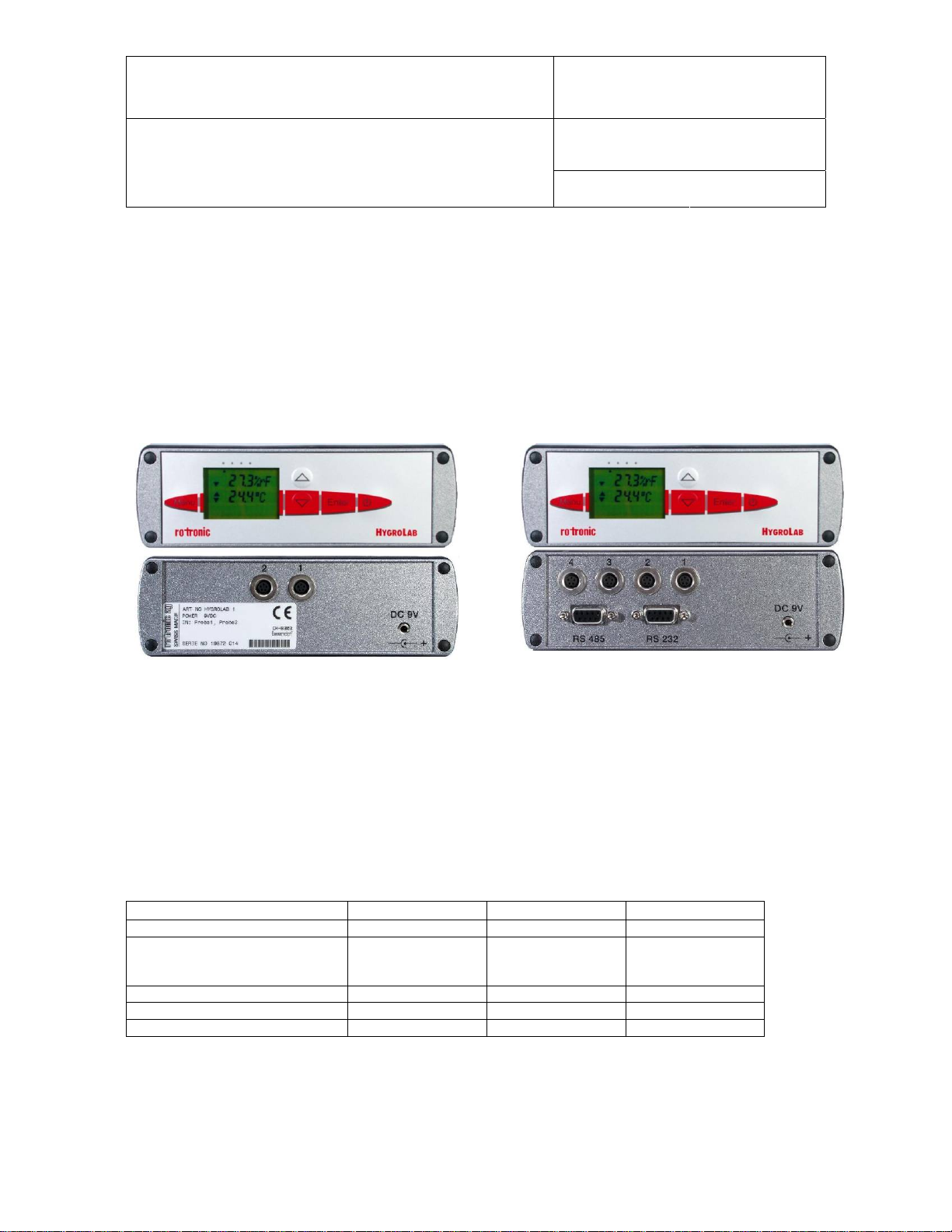
2.4 Serial interface (HygroLab 2 and 3)
Both the HygroLab 2 and 3 have external receptacles (located on the back panel) that provide both
a RS-232 and a RS-485 interface.
Serial interface settings
The HygroLab indicator is compatible with the ROTRONIC HW4 software (version 1.2.2 or higher)
and backward compatible with the ROTRONIC HW3 software. Each software uses a different
communications protocol and different settings regarding the parity, number of data bits and
number of stop bits. When interrogated, the HygroLab automatically recognizes which software and
which protocol is being used. This allows the HygroLab to be used with either HW3 or HW4 without
requiring a manual configuration of the HygroLab serial settings.
When used with HW4, the HygroLab automatically sets its serial interface as follows:
Parity : none
Data bits : 8
Stop bits : 1
When used with HW3, the HygroLab automatically sets its serial interface as follows:
Parity : even
Data bits : 7
Stop bits : 1
Note: the HygroLab will automatically set its serial interface to the above settings when interrogated
by a third-party software that uses the same ASCII commands as HW3 to request data. On models
with the optional Ethernet interface, the internal module must be re-configured as indicated in
document IN-E-TCPIP-Conf_11 (available in PDF format).
IMPORTANT: The HygroLab can be configured by the user with a Baud rate of 57600. The factory
default Baud rate of 19200 is compatible with both HW3 and HW4. The Baud rate of 57600 is
compatible only with HW4.
RS-232 interface
This interface is used to read measurement data, adjust any HygroClip probe connected to the
HygroLab and to configure the HygroFlex. The RS-232 allows direct connection of the HygroLab to
the COM port of a PC (up to 150 m / 490 ft separation)
The HW4 software (version 1.2.2 or higher) should be installed on the PC.
It is also possible to connect the HygroLab 2 or HygroLab 3 to an Ethernet network by using a
device server with a RS-232 port (TCP/IP encapsulation). Depending on the software used to
communicate with the HygroLab, the serial port of the device server should be configured as
indicated below:
© 2006; Rotronic AG IN-E-HyLab-V4_11
Page 8

IN-E-HyLab-V4_11
Document code Unit
Rotronic AG
Bassersdorf, Switzerland
HygroLab bench top indicator version 4:
instruction manual
Document title
Instruction Manual
Document Type
Page 8 of 51
1) PC with HW4 (version 1.2.2 or higher):
Parity : none
Data bits : 8
Stop bits : 1
2) PC with a third-party software using the same ASCII commands as HW3 to request data (see
ASCII communications protocol).
Parity : even
Data bits : 7
Stop bits : 1
RS-485 interface
This interface is used to connect together a number of HygroLab indicators (as well as other
ROTRONIC devices) so as to form a RS-485 multi-drop. This is useful when the number of PC
ports is limited and provides savings on cabling costs. The RS-485 interface has the same
functionality as the RS-232 interface (measurement data, adjustment of HygroClip probes and
device configuration).
In a RS-485 multi-drop, the master is automatically the device that is connected to a COM port,
USB port or network port (Ethernet) of the PC. Any ROTRONIC device that is equipped with both a
RS-232, USB or Ethernet interface and a RS-485 interface can be used as the master. The other
devices in the RS-485 multi-drop are slaves. Any HygroLab 2 or HygroLab 3 indicator can be used
either as a slave or a master, without special configuration other than giving a unique RS-485
address to each device and setting each device to use the same Baud rate.
© 2006; Rotronic AG IN-E-HyLab-V4_11
Page 9
IN-E-HyLab-V4_11
Document code Unit
Rotronic AG
Bassersdorf, Switzerland
HygroLab bench top indicator version 4:
instruction manual
Document title
Instruction Manual
Document Type
Page 9 of 51
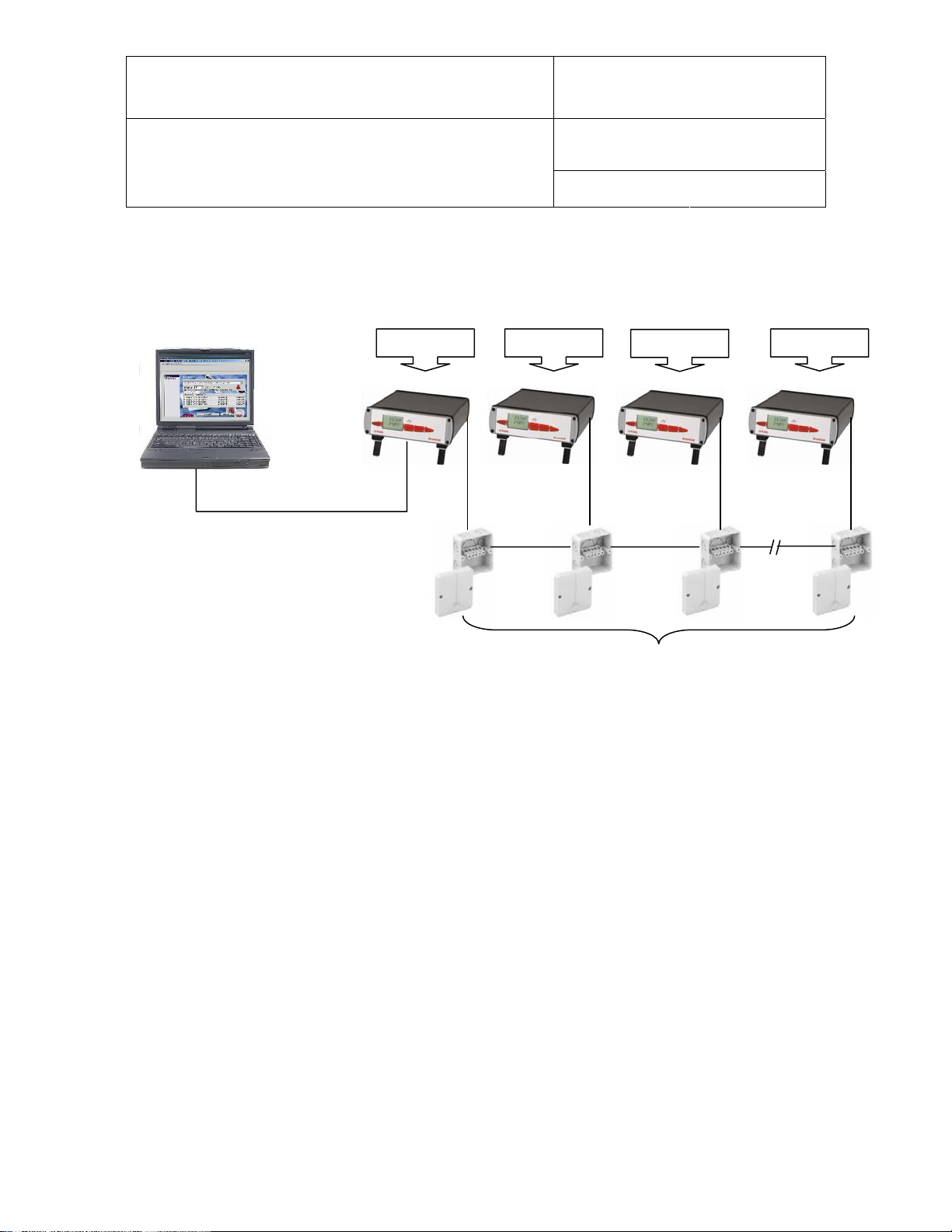
Example of a RS-485 multi-drop
In the following example, the master (address 1) is directly connected to a COM port of the PC
(RS-232). Units 2 to 64 are slaves.
Address 3
RS232: 3 wires
(incl. ground)
max. 150 m
Address 64 Address 2 Address 1
RS485: 2 wires, up to 1000m
Important:
- All devices connected to the same RS-485 multi-drop should use the same baud rate
- Each device within the same RS-485 multi-drop should have a unique address
- In theory, HW4 allows an unlimited number of masters, each with up to 63 slaves. Practical limits
to the total number of devices are set by the PC.
PC with HW4: Except for the distance limitations specific of a RS-232 connection, the above
diagram applies also when the master (for example HygroClip DI interface) is connected to a USB
port or to an Ethernet network.
2.5 Optional Ethernet (TCP/IP) interface (HygroLab 2 and 3)
As an option, both the HygroLab 2 and HygroLab 3 can be ordered with an Ethernet (TCP/IP)
interface in addition to the standard RS-232 and RS-485 serial interface. All different types of
interface offer the same functionality. The HW4 software accepts connection to the PC by means of
an Ethernet network.
© 2006; Rotronic AG IN-E-HyLab-V4_11
Page 10

IN-E-HyLab-V4_11
Document code Unit
Rotronic AG
Bassersdorf, Switzerland
HygroLab bench top indicator version 4:
instruction manual
Document title
Instruction Manual
Document Type
Page 10 of 51
3 Optional configuration and communication software
Depending on the model of HygroLab, the ROTRONIC HW4 software (version 1.2.2 or higher)
offers additional functionality such as:
- Networking (unlimited number of masters, up to 64 units per multi-drop)
- Instrument configuration (unit system, etc.)
- Adjustment of the ROTRONIC HygroClip digital probes
- Data logging to a PC disk file
- Graphic functions (both on and off-line)
- Alarm functions (on-screen display, reports, notification by e-mail, etc.)
HW4 is compatible with Windows XP, NT4 with SP6a or higher. For more details see separate
instruction manual provided with the software.
The HygroLab is backward compatible with the ROTRONIC HW3 software (Windows 98 or NT)
4 How to configure the HygroLab
The HygroLab is configured by the factory as specified when the instrument was ordered. The
configuration can be modified by the user and this requires connecting the HygroLab to a PC with
the ROTRONIC HW4 software installed (version 1.2.2 or higher).
Depending on the model of HygroLab, the following can be configured by the user with Device
Manager in HW4 (where relevant, the factory default is indicated in bold):
- Device name
- RS-485 address [0]
- Device write protection with password [disabled]
- Fixed barometric pressure value used in some psychrometric calculations [1013.25 hPa]
- Dew or frost point calculation below freezing [frost point]
- Language and unit system
- Probe input type (HygroClip probe, analog pressure probe, other analog probe)
- Input name
- Calculated parameter (HygroClip probe only)
- Barometric pressure (fixed value or read from an input) [fixed]
- Alarm threshold (low and high) for humidity, temperature, calculated parameter or other.
- Parameter or custom calculation associated with each analog output and output scale
- Custom calculation (example: difference between two parameters such as dew point)
- Optional display configuration (resolution, trend indicators, parameters to be displayed)
- Keypad: restricted menu access [not restricted]
- Baud rate (serial interface) [19200]
For more details see separate instruction manual provided with the software.
4.1 Internal service connector (HygroLab configuration)
All HygroLab models have an internal RS-232 service connector (MTA) located on the main PCB
(see PCB connections). Cable AC1623 is required to connect the HygroFlex MTA connector to
COM port of a PC.
© 2006; Rotronic AG IN-E-HyLab-V4_11
Page 11

IN-E-HyLab-V4_11
Document code Unit
Rotronic AG
Bassersdorf, Switzerland
HygroLab bench top indicator version 4:
instruction manual
Document title
Use of the MTA service connector is limited to configuring the instrument (unit system, output
range, display, etc.). Both the HygroLab 2 and HygroLab 3 can also be configured via one of the
external digital ports.
Instrument configuration requires a PC with the HW4 software installed. Instructions for configuring
the HygroLab are provided in the software manual.
Instruction Manual
Document Type
Page 11 of 51
4.2 Baud rate compatibility requirements
Depending on the model, devices from ROTRONIC use one of the following Baud rates as the
factory default:
• 57600 bps: HygroLog NT data logger and docking stations
• 19200 bps: HygroPalm and HygroLab indicators, HygroFlex and M33 transmitters, HygroClip
Alarm programmable alarm card, HygroClip DI interface, HygroStat MB Thermo-Hygrostat
The factory default Baud rate of the HygroLab is compatible both with both the ROTRONIC HW4
and HW3 software and is the recommended Baud rate for the HygroLab.
IMPORTANT:
• All devices connected to a RS-485 multi-drop network (master and slaves) must use the
same Baud rate
• Models with the optional Ethernet (TCP/IP) interface: after using HW4 – Device Manager to
change the Baud rate, you should also change the configuration of the internal Ethernet
module to the new Baud rate (see separate HW4 manual).
Devices and internal Ethernet modules with mismatched Baud rate will not communicate together.
• The Baud rate configuration of a ROTRONIC device can be changed with the Device
Manager function (Digital Interface tab) available from within the HW4 software.
• The Baud rate of a Digi Module can be changed only from the module web interface. See
separate document IN-E-TCPIP-Conf_11 (available in PDF format).
4.3 Ethernet local area network
ROTRONIC devices with an Ethernet (TCP/IP) interface presently use an internal module
manufactured by Digi International (Digi Connect ME for a wired connection, Digi Connect WI-ME
for a wireless connection). Both types of module feature a web interface that is used to configure
the module.
IMPORTANT: The TCP/IP settings of models with an Ethernet (TCP/IP) interface should be
configured to be compatible with the local area network. Detailed instructions are provided
separately in document IN-E-TCPIP-Conf_11 (available in PDF format).
Models with an Ethernet (TCP/IP) interface are shipped with a Device Configuration Certificate that
provides information about the factory configuration settings of both the Ethernet module and
device. See example below:
© 2006; Rotronic AG IN-E-HyLab-V4_11
Page 12
IN-E-HyLab-V4_11
Document code Unit
Rotronic AG
Bassersdorf, Switzerland
HygroLab bench top indicator version 4:
instruction manual
Document title
Setting Value
DHCP or Static Address Static
IP Address 192.168.1.1
Subnet Mask 255.255.255.0
Default Gateway 192.168.1.0
TCP Port 2101
MAC Address 00:40:9D:28:2D:2A
Firmware Release (device) 1.4
User Name (web interface) rotronic
Password (web interface) wlan
Serial Port Configuration Profile TCP Sockets
Basic Serial Settings
Baud Rate 57600
Data Bits 8
Parity None
Stop Bits 1
Flow Control None
Instruction Manual
Document Type
Page 12 of 51
4.4 RS-485 multi-drop network (HygroLab 2 and 3)
Both the HygroLab 2 and HygroLab 3 feature a RS-485 connector. When the number of available
PC ports is limited, this connector can be used to connect together up to 64 HygroLab (or other
devices) in a multi-dropped arrangement. In principle, an unlimited number of such networks can
be monitored with the HW4 software, but each RS-485 multi-drop network is limited to 64 devices.
The HygroLab can be used either as a slave or a master, without special configuration. The master
is automatically the device that is directly connected to the PC or LAN by means of a RS-232 port
or TCP/IP port.
RS-485 Address: the RS-485 address is used to identify the individual devices that are connected
to a RS-485 multi-drop and must be unique to each device. This address is part of the HygroLab
communications protocol. The factory default for the RS-485 address is 00. In general, this address
should not be changed manually (see note below). As far as HW4 is concerned, all masters can
share the same RS-485 address. When the HW4 command “Search for RS-485 slaves” is being
used, HW4 automatically changes from 00 to 01 the RS-485 address of any master that has slaves
attached. As a result, all masters end up with the same RS-485 network address (01). In addition,
HW4 automatically changes the RS-485 address of the slaves in each multi-drop from 00 (factory
default) to a unique address ranging from 02 to 64. The same address range (02 to 64) is used
again when there is more than one multi-drop RS485 network.
Notes:
- We recommend using HW4 to give each HygroLab a unique name for easier identification.
- In the situation where an RS-485 network is to be monitored by software other than HW4, you
will have to use HW4 to give each device a unique RS-485 address prior to connecting to the
network.
- If you change an instrument from master to slave, be sure to change the RS address of the
instrument to 00 before establishing the RS-485 connection. Not doing so may prevent HW4
from detecting the instrument. After detecting the instrument, HW4 will automatically change
the RS address to 02 or higher. Please note that HW4 may eventually change the address of
any master with address 00.
© 2006; Rotronic AG IN-E-HyLab-V4_11
Page 13
IN-E-HyLab-V4_11
Document code Unit
Rotronic AG
Bassersdorf, Switzerland
HygroLab bench top indicator version 4:
instruction manual
Document title
Instruction Manual
Document Type
Page 13 of 51
- All devices within a multi-drop should use the same Baud rate. See Baud rate compatibility
requirements.
- Models with Ethernet (TCP/IP) interface: please note that the Baud rate of the HygroLab and
the Baud rate of the internal Ethernet module should be set to the same value.
RS-485 Cable: Using a symmetrical transmission method in combination with low capacity/ low
attenuation twisted pair cables, allows extremely reliable long distance connections. The use of a
high grade shielded cable avoids cross talk between the transmitted signals and also reduces the
potential of external interference. For the RS-485 cable, we recommend using a cable
Cat. 5e ANSI/ TIA /EIA-568-A-5.
In general the RS-485 cable should be shielded and comply with the following specifications:
- Cable capacitance <=300pF/m or 90 pF/ft
- Line impedance 100 Ω ±15 Ω
- Line resistance 140 Ω/km or 225 Ω
- Signal lines Twisted pair
In addition, we recommend terminating each end of the RS-485 cable with a 240 Ohm resistor.
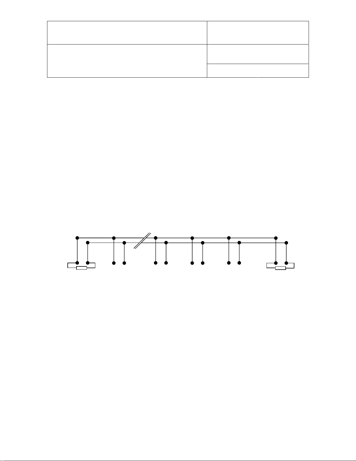
RS485 Network:
240 Ω
Note: all instruments connected to the network should use the same baud rate
Voltage potential issues: The existence of a voltage-potential between instruments that are
interconnected can be a source on concern in large installations, installations with different mains
power supply and in inter-building networking.
As a first measure, the shield of a signal cable should be connected at both ends. In the case of a
data cable, a low-resistance potential equalization cable may also have to be used. This cable
should be run parallel and as near as possible to the data cable, preferably in the same conduit.
The shield of the data cable should under no circumstances be used as equalization cable! The
conductors of the potential equalization cable should ideally be stranded in order to be effective
also in case of high- frequency interference.
Addr. 1 Addr. n
RS485 device connectors
240 Ω
© 2006; Rotronic AG IN-E-HyLab-V4_11
Page 14
IN-E-HyLab-V4_11
Document code Unit
Rotronic AG
Bassersdorf, Switzerland
HygroLab bench top indicator version 4:
instruction manual
Document title
Instruction Manual
Document Type
Page 14 of 51
The following points should also be observed:
• Close the parasitic circuit
• Connect all devices to the potential equalizing cable as often as possible. Electrical
conductors such as machine elements, metal tubes or supporting constructions should be
integrated into the system.
• Protect the potential-equalization cable and connections against corrosion.
• Select the cross-section of the potential equalization cable according to the maximum
equalization current.
If these different measures do not correct the problem, a galvanic separation according to
ISO 9549 may have to be installed. You may also want to consider the use of fiber-optic cables.
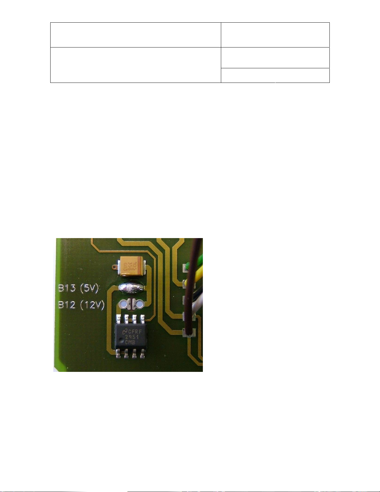
4.5 Selection of the probe supply voltage (main PCB)
Starting with PCB number 66.0739.0302, the probes can be powered with either 5 VDV or directly
from the AC adapter (nominal 12 VDC). The default factory setting is to use the voltage from the
AC adapter. All probes connected to the HygroLab can be supplied with 5 VDC by opening solder
pad B12 and closing solder pad B13 on the main PCB. Depending on the probe model, changing
the probe supply voltage may require the probe to be re-adjusted (please, consult factory).
5 Operation
Connect the AC adapter to the Power connector of the HygroLab and connect a probe
the ON/OFF key. After a brief test and introductory message, the measurements appear on the LC
display. Measurements are updated to the display at the rate of 0.75 sec. x number of digital
probes (HygroClip) connected to the HygroLab.
1) Unless otherwise specified when ordering, all probe inputs are factory programmed to accept a HygroClip
digital probe. Prior to using any analog probe, the corresponding probe input should be re-programmed. This
can be done with the HW4 software after connecting the RS232 port of the HygroLab to a PC (see separate
HW4 manual).
© 2006; Rotronic AG IN-E-HyLab-V4_11
1).
Press on
Page 15
IN-E-HyLab-V4_11
Document code Unit
Rotronic AG
Bassersdorf, Switzerland
HygroLab bench top indicator version 4:
instruction manual
Document title
HygroLab 1 HygroLab 2 and 3
Instruction Manual
Document Type
Page 15 of 51
5.1 Unit system
The unit system can easily be set to Metric or English from the keypad (except HygroLab 1) -see
MENU, SETTINGS. The unit system can also be changed from a PC with the optional HW4
software installed. In that case, connect the HygroLab to a free COM port of the PC using either the
internal service connector (all models) or the RS232 port (HygroLab 2 and 3)
Note: except for the HygroLab 1, the instrument can be configured to display water activity instead
of relative humidity: (instrument configuration with the HW4 software):
1.000 Aw = 100.0 %RH
To change the factory configuration for humidity either use the keypad MENU, SETTINGS (except
HygroLab 1) or use the optional HW4 software installed on a PC and the appropriate connecting
cable: cable AC1623 for all models (see Accessories) or cable type RS232 9pol ST-BU for the
HygroLab 2 and HygroLab 3 (see Connectors for part number).
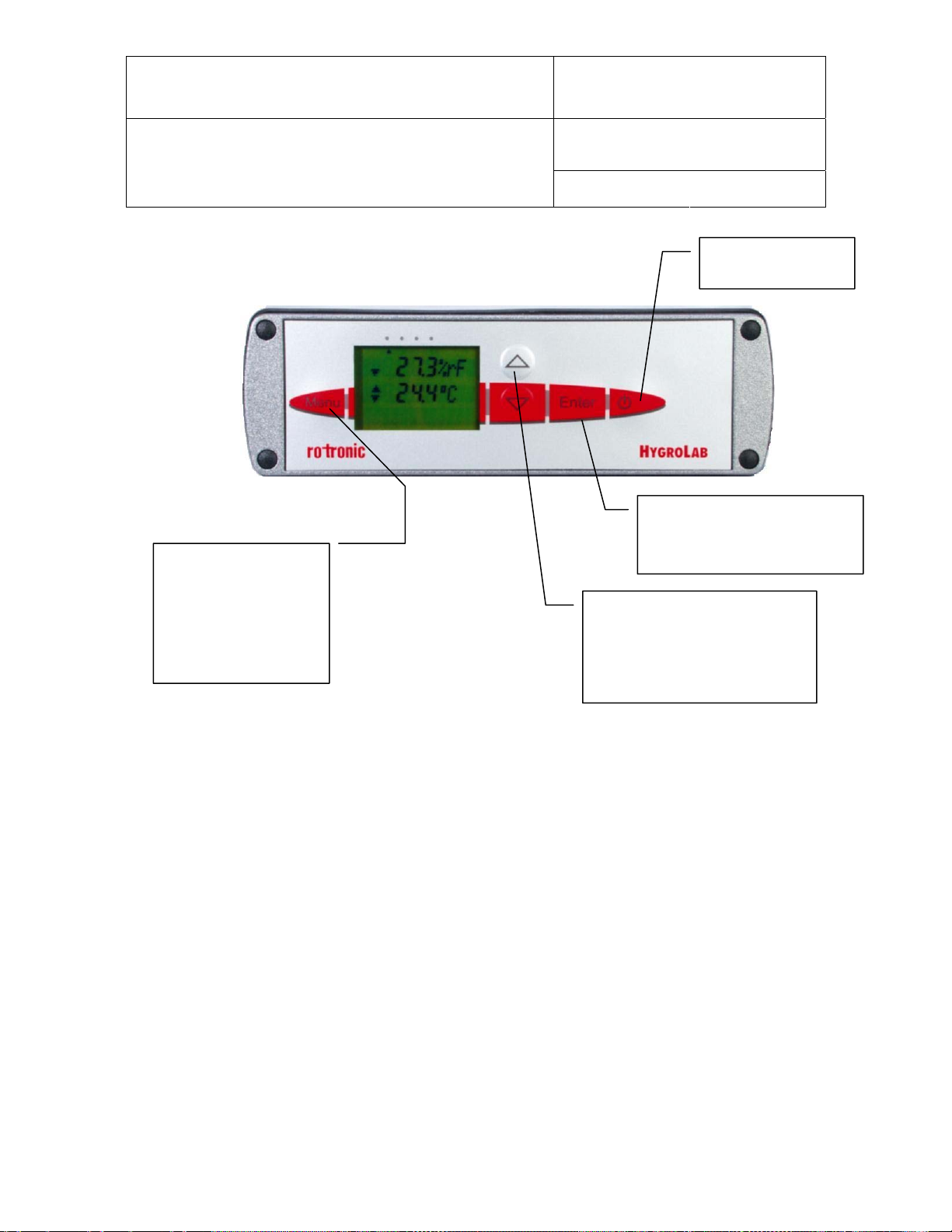
5.2 Display and keypad
The LC display shows which probe input is being displayed (small indicator on top of the display)
and up to 2 parameters measured by the probe, with the associated engineering unit. When
relevant, the message line provides additional information.
(1-4) from left to right
Probe Input
Humidity and Temperature
Calculated Value and Temperature
Calculated Value and Humidity
Parameter or
Engineering
Units
Message Line
© 2006; Rotronic AG IN-E-HyLab-V4_11
Page 16
IN-E-HyLab-V4_11
Document code Unit
Rotronic AG
Bassersdorf, Switzerland
HygroLab bench top indicator version 4:
instruction manual
Document title
MENU : press this key
to activate the functions
menu. The different
menu items appear on
the LCD message line.
Press this key again to
exit the menu
Instruction Manual
Document Type
Page 16 of 51
ON/OFF: turns the
instrument on or off
ENTER: when the menu is
active, press this key to confirm
a selection
UP / DOWN: press one of these
keys to change the probe input
that is being displayed. When the
menu is active, use these keys to
navigate the menu, make a
selection or to change a number
5.3 Probe Input Selection
The display can be switched between probes with the ▼ or ▲ key. The selection is confirmed on
the message line of LC display as well as by an indicator located at the top of the display.
6 Function menu
To access the function menu, press the MENU key. The first menu item appears on the message
line of the LC display. Use the ▼ or ▲ key to navigate the menu. When the desired menu item
appears on the message line of the LC display, press the ENTER key to select. Some menu items
have sub-items. These can be selected with the ▲ or ▼ and ENTER keys. To exit the menu and
return to the normal display mode, press the MENU key. The instrument also returns automatically
to the normal display mode when no key is being pressed for some time (main menu: 10 sec.,
submenu: 30 sec.).
© 2006; Rotronic AG IN-E-HyLab-V4_11
Page 17

IN-E-HyLab-V4_11
Document code Unit
Rotronic AG
Bassersdorf, Switzerland
HygroLab bench top indicator version 4:
instruction manual
Document title
Instruction Manual
Document Type
Page 17 of 51
6.1 CALCULATE (HygroLab 2 and 3)
Definition
This function is used to select or view the humidity parameter that is calculated by the instrument.
The calculated parameter is selected individually for each probe connected to the instrument
Prior to entering this function, select on the display the probe to program.
1) Does not apply to third-party analog probes.
The unit system (Metric or English) can be changed with the keypad (see Functions, Settings) or
with the optional HW4 software, when the HygroLab is connected to a PC.
Selections
Parameter Metric English Lab 1 Lab 2 Lab 3
Dew Point / Frost Point 1)
°C °F
N/A
x x
1)
.
Wet Bulb Temperature 2)
°C °F
Enthalpy 2) J/g BTU/lb N/A
Vapor Concentration g/m3 gr/cuft N/A
Specific Humidity 2) g/kg gr/lb N/A
Mixing Ratio 2) g/kg gr/lb N/A
Vapor Concentration
at Saturation
Partial Pressure
of Water Vapor
Saturation Pressure
of Water Vapor
3
g/m
gr/cuft N/A
hPa PSI or In Hg N/A
hPa PSI or In Hg N/A
N/A
x x
X X
X X
X X
X X
X X
X X
X X
1) The standard factory setting is frost point for values below freezing. This setting can be changed to dew
point with the optional HW4 software
2)
Calculation of this parameter requires barometric pressure as an input. The fixed value used for barometric
pressure can be changed either directly from the keypad - see MENU, SETTINGS - or with the optional HW4
software (all models). The HygroLab 2 or 3 can also be configured to accept the input from an analog
pressure probe (variable pressure value).
© 2006; Rotronic AG IN-E-HyLab-V4_11
Page 18

IN-E-HyLab-V4_11
Document code Unit
Rotronic AG
Bassersdorf, Switzerland
HygroLab bench top indicator version 4:
instruction manual
Document title
Instruction Manual
Document Type
Page 18 of 51
6.2 MODE (HygroLab 3)
Definition
This function is used to set the operating mode of the HygroLab 3
Selections
Standard : normal operating mode (relative humidity, temperature, dew point, etc.)
Q AwQuick : water activity measurement with the AwQuick algorithm for measurements in
typically 5 minutes.
E AwE : conventional water activity measurement with automatic detection of equilibrium
conditions.
Note:
The operating mode selection applies to all probe inputs. Upon start up, the HygroLab 3
remembers in which mode it was before being turned off
● Standard Mode:
This mode is the default mode of the HygroLab 3. Upon powering the HygroLab 3, the instrument
automatically defaults to the standard mode.
In the standard mode, the HygroLab 3 displays the humidity and temperature measured by the
selected probe. Trend indicators appear one minute after powering up the instrument (▲ or ▼
arrow to the left of the water activity and temperature values). These indicators are used to detect
equilibrium conditions as required for example during probe calibration. The probe is at equilibrium
when both the up and down arrow are displayed at the same time.
● AwE mode:
This mode is essentially the same as the standard mode with the difference that the HygroLab 3
automatically detects equilibrium conditions and ends the measurement at that time by freezing the
display.
● AwQuick mode:
This mode accelerates the measurement of water activity and provides a result in typically 5
minutes. When temperature conditions are stable (both at the product and probe), the
measurement obtained with the AwQuick mode is generally within ± 0.005 aw of the measurement
that would be obtained by waiting for full equilibration of the product and probe.
Depending on the mode that was selected, proceed as follows
© 2006; Rotronic AG IN-E-HyLab-V4_11
Page 19

IN-E-HyLab-V4_11
Document code Unit
Rotronic AG
Bassersdorf, Switzerland
HygroLab bench top indicator version 4:
instruction manual
Document title
a) Standard Mode:
No further action is required after selecting this mode. Simply proceed with the measurements.
b) AwE Mode:
Upon selecting this mode, the HygroLab 3 displays the following:
0. 0 0 0
1
Instruction Manual
Document Type
Page 19 of 51
E H S [ A w / m i n ]
Use the ▼ or ▲ arrow to set the definition of stable humidity. In the above example, the HygroLab
will consider humidity to be at equilibrium when the rate of change of the humidity signal is less
than 0.0001 Aw per minute. Default value: 0.0001 Aw / min
Press the ENTER key to record and confirm this setting. The display now shows the following:
E T S [
Use the UP or DOWN arrow to set the definition of stable temperature. In the above example, the
HygroLab will consider temperature to be at equilibrium when the rate of change of the temperature
signal is less than 0.01 °C per minute. Default value: 0.01 °C / min
Press the ENTER key to record and confirm this setting. The AwE mode is now active.
When ready to measure, press the ENTER key to access and start the AwE mode. Press the
ENTER key again to stop the AwE mode at any time and return to the Standard mode.
Notes:
When the HygroLab 3 is in the AwE mode, pressing the ENTER key automatically starts the
AwE mode, unless the MENU key was pressed immediately before pressing the ENTER key.
The ON / OFF key is inoperative in the AwE mode. You must stop the AwE mode in order to be
able to turn the power of with the red ON/OFF key.
For instructions on using the AwE mode, see Water Activity Measurement.
0. 0 1
°
C/min]
© 2006; Rotronic AG IN-E-HyLab-V4_11
Page 20

IN-E-HyLab-V4_11
Document code Unit
Rotronic AG
Bassersdorf, Switzerland
HygroLab bench top indicator version 4:
instruction manual
Document title
c) AwQuick Mode:
Upon selecting this mode, the HygroLab 3 displays the following:
4
Instruction Manual
Document Type
Page 20 of 51
Q D w e l l [ m i n ]
Use the ▼ or ▲ arrow to set the dwell time. In the above example, the HygroLab 3 will wait 4
minutes before processing the humidity data with the AwQuick algorithm.
Default value: 4 min (recommended value)
Press the ENTER key to record and confirm this setting. The display now shows the following:
Q T S [
Use the UP or DOWN arrow to set the definition of stable temperature. In the above example, the
HygroLab will consider temperature to be stable when the rate of change of the temperature signal
is less than 0.01 °C per minute.
Default value: 0.01 °C / min
Press the ENTER key to record and confirm this setting. The AwQuick mode is now active.
When ready to measure, press the ENTER key to access and start the AwQuick mode. Press the
ENTER key again to stop the AwQuick mode at any time and return to the Standard mode.
Notes:
When the HygroLab 3 is in the AwQuick mode, pressing the ENTER key automatically starts
the AwQuick mode, unless the MENU key was pressed immediately before pressing the
ENTER key.
The ON / OFF key is inoperative in the AwQuick mode. You must stop the AwQuick mode in
order to be able to turn the power of with the red ON/OFF key.
For instructions on using the AwQuick mode, see Water Activity Measurement.
© 2006; Rotronic AG IN-E-HyLab-V4_11
0. 0 1
°
C/min]
Page 21

IN-E-HyLab-V4_11
Document code Unit
Rotronic AG
Bassersdorf, Switzerland
HygroLab bench top indicator version 4:
instruction manual
Document title
Instruction Manual
Document Type
Page 21 of 51
6.3 DISPLAY (HygroLab 2 and 3)
Definition
This function is used to select which parameters the instrument displays. The display mode is
specified globally for all probes connected to the instrument.
Selections
- Measurement
Relative humidity (in %RH or as water activity: Aw) and temperature or the parameter
measured by any third party probe connected to the instrument.
- Calculated + Temperature
Calculated parameter (as selected under CALCULATE) and temperature. This selection is
not available with third-party probes.
- Calculated + Humidity
Calculated parameter (as selected under CALCULATE) and relative humidity. This
selection is not available with third-party probes.
- User Calc
User defined calculation such as the difference between temperature and dew point of any
probe. The display shows only the calculated value. See the separate HW4 manual for
instructions on how to program the HygroLab 2 or 3 to compute a user specified
parameter.
6.4 ADJUST M.PT
Definition
The Adjust M.PT function permits the full calibration of any ROTRONIC HygroClip digital probe
against a known reference environment. This function is designed to permit calibration at 2
temperature values and at up to 4 relative humidity values.
Selections
The Adjust M.PT function offers the following choices (use the UP and DOWN keys):
RHS: Humidity calibration using the ROTRONIC Humidity Standards
Humidity: Humidity calibration using any suitable reference environment
Temperature: Temperature calibration using any suitable reference environment
1)
For humidity calibration, ROTRONIC offers convenient, certified humidity standards to generate
known humidity values (for details, see Humidity Calibration).
© 2006; Rotronic AG IN-E-HyLab-V4_11
1)
Page 22

IN-E-HyLab-V4_11
Document code Unit
Rotronic AG
Bassersdorf, Switzerland
HygroLab bench top indicator version 4:
instruction manual
Document title
Instruction Manual
Document Type
Page 22 of 51
Procedure
When more than one probe is connected to the instrument, select the probe to be calibrated prior
to entering the function (this is the same as the probe that was last displayed).
Regarding the Adjust M.PT function, it is important to observe the following rules:
a) Always calibrate temperature first (if temperature needs to be calibrated)
b) When calibrating temperature (2 points), always calibrate at the low value first. The
instrument is programmed to use the low temperature value to compute the offset and the
high temperature value to compute the gain.
T-low < 40 °C (104°F) : used to compute the calibration offset
T-high ≥ 40 °C (104 °F) : used to compute the calibration gain
For best accuracy, we recommend using a T-low value close to 20°C (68°F).
c) When calibrating relative humidity (2, 3 or 4 points) with the ROTRONIC humidity
standards, always follow the sequence 35 %RH, 80 %RH, 10 %RH or 5 %RH, 0 %RH).
When using a reference other than the ROTRONIC humidity standards, use reference
conditions that are within the following brackets and observe the sequence:
>25 %RH…≤55 %RH
>55 %RH
1)
: used to compute the calibration gain
>1 %RH…≤25 %RH : sensor linearity adjustment
≤ 1 %RH : sensor linearity adjustment
The HygroLab is programmed to automatically recognize these brackets.
1) For best accuracy, we recommend using values close to 35 %RH and 80 %RH
When the probe is at equilibrium with the reference environment, activate the Adjust M.PT function
and make the appropriate selections:
a) RHS: press the ENTER key to select this item. The LC display shows the value read by the
probe at the time the ENTER key was pressed. The letters “RHS” are displayed on the
message line. Use the ▼ or ▲ key to change the humidity value to match the mean value
(at 23°C) written on the certificate supplied with the standard. For a faster change, keep
the key pressed down. Press the ENTER key when done.
Note: in the RHS mode, the software automatically compensates for the effect of
temperature on the humidity standard. No additional correction is required.
b) Humidity or Temperature: press the ENTER key to select. The LC display shows the
value read by the probe at the time the ENTER key was pressed. The word “humidity” or
“Temperature” is shown on the message line. Use the ▼ or ▲ key to change the humidity
or temperature value to match the value of the reference environment. For a faster change,
keep the key pressed down. Press the ENTER key when done.
© 2006; Rotronic AG IN-E-HyLab-V4_11
1)
: used to compute the calibration offset
Page 23

IN-E-HyLab-V4_11
Document code Unit
Rotronic AG
Bassersdorf, Switzerland
HygroLab bench top indicator version 4:
instruction manual
Document title
After pressing the ENTER key, the message “sure?” should appear on the LC display. Press
ENTER to confirm. Next, the LC display will confirm that the probe adjustment has been
successfully completed. At that time, press ENTER to exit or MENU to return to the function Adjust
M.PT and do another calibration point.
Instruction Manual
Document Type
Page 23 of 51
Carry on in the same manner for each calibration point, following the sequence described above.
Note: you can exit the function at any time (without calibrating the probe) by pressing the MENU
key.
6.5 ADJUST 1PT
Definition
The Adjust 1PT function permits to do a 1-point adjustment (temperature or humidity) of any
ROTRONIC HygroClip digital probe against a known reference environment. This function is limited
to a simple offset adjustment that is applied across the entire measuring range.
Warning
1-point adjustment can improve accuracy over a narrow range of conditions and may also be
detrimental to accuracy at other conditions.
Selections
The Adjust 1PT function offers the following choices (use the UP and DOWN keys):
RHS: Humidity calibration using the ROTRONIC Humidity Standards
Humidity: Humidity calibration using any suitable reference environment
Temperature: Temperature calibration using any suitable reference environment
1) For humidity calibration, ROTRONIC offers convenient, certified humidity standards that generate known
humidity values (for more details, see Humidity Calibration).
Procedure
When more than one probe is connected to the instrument, select the probe to be calibrated prior
to entering the function (this is the same as the probe that was last displayed).
When the probe is at equilibrium
and make the appropriate selections:
: a 1-point adjustment is no substitute for a full calibration (2 or more points). Doing a
1)
with the reference environment, activate the Adjust 1PT function
a) RHS: press the ENTER key to select this item. The LC display shows the value read by the
probe at the time the ENTER key was pressed. The letters “RHS” are displayed on the
message line. Use the ▼ or ▲ key to change the humidity value to match the mean value
(at 23°C) written on the certificate supplied with the standard. For a faster change, keep
the key pressed down. Press the ENTER key when done.
Note: in the RHS mode, the software automatically compensates for the effect of
temperature on the humidity standard. No additional correction is required.
© 2006; Rotronic AG IN-E-HyLab-V4_11
Page 24

IN-E-HyLab-V4_11
Document code Unit
Rotronic AG
Bassersdorf, Switzerland
HygroLab bench top indicator version 4:
instruction manual
Document title
b) Humidity or Temperature
1
: press the ENTER key to select. The LC display shows the
Instruction Manual
Document Type
Page 24 of 51
value read by the probe at the time the ENTER key was pressed. The word “humidity” or
“Temperature” is shown on the message line. Use the ▼ or ▲ key to change the humidity
or temperature value to the value of the reference environment. For a faster change, keep
the key pressed down. Press the ENTER key when done.
1
1-point temperature adjustment: limited by the firmware to -20…< 40°C (-4…<104°F)
After pressing the ENTER key, the message “sure?” should appear on the LC display. Press
ENTER to confirm. Next, the LC display will confirm that the probe adjustment has been
successfully completed. At that time, press ENTER to exit.
Note: you can exit the function at any time (without calibrating the probe) by pressing the MENU
key.
6.6 ADJUST REF
Definition
Note: this function is not available with the HygroLab 1
When two or more ROTRONIC HygroClip digital probes are connected to the HygroLab, the Adjust
REF function uses probe #1 as a reference to do a 1-point adjustment (both humidity and
temperature) of all the other probes simultaneously.
Warning
point adjustment can improve accuracy over a narrow range of conditions and may also be
detrimental to accuracy at other conditions.
Procedure
Expose all probes to the same stable environment. Ventilation of the probes is highly
recommended. Observe the readings from all probes for complete equilibration with the reference
environment.
Press the ENTER key to enter the function. The display asks you to wait for a short time and then
shows the temperature and humidity read by the reference probe at the time the ENTER key was
pressed. Note that these values are not updated to the display as long as the function is active.
The message line of the display shows REF = Probe 1, indicating that probe #1 is the reference
(this cannot be changed).
Press the ENTER key to accept. After pressing the ENTER key, the message “sure?” should
appear on the LC display. Press ENTER to confirm. Next, the LC display will confirm that the probe
adjustment has been successfully completed. At that time, press ENTER to exit. Note: you can exit
the function at any time (without calibrating the probe) by pressing the MENU key.
: a 1-point adjustment is no substitute for a full calibration (2 or more points). Doing a 1-
© 2006; Rotronic AG IN-E-HyLab-V4_11
Page 25

IN-E-HyLab-V4_11
Document code Unit
Rotronic AG
Bassersdorf, Switzerland
HygroLab bench top indicator version 4:
instruction manual
Document title
Instruction Manual
Document Type
Page 25 of 51
6.7 PROBE
Definition
This function displays the version number and serial number of any ROTRONIC HygroClip digital
probe connected to the instrument.
Procedure
Prior to entering the function, select the probe to be displayed (this is the same as the probe that
was last displayed).
When entering the function, the version number of the probe is displayed first. Use the ▼ or ▲ key
to display the serial number of the probe.
6.8 SETTINGS
Definition
This function is used to do the following:
• Turn the trend indicators on or off
• change the symbol used for relative humidity or display humidity as Water Activity (aw)
• adjust the fixed value of barometric pressure used in some psychrometric computations
(except HygroLab 1)
• select between the Metric or English unit system
Procedure
Trend: use the ▼ or ▲ key to enable or disable the trend indicators.
The trend of humidity and temperature is shown on the display by an arrow (up or down) to the left
of the measured value. Both arrows are shown to indicate stable conditions. Stable conditions are
defined as rate of change of less than 0.02 %RH / min or °C / min.
Signal stability is first evaluated after 60 seconds into the measurement and is updated every 30
seconds.
Note: when the trend indicator is enabled, the symbol for the calculated parameter (e.g. Dp for dew
point) is no longer displayed to the left of the numerical value.
Humi Unit: use the ▼ or ▲ key to change the symbol used for relative humidity (depends on
country and language) or to display humidity as water activity.
Press. Const. (except HygroLab 1) : use the DOWN arrow key to select the digit to be changed.
Use the UP arrow key to change the value of the digit.
Units: use the ▼ or ▲ arrow key to toggle between Metric and English.
© 2006; Rotronic AG IN-E-HyLab-V4_11
Page 26

IN-E-HyLab-V4_11
Document code Unit
Rotronic AG
Bassersdorf, Switzerland
HygroLab bench top indicator version 4:
instruction manual
Document title
Instruction Manual
Document Type
Page 26 of 51
6.9 SYS STATUS
Definition
This function displays the software version of the instrument, the RS232 configuration * (baud rate,
parity, bits and stop bit), the network address *, any user defined description for the instrument *
and the serial number of the instrument.
This information is for display only. Some parameters such as the network address can be
changed with the HW4 software, after connecting the instrument to a PC.
* except HygroLab 1
Procedure
When entering the function, the software version number is displayed first. Use the ▼ or ▲ key to
display the other data.
7 Error and status messages
The following is a list of coded messages (101, etc.) that the HygroLab may show on the bottom
line of the LC display or via RS232 / RS485.
Errors:
101
102
103
104
105
106
107
108
110
111
Warnings:
120
121
Status:
130
checksum error The checksum test did not pass during RS-communication.
bad command An unknown command was received
disallowed
command
unknown probe
input
argument error
HygroClip
A command was received that is reserved for production and
service
Reference was made to a non-existing analog or digital probe
input
Error in the number of the arguments in the command or in
the value of one of the arguments
The HygroClip probe does not answer or is not connected
communication error
The difference between the probe reading and the calibration
calibration error
point is larger than the maximum allowed by the INI
command.
calibration error
(overflow)
unknown reference
probe
Temperature error
Internal probe error (or the difference between the probe
reading and the calibration value is too large)
The reference probe is not connected or the reference probe
input does not exist
During humidity calibration, temperature should be within the
limits of 0 and 80°C (32 and 176°F)
no adjustment Calibration
No HygroClip probe
is connected
the probe was
Calibration
adjusted
© 2006; Rotronic AG IN-E-HyLab-V4_11
Page 27

IN-E-HyLab-V4_11
Document code Unit
Rotronic AG
Bassersdorf, Switzerland
HygroLab bench top indicator version 4:
instruction manual
Document title
Instruction Manual
Document Type
Page 27 of 51
8 Connectors
Internal service connector (HygroLab 1)
Open the instrument housing to access the service connector. This 3-pin connector is located on
the printed circuit board as shown below:
Probe input connectors
RS232 / RS485 (HygroLab 2 and 3)
Service connector
use cable # AC1623 to connect
to the COM port of a PC
RS232 connector (9-pin Sub D)
Pin # Function
2 TX
3 RX
5 GND
RS485 connector (9-pin Sub D)
Pin # Function
1 RI +
5 GND (normally not used)
9 RI -
© 2006; Rotronic AG IN-E-HyLab-V4_11
Page 28

IN-E-HyLab-V4_11
r
Document code Unit
Rotronic AG
Bassersdorf, Switzerland
HygroLab bench top indicator version 4:
instruction manual
Document title
Instruction Manual
Document Type
Page 28 of 51
Optional analog output connector (HygroLab 2 and 3)
If any analog probe is being used, this connector simply repeats the analog probe input signals.
Optional
Analog Output
DB25F Connecto
13
Pin # Function
1 Probe 1 – Analog 1
2 Probe 1 – Analog 2
3 GND
4 Probe 2 – Analog 1
5 Probe 2 – Analog 2
6 GND
7 Probe 3 – Analog 1
8 Probe 3 – Analog 2
9 GND
10 Probe 4 – Analog 1
11 Probe 4 – Analog 2
12 GND
1
Optional RJ-45 (Ethernet) connector – HygroLab 2 and 3
Ethernet
9 Environmental limits
The HygroLab can operate in the temperature range of –10...55°C (14…131°F) and should not be
exposed to condensing humidity.
The operating limits at the probe depend on the probe model and are specified separately for each
probe.
© 2006; Rotronic AG IN-E-HyLab-V4_11
Page 29

IN-E-HyLab-V4_11
Document code Unit
Rotronic AG
Bassersdorf, Switzerland
HygroLab bench top indicator version 4:
instruction manual
Document title
Instruction Manual
Document Type
Page 29 of 51
10 Maintenance of the ROTRONIC probes
Cleaning or replacing the dust filter
Most ROTRONIC probes come with one of the following types of dust filter: (a) protective
metal base with a removable filter cartridge or (b) plastic slotted cap with built-in (not
removable) filter element.
Depending on the conditions of measurement, the filter should be checked from time to time. If
the probe has a removable filter cartridge, this can be easily removed for cleaning.
If the probe has a plastic slotted cap with a built-in filter element, cleaning should be done
without
other strong chemicals. Either brush the filter or use a little bit of clean water.
Corroded, discolored or clogged filters should be replaced. If the probe has a removable
cartridge, simply replace the cartridge (leave the metal base on the probe).
If the probe has a plastic slotted cap with built-in filter element follow these instructions:
1) Unscrew the filter from the probe and pull it straight away, in the alignment of the probe, so
as not the catch the humidity and temperature sensors.
2) Before putting on a new dust filter, check the alignment of both sensors with the probe. The
wires that connect the sensors to the probe are very thin and bend easily. If necessary, correct
the alignment by tapping the sensor very gently
rod. Do not use sharp pliers or tweezers as this could puncture the sensor and do not pull
hard on the sensor.
removing the filter from the probe. In that case, do not use detergents, solvents or
Periodic calibration check
Long term stability of the ROTRONIC Hygromer humidity sensor is typically better than 1
%RH per year. For maximum accuracy, calibration of the probe should be verified every 6 to
12 months. Applications where the probe is exposed to significant pollution may require more
frequent verifications.
Both the Pt 100 RTD temperature sensor and associated electronics are very stable and
should not require any calibration after the initial factory adjustment.
For routine calibration checks, the probe should be verified at one or two values of humidity.
For more details, see Probe calibration basics and Functions – ADJUST M.PT.
with a smooth object such as a small plastic
© 2006; Rotronic AG IN-E-HyLab-V4_11
Page 30

IN-E-HyLab-V4_11
Document code Unit
Rotronic AG
Bassersdorf, Switzerland
HygroLab bench top indicator version 4:
instruction manual
Document title
Instruction Manual
Document Type
Page 30 of 51
11 Specifications
Power supply AC Adapter 12 VDC regulated,
100 or 300 mA
DC(+) Tip
Operating limits at electronics 0…99 %RH (non condensing)
-10...55°C (14...131°F)
Measured parameters
relative humidity indication range 0.0…100.0 %RH
temperature
barometric pressure 3) indication range
Calculated parameters
dew / frost point
wet bulb temperature
enthalpy
6)
indication range -99.9…9999 J/g or BTU/lb
vapor concentration indication range 0.000…9999 g/m3 or gr/cuft
specific Humidity
mixing ratio
6)
indication range 0.000…9999 g/kg or gr/lb
2)
indication range
2) 4)
5)
6)
indication range -99.9…999.9 °C / °F
6)
indication range 0.0…100.0 °C / 32.0…212.0 °F
indication range 0.000…9999 g/kg or gr/lb
-99.9…999.9 °C or °F
0.000…9999 hPa / PSI / In Hg
vapor concentration at saturation indication range 0.000…9999 g/m3 or gr/cuft
part. pressure of water vapor indication range 0.000…9999 hPa / PSI / In Hg
sat. pressure of water vapor indication range 0.000…9999 hPa / PSI / In Hg
Number of probe inputs HygroLab 1 2
HygroLab 2+3 4
Probe type
7)
All models ROTRONIC HygroClip digital probe
All models ROTRONIC analog probe
HygroLab 2+3 Third-party analog probe
A/D resolution (analog probes) HygroLab 1+2 10-bit
A/D resolution (analog probes) HygroLab 3 12-bit
Display Alphanumerical LC display
Serial output (except HygroLab 1) RS 232 / RS485
Optional Ethernet interface HygroLab 2+3 TCP/IP
Housing material Aluminum
Housing dimensions 220 x 170 x 55 mm (8.66 x 6.69 x 2.16”)
Weight 1.0 kg (2.2 lb)
1) HygroLab with optional Ethernet module requires : AC Adapter 12 VDC, 300 mA
2) Specify engineering units when ordering (can be changed by user with the optional HW4 software). See
separate probe specifications regarding the different range limits
3) Not available with HygroLab 1
4) Not available with HygroLab 1. The accuracy of the computed parameter is limited by the accuracy of the
measured parameters on which it is based
5) The standard factory setting is frost point for values below freezing. This setting can be changed to dew
point with the optional HW4 software
6) A fixed pressure value is used for the computations of this parameter. The fixed pressure value can be
changed by the user either from the keypad or with the optional HW4 software. The HygroLab 2 and 3 can
also be configured with the HW4 software to accept the input from a pressure probe (variable pressure
value)
1)
8)
8)
9)
© 2006; Rotronic AG IN-E-HyLab-V4_11
Page 31

IN-E-HyLab-V4_11
Document code Unit
Rotronic AG
Bassersdorf, Switzerland
HygroLab bench top indicator version 4:
instruction manual
Document title
Instruction Manual
Document Type
Page 31 of 51
7) Accuracy, repeatability and operating limits are specified separately for each model of probe
8) ROTRONIC analog probes: because the HygroLab cannot read a negative input voltage, temperature
measurement with probes having a standard output is generally limited to values above freezing. Thirdparty probe (pressure or other): linearized voltage output signal within the range of 0...2.5 VDC, supply
voltage 5 to 12 VDC, 10 mA max.
9) RS-485 network: requires the first instrument to be connected to the RS-232 COM port of a PC.
Compatibility with the ROTRONIC HW3 software requires a baud rate of 19200.
12 Practical advice for measuring humidity
The most common source of error when measuring relative humidity is a difference between the
temperature of the probe and the temperature of the environment. At a humidity condition of 50
%RH, a temperature difference of 1°C (1.8 °F) typically results in an error of 3 %RH on relative
humidity.
When using a humidity probe with an indicator, it is good practice to monitor the display for
temperature stability. The probe should be given sufficient time to equilibrate with the
environment to be measured. The larger the initial temperature difference between the probe
and the environment to be measured, the more time temperature equilibration requires. This
time can be shortened, and errors avoided, by using the probe configuration that fits best for
your application.
In extreme situations, condensation may occur on the sensors when the probe is colder than the
environment. As long as the humidity / temperature limits of the humidity sensor are not
exceeded, condensation does not alter the calibration of the sensor. However, the sensor has to
dry out before it can provide a valid measurement.
Non-moving air is an excellent insulator. When there is no air movement, surprising differences in
temperature and humidity can noted over short distances. Air movement at the probe generally
results in measurements that are both faster and more accurate.
13 Probe calibration basics
The following choices are available to calibrate the HygroClip probe(s) used with the HygroLab:
a) Calibration using the HygroLab display and keypad (see Functions).
b) Calibration using a PC with the optional HW4 software (see separate instructions for the
HW4 software) – This choice is available only with the HygroLab 2 and 3, after connecting
the HygroLab to the COM port of the PC.
c) Calibration of the probe alone (removed from the HygroLab), using a PC with the HW3
software and the MOK-WIN or T7-WIN calibration cable (see separate instructions for the
HW3 software).
Note: the HygroLab itself should not require any field calibration.
13.1 Temperature calibration
Note: the stability of the Pt100 RTD sensor used to measure temperature is such that
temperature calibration in the field is seldom required.
In order to be able to correctly evaluate the accuracy of the temperature measurements
provided by the probe, you should be able to meet the following requirements:
© 2006; Rotronic AG IN-E-HyLab-V4_11
Page 32

IN-E-HyLab-V4_11
Document code Unit
Rotronic AG
Bassersdorf, Switzerland
HygroLab bench top indicator version 4:
instruction manual
Document title
a) Both the probe and a reference thermometer should be ventilated with the same stream of
air. Any dust filter used to protect the sensors should be carefully removed from the probe.
If the probe has a protective slotted cap, this may be left on the probe.
b) Air velocity at the sensor should be within the limits of 200 to 500 feet/minute (1 to 2.5
meters/second). Any comparison between two instruments at a velocity under 200
feet/minute may not be valid. Air velocity above 500 feet/minute may damage the
unprotected humidity sensor.
c) The temperature of the air stream should be practically constant.
If you cannot meet the above requirements, you should not attempt to calibrate temperature.
Instruction Manual
Document Type
Page 32 of 51
13.2 Humidity calibration
ROTRONIC provides easy-to-use, certified humidity standards for customers who do not have
access to a humidity generator. To use these standards, you will need a calibration device that
is suitable for your probe.
Calibration device
The calibration device is a small airtight container that fits on the probe and seals around the
humidity sensor. During calibration, a known reference humidity is produced inside the
calibration device by means of a humidity standard (usually an aqueous salt solution). To find
out which model of calibration device is suitable for your probe, please consult the probe
documentation.
Certified humidity standards
The ROTRONIC certified standards are available in boxes of 5 glass ampoules of the same
value, which can be stored indefinitely. Standards in the range of 5 to 95 %RH are nonsaturated aqueous salt solutions that are precisely titrated at our factory for the right
concentration. The 0 %RH humidity standard is made of small granules of a highly porous
ceramic that have been dried at a high temperature. A Material Safety Data Sheet is available
for each standard. Since most standards are a salt solution, parts which have come in contact
with the liquid should be cleaned after each use.
Each box of standards comes with a certificate that provides statistical information on the
manufacturing batch of the standard. Information on the effect of temperature on each
standard is provided on the cover of each box of standard. When calibrating either with the
HygroLab or with the HW4 software, the effect of temperature on the standards is
compensated by the software and no further correction is required. The value of the standards
is not affected by altitude.
© 2006; Rotronic AG IN-E-HyLab-V4_11
Page 33

IN-E-HyLab-V4_11
Document code Unit
Rotronic AG
Bassersdorf, Switzerland
HygroLab bench top indicator version 4:
instruction manual
Document title
Instruction Manual
Document Type
Page 33 of 51
Instructions for using the standards
• Install the calibration device on the probe so that the receptacle (or solution holder) is
under the probe. Check for a tight fit and remove the receptacle from the calibration device.
• Place one fiber disc (each box of standards includes 5 discs) in the receptacle of the
calibration device. The purpose of this disc is to prevent accidental spilling of the solution
inside the calibration device or on the humidity sensor.
• Tap the top of the ampoule so that all liquid drops to the bottom of the ampoule. Snap off
top and empty contents on fiber disc. Since the ampoule is made of glass, exercise proper
caution (gloves, safety glasses) when snapping off the top.
• Put the receptacle back on the calibration device and make sure that the solution does not
come in contact with the sensor: The solution inside the calibration device should never be
on top of the sensors.
• Allow at least 60 minutes to insure that the calibration device, the solution and the sensor
are in a state of equilibrium. This is verified by monitoring the display.
• After adjusting the probe, remove the receptacle from the calibration device. Throw away
the wet disc (non reusable). Thoroughly wash and wipe dry the receptacle.
General recommendations
During calibration, temperature stability is the single most important requirement. If possible,
calibrate the probe is room temperature (18 to 25°C). Room temperature should be stable to ±
0.25°C or better during the period of time required for each calibration point. Do not calibrate
close to an air vent or a heater, in direct exposure to sun rays, etc.
If using a humidity generator to calibrate the probe, make sure that the probe is as fully
immersed in the generator as possible to minimize temperature effects.
Instruments configured to display water activity
Calibrate, the HygroLab exactly as if it were configured to display humidity in %RH. Do not
convert the value of the humidity standard to Aw.
14 Humidity definitions
Relative humidity and water activity
Relative humidity is the ratio of two pressures: %RH = 100 x p/ps where p is the actual partial
pressure of the water vapor present in the ambient and ps the saturation pressure of water at the
temperature of the ambient.
Relative humidity sensors are usually calibrated at normal room temperature (above freezing).
Consequently, it generally accepted that this type of sensor indicates relative humidity with respect
to water at all temperatures (including below freezing).
Ice produces a lower vapor pressure than liquid water. Therefore, when ice is present, saturation
occurs at a relative humidity of less than 100 %. For instance, a humidity reading of 75 %RH at a
temperature of -30°C corresponds to saturation above ice.
© 2006; Rotronic AG IN-E-HyLab-V4_11
Page 34

IN-E-HyLab-V4_11
Document code Unit
Rotronic AG
Bassersdorf, Switzerland
HygroLab bench top indicator version 4:
instruction manual
Document title
Instruction Manual
Document Type
Page 34 of 51
Water activity is the same as relative humidity except for the fact that it is expressed in p.u. instead
of %RH: 100.0 %RH = 1.000 Aw.
Dew point / Frost point temperature
The dew point temperature of moist air at the temperature T, pressure Pb and mixing ratio r is the
temperature to which air must be cooled in order to be saturated with respect to water (liquid).
The frost point temperature of moist air at temperature T, pressure P
and mixing ratio r is the
b
temperature to which air must be cooled in order to be saturated with respect to ice.
Wet bulb temperature
The wet bulb temperature of moist air at pressure Pb, temperature T and mixing ratio r is the
temperature which the air assumes when water is introduced gradually by infinitesimal amounts at
the current temperature and evaporated into the air by an adiabatic process at constant pressure
until saturation is reached.
Vapor concentration
The vapor concentration (density of water vapor in a mixture) - or absolute humidity - is defined as
the ratio of the mass of water vapor M
to the volume V occupied by the mixture.
v
D
= Mv / V , expressed in grams/m3 or in grains/cu ft
v
This can be derived as follows from the equation PV = nRT:
= n x mw, where :
a) M
v
n = number of moles of water vapor present in the volume V
= molecular mass of water
m
w
b) D
= Mv /.V = n x mw / V = mw x p / RT, where:
v
= 18.016 gram
m
w
p = partial pressure of water vapor [Pa]
R = 8.31436 Pa x m3 / °K x mole
T = temperature of the gas mixture in °K
D
[g / m3] = p / 0.4615 x T
v
1 gr (grain) = 0.0648 g (gram)
1 cu ft = 0.0283168 m3
[gr / cu ft] = 0.437 x Dv [g / m3]
D
v
© 2006; Rotronic AG IN-E-HyLab-V4_11
Page 35

IN-E-HyLab-V4_11
Document code Unit
Rotronic AG
Bassersdorf, Switzerland
HygroLab bench top indicator version 4:
instruction manual
Document title
Instruction Manual
Document Type
Page 35 of 51
Specific humidity
The specific humidity (also known as mass concentration or moisture content of moist air) is the
ratio of the mass M
vapor M
is contained.
v
of water vapor to the mass (Mv + Ma) of moist air in which the mass of water
v
Q = M
/ (Mv + Ma)
v
Q = p m
/ (p mw + (Pb – p) ma)
w
= 18.016 gram
m
w
m
= 28.966 gram
a
p = partial pressure of water vapor [Pa]
p
= partial pressure of dry air [Pa]
a
= total or barometric pressure [Pa]
P
b
Q [g / kg] = 1000 p / (1.6078 P
– 0.6078 p)
b
1 gr (grain) = 0.0648 g (gram)
1 lb = 0.4535923 kg
Q [gr / lb] = 7 x Q [g / kg]
Mixing ratio by weight
The mixing ratio r of moist air is the ratio of the mass Mv of water vapor to the mass Ma of dry air
with which the water vapor is associated:
/ Ma
r = M
v
M
= n x mw = mw x p V / RT
v
= n x ma = ma x pa V / RT = ma x (Pb – p) / RT, where:
M
a
mw = 18.016 gram
= 28.966 gram
m
a
p = partial pressure of water vapor [Pa]
pa = partial pressure of dry air [Pa]
= total or barometric pressure [Pa]
P
b
R = 8.31436 Pa x m3 / °K x mole
T = temperature of the gas mixture in °K
r = m
p / ma (Pb – p)
w
r = 621.97 x p / (P
1 gr (grain) = 0.0648 g (gram)
1 lb = 0.4535923 kg
r [gr / lb] = 7 x r [g / kg]
– p) [g / kg]
b
© 2006; Rotronic AG IN-E-HyLab-V4_11
Page 36

IN-E-HyLab-V4_11
Document code Unit
Rotronic AG
Bassersdorf, Switzerland
HygroLab bench top indicator version 4:
instruction manual
Document title
Instruction Manual
Document Type
Page 36 of 51
Enthalpy
The enthalpy (or energy content) of moist air at pressure Pb, temperature t (°C) and mixing ratio r
(g/kg) is defined by:
h [kJ / kg moist] = 1.00464 t + 0.001846 r x t + 2.5 r
Note: by convention, the enthalpy of dry air (r = 0) at 0°C is equal to zero. Negative values of
enthalpy are possible and indicate that the energy content of the air / vapor mixture is less than the
energy content of dry air at 0°C
1 lb = 0.4536 kg
1 BTU = 1.05507 kJ
h [BTU / lb] = 0.4299 x h [kJ / kg] + 7.68
The value 7.68 is added to make the temperature of 0°F the reference for enthalpy expressed in
BTU / lb
15 Dew point accuracy
The HygroLab 2 and 3 use the relative humidity and temperature measurements to compute
another parameter such as dew point, mixing ratio, enthalpy, etc. The accuracy of this conversion
varies, depending on the humidity and temperature conditions. Typical accuracy for the dew point
conversion is provided in the graph below:
Dew Point Accuracy
0
-10
-20
-30
Dew Point Depression °C
-40
-50
-60
-40 -20 0 20 40 60 80 100 120
Temperature °C
±1 °C
±1.5 °C
±2 °C
±2.5 °C
© 2006; Rotronic AG IN-E-HyLab-V4_11
Page 37

IN-E-HyLab-V4_11
Document code Unit
Rotronic AG
Bassersdorf, Switzerland
HygroLab bench top indicator version 4:
instruction manual
Document title
The accuracy of the dew point conversion is less than the accuracy that is normally achieved with a
chilled mirror instrument. This is especially true at low dew point values (dew point depression of
more than -40…-50°C) and at low temperatures. In many applications, repeatability is more critical
than accuracy. Repeatability of the dew point conversion is typically 1/3 of the accuracy shown
above. Using a dew point conversion permits to measure conditions that cannot be measured with
a chilled mirror instrument. Typically, the measuring head of a chilled mirror instrument is limited to
a maximum of 70°C and, therefore, cannot measure a dew point temperature above 70°C. In
addition to the ability to operate at high temperature, the relative humidity probe offers significant
advantages for industrial applications: less maintenance and higher tolerance to contaminants, no
sampling system, no uncertainty between dew and frost and better response to fast changing
conditions.
Instruction Manual
Document Type
Page 37 of 51
16 ASCII communications protocol
The HygroLab indicator is compatible with two different communications protocols: ASCII and
HW4. When interrogated, the HygroLab automatically recognizes which protocol is being used and
does not require a manual configuration of its serial settings.
The following describes the ASCII communications protocol. This information is provided for users
who for any reason are planning on using their own software.
Connections with a PC COM port
The exchange of data requires 3 wires: TXD (transmit), RXD (receive) and SG (signal ground).
When the ROTRONIC device requires power from the COM port (example: MOK-WIN probe
calibration cable), the RTS and DTR wires are also used.
Settings required by the ASCII communications protocol
The ASCII communications protocol uses only 7-bit ASCII characters (ASCII 32 to 127).
Parity : even
Data bits : 7
Stop bits : 1
Use these settings to configure a third-party software used to communicate with the HygroLab (see
ASCII commands provided in this manual). Also use these settings to configure a device server
(connection of a serial device to an Ethernet LAN). Set flow control to none and, if necessary, force
incoming data to 7-bit ASCII.
Models with optional Ethernet interface: the internal Ethernet module should be re-configured to
use these settings. Detailed instructions are provided separately in document IN-E-TCPIP-Conf_11
(available in PDF format).
Baud rate
Compatibility with the ASCII protocol requires the 19200 Baud rate (factory default).
IMPORTANT
baud rate in order to communicate.
: Please note that all devices connected to an RS-485 multi-drop should use the same
© 2006; Rotronic AG IN-E-HyLab-V4_11
Page 38

IN-E-HyLab-V4_11
Document code Unit
Rotronic AG
Bassersdorf, Switzerland
HygroLab bench top indicator version 4:
instruction manual
Document title
Instruction Manual
Document Type
Page 38 of 51
Data integrity
- 7-bit characters are sent with a parity bit. 8-bit characters are sent without parity bit.
- Strings (made of 7-bit characters) can be sent with or without checksum at the end of the string.
When the checksum is not known – for example: when sending a command - the checksum is
replaced by the } character at the end of the string.
-
ASCII communications protocol
Communication with the instrument is always initiated from the PC. Any ASCII string sent from the
PC should begin with the { character to start the synchronization. This should be followed by a
1-character product identification (see table below). The RS-485 address is next (this is a 2-digit
number between 00 and 31 used to distinguish between the different instruments, probes,
functions etc. that are connected to the PC). The address is followed by a command and by any
values or parameters that may be required to carry out the command. Use a carriage return (CR)
to terminate the command string.
Example: {M03RDD} + CR (asks instrument M03 to send measurement data)
When several instruments are connected together (RS485 network), commands directed to
instruments other than the instrument that is physically connected to the COM port of the PC
should be preceded with the | character (ASCII 124)
Example: |{U01RDD} + CR
The instrument answers with a string beginning with the { character, the product identification and
the address, followed by the command that was received and any data field that may have been
requested by the command. This is followed by a checksum.
The length of the string may vary, depending on how much data is included. Since the string itself
does not include any information about its own length, a carriage return (CR) is always used to
terminate the string.
Example: {M03RDD 0027.50;0023.76;0029.31;0022.77;#M (terminated with CR)
Note: Some instruments may insert the $ character at the second or third position of the string.
1-character product identification
ID Product Data request command
x MOK-Win {x00M} + CR
u HygroPalm 2 {u00RDD}+CR – assuming the address is 0
U HygroPalm 3 {U00RDD}+CR – assuming the address is 0
m HygroFlex 2 {m00RDD}+CR – assuming the address is 0
M HygroFlex 3 {M00RDD}+CR – assuming the address is 0
© 2006; Rotronic AG IN-E-HyLab-V4_11
Page 39

IN-E-HyLab-V4_11
Document code Unit
Rotronic AG
Bassersdorf, Switzerland
HygroLab bench top indicator version 4:
instruction manual
Document title
b HygroLab 2 {b00RDD}+CR – assuming the address is 0
B HygroLab 3 {B00RDD}+CR – assuming the address is 0
R M33 series {R00RDD}+CR – assuming the address is 0
CR=Chr(13)
Instruction Manual
Document Type
Page 39 of 51
Special situations (single instrument)
Using address 99 in a data request causes any instrument with any address to answer. For this
reason, address 99 should not be used when several instruments are connected to a network.
Address 99 can be useful when trying to communicate with a single instrument of unknown
address. The address is returned as part of the answer string.
When the product ID is unknown, it can be replaced with a blank in the command. The product ID
is returned as part of the answer string.
Example: { 99RDD}+CR
Examples
Data can be read from the instrument directly connected to the COM port of the PC (RS232) as
well as from any instrument that is networked (RS485).The following examples are for the
HygroLab. The same commands can be used for other instruments with similar capabilities by
substituting the appropriate values for the product ID and address.
1) Read %RH and temperature from the HygroLab 2 with address 01 (2 probes), directly connected
to the PC COM port (RS232):
data request: {b01RDD}+CR
answer: {b01RDD 0025.01;0016.89;0024.57;0019.84;----.--;----.--;----.--;----.--;#C
note: 0025.01: humidity probe 1 (%RH)
0016.89: temperature probe 1 (°C as per instrument configuration)
0024.57: humidity probe 2 (%RH), etc.
2) read %RH, temperature and computed parameter
data request: {b01RDD0;}+CR
answer: {b01RDD 0025.90;0015.82;-003.69;0024.47;0019.88;-001.00;----.--;----.--;----.—S
note: 0025.90: humidity probe 1 (%RH)
0015.82: temperature probe 1 (°C as per instrument configuration)
-003.69: dew point probe 1 (°C as per instrument configuration), etc.
3) Read %RH and temperature from the HygroFlex 3 (1 probe) with address 00, connected by
RS 485 to the HygroLab 2:
© 2006; Rotronic AG IN-E-HyLab-V4_11
Page 40

IN-E-HyLab-V4_11
Document code Unit
Rotronic AG
Bassersdorf, Switzerland
HygroLab bench top indicator version 4:
instruction manual
Document title
data request |{M00RDD} +CR note the | character (ASCII 124) preceding the command
answer: {M00RDD 0020.41;0019.87;----.--;----.--;#E
note: 0020.41: humidity probe 1 (%RH)
0019.87: temperature probe 1 (°C as per instrument configuration), etc.
Instruction Manual
Document Type
Page 40 of 51
17 Water activity measurement
17.1 Water activity: definition and applications
Definitions
The moisture content of a product can be defined as the percentage weight of water in relation to
the dry weight of the product.
Products in which moisture can be present can be classified in two categories: hygroscopic and
non hygroscopic. Examples of hygroscopic materials are salts, vegetal fibers, most metal oxides,
many polymers, etc. Examples of non hygroscopic products are metal powders, glass granules,
etc.
Regarding the moisture content of a product, we define static equilibrium as a set of conditions
under which the product does not exchange any moisture with its environment. Under conditions of
static equilibrium, the moisture content of a hygroscopic product depends on the nature of the
product and also on the two following factors:
(a) the partial pressure of water vapor in the immediate environment of the product
(b) the temperature of the product
If the moisture content of a product is not dependent on both these factors, then the product is not
hygroscopic.
Hygroscopic products may absorb water in different ways: sorption with formation of a hydrate,
binding by surface energy, diffusion of water molecules in the material structure, capillary
condensation, formation of a solution, etc. Depending on the absorption process, water is bound
to the product with more or less strength. Moisture content can include both an immobilized part
(e.g. water of hydration) and an active part.
Water activity Aw (or equilibrium relative humidity %ERH) measures the vapor pressure generated
by the moisture present in a hygroscopic product.
Aw = p / ps and %ERH = 100 x Aw, where:
p : partial pressure of water vapor at the surface of the product
ps : saturation pressure, or the partial pressure of water vapor above pure water at the product
temperature
Water activity reflects the active part of moisture content or the part which, under normal
circumstances, can be exchanged between the product and its environment.
© 2006; Rotronic AG IN-E-HyLab-V4_11
Page 41

IN-E-HyLab-V4_11
Document code Unit
Rotronic AG
Bassersdorf, Switzerland
HygroLab bench top indicator version 4:
instruction manual
Document title
Instruction Manual
Document Type
Page 41 of 51
Water activity is usually defined under static conditions of equilibrium. Under such conditions, the
partial pressure of water vapor (p) at the surface of the product is equal to the partial pressure of
water vapor in the immediate environment of the product. Any exchange of moisture between the
product and its environment is driven by a difference between these two partial pressures.
Finally, water vapor can also be present in a gas or gas mixture. The relative humidity of a gas is
defined as %RH = 100 x p/ps, where (p) is the partial pressure of the water vapor present in the
gas mixture and (ps) is the saturation pressure, or the partial pressure of water vapor above pure
water at the temperature of the gas.
Aw and temperature
Both water activity (materials) and relative humidity (gases) are referred to the saturation pressure
(ps) or partial pressure of water vapor above pure water:
Aw = p / ps
%RH = 100 x p/ps
The saturation pressure (ps) is strongly dependent on temperature. At normal room temperature,
(ps) increases by about 6.2% for a 1°C increase in temperature. In an open environment that is not
saturated with water vapor, the partial pressure of water vapor (p) does not change with
temperature. In a closed environment, (p) changes proportionally to the °K temperature (°K
temperature = °C temperature + 273.16). At normal room temperature, the change in (p) caused by
a small change in the °C temperature is practically negligible. Because (p) does not change with
temperature while (ps) does, the relative humidity of a gas (%RH = 100 x p/ps) is strongly
temperature dependent. At 95 %RH and room temperature, an increase of 1°C results in a relative
humidity decrease of about 6 %RH. At 50%RH, the same temperature increase causes relative
humidity to decrease by about 3 %RH.
The water activity of most hygroscopic products is not as strongly dependent on temperature. At
room conditions, research data typically shows that water activity varies only by roughly 0.0005 to
0.005 Aw (0.05 to 0.5 %RH) when temperature changes by 1°C.
This is explained by the fact that the partial pressure (p) at the surface of a hygroscopic product
does vary with temperature. Above most hygroscopic products, the magnitude of the change in the
partial pressure of water vapor (p) with temperature is similar (but not exactly equal) to the
magnitude of the change of the saturation pressure (ps) above pure water.
In summary, a change in temperature causes the partial pressure of water vapor above a
hygroscopic product to change. At the same time, the partial pressure in the air above the product
is practically unchanged. It follows that any change in the temperature of a hygroscopic product
automatically causes the product to exchange moisture with the air (or gas) that surrounds it.
Moisture is exchanged until the partial water vapor pressure at the surface of the product and in the
air is equal. When measuring water activity, it is essential to keep temperature as constant as
possible.
Applications
The active part of moisture content and, therefore, water activity, provide better information than
the total moisture content regarding the micro-biological, chemical and enzymatic stability of
perishable products such as foods and seeds. For similar reasons, water activity is equally relevant
© 2006; Rotronic AG IN-E-HyLab-V4_11
Page 42

IN-E-HyLab-V4_11
Document code Unit
Rotronic AG
Bassersdorf, Switzerland
HygroLab bench top indicator version 4:
instruction manual
Document title
Instruction Manual
Document Type
Page 42 of 51
in the pharmaceutical industry where it provides useful information regarding the cohesion of
tablets and pills, or the adherence of coatings. Water activity can be directly compared with the
relative humidity of the ambient air to prevent dimensional changes in a product (paper,
photographic film), to prevent hygroscopic powders (powdered sugar, salt) from caking or turning
into a solid block, etc
Water activity can be used with some products (mostly synthetic products) as a means of indirectly
measuring the total moisture content. This requires developing sorption isotherms to this purpose.
Sorption isotherms are graphs that provide the relationship between water activity and moisture
content at constant temperature. For most natural products, repeatable sorption isotherms cannot
be reliably developed and water activity should be regarded as separate from moisture content.
17.2 Using the HygroLab 2 or 3 to measure water activity
Both the HygroLab 2 and 3 can be used to measure the water activity of foods, pharmaceuticals
and cosmetics. Both models can be configured to display humidity as water activity
(1.00 aw = 100 %RH).
HygroLab 2:
When used as a stand alone unit, the HygroLab 2 can be used for conventional water activity
measurements with up to 4 probes simultaneously.
Productivity in the laboratory can be greatly increased by using the HygroLab 2 together with a PC
on which the HW4 software has been installed (version 2.0.0 or higher). With this combination, the
following functions are available (see note below):
Accelerated water activity measurement (AwQuick mode): allows the measurement of most
products in typically 5 minutes.
Full equilibration measurement (AwE mode) with automatic detection of equilibrium conditions
with optional recording of the entire equilibration process.
Automatic capture to a text file of the measurements, including probe and product identification
(both in the AwQuick and standard mode).
The HW4 water activity function can run simultaneously on all 4 probes, using the same mode for
all probes.
: Access to the water activity functions of HW4 requires a product key. A product key can be
Note
purchased at the same time as the HygroLab or it can be purchased later.
HygroLab 3:
Both the AwQuick and AwE measuring modes are already built into the HygroLab 3 and up to 4
probes can be used simultaneously.
When the HygroLab 3 is used together with a PC on which the HW4 software has been installed,
the following additional functions are available:
Recording of the entire equilibration process of a product sample (standard mode only).
Capture of measurements to text file (both in the AwQuick and standard mode).
Note
: Access to the water activity functions of HW4 requires a product key. A product key can be
purchased at the same time as the HygroLab or it can be purchased later.
© 2006; Rotronic AG IN-E-HyLab-V4_11
Page 43

IN-E-HyLab-V4_11
Document code Unit
Rotronic AG
Bassersdorf, Switzerland
HygroLab bench top indicator version 4:
instruction manual
Document title
Instruction Manual
Document Type
Page 43 of 51
17.3 Principle of measurement
The standard (or conventional) method of measuring water activity consists in placing a sample of
the product to be measured in a sealed container. The product sample slowly exchanges moisture
with the air inside the sealed container until equilibrium is reached. Experience shows that even
with a relatively small amount of product, it is the moisture contained in the product that ends up
determining the humidity of the air, and not vice versa.
The equilibration process is monitored by measuring the humidity of the air above the product with
a relative humidity sensor (%RH = 100 x Aw). Because temperature is an important factor when
measuring water activity, the temperature of the air above the product, is also monitored.
By definition, water activity is equal to %RH / 100 when equilibrium has been reached. At that time,
the product no longer interchanges moisture with the surrounding air.
The following below uses the Rotronic AW-DIO and AwVC-DIO water activity probe as an example.
© 2006; Rotronic AG IN-E-HyLab-V4_11
Page 44

IN-E-HyLab-V4_11
Document code Unit
Rotronic AG
Bassersdorf, Switzerland
HygroLab bench top indicator version 4:
instruction manual
Document title
Instruction Manual
Document Type
Page 44 of 51
17.4 General recommendations
1. Preparation of the product samples
Both the AW-DIO and the AwVC-DIO probes can be used with two different sample holders (WP14: shallow / WP-40: deep), corresponding to two sizes of disposable sample cups (PS-14: shallow
/ PS-40: deep). Use the shallow sample cups (PS-14) and the shallow sample holder (WP-14) for
calibrating the probe with the Rotronic certified humidity standards or with saturated salt solutions.
In general, use the shallow cups for a liquid, a paste or a powder. Use the deep sample cups (PS-
40) and the deep sample holder (WP-40) for products in bulk (large chunks).
The disposable sample cups serve two purposes:
(a) provide a means storing product samples prior to measurements so that they can come to
the same temperature as the probe
(b) prevent contamination across samples.
Prior to measurements, fill a number of disposable sample cup with the products to be measured.
Usually, filling up to 1/3 of the cup is sufficient. To avoid soiling the probe, do not fill the cup
above the fill line (see below).
2. Other basic guidelines
To ensure accurate and repeatable results, please follow these basic guidelines:
a) Measure water activity only in a temperature stable area. Do not measure on a bench that is
located near a heater, an AC vent or an open window. Avoid direct exposure of the probe and/or
product samples to sun light (heating effect).
b) Prior to measurements, place each product sample in a disposable sample cup with the cover
on. Place the cups in the same general area as the probe. Allow for sufficient time for the samples
to come to the temperature of the probe (usually room temperature). A frequent mistake is to
measure product samples which have been kept overnight in a refrigerator without first allowing
them to come to room temperature. Another mistake is to measure hot samples coming straight
from the manufacturing process. To measure water activity at a temperature other than room
temperature, place both the probe and the product samples in an incubator set at the desired
temperature.
© 2006; Rotronic AG IN-E-HyLab-V4_11
Page 45

IN-E-HyLab-V4_11
Document code Unit
Rotronic AG
Bassersdorf, Switzerland
HygroLab bench top indicator version 4:
instruction manual
Document title
Instruction Manual
Document Type
Page 45 of 51
c) Avoid warming up the probe, the sample holder or the product sample by touching or holding for
too long in your hand.
d) When using either the AW-DIO or the AwVC-DIO probe, check that the probe is on (this is the
default when powering up the HygroLab). When the probe is on, the red LED on the top of the
probe should be flashing The probe does not operate and the HygroLab does not get any signal
when the LED is not flashing. If necessary, press once on the red button located on top of the
probe.
17.5 Using the AwE mode (HygroLab 3)
Note: be sure to configure the instrument to display humidity as Aw and temperature in °C.
In the AwE mode, the HygroLab 3 constantly monitors the humidity and temperature signals from
the water activity probe. The HygroLab waits until the product sample has reached full equilibrium
and automatically ends the measurement at that time.
The HygroLab 3 performs the following tasks:
1) the stability of the humidity signal is constantly evaluated
2) the stability of the temperature signal is constantly evaluated
3) the measurement is automatically ended as soon as both humidity and temperature reach
equilibrium. At that time, the HygroLab makes a short beep and freezes the display.
The RS 232 output keeps being updated.
The criteria used to determine that a product sample has reached equilibrium can be modified by
the user (see Using the Standard Aw Mode).
The natural (or static) equilibration of most products typically requires from 45 to 60 minutes and
can take as long as a couple of hours. Humidity changes at an extremely slow pace towards the
end of the process. The AwE mode eliminates the tedious task of monitoring the measurements
until equilibrium has been truly reached.
© 2006; Rotronic AG IN-E-HyLab-V4_11
Page 46

IN-E-HyLab-V4_11
Document code Unit
Rotronic AG
Bassersdorf, Switzerland
HygroLab bench top indicator version 4:
instruction manual
Document title
When ready to measure:
1. Press on the ENTER key on the keypad of the HygroLab 3. The display shows:
Note: the numerical values are for illustrative purposes only.
0. 2 9 5
2 4. 8 3
Aw
°
C
current
humidity value
current
temperature value
Instruction Manual
Document Type
Page 46 of 51
E 1 0 0 : 0 0 : 0 0 R
After 60 seconds, the trend indicators appear both for humidity and temperature. Two arrows mean
stable signal, as per the settings defined when entering the AwE mode :
probe 1
is being displayed
HygroLab is in the AwE mode
0. 6 8 4
2 4. 8 6
elapsed time
hh:mm:ss
Aw
°
C
AwE mode is
E 1 0 0 : 0 1 : 0 0 R
Upon reaching and holding equilibrium for a few minutes, the HygroLab beeps once and freezes
the display. Black rectangles to the left of the display indicate that the measurement is ended.
0. 9 3 5
2 4. 8 8
E 1 0 0 : 0 1 : 0 0
© 2006; Rotronic AG IN-E-HyLab-V4_11
Aw
°
C
S
Measurement ended
Page 47

IN-E-HyLab-V4_11
Document code Unit
Rotronic AG
Bassersdorf, Switzerland
HygroLab bench top indicator version 4:
instruction manual
Document title
Instruction Manual
Document Type
Page 47 of 51
The AwE mode runs simultaneously for all probes connected to the HygroLab. When a probe is
done, the HygroLab beeps once and freezes the display for that probe. The display can be
manually switched to another probe from the keypad with the ▼ or ▲ arrow.
When the last probe is done
, press the ENTER key to exit this screen and return to the standard
mode.
Press ENTER again to start a new measurement in the AwE mode with all probes.
Important
: unlike the equivalent function of the HW4 software, the HygroLab 3 does not allow to
start and stop each probe individually. To avoid possible confusion, you may want to either
disconnect or turn off any unused probe.
17.6 Using the AwQuick mode (HygroLab 3)
In the AwQuick mode, the HygroLab 3 uses an algorithm to project the full equilibrium value (water
activity) of the product sample. The measurement is automatically ended and typically requires
about 5 minutes.
The HygroLab 3 performs the following tasks:
1) the value of the humidity signal is constantly monitored
2) the stability of the temperature signal is constantly monitored
3) After an initial period of time (dwell time), the HygroLab uses the humidity data to project the end
value
of the equilibration process (water activity). The measurement ends automatically as soon as
the projected Aw value is stable. At that time, the HygroLab makes a short beep and freezes
the display. The RS 232 output keeps being updated.
With the default dwell time of 4 minutes, measurements typically require about 5 minutes. The
difference between the AwQuick mode and the Standard mode is typically 0.005 aw or less.
The value of the dwell time can be set by the user (see Mode). This value represents a trade off
between speed of measurement and accuracy. Generally, a longer dwell time produces more
accurate results but causes measurements to take longer.
The value of temperature is the average temperature during the measurement. The HygroLab
displays a trend indicator next to the value of temperature. This is used to verify that temperature is
stable during the measurement.
© 2006; Rotronic AG IN-E-HyLab-V4_11
Page 48

IN-E-HyLab-V4_11
Document code Unit
Rotronic AG
Bassersdorf, Switzerland
HygroLab bench top indicator version 4:
instruction manual
Document title
When ready to measure:
1. Press on the ENTER key on the keypad of the HygroLab 3. The display shows:
Note: numerical values are for illustration purposes only.
0. 2 9 5
2 4. 8 3
Aw
°
C
current
humidity value
current
temperature value
Instruction Manual
Document Type
Page 48 of 51
Q 1 0 0 : 0 0 : 0 0 D
After 60 seconds, the trend indicator appears for temperature. Two arrows mean stable signal, as
per the setting defined when entering the AwQuick mode:
probe 1
is being displayed
HygroLab is in the AwQuick mode
elapsed time
hh:mm:ss
AwQuick mode is
in the dwell phase
0. 6 8 4
2 4. 8 6
Aw
°
C
Q 1 0 0 : 0 1 : 0 0 D
© 2006; Rotronic AG IN-E-HyLab-V4_11
Page 49

IN-E-HyLab-V4_11
Document code Unit
Rotronic AG
Bassersdorf, Switzerland
HygroLab bench top indicator version 4:
instruction manual
Document title
At the end of the dwell time, the display changes as follows:
0. 9 1 5
2 4. 8 1
Aw
°
C
Current
Aw projection
average
temperature
Instruction Manual
Document Type
Page 49 of 51
Q 1 0 0 : 0 4 : 0 0 R
When the projected value of Aw is stable, the HygroLab beeps once and freezes the display. Black
rectangles to the left of the display indicate that the measurement is ended.
0. 9 3 4
2 4. 7 9
Aw
°
C
AwQuick mode no longer
in the dwell phase
Q 1 0 0 : 0 4 : 5 0
The AwQuick mode runs simultaneously for all probes connected to the HygroLab. When a probe
is done, the HygroLab beeps once and freezes the display for that probe. The display can be
manually switched to another probe from the keypad with the ▼ or ▲ arrow.
When the last probe is done, press the ENTER key to exit this screen and return to the standard
mode.
Press ENTER again to start a new measurement in the AwQuick mode with all probes.
Important
start and stop each probe individually. To avoid possible confusion, you may want to turn off any
unused probe either by disconnecting or turning off the probe.
© 2006; Rotronic AG IN-E-HyLab-V4_11
: unlike the equivalent function of the HW4 software, the HygroLab 3 does not allow to
S
Measurement ended
Page 50

IN-E-HyLab-V4_11
Document code Unit
Rotronic AG
Bassersdorf, Switzerland
HygroLab bench top indicator version 4:
instruction manual
Document title
Instruction Manual
Document Type
Page 50 of 51
18 Accessories for the HygroLab
Order Code Description
HW4-E HW4 software, Standard Edition ( single user)
HW4-P HW4 Professional Edition, complies with ERES regulations (FDA / GAMP), multi user
AC1623 Cable service connector (MTA) HygroLab 1 to PC (COM port)
MOK-01-B5 Adapter cable for HygroClip probes with DAT05 connector. Cable length 1 meter (3.2 ft)
T7-03-B5 Adapter cable for HygroClip probes with T7 connector. Cable length 3 meter (9.8 ft)
MOK-03-WIN Calibration cable for HygroClip probes with DAT05 connector. Terminated with a 25-pin
SUB-D connector. Converter 25-pin to 9-pin is supplied. Cable length 3 meter (9.8 ft).
9VDC adapter may be required (consult your local distributor)
IMPORTANT: this cable is compatible only with the HW3 software.
T7-03-WIN Calibration cable for HygroClip probes with T7 connector. Terminated with a 25-pin
SUB-D connector. Converter 25-pin to 9-pin is supplied. Cable length 3 meter (9.8 ft).
9VDC adapter may be required (consult your local distributor)
IMPORTANT: this cable is compatible only with the HW3 software.
EA00-SCS 0%RH humidity std, SCS cert., pack of 5
EA05-SCS 5%RH humidity std, SCS cert., pack of 5
EA10-SCS 10%RH humidity std, SCS cert., pack of 5
EA11-SCS 11%RH humidity std, SCS cert., pack of 5
EA20-SCS 20%RH humidity std, SCS cert., pack of 5
EA35-SCS 35%RH humidity std, SCS cert., pack of 5
EA50-SCS 50%RH humidity std, SCS cert., pack of 5
EA65-SCS 65%RH humidity std, SCS cert., pack of 5
EA75-SCS 75%RH humidity std, SCS cert., pack of 5
EA80-SCS 80%RH humidity std, SCS cert., pack of 5
EA95-SCS 95%RH humidity std, SCS cert., pack of 5
ER-15 calibration device for 15mm dia. Probes
ER-05 calibration device for 5mm dia. Probes
EM-15 calibration device for type ‘IE’ probes
© 2006; Rotronic AG IN-E-HyLab-V4_11
Page 51

IN-E-HyLab-V4_11
Document code Unit
Rotronic AG
Bassersdorf, Switzerland
HygroLab bench top indicator version 4:
instruction manual
Document title
Instruction Manual
Document Type
Page 51 of 51
19 Document releases
Doc. Release Date Notes
_10 Dec. 6, 2006 See Hardware and firmware changes release _10
_11 May 3, 2007 Made minor editorial changes
Hardware and firmware changes covered in document release _10:
Firmware Version Date PCB-No.
4.0 Dec. 5, 2005 66.0739.0202
4.1a Sep 14, 2006 66.0739.0302
4.1b Dec 6, 2006 66.0739.0302
- Starting with PCB number 66.0739.0302, the probes can be powered with either 5 VDV or
directly from the AC adapter (nominal 12 VDC). The default factory setting is to use the voltage
from the AC adapter.
- Firmware version 4.1a corrects an issue found when the ROTRONIC HW4 software (version
1.2.2 or higher) is used to adjust a HygroClip probe attached to the HygroLab.
- Firmware version 4.1b allows ordering the HygroLab 2 or HygroLab 3 with an Ethernet (TCP/IP)
interface as well as with a RS-232 and RS-485 interface. This version also allows the instrument
configuration to be protected with a password when using the HW4 software.
- Most references to the ROTRONIC HW3 software have been removed from this manual. All
HygroLab models can be configured with the ROTONIC HW4 software (version 1.2.2 or higher).
HW4 can read / record data from both the HygroLab 2 and HygroLab 3, and can be configured
to monitor alarms triggered by these devices. The HygroLab indicator is still backward
compatible with the ROTRONIC HW3 software
© 2006; Rotronic AG IN-E-HyLab-V4_11
 Loading...