

Page 1

Skilmatic SI Range
3rd Generation Skilmatic SI
Full configuration, status and monitoring user manual
Keeping the World Flowing
SI Electro-Hydraulic
Valve Actuators
Page 2

2
Page 3

Table of Contents
1. Introduction
1. Introduction __________________________3
ACTUATOR
SETTING TOOL
1.1 Using the Rotork Setting Tool __________4
1.2 Connecting to the Actuator ___________6
1.3 Password Security ____________________7
2. Settings ______________________________8
2.1 L imit s ______________________________8
2.2 Stroke Tests ________________________11
2.3 Indication __________________________13
2.4 Control ___________________________ 16
2.5 Security ___________________________ 35
2.6 Default ___________________________ 37
3. Status ______________________________ 38
3.1 Control ___________________________ 38
3.2 Movement ________________________ 42
3.3 Alarms ___________________________ 43
3.4 Indication _________________________ 46
4. Data Log ___________________________ 48
4.1 Service Log ________________________ 49
4.2 Life Log ___________________________ 50
4.3 Pressure Profile _____________________51
4.4 Starts Profile _______________________51
4.5 Trend Logs ________________________ 52
4.6 Events Logs _______________________ 55
4.7 Alarm Log ________________________ 57
4.8 Partial Stroke ______________________ 58
4.9 Full Stroke ________________________ 58
4.10 Data Log − Bluetooth Log ___________ 59
4.11 Data Log − Set Log Date ____________ 59
This manual provides instruction on the set-
up and analysis of the actuator.
It is structured so that instruction on using the
setting tool, navigation and password security is
contained in section 1.1.
This then must be applied when changing
settings and viewing information as set out in
section 2.5.
The user must therefore be familiar with
the operations contained in section 1 before
proceeding.
This manual should be read in conjunction
with PUB21-057-00-1015 SI Range Instructions
for Safe Use, Installation Basic set-up and
Maintenance supplied with the actuator and
also available at www.rotork.com
5. Assets ______________________________ 60
5.1 Actuator __________________________ 61
5.2 NAMUR 107_______________________ 63
5.3 Valve _____________________________ 64
5.4 Online Help _______________________ 65
SI Full Config uration Manu al – Secti on: Introduc tion 3
Page 4

ACTUATOR
SETTING TOOL
1.1 Using the Rotork Setting Tool
The setting tool is used to connect to the actuator, navigate
through menus, change settings and view information presented
on the actuator display.
1
9
4
7
8
5
11
3
6
2
10
Name General Operation
1. Key Scroll up.
2. Key Scroll down / Connect via Bluetooth®.
3. Key Decrease value / Toggle setting / Scroll left.
4. Key Increase value / Toggle setting / Scroll right.
5. Key Select the highlighted item.
Save the highlighted setting.
Stop actuator running (when setting tool
control is enabled, refer to 2.3.1).
6. Key Return to previous menu.
7. Key Cycle between standard and zoom view on data
logger pressure graphs.
8. Key Actions the pre-configured mission stored on
the Rotork Bluetooth® Setting Tool Pro.
9. Infrared transmitter window.
10. Key Send a Close command to the connected
actuator (when enabled refer to 2.3.1).
11. Key Send an Open command to the connected
actuator (when enabled refer to 2.3.1).
Navigation
To navigate through screens, menus and pages, the
and keys are used. A single key press results in one
movement. Holding the key will result multiple movements in
succession. Menus, pages and dropdowns wrap round. This
means that an item at the bottom of a screen can be accessed by
pressing while at the top.
Shorthand instructions
This manual uses shorthand instruction (example):
(meaning select, edit setting, save) to prompt the user with the
key operations required. The display will also indicate the relevant
keys at the bottom left.
Pages, functions and index
The display indicates the number of each function as it is
highlighted along with the total number of functions on that
page. In the example below, Action is function 1 out of a total of
12 functions within that menu.
This manual uses the display function number as a
reference for instructions.
Close settings
Action Limit Pressure
Pressure Limit 90%
Pressure Mid 0%
Semi Auto Setup On Off
Set Limit
Sensor Position 15%
Open settings
Close Limit
1/12
Action (highlighted) is function 1 out of a total 12
on the LIMITS page.
Selection
The key is used to select a main menu item, menu items
or instruction buttons. For a setting, the key is used to
select when a change is required. The first time this occurs in
a communication session, a password will be requested on the
screen, refer to 1.3. Subsequent changes within the same session
do not require the entry of a password. When selected, a menu
item will be opened or a setting / function will be highlighted.
Information, instruction and password entry screens require an
or button to be selected. Navigate to highlight
the required button using or and press to select.
Setting controls
There are four types of setting control used. When a function
is selected, the ability to change the function, setting or value
is made available using drop down list boxes, checkboxes, slider
controls or numerical values.
Drop down list boxes
Drop down list boxes are indicated by .
Close Limit
Monitor Relay
Mode Available
Temperature Trip
Temp. High oC 60
Temp. Low oC -30
S1
Function Closed Limit
Contact N/O N/C
1/39
The example of the S1 indication contact Function (highlighted)
dropdown list box is shown below. When selected (password
entered if applicable, the current set function will be highlighted
within the drop down list.
4 SI Full Conf iguration M anual – Sec tion: Intro duction
Page 5

1.1 Using the Rotork Setting Tool continued
ACTUATOR
SETTING TOOL
Open Limit
Option Control
Ctrl Source 1 Profibus
Ctrl Source 2
Ctrl Selection
Analogue 0%
Profibus 0%
Disabled 0%
3/16
Disabled
Disabled
Available
Hardwired
Option mmmmmmmmmmm
Source 1
Hardwired / Source 1
Source 1 / Source 2
Src 1 Ang Source 2
0%
The symbol in the drop down box indicates more functions
are available by scrolling or .
Use or to scroll through the list until the required function
is highlighted. Press to select. The drop down list box will
close and the selected function will be saved and shown on
thepage.
To exit the drop down list without saving a new setting,
press to return to the page.
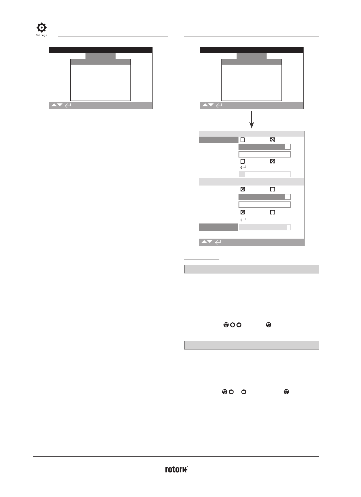
Checkboxes
Checkboxes are indicated by or .
Close Limit
Close Settings
Action Limit Pressure
Pressure Limit
Pressure Mid
Semi Auto Setup
Set Limit
Sensor Position
On Off
Open Settings
1/12
An example for the limit setting checkbox is shown.
Waiting For Status
Close settings
Action Limit Pressure
Pressure Limit
Pressure Mid
Semi Auto Setup
Set Limit
Sensor Position
Open Settings
On Off
1/12
When selected (password entered if applicable, refer to 1.3), the
current mode will be highlighted.
Use either the or to toggle between modes.
Once the required mode is checked, press to select. The
selected mode will be saved and shown as checked on the page.
To exit the checkbox without saving a new setting, press
to return to the page.
90%
0%
15%
95%
0%
0%
Slider controls
Slider controls graphically indicate the set value followed by the
exact numerical value, for example:
To Position
80%
The range covered by the slider is fixed and is determined by
its function.
Waiting For Status
Function Pos % Open
Contact N/O N/C
Pressure Limit
Function Open Limit
Contact N/O N/C
Position
S1
S2
10%
50%
10/40
An example of the S1 indication position value is shown above.
The S1 contact function of Pos.% Open indication will show the
valve position at which the contact will change state.
Press (enter password if applicable). Use or to decrease
or increase the value.
Slider controls wrap round so a key press on a minimum value
will wrap round and indicate the maximum value. The value step
changes increase as either of the keys is held down.
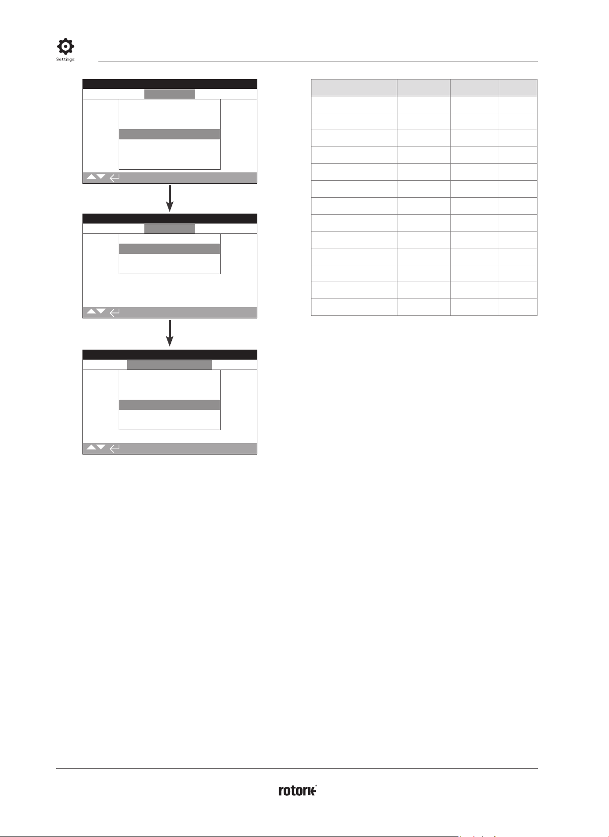
Numerical values
Numerical values relate to fields such as time or address - shown
in the example.
Waiting For Status
Close Settings
Action Limit Pressure
Pressure Limit
Pressure Mid
Semi Auto Setup
Set Limit
Sensor Position
On Off
Open Settings
2/12
Press (enter the password if applicable). Use or to
decrease / increase the numerical value. Press to select when
the correct value is attained.
To exit the numerical value control without saving a new
value, press to return to the previous page.
95%
0%
0%
SI Full Config uration Manu al – Secti on: Introduc tion 5
Page 6

ACTUATOR
SETTING TOOL
1.1 Using the Rotork Setting Tool continued 1.2 Connecting to the Actuator
The Rotork Bluetooth® Setting Tool Pro incorporating Bluetooth
wireless technology is shown below. It is identified by the key
symbols and a clear band between the top and bottom casings
being transparent.
The Rotork Infrared Setting Tool Pro is identified by solid yellow
keys and a yellow band between casings:
Yellow: Rotork Infrared Setting Tool Pro
Clear: Rotork Bluetoot h® Setting Tool Pro
Connecting to the actuator using Bluetooth
The actuator must be powered up to connect using Bluetooth. The
default security set in the actuator for Bluetooth connection is by
initiation using an Infrared command. This means that the user must
be in close proximity and in direct line of sight of the actuator.
Point the setting tool at the Infrared sensor located at the lower
right of actuator display window within a range of 0.25 m (10")
and press key until the key flashes blue.
The screen will change to the Main Menu screen.
Close Limit
Settings
Data Log
The setting tool will automatically connect using
Bluetooth which takes up to 5 seconds.
Connection is indicated by a blue light on the tool and in the
actuator display window. Once connected, the tool can be used
without pointing it at the display window.
Bluetooth connection will be maintained while setting tool key
commands are made. After a period of 5 minutes with no key
commands, Bluetooth connection will be turned off and the
setting tool and display blue lights will go out. To manually
disconnect Bluetooth at any time, press and keys together.
Status
Assets
Connecting to the actuator using Infrared
Infrared communication is used when:
1. Bluetooth communication has been disabled.
2. Legacy Infrared tool is used (yellow banded).
Communication is by direct line of site, within 0.25 m (10"). Keys
have the same function as previously shown.
6 SI Full Conf iguration M anual – Sec tion: Intro duction
Page 7

1.3 Password Security
ACTUATOR
SETTING TOOL
Menus, pages and settings may be viewed when the actuator is
set to Remote, Stop or Local. To change a setting, the actuator
must be selected to Local or Stop using the red selector and the
correct password must be entered.
The password will be requested the first time a function
is selected. Once correctly entered, other changes can be
made without re-entering the password for the duration
of the setting tool session with the actuator.
If the actuator is selected to Remote and a setting is selected, the
following will be displayed:
Open Limit
Press the key to return to the previous page. Set the red
selector to Local or Stop to proceed with the setting change.
With the actuator correctly selected and when any setting
function is selected, the password screen will be displayed.
If the user has set their own password the following screen will
be displayed:
Waiting For Status
ROTACT
Enter user selected Password:
Use key to highlight new password entry box
and press key.
Use keys to scroll through alphanumeric values to display
required character.
Use key to move to the next character.
Use key to delete the highlighted character.
Use key when selected password is complete.
Navigate to the OK button using the
accept the password.
Password levels
Viewer − ROTORK
Modify − R OTACT
keys then press to
The factory set default password ROTORK is displayed and the
OK button is highlighted.
Press key. The setting page from which the function
was selected will be displayed with the function
highlighted.
SI Full Config uration Manu al – Secti on: Introduc tion 7
Page 8
2. Settings 2.1 Settings − Limits
Close Limit
Settings
Limits
Stroke Tests
Indication
Control
Security
Defaults
Service
2. Settings Menu Page
2.1 Limits 8
2.2 Stroke Tests 11
2.3 Indication 13
2.3.1 Contacts 13
2.3.2 Local Display 15
2.3.3 Analogue 16
2.4 Control 16
2.4.1 Local Control 17
2.4.2 Remote Control 18
2.4.3 ESD 33
2.4.4 Stepping Control 34
2.5 Security 35
2.6 Defaults 37
Close Limit
Settings
Limits
Stroke Tests
Indication
Control
Security
Defaults
Service
Close Settings
Action Limit Pressure
Pressure Limit
Pressure Mid
Semi Auto Setup On Off
Set Limit
Sensor Position
Action Limit Pressure
Pressure Limit
Pressure Mid
Semi Auto Setup On Off
Set Limit
Sensor Position
Open Settings
12/12
90%
0%
15%
90%
0%
93%
Close Settings
1/12 Action
The actuator can be configured to Close on pressure or to Close
on limit.
Pressure (default) − The actuator will move the valve to the set
Closed limit and then travel to the mechanical stop.
Limit − The actuator will move the valve to the set Closed limit
position and stop.
To change, press
will indicate the set closing direction.
2/12 Pressure Limit
This setting allows the maximum cut-off pressure while travelling
from the Closed electrical limit to the mechanical end stop to be
set. The value is a % of the maximum available pressure, which is
limited by the pressure relief valve.
Default = 90%
To change press or arrow key then again. The
slider will indicate the set closing pressure %. (Factory
default is 90% of working pressure).
keys then
again. The checkbox
8 SI Full Conf iguration M anual – Sec tion: Set tings
Page 9

2.1 Settings - Limits continued
3/12 Close Pressure Mid
This settings allows the maximum / minimum cut-off pressure
whilst travelling from the Open electrical limit to the Closed
electrical limit. If the value is set for 0, on the slider this then
defaults to the setting previously set for the pressure limit.
Default = 0%
To change press or arrow key then again. The
slider will indicate the set mid travel closing pressure %.
(Factory default is 00).
4/12 Semi Auto Set-up
With the setting switch On the actuator Closed limit is initially
set at the mechanical stop of the valve / actuator with the
software then scaling back this setting by approximately 2% of
travel, to move the electrical limit away from the mechanical
stop. This prevents any issues with failure to reach the electrical
limit when the actuator is in service. Switching Off allows the
actuator to travel further.
Default = ON
To change press
checkbox will indicate the set action. (Factory default is
or arrow key then again. The
Semi Auto set up On).
5/12 Set Closed Limit
A Closed limit position cannot be set if the actuator is at the
Open limit.
If the actuator has been delivered complete with the valve, the
valve maker should have already set the Closed and Open limit
positions, refer to testing below.
The Closed limit is set by ensuring the actuator is at the
mechanical Closed limit position and then pressing key
asbelow.
Close Limit
Close Settings
Action Limit Pressure
Pressure Limit
Pressure Mid
Semi Auto Setup On Off
Set Limit
Sensor Position
Open Settings
95%
0%
15%
The actuator will then display the following instruction.
Move to closed limit
Move the actuator and valve to the Closed position and press
key to select OK. This will set the Closed limit at the current
valve / actuator position and if not previously illuminated,
the Closed limit indication LED (factory default green) will
beilluminated.
Testing: The limit position can be confirmed by opening the
actuator until the indication LED changes colour and then
moving closed until the Closed limit position is displayed and the
LED is turned on at the set Closed position.
6/12 Sensor Position
Sensor Position
15%
This slider shows the current position of the position sensor and
cannot be adjusted, this setting for the Closed limit position
needs to read above 5% to prevent a fault condition occurring.
Open settings
7/12 Open Action
The actuator can be configured to Open on pressure or to Open
on limit.
Pressure − The actuator will move the valve to the set Open
limit and then travel through to the mechanical stop.
Limit (default) − The actuator will move the valve to the set
Open limit position and stop.
To change press
checkbox will indicate the set closing action.
or arrow key then again. The
6/12
Continued over page
SI Full Config uration Manu al – Secti on: Settin gs 9
Page 10

2.1 Settings − Limits continued
8/12 Pressure limit
This setting allows the maximum cut-off pressure while travelling
from the Open electrical limit to the mechanical end stop limit to
be set. The value set is a % of the maximum available pressure,
which is limited by the pressure relief valve. Default = 90%.
To change press
slider will indicate the set closing pressure %.
or arrow key then again. The
9/12 Open Pressure Mid
This setting allows the maximum/minimum cut-off pressure
whilst travelling from the Closed electrical limit to the Open
electrical limit to be set. If the value is set to 0, on the slider, this
then defaults to the setting previously set for the pressure limit.
To change press key then either or arrow
key then again. The slider will indicate the set
closingpressure%.
Default = 0%
10/12 Semi Auto Set-up
With the setting switch On the actuator Closed limit is initially set
at the mechanical stop of the valve / actuator with the software
then scaling back this setting by approximately 2% of travel, to
move the electrical limit away from the mechanical stop. This
prevents any issues with failure to reach the electrical limit when
the actuator is in service. Switching Off allows the actuator to
travel further.
Default = ON
To change press
checkbox will indicate the set action.
or arrow key then again. The
11/12 Set Limit
An Open limit position cannot be set if the actuator is at the
Closed limit.
If the actuator has been delivered complete with the valve, the
valve maker should have already set the Closed and Open limit
positions, refer to testing below.
The Open limit is set by ensuring the actuator is at the
mechanical Open limit position and then pressing key
asfollows.
Open Settings
Action Limit Pressure
Pressure Limit
Pressure Mid
Semi Auto Setup On Off
Set Limit
Sensor Position
12/12
95%
0%
0%
The actuator will then display the following instruction.
Move to open limit
Move the actuator and valve to the Open position and press
key to select OK. This will set the Open limit at the current
valve / actuator position and if not previously illuminated, the
Open limit indication LED (factory default red) will beilluminated.
Testing: The limit position can be confirmed by closing the
actuator until the indication LED changes colour and then
moving Open until the Open limit position is displayed and the
Open LED is turned on at the set Open position.
10 SI Full Conf iguratio n Manual – Sec tion: Set tings
12/12 Sensor Position
This slider shows the current position of the position sensor and
cannot be adjusted. This setting for the Open limit position needs
to be reading below 95% to prevent a fault condition occurring.
Sensor Position
0%
Page 11

2.2 Settings − Stroke Tests
Full Stroke Tests
By utilising this procedure during the initial commissioning of the
actuator assembly, the electronics will give a command to the
actuator to perform a full stroke test from either the Closed or
Open limit, recording the position and pressure against a time
reference.
Before starting this process the actuator requires the
Closed and Open limits to be set.
Close Limit
Full Stroke Tests
Partial Stroke Tests
1/13 Setup
Prior to starting the test place the remote selector switch into the
local position.
Once at the Setup option, press the key to initiate the full
stroke set up, once entered the actuator will run from either the
Closed or Open limit to the opposite position, returning back for
two to three complete cycles. During this process the electronics
will store both the Opening, Closing and ESD times. These times
will be used as a reference for all subsequent full stroke tests and
for setting up the partial stroke reference.
2/13 Setup
To operate the full stroke test, use the Bluetooth setting tool and
press the key. Once this has been done the screen will give a
warning that the full stroke test is about to proceed. Press the
key again to OK this. The full stroke test runs the actuator from
either the Open or Closed limit. If the actuator is at the Open
limit and the full stroke test is selected the actuator will run from
the Open limit to the Closed limit then back to the Open limit.
This will be done two to three times with the times for each
Open and Closed movement are stored in a table found below
this menu selection.
Setup
Test
Result (Last test)
Open (Setup) 8.33
Open (Min) 6.65
Open (Max)
Control
Close Limit
Full Stroke
Full Stroke Times (Secs)
9.98
3/13 Result (Last Test)
The results from the full stroke test are found below this menu.
All timings including the opening time, closing time and ESD
time. Also tolerances will be shown along with the most recent
full stroke test times to compare. If any timing is close to, or is
over the time tolerance a warning will be shown on the screen.
4/13 Open (Setup)
This will show the timing of the actuator's opening speed when
the first full stroke set up was complete.
5/13 Open (Min)
This shows the minimum opening time allowed including the
fixed 10% tolerance.
6/13 Open (Max)
This shows the maximum opening time allowed including the
fixed 10% tolerance.
7/13 Open (Last Test)
The times shown in this menu section is the opening time that
was stored from the actuator on the last test performed.
8/13 ESD (Setup)
This will show the ESD time from when the actuator was first set
up and a test was run.
9/13 ESD (Min)
This shows the minimum time allowed for the actuator to
perform an ESD including the 10% fixed tolerance.
10/13 ESD (Max)
This shows the maximum time allowed for the ESD including the
fixed 10% tolerance.
11/13 ESD (Last Test)
This section shows the time recorded on the last full stroke ESD
test performed.
12/13 Close (Setup)
This section shows the closing time of the actuator when the first
full stroke set up was performed.
13/13 Close (Last Test)
This shows the closing time of the actuator on the most re-cent
full stroke test operation.
1/13
Continued over page
SI Full Config uration Manu al – Secti on: Settin gs 11
Page 12

2.2 Settings − Stroke Tests continued
Partial stroke setup must be done after the full stroke set
up and test have being complete.
By utilising this procedure during the initial commissioning of the
actuator assembly, the electronics will command the actuator to
perform a partial stroke from either the closed or open limit. This
procedure will Open or Close the actuator to a certain position
selected by the operator with the use of a slide bar.
E.g. If the actuator is at the Open limit and a partial stroke is
selected, the actuator will Close to the position setting selected
then Open to 100%.
Before starting this process the actuator requires the
Closed and Open limits to be set.
1/8 To Position
A slider bar is available on this selection to choose what position
the partial stroke operates to. If 80% is selected, from the Open
limit when the actuator is partial stroked it will Close to 80%
then re-open.
Close Limit
Full Stroke
To Position
Partial Stroke Setup
Partial Stroke Test
Result (Last test) Under time to target
ESD (Setup) 1628
ESD (Last test) 461
Normally Closed Settings (ms)
3/8
80%
3/8 Test
When selected the actuator will need to be in the relevant
position. The actuator will perform a partial stroke test moving
from the Open limit to the percentage selected using the use of
the slider bar. The times will be recorded and compared to the
initial partial stroke setup times. If solenoid redundancy is turned
on this test will be performed 2-3 times. Also a partial ESD test
will be performed and the time recorded.
4/8 Results (Last Test)
The results from the partial stroke test are found in this menu. All
operating times including the opening time, closing time and ESD
time are also available. Also tolerances will be shown along with
the most recent full stroke test times. If any times are close to, or
is over the time tolerance a warning will be shown on the screen.
5/8 Open (Set Up)
This shows the time that the actuator opened in when the partial
stroke was first set up.
6/8 Open (Last Test)
This shows the time the actuator opened in on the most recent
partial stroke test.
7/8 ESD (Setup)
This shows the actuator's ESD time when the first partial stroke
was setup.
2/8 Setup
To operate the partial stroke set up with the use of the Bluetooth
setting tool scroll to the ‘Partial Stroke Setup’ and press the the
key. You will then be asked to confirm this, press the key
again and the setup will start.
When this is selected the actuator will Close to the specified
position with the use of the slider bar allocated next to the ‘To
Position’ section on the screen. The setup will partially Close
then Open the actuator recording the times to compare with any
partial stroke tests that are done after the initial partial stroke
setup. If the actuator’s solenoid redundancy is turned on, each
individual solenoid will partial stroke, meaning the actuator will
perform this test 2-3 times automatically. It will also perform a
partial ESD stroke set up and record the time of this operation.
Set partial stroke test
will be run.
Ok to proceed.
8/8 ESD (Last Test)
This shows the actuator's ESD time on the most recent partial
stroke test.
12 SI Full Configurati on Manual – Se ction: Set tings
Page 13

2.3 Settings − Indication 2.3.1 Indication − Contacts continued
Close Limit
Limits
Stroke Tests
Indication
Control
Security
Defaults
Service
Settings
Instruction is provided on:
2.3.1 Contacts
2.3.2 Local Display
2.3.3 Analogue
2.3.1 Indication – Contacts
Close Limit
Indication
Contacts
Local Display
Analogue
Close Limit
Monitor Relay
Mode Available
Temperature Trip
Temp. High oC 60
Temp. Low oC -30
S1
Function Closed Limit
Contact N/O N/C
1/39
Refer to actuator's specific wiring diagram for available contact
relays options.
1/4 Monitor Relay—Mode
The monitor relay provides remote indication of actuator status.
It provides a volt free change over contact, refer to actuator
circuit diagram. There are 2 modes that can be set:
Available (default) – Actuator available for remote control.
Monitors power supplies, motor thermostat, detected internal
fault and remote control selected. A loss in one or more will
cause the monitor relay to de-energise indicating “not available”
for remote control.
Fault – Actuator fault. Monitors power supplies, motor
thermostat and detected internal fault. A loss in one or
more will cause the monitor relay to de-energise indicating
“actuatorfault”.
To change the mode press the enter button on the
Bluetooth setting tool. The actuator will then ask you to
enter the password. Once done use the and arrow
keys then select the setting you require by pressing the
keyagain.
S contact function, contact type and position
Each relay contact can be set to one of the functions shown
in the table below and its contact type can be set as Normally
Open (NO) or Normally Closed (NC). If Pos % Open function is
selected, the position at which the relay operates can be set. For
all other functions the position control slider will be greyed out.
Standard contacts S1-S4, option S5-S8 and S9-S12
contacts when fitted
The method for setting all S contacts is the same. S1 to S4 are
fitted as standard. A further 8 extra contacts are available as
options grouped: S5 to S8 and S9 to S12, refer to actuator wiring
diagram. If extra contacts are fitted their configuration screens
are accessed by scrolling down. If not fitted their configuration
settings will be greyed out.
2/4 Contact Function
The available contact functions included in the drop down list for
each available relay function are shown in the table below.
To change the contact function using the Bluetooth setting
tool select function the relay you are wanting to change
using the enter button, a drop down box will then appear,
use the and arrow keys along with the key when
the desired function is highlighted.
Function Indication:
Function Indication
Disabled Contact relay disabled
Closed limit Closed limit position (exact)
Open limit Open limit position (exact)
Temperature trip Tripped at high or low temperature
Pos % Open Set position mid-travel – Opening and Closing
Stop selected Red selector set to Stop
Local selected Red selector set to Local
Remote selected Red selector set to Remote
P-stroke active Partial stroke underway
P-stroke pass Partial stroke complete
P-stroke fail Partial stroke not complete
Continued over page
SI Full Config uration Manu al – Secti on: Settin gs 13
Page 14

2.3.1 Indication - Contacts continued
Function Indication:
F-Stroke active Full stroke underway
F-Stroke pass Full stroke complete
F-Stroke fail Full stroke not complete
Opening Actuator moving in the Open direction
Closing Actuator moving in the Close direction
Moving Actuator moving in any direction
Motor running The motor is running
General alarm A general alarm is present
Process alarm A process alarm is present
Over press (MID) Actuator over pressured mid travel
Over press (Limit) Actuator over pressured at limit
Over press (ANY) Actuator over pressured
Stall (MID) Actuator stalled mid travel
Stall (LIMIT) Actuator stalled at limit
Stall (ANY) Actuator stalled
Motor thermostat Motor thermostat trip
Control alarm Control alarm present
Lost phase Phase loss (3 phase only)
ESD active Actuators ESD signal active
Manual reset Manual reset is required
Manual operation Manual operation is selected
Actuator alarm Actuator alarm is present
Loss of HMI HMI loss (digital display)
Bluetooth Bluetooth coms
Customer supply Customer supply lost
3/4 Contact Function
Each contact relay can be configured to be normally Open (make
on conduction) or normally Closed (break on conduction).
Normally Open − The contact will complete the circuit when
the set function is present, normally Open.
Normally Closed − The contact will complete the circuit when
the set function is present, normally Closed.
4/4 Position
If the relay function relates to an actuator’s position, for example
Pos % Open, this setting will become available to edit with a
slider bar. A range of 0-100% will be available. To adjust use
the Bluetooth setting tool, enter button along with the left and
rightarrows.
Close Limit
Settings
Limits
Stroke Tests
Indication
Control
Security
Defaults
Service
Close Limit
Indication
Contacts
Local Display
Analogue
Close Limit
LCD
Home Screen Position
Power Save Off
Contrast 52%
LED
Choose LED Green Red
Mid Travel LED On
Alarm LED Disabled
1/3
LCD
The display home screen language can be selected and the
power save mode can be activated within this section.
14 SI Full Co nfigurati on Manual – Se ction: Set tings
Page 15

2.3.2 Indication - Local Display
1/8 Home Screen
Refer to publication − PUB021-057-00.
Available home screens included in the drop down box list are
shown on the next page.
Position − Display indicates the current valve position to
one decimal place. Icons are used for Closed and Open limit
positions.
Pressure (A)+Pos − Display indicates current valve position to
one decimal place as Position (above) plus analogue pressure
indication scaled 0% to 100% of pressure, shown at the top of
the display.
Pressure (D)+Pos − Display indicates current valve position
to one decimal place as Position (above) plus digital pressure
indication scaled 0% to 100% of pressure.
Positioner − Used only with analogue or network position
control. Display indicates current valve position to one decimal
place plus the position equating to the applied demand signal.
In addition, an analogue indication of demand and position is
provided scaled 0% to 100% of valve position.
To set the home screen using the Bluetooth setting tool
use the enter button along with the up and down arrows
to select the desired home screen.
2/8 Power Save
The LCD has a white backlight to maximise contrast of the
segment display and matrix characters. It may be switched off
when not required or if a bright display is disruptive within its
environment.
Off (default) − The display backlight is permanently illuminated
when the actuator is powered up.
On − The display backlight automatically switches off when the
actuator is not operating. The segments / matrix remain on. The
display backlight will switch on when the local control selectors
are moved, electrical or a manual operation takes place or
when the setting tool is communicating with the actuator. The
backlight will switch off again approximately 30 seconds after
the above events have taken place.
To change the power screen using the Bluetooth setting
tool, use the enter button along with the left and right
arrows. The checkbox will indicate the selected mode.
3/8 Contrast
Contrast is the brightness of the screen. This can be adjusted
with the use of a slider bar with values set in %.
To change this use the Bluetooth setting tool’s enter
button along with the left or right arrows.
5/8 Mid Travel LED
On (default) − The yellow lights will illuminate when the
actuator is in mid travel.
Off − The yellow light are off when in mid travel.
Blinker − The yellow light will flash at approximately 0.5 seconds
intervals when in mid travel (electrical or manual operation).
When stationary the lights will remain on.
On / Alarm − The yellow lights are on when in mid travel. If an
alarm is active the yellow lights flash alternately at approximately
0.5 second intervals. Refer to 6/8 Alarm LED.
Off / Alarm − The yellow light are off in mid travel. If an alarm
is active the yellow light flash alternately at approximately 0.5
second intervals. Refer to 6/8 Alarm LED.
Information regarding the nature of the alarms will be shown at
the top of the display.
6/8 Alarm LED
Alarm LED function will be greyed out unless 5/8 mid travel LED
is set to On / Alarm or Off / Alarm.
Disabled (default) – The yellow lights do not indicate an
activealarm.
Alarms – The yellow lights indicate active alarms.
Service – The yellow lights indicate active service alarms only.
A service alarm indicates the actuator requires service.
Information regarding the nature of the alarm(s) will be shown at
the top of the display.
7/8 Alarm LED
The LCD / LED test function operates a test procedure to check all
of the local display functions. It will cycle periodically between
screen and LED functions to provide visual indication that the
display is in fully working order.
Press the enter button on the Bluetooth setting tool to begin
thetest.
8/8 Language
The language used on the display can be selected.
English (default) as standard. Other available languages
may be downloaded from the Rotork website, loaded into the
setting tool using Insight2 and uploaded into the actuator. Visit
www.rotork.com
4/8 Close Colour
Green (default) − The green lights illuminate at the Closed limit
position and red lights illuminate at the Open position.
Red − The red lights illuminate at the Closed position and the
green lights illuminate at the Open position.
This can be changed using the Bluetooth setting tools
enter button along with the left and right arrows to select
the checkbox.
SI Full Config uration Manu al – Secti on: Settin gs 15
Page 16

2.3.3 Indication − Analogue 2.4 Settings − Control
Close Limit
Limits
Stroke Tests
Indication
Control
Security
Defaults
Service
Contacts
Local Display
Analogue
Invert On Off
Set CPT Low
Set CPT High
1/3
Settings
Close Limit
Indication
Close Limit
Analogue
Analogue position indication screen is shown above with
the default setting.
Analogue position indication (4-20 mA) is an optional extra, refer
to circuit diagram for inclusion. If the option is not fitted the
analogue menu item will not be present in the indication menu.
The analogue output signal auto ranges to the set limits and
cannotw be calibrated.
Close Limit
Settings
Limits
Stroke Tests
Indication
Control
Security
Defaults
Service
Instruction is provided on:
2.4.1 Local control
Settings for vandal resistant build, setting tool control,
maintained local control, delay control and action on
loss of actuator user interface.
2.4.2 Remote Control
Settings for control source, hardwired, networks,
analogue and partial stroke setup.
2.4.3 ESD
Refer to actuator wiring diagram.
Control under an ESD control signal has higher priority
than local or remote Open / Closed signals. For ESD,
the control signal must be maintained for the duration
of the ESD action required.
2.4.4 Stepping Control
This is used to control closing and / or opening times
under both local and remote control however, it can
only be used on the hydraulic stroke.
Stepping control is used when the operator is
required to achieve a certain time in the hydraulic
strokedirection.
1/1 Invert
Off (default) − 4 mA output at the Closed limit position and
20mA output at the Open limit position.
On − 4 mA output at Open limit position and 20 mA output at
the Closed limit position.
To change this with the use of the Bluetooth setting tool,
use the enter button along with the left and right
arrows to check the checkbox of the required mode.
16 SI Full Co nfiguratio n Manual – Section: Set tings
Page 17

2.4.1 Control − Local Control
Close Limit
Local
Remote
Temporary Loss
Stepping control
Vandal Disabled
Setting Tool On Off
Maintained On Off
Delay Control On Off
Dead Man Local On Off
Loss of HMI Stayput Remote
Enabled On Off
1/7
Control
Open Limit
Local
Remote Hand Station
The local control configuration page is shown with the
defaultsettings.
1/7 Vandal
Actuator’s built as vandal resistant type 1 do not have the black
and red control selectors fitted. Selection of local control (using
the setting tool Open, Close and Stop keys) and remote control is
made using the vandal setting:
Disabled (default) – Actuator is not vandal resistant build and
control selectors are present.
Local – Actuator selected for Local control using the setting tool
(Bluetooth or Infrared), refer to 1.1. Infrared local control has a
range of approximately 0.25 m (10”) and must be in direct line
of site. Bluetooth local control has a range up to approximately
10m (30 ft.) depending on environment.
Remote – Actuator selected for Remote control. Setting tool
control keys are inactive and the actuator responds only to
remote control signals.
2/7 Setting Tool
With control selectors fitted to the actuator, the Bluetooth
setting tool Close, Open and Stop control keys can be used to
operate the actuator:
On (default) – Setting tool control keys active, control is
possible only when the red selector is set to Local, refer to 1.1
– Using the setting tool. Infrared local control has a range of
approximately 0.25 m (10”) and must be in direct line of site.
Bluetooth local control has a range up to approximately 10m
(30ft.) depending on environment. The black Close / Open
selector remains active.
Off – Setting tool Close, Open and Stop control keys are
disabled. Local control is by Close / Open / Stop selectors fitted to
theactuator.
3/7 Maintained
Sets the action as a response to local Open or Close
controlsignals:
On – The actuator will self-maintain as a response to a fleeting
local Open or Close control signal. It will run until it receives
a Stop command, it reaches a travel limit or is reversed –
maintained control.
Off (default) – The actuator will run only while an Open or
Close control signal is applied – push to run local control.
4/7 Delay Control
If there is a risk of a local Close or Open control signal being
applied due to the selector moving inadvertently or by being hit
momentarily, a delay can be set to help prevent an unintended
operation:
On (default) – A local Close or Open signal must be held for
approximately 2 seconds before the actuator responds.
Off – The actuator responds immediately to a local Close or
Open control signal.
5/7 Dead Man Local
Sets the action as a response to local Open or Close
controlsignals:
On – Local control signal must be maintained, when the local
controls return neutral (either Open or Close) the actuator will
return to the failsafe position.
Off (default) – Actuator will respond normally to local
controlcommands.
6/7 Loss of Human Machine Interface (HMI)
The H
MI consists of the actuat
selectors. If f
of the actuat
or any reas
or ca
n be set.
Stay put – The actuat
relay. It will not res
R
emote (default) – The actuat
pond to remote cont
relay. It will continue to res
or display a
nd red and blac
on the HMI stops responding, the res
or will stay put a
nd alarm using the monitor
rol signals.
or will alarm using the monitor
pond to remote cont
rol signals.
k
ponse
To change this setting with use of the Bluetooth setting
tool use the enter button along with the left and right
buttons . The checkbox will indicate the selected HMI
failure response.
7/7 Remote Hand Station
When fitted, the Remote Hand Station (RHS) can be enabled by
this setting.
Enabled – No (default) – RHS not activated and the sub-menus
will be hidden.
Enabled – Yes – RHS enabled and the sub-menus will appear in
the main Control menu. Refer to PUB002-059 for full setup.
SI Full Config uration Manu al – Secti on: Settin gs 17
Page 18
2.4.2 Control − Remote Control
Close Limit
Limits
Stroke Tests
Indication
Control
Security
Defaults
Service
Local
Remote
ESD
Stepping Control
Hardwired
Control Source
Positioning
Pressure Control
Auxiliary Mask
Analague
Settings
Close Limit
Control
Close Limit
Remote Control
Throughout this section instruction is provided on the set
up of standard, hard wired and remote control options.
The remote control menu is shown above listing all possible
entries. Some menu items shown are optional remote control
forms requiring additional hardware to be fitted within the
actuator. The menu displayed on the actuator will show only the
options fitted.
Options not fitted will not be shown or included in the menu list.
Check the actuator's specific wiring diagram for option inclusion.
The table on the right lists all available standard and option
remote control forms. Their type and the section of this manual
where instruction is provided.
Remote Control Form Included as: Type Section
Hardwired Standard Hardwired 2.4.2-1
Control source Standard Software 2.4.2-2
Positioning Option See note 2.4.2-3
Pressure control 2.4.2-4
Auxiliary mask Option See note 2.4.2-5
Analogue Option Analogue 2.4.2-6
Pakscan Option Network 2.4.2-7
Profibus Option Network 2.4.2-8
HART Option Analogue 2.4.2-9
Modbus Option Network 2.4.2-10
Extra I/O* Option Hardwired 2.4.2-11
Foundation Fieldbus* Option Network N/A
Device Net Option Network N/A
* When Foundation Fieldbus is fitted it will be included in the
remote control menu for information only. The Foundation
Fieldbus option is configured remotely over the Fieldbus network
and therefore does not have a setup page. Control source,
positioning and auxiliary mask pages will be included to allow
associated setting to be made when Foundation Fieldbus
isfitted.
* Extra I/O is an option card providing additional digital inputs
to the standard build. Inputs may be control or indication
(configurable).
Note: When any of the analogue or network remote control
options are fitted, auxiliary mask and positioning are
automatically included in the remote control menu. These items
allow access to settings that are common to all fitted options.
18 SI Full Conf iguratio n Manual – Sec tion: Set tings
Page 19

2.4.2-1 Remote Control − Hardwired
Close Limit
Remote Control
Hardwired
Control Source
Positioning
Pressure Control
Auxiliary Mask
Analogue
Reset on Power
Hardwired
2-Wire Priority Stayput
Fast Remote On Off
1/2
1/2 2-Wire Priority
This sets the action that the actuator will perform when a Closed
and Open signal are both applied simultaneously. Hardwired
remote control form C uses the priority action (Open or Closed)
to set the actuator’s response when two signals are applied.
Refer to the actuator’s wiring diagram and its referenced RWS
controldiagram.
On applying hardwired Close and Open signals together the
actuator will:
Open − The actuator will move Open.
Stay put (default) − The actuator will not move, or will stop if
the actuator is currently running.
Close − The actuator will move Closed.
To change this setting, with the Bluetooth setting tool
use the enter button along with the up and down arrows
toselect.
2/2 Fast Remotes
This is only available on a 24 VDC signal NOT on AC inputs.
The setting will determine how long a signal needs to be present
for it to carry out the specific command.
On − When a remote signal is given, the actuator will wait
100ms before moving.
Off − When a remote signal is given, the actuator will wait
200ms before moving.
SI Full Config uration Manu al – Secti on: Settin gs 19
Page 20

2.4.2-2 Remote Control − Control Source
Close Limit
Limits
Stroke Tests
Indication
Control
Security
Defaults
Service
Hardwired
Control Source
Positioning
Pressure Control
Auxiliary Mask
Analogue
Ctrl Source 1 Disabled
Ctrl Source 2 Disabled
Ctrl Selection Hardwired
Analogue
Disabled
Disabled
1/15
Settings
Close Limit
Remote Control
Close Limit
Option Control
Option Control
Introduction
In addition to standard hardwired control, the actuator can have
up to two remote control options fitted. For most remote control
systems employed by end-users, only one control option is used.
For control systems using analogue control only or where
analogue and network (such as Modbus) control is used. Control
(hardwired / analogue or analogue / network) can be switched
by the user using the manual / auto input available with the
analogue option and the settings made in control source.
When analogue and network options are fitted and analogue
is switched to control, the network option cannot control the
actuator but will continue to report actuator status.
The control source will be set by Rotork to the defaults
required for the option(s) fitted. Refer to table: Control
Source Settings.
For analogue control, if both manual (hardwired control
inputs) and auto (analogue control) is to be used, the
control selection will require re-setting. If only analogue
control is required, the default settings for control source
will be correct. Refer also to 2.3.2-6.
The control source is used to:
• Control source 1 / source 2 - Associate fitted control option(s)
to a source of control (source 1 or source 2).
• Control selection - Set which control source (1 or 2) has
priority when manual / auto input is used to switch between
analogue and network option source.
• Lost signal - Determines the actuator response to a lost
analogue signal or network communication.
The control source settings page shown above is an
example of an actuator with the analogue remote control
option. The actuator display will indicate fitted options.
- Refer to wiring diagram for options fitted.
Table: Control Source Settings
Control Source Settings
Option Control
Settings
Hard wired
(No Options)
Analogue only
Analogue and
Hardwired
Network Only
Analogue and
Ctrl Source 1 Disabled Analogue Analogue Network Analogue
Ctrl Source 2 Disabled Disabled Disabled Disabled Network
Ctrl Selection Hardwired Source 1
Hardwired /
Source 1
Source 1
Options Fitted
Disabled Analogue Analogue Network Network
Disabled Disabled Disabled Disabled Analogue
Disabled Disabled Disabled Disabled Disabled
Disabled Disabled Disabled Disabled Disabled
Network
Source 1 /
Source 2
20 SI Full Confi guration Ma nual – Sect ion: Setti ngs
Page 21

2.4.2-2 Remote Control − Control Source continued
1/15 Control Source 1
Control source 1 will be set by Rotork for the fitted remote,
Analogue or Network control option(s). Refer to table: Control
Source Settings.
2/15 Control Source 2
Control source 2 will be set by Rotork for the fitted remote,
analogue or network control option(s). Refer to table: Control
Source Settings.
3/15 Ctrl Selection
Control selection is used to select the control source. Also if
required, for analogue with network options, allowing hardwired
switching between sources using the manual / autoinput.
Disabled − All remote control disabled. The actuator can only be
operated using the local controls.
Hardwired − Remote control by hardwired inputs only. This
setting is the default for actuator’s with no option cards fitted.
If a network option is fitted but is only required for
monitoring, hardwired must be selected.
Source 1 − Control by the option listed for control source 1.
If control source 1 is a network option, control will be via its
auxiliary mask inputs. Refer to 2.3-2.5.
Hardwired / Source 2 − Control availability only when analogue
option is fitted. This mode enables users to select between
control by hardwired inputs or source 1 (analogue) control by
applying or removing a signal to the manual / auto input (refer to
wiring diagram). Manual will enable hardwired control and auto
will enable source 1 control.
If an analogue option is fitted and manual / auto switching
is required, hardwired / source 1 will be required to be
selected.
Source 1 / source 2 − For future use with two Network
controloptions.
4/15 to 6/15 Options Fitted
Not editable. Factory set for the control options fitted. Up to 3
options can be fitted and will be indicated in the list. Unused
allocations will be set to disabled.
If a control option is fitted after manufacture, the allocation will
be set to the fitted option type by Rotork Service. Where the
user upgrades an actuator to include a new control option using
a kit supplied by Rotork, this must be set before the control
mode settings can be made. Contact Rotork for access.
7/15 to 15/15 Lost Signal
Sets the actuator response for when the analogue signal
or network communications of the control source are lost.
There are three settings for determining the actuator’s response
on loss of signal. These are all common for each type of option
fitted. Each group of three will be headed with the applicable
option type. For actuator’s including one control option, settings
8/19 to 10/19 will be available while settings 11/19 to 19/19
will be greyed out. For two options fitted, 8/19 to 13/19 will be
available and so on until up to four options. This instruction is
therefore common for as many options as are fitted.
7/15 Lost Signal Time
Sets the amount of time in seconds that a signal must be lost
before the lost signal action is performed. Range, 0 to 65
seconds. Default is set as 1 second.
For the analogue option, time must be set to 0 seconds.
To change this using the Bluetooth setting tool use
the enter button along with the left and right
followed by the enter arrow as select. The time set
after which the lost signal action will be implemented
asindicated.
8/15 Lost Signal Action
Sets the action to be performed when the signal is lost.
Off (Default) − the lost signal feature is disabled. An actuator
with analogue control will run to the set low signal position. An
actuator with network control will stay at its current position
when communication / signal is lost.
Stay put − If the actuator is not moving it will stay put. If it is
moving the movement will stop in that position.
De-energise all − All solenoid will de-energise.
Close − The actuator will run to the Closed limit.
Open − The actuator will run to the Open limit.
Position − the actuator will run to the mid travel position set for
signal loss position, refer to 9/15.
To change these settings using the Bluetooth setting tool
press the enter button along with the up and down
arrows
until the required selection on the drop down
box is highlighted. Follow up with the enter button .
The selected action will be indicated.
9/15 to 15/15 Lost Signal
When the lost signal action is set to position the actuator will
run to the mid travel position set. Range is 0% (Closed limit) to
100% (Open limit). This control should be used if a lost signal
position in mid travel is required.
Whenever the actuator is running under positioning mode, the
parameters in the positioning menu will apply. Refer to 2.4.2-3.
SI Full Config uration Manu al – Secti on: Settin gs 21
Page 22

2.4.2-3 Remote − Positioning
Close Limit
Limits
Stroke Tests
Indication
Control
Security
Defaults
Service
Hardwired
Control Source
Positioning
Pressure Control
Auxiliary Mask
Analogue
Deadband Close
Hysteresis Close
Deadband Open
Hysteresis Open
Slow Mode
Current Demand
1/6
Settings
Close Limit
Remote Control
Close Limit
Positioning
0.00
0.8%
0.1%
0.8%
0.1%
5%
The positioning option settings page with its default
settings is shown above.
Applicable for analogue and HART control options and
also for all network control options where positioning
control is required. Settings are used to tune the actuator
positioning response.
• Deadband and hysteresis are combined to set
positioningaccuracy.
• Low / high signal position sets the range of the valve stroke
where positioning is required.
1/6 Deadband Close/Open
Range − 0% to 10% Defaults = 1%.
Affects positioning accuracy as a response to the process control
system desired value (DV) signal position. A smaller deadband
increases accuracy, however the widest deadband should be
set whilst maintaining good control in order to protect the
mechanical valve from excessive wear and / or to keep the
actuator within its electrical rating.
Deadband setting should be combined with 2/5 hysteresis
setting. The actuator will run towards the DV position until the
actual position is within the set deadband minus the hysteresis
setting. This has the effect of the actuator stopping nearer to the
DV position. The actuator will not restart unless it overshoots and
runs outside the deadband or a new command places the new
desired position outside the deadband. Refer to figure 2.4-1.
To change settings using the Bluetooth setting tool use
the enter button along with the left and right arrows
with the use of a slider bar until the desired % is
found. Use the enter button to select.
2/6 Hysteresis Close/Open
Range 0% − 10% Default setting = 0.5%.
Hysteresis affects positioning accuracy as a response to the
process control system desired value (DV) signal position. A larger
hysteresis setting will increase accuracy but the value set must
not be greater than that set for deadband.
Hysteresis setting should be combined with 1/5 deadband
setting. The actuator will run towards the DV position until the
actual position is within the set deadband minus the hysteresis
setting. This has the effect of the actuator stopping nearer to the
DV position. The actuator will not restart unless it overshoots and
runs outside of the deadband or a new command places the new
desired position outside the deadband. Refer to figure 2.4-1.
To change settings using the Bluetooth setting tool use
the enter button along with the left and right arrows
with the use of a slider bar until the desired % is
found. Follow up with enter as the select button.
22 SI Full Confi guration Ma nual – Sect ion: Setti ngs
Page 23

2.4.2-3 Remote − Positioning continued
Slowband (8%) Slowband (8%)
Initial direction of travel
SLOW
SLOW
Actual stopped position
3/6, 4/6, 5/6, 6/6 Deadband, Hysteresis, Slowband &
Selectable slowband, deadband and hysteresis values are used
to determine how closely the actuator position will match the
demand signal. Proper calibration settings provide accurate
positioning, prevent the system from hunting and reduce the
number of pump/motor starts. Some understanding of the
operational design parameters is required to optimally set
deadband ‘DB’, hysteresis ‘HS’ and slowband ‘SL’. The chart
below shows how the slowband, deadband and hysteresis
settings effect control of the actuator.
A slowband of 8%, deadband of 5% and hysteresis of 2% is
shown with a demand position of 50%. If the actuator is started
at 40%, the controller will command it to move in the Open
direction until it reaches 42% (demand-slowband). It will then
move Open at a slower rate until it reaches 47% (deadband-
Current Demand Example
STOP
42%
START
45%
OPENING
47%
DEMAND
POSITION
50%48%
(deadband-hysteresis)). Momentum/solenoid response time
within the system may cause the actuator to continue moving
after the Stop command has been issued as shown by the
‘actual stopped position’ at 48%. Movement is not commanded
again until the measured position falls outside of the deadband
on either side of the deadband position. If the deadband was
smaller, it would be possible for the actual stopped position to
have fallen the other side of the deadband in which case, the
actuator would be commanded to move in the opposite direction
to meet the demand. This would result in hunting as the actuator
oscillated around the demand point. By increasing the deadband
and also increasing the amount of hysteresis, the actual demand
position can be met without hunting occurring. Outside of the
slowband (<42% & >58%) normal fast operation should occur.
To change with the Bluetooth setting tool use the enter
button along with the left and right arrows to
select the desired position on the slider bar.
STOP
CLOSING
53%
START
55%
58%
Hysteresis (2%)
Deadband (5%)
Figure 2.4-1 Example of Positioning Control using Slowband (8%), Deadband (5%) and Hysterisis (2%)
Deadband (5%)
Hysteresis (2%)
SI Full Config uration Manu al – Secti on: Settin gs 23
Page 24

2.4.2-4 Remote Control − Pressure Control
Close Limit
Remote Control
Hardwired
Control Source
Positioning
Pressure Control
Auxiliary Mask
Analogue
Close Limit
Pressure Control
Hold Pressure On Off
Deadband Over
Deadband Under
1/3
5%
5%
1/3 Hold Pressure
This setting allows the user to decide what action the actuator
should take if it drifts from its current position (across the full
actuator stroke), until another command to move is given.
This feature will compensate for any drift that occurs in
either direction by operating either the pump or solenoid to
maintainposition.
2/3 Deadband Over
This feature is used for pressure compensation to vent the
internal hydraulic pressure in the actuator in the event of thermal
expansion due to temperature fluctuations. Factor y default
setting is 10% with it being selectable between 0% - 25%.
3/3 Deadband Under
This feature is used for pressure compensation to increase the
internal hydraulic pressure in the event of the pressure falling
to a set defined value while the actuator is at a position limit.
This type of compensation is to allow for thermal contraction
again due to temperature fluctuations, with the default setting
being5%.
24 SI Full Config uration Manual – Sect ion: Settin gs
Page 25

2.4.2-5 Remote Control − Auxiliary Mask
Close Limit
Remote Control
Hardwired
Control Source
Positioning
Pressure Control
Auxiliary Mask
Analogue
Close Limit
Auxiliary Mask
Auxiliary 1
Contact 1
Auxiliary 2
Contact 2
Auxiliary 3
Contact 3
1/6
Dig in Open
N/O N/C
Dig in Close
N/O N/C
Dig in Maint
N/O N/C
The auxiliary mask setting page is shown above.
Introduction
When a network option is fitted (Pakscan / Profibus / Modbus /
Foundation Fieldbus or HART) a facility to accept three auxiliary
inputs is available. Auxiliary inputs can be set as supplementary
control for the actuator (Open, Close, Stop / maintain) or as
digital indication inputs whose status is reported over the option
network. It is also possible to have a combination of both
supplementary remote control and digital inputs to provide. For
example, Open and Closed control. As well as high and low tank
level alarm indication from external level transducers.
Auxiliary inputs are in addition to the standard control and
feedback features incorporated into a network option. Auxiliary
inputs are connected to the standard Open, Close and Stop /
maintain inputs. Refer to wiring diagram.
Each auxiliary input can be set for the type of contact connected.
Refer to auxiliary input setup.
Auxiliary Input Setup
Input Auxiliary 1 Auxiliary 2 Auxiliary 3
Control Open Closed Stop / maintain
Indication Dig Dig Dig
Contact type Contact 1 Contact 2 Contact 3
Normally Open N/O N/O N/O
Normally Closed N/C N/C N/C
A normally Open contact is considered to be in the active
state when the contact is Closed. A normally Closed contact is
considered to be in the active state when the contact is Open.
(Using auxiliary 1 and contact 1 as an example).
1/6 Auxiliary 1
Refer to auxiliary input setup.
Dig in (default) − Network option will report digital input
status: 1 or 0.
Open − Hardwired Open command signal is required. Use
auxiliary 2 to 4 for Close or Stop / maintain.
To change with the use of the Bluetooth setting tool,
use the enter button along with the left and right
arrows . The checkbox indicates the set auxiliary 1
inputfunction.
2/6 Contact 1
Refer to auxiliary input setup.
N/O (default) − A normally Open contact is used to derive
input.
N/C − A normally Closed contact is used to derive input.
To change with the use of the Bluetooth setting tool,
use the enter button along with the left and right
arrows . The checkbox indicates the set contact 1
input type.
Continued over page
SI Full Config uration Manu al – Secti on: Settin gs 25
Page 26

2.4.2-6 Remote Control − Analogue Option
Close Limit
Remote Control
Hardwired
Control Source
Positioning
Pressure Control
Auxiliary Mask
Analogue
Close Limit
Analogue
Signal Type
Signal Range
Invert
Manual-Auto
Signal To Close
Signal To Open
1/6
mA Volts
20mA
On Off
On Off
The analogue option setting page is shown above.
The analogue menu item and its associated settings page will
only be shown when the analogue option is fitted. Refer to
wiring diagram. The analogue option settings page allows the
option to be set for the applied signal type and range. Signal low
and high values can also be calibrated.
For analogue options; deadband, hysteresis and
positioning settings, refer to 2.3.2-3.
1/6 Signal Type
mA (default) − Set for current (mA) Analogue control signal.
Volts − Set for voltage analogue control signal.
To change using the Bluetooth setting tool press the enter
button along with the left and right arrows
find the desired setting within the checkboxes.
to
2/6 Signal Range
Available ranges: 5 mA, 10 mA or 20 mA (default). 5 V,
10V or 20 V range for voltage control. For analogue signal
using 4 mA to 20 mA range, set 20 mA.
To change using the Bluetooth setting tool use the enter
button along with the up and down arrows
select the desired setting in the drop down box.
to
3/6 Invert
Off (default) − Lowe analogue signal will move the actuator in
the Close direction.
On - High analogue signal will move the actuator in the Close
direction.
To change using the Bluetooth setting tool press the enter button
along with the left and right arrows to find the desired setting
within the checkboxes.
4/6 Manual-Auto
With the analogue control option it is possible to have
manual / auto control by a user supplied remote switch selection.
Analogue Option
Fitted
Manual Hardwired Network
Auto Analogue Analogue
Analogue and
Network Options
fitted
When analogue and network options are fitted and auto is
selected, the network option fitted will continue to report
actuator status.
Hardwired ESD is available in both manual or auto. When
applied, ESD will override all other control signals.
For manual auto control, refer to wiring diagram and
referenced RWS diagram.
Off (default) − Manual / auto control is not used. Actuator will
be controlled by the analogue signal. Where a Network option
is also fitted, the network option will report the actuator’s
statusonly.
On − The actuator can be controlled by hardwired contacts or
the network (as applicable) or by the analogue signal.
To change using the Bluetooth setting tool press the enter
button along with the left and right arrows
find the desired setting within the checkboxes.
to
5/6 Set to Close
The actuator must be calibrated to the Close signal value. By
measuring this signal it will then be able to control the actuator
by moving it to the set to Close signal position, refer to 2.3.2-3
Apply the Close signal and select. The signal will be
measured and set as the Close signal position value.
6/6 Set to Open
The actuator must be calibrated to the Open signal value. By
measuring this signal it will then be able to control the actuator
by moving it to the set to Close signal position, refer to 2.3.2-3
Apply the Open signal and select. The signal will be
measured and set as the Close signal position value.
26 SI Full Confi guration M anual – Sec tion: Setti ngs
Page 27

2.4.2-7 Remote Control − Pakscan
Analogue
Pakscan
Profibus
HART
Modbus
Extra I/O
Remote Control
Pakscan
Address 1
Baud Rate 1200
Position
Update Time (s) Disabled
Deviation Disabled
Torque
Update Time (m) 1
Deviation Disabled
Filter Manual Auto
Valve Travel Time 1000
1/8
The Pakscan control option settings page is shown above
with its default settings. Pakscan is a control option, refer
to wiring diagram.
Depending on the Pakscan control scheme, other related settings
may be required, refer also to:
• 2.3.2-3 Positioning
• 2.3.2-5 Auxiliary Mask
1/8 Address
The Pakscan field control unit option must be allocated a unique
loop node address. Change made to the address will take effect
immediately. The range of address is 1 - 240.
2/8 Baud Rate
The actuator Pakscan Field control unit option must be set to
the loop baud rate. For Pakscan 2-wire control loop the selected
baud rate must be common in the master station and all the
field units included in the loop. Changes made to baud rate will
take immediate effect. The baud rate is selectable using the
drop down list box and the selections are: 110, 300, 600, 1200
and 2400.
3/8 Update Time(s)
Range 0 (disabled ) to 255 seconds.
Set when mid-travel positioning control is required. Update
time in seconds is the set period for updating the master station
with position. Refer to 4/6 deviation. The valve position will be
reported at time intervals equating to the set update time. If the
FCU updates to deviation whilst the valve is moving then the
update time should be set to approximately 10 times the loop
scan time. If the actuator is not used for mid-travel positioning
(i.e. isolating duty) then the update time should be turned off by
setting the time to zero (disabled).
4/8 Devi ati on (%)
Range 0 (disabled ) to 225 seconds.
This is set when mid travel positioning is required. Deviation is
the set amount of change that has to occur before the position
data is reported to the master station. Whilst the valve is in
motion, reports about its position will be made each time
the position changes by more than the deviation setting. The
recommended value is 5% where positioning data is required. If
the actuator is not used for mid-travel positioning (i.e. isolating
duty), then the deviation should be turned off by setting it to
zero (disabled).
Continued over page
SI Full Config uration Manu al – Secti on: Settin gs 27
Page 28

2.4.2-7 Remote Control − Pakscan continued
5/8 Update Time (m)
Range 5 to 255 minutes. Setting below 5 will
indicatedisabled.
Pressure update time (minutes) value is refreshed from a
stationary actuator. If pressure data is not required then its
update time should be disabled.
6/8 Deviation
Range 5% to 99%. Setting below 5% will indicate
disabled.
Set for amount of change in actuator measured pressure that has
to occur before pressure data is reported to the master station.
During valve travel pressure reporting will be made each time
the pressure changes more than the deviation setting. Where
continuous pressure data is required the recommended value is
5%. If pressure data is not being used then the deviation should
be set to disabled.
7/8 Filter
Set to enable or disable auto reporting of the historical
pressurelogs.
Auto − The Pakscan option will automatically report the 6
historical pressure logs for each direction once the actuator has
stopped at limit. The historical log will contain the instantaneous
value of pressure for both Closing and Opening pressure logs.
Manual − The historical pressure logs are not automatically
updated. Historical logs are read on demand using the master
station command. In manual, the historical logs will contain
the averaged (or filtered) pressure logs, i.e. the data from the
actuator’s average pressure logs.
8/8 Valve Travel Time
Range 0 to 18000 seconds.
Valve travel time should be set at a value that is 10% greater
than the actual valve travel stroke time (i.e. Open to Close). If
the valve travel time is exceeded, an alarm will be raised via the
Pakscan network.
28 SI Full Confi guration Ma nual – Sect ion: Setti ngs
Page 29

2.4.2-8 Remote Control − Profibus
Analogue
Pakscan
Profibus
HART
Modbus
Extra I/O
Remote Control
Profibus
Address 126
GSD Param. Yes No
Termination1 On Off
Termination2 On Off
Redundancy Flying System
Extended Diag. Yes No
1/6
The Profibus control option settings page is shown above
with the default settings. Profibus is a control option and
is available in single and dual versions.
Refer to wiring diagram.
Depending on the Profibus control scheme. Other related
settings may be required, refer also to;
• 2.4.2-3 - Positioning
• 2.4.2-5 - Auto Mask
1/6 Address
The actuator Profibus module must be allocated a unique
address in the Profibus system. Changes made to the address will
take effect immediately. The range of address is 1 to 126 (default
126). Refer also to redundancy.
1/6 GSD Parameter
If the user parameterisation date is to be setup using FDT, EDDL
or the actuator’s menu, setting the menu item to No will ensure
that the user parameterisation data sent to the Profibus card
during the parameterisation of the Profibus network with the
GSD file will be ignored. The setting previously made will not be
overwritten. Default this is Yes to ensure that the Profibus card
will be parameterised by the GSD user parameterisation data.
Yes (default) − Parameterisation by GSD file is enabled.
No − Parameterisation by GSD file is disabled.
3/6 to 4/6 Termination 1 − Termination 2
Profibus networks require active termination at each end of the
highway. Profibus option has active termination (2 sets for dual)
built in, which can be switched in or out of the circuit.
Off (default) − termination resistors switched out.
On − termination resistors switched in.
5/6 Redundancy
Used for dual Profibus option (redundant) only. Refer to
wiringdiagram.
System (default) − System redundancy means that there are
two completely separate Profibus highways in the network
system and that each highway is connected to one of the
Profibus channels. In this mode the address of both Profibus
channels are identical.
Flying − Flying redundancy means that there is one highway that
is connected to both channels, in this mode the address of the
channels must be different to avoid both channels responding to
the same message. In flying redundancy channel two address will
be channel one address plus 64.
If flying redundancy is used, the address for 1/6 must not
exceed 62.
6/6 Extended Diagnostics
This is used for the dual Profibus option (redundant) only. Refer
to wiring diagram.
The slave redundancy specification from the PNO describes
extended diagnostics that are available in the redundant card.
These messages describe, for example, the state of the back-up
channel. Diagnostics message can be turned off in the PLC to
which the module is connected.
No (default) − Diagnostics message turned off.
Yes − Diagnostics messaging turned on.
SI Full Config uration Manu al – Secti on: Settin gs 29
Page 30

2.4.2-9 Remote Control − HART
Analogue
Pakscan
Profibus
HART
Modbus
Extra I/O
Remote Control
HART
Address 0
Set Low Signal
Set High Signal
Lower Range 0
Upper Range 10000
1/5
The HART control option settings screen is shown above.
HART is a control option, refer to wiring diagram.
For HART control options, other related settings are required,
refer also to :
• 2.4.2-3 Positioning
• 2.4.2-5 Auxiliary Mask
1/5 Address
The HART option must be allocated a unique address in the
HART system. Changes made to this parameter will take effect
immediately. The range of address is 0 − 63 (default 0).
To change with the Bluetooth setting tool use the enter
button along with the left and right arrows to
select the desired setting.
2/5 Set Low Signal
The actuator must be calibrated to the low analogue signal
value. By measuring this signal it will then be able to control
the actuator by moving it to the set low signal position, refer to
2.4.2-3 Positioning.
Apply the low analogue signal and select enter . The
signal will be measured and used to send the actuator to
the set low signal position.
5/6 Set High Signal
The actuator must be calibrated to the high analogue signal
value. By measuring this signal it will then be able to control the
actuator by moving it to the set high signal position, refer to
2.4.2-3 Positioning.
Apply the high analogue signal and select enter . The
signal will be measured and used to send the actuator to
the set high signal position.
5/6 Lower Range
Range 0% to 100% Open positions.
This setting is used to set the position the actuator will move
to when the low analogue signal is applied for HART control.
Normally this will be set at Closed limit position (0%), unless
positioning is required over a reduced portion of full valve travel,
for example, to prevent full closure where valve throttling is
required.
To change with use of the Bluetooth setting tool, press the
enter button along with the left and right arrows
using the slider bar.
6/6 Upper Range
Range 0% to 100% Open positions.
This setting is used to set the position the actuator will move
to when the high analogue signal is applied for HART control.
Normally this will be set at Open limit position (100%), unless
positioning is required over a reduced portion of full valve travel,
for example, to increase positioning resolution for a butterfly
valve where positioning is required from Closed limit position to
60% Open position.
To change with use of the Bluetooth setting tool press the
enter button along with the left and right arrows
using the slider bar.
30 SI Full Config uration Man ual – Sect ion: Settin gs
Page 31

2.4.2-10 Remote Control − Modbus
Analogue
Pakscan
Profibus
HART
Modbus
Extra I/O
Remote Control
Modbus
Address 247
Termination On Off
Baud Rate 9600
Parity/Stop None/1 stop
Second Address 247
Control CH1 Ctrl Ch2 Ctrl
1/6
The Modbus control option settings are shown in the
image above. Modbus is a control option and is available
in single or dual channel versions, refer to wiring diagram.
Depending on the Modbus control scheme, other related settings
may be required, refer also to:
• 2.4.2-3 Positioning
• 2.4.2-5 Auxiliary Mask
1/6 Address
The Modbus option must be allocated a unique address in the
system to which it is attached. Changes made to this parameter
will take effect immediately. The address range is 1 − 247
(default 247).
To change using the Bluetooth setting tool press the enter
button along with the left and right arrows . The
set address will be indicated.
2/6 Termination
Modbus networks require termination resistors at each end
of the highway. The Modbus option has a passive (120 Ohms)
termination resistor (2 for dual) built in, which can be switched in
or out of the circuit.
Off (Default) − Termination resistors switched out.
On − Termination resistors switched in. In a dual channel
Modbus option, when ON is selected the termination resistors
will be switched in for both channels
To change using the Bluetooth setting tool, press the enter
button along with the left and right arrows . The
checkbox will indicate the selected termination mode.
3/6 Baud Rate
The Modbus option must be set to the RS485 highway baud
rate. Changes made to this parameter will take immediate effect.
The baud rates selectable using the drop down box are 110,
300, 600, 1200, 2400, 4800, 9600, 19200, 38400, 57600 and
11520 0 .
To change using the Bluetooth setting tool press the enter
button along with the up and down arrows. The drop
down list will Close and the selected baud rate will be
indicated once selected.
4/6 Parity / Stop
Where Modbus parity bit detection is used, the module must
be set with the same parity settings as the host. The choices of
parity are, none, even and odd. This item also allows selection for
the number of stop bits as 1 or 2. The drop down box requires
selection of the parity and stop bits together.
To change using the Bluetooth setting tool, press the enter
button along with the up and down arrows . The
drop down list will close and the selected parity and stop
bit will be indicated once selected.
5/6 Second Address
Used for dual Modbus option (redundant) only. Refer to wiring
diagram.
A dual Modbus card has two channels available for connection to
separate or the same highway. The second channel address is set
up with this setting. It may be identical or different to the first
channel depending on the requirement of the system.
To change using the Bluetooth setting tool, press the enter
button along with the left and right arrows . The
set address will be indicated.
6/6 Control
Not editable. For dual Modbus option (redundant) only. Refer to
wiring diagram.
Setting will indicate that control is available on both channels
1and 2.
SI Full Config uration Manu al – Secti on: Settin gs 31
Page 32

2.4.2-11 Remote Control − Extra I/O
Hardwired
Control
Positioning
Auxiliary Mask
Analogue
Pakscan
Profibus
HART
Modbus
Extra I/O
Remote Control
Close Limit
Extra I/O
Fast Remotes Disabled
D17
Function Disabled
Contact N/O N/C
D18
Function Disabled
Contact N/O N/C
1/6
The DIO adds additional digital inputs and outputs to
theactuator.
Fast Remotes
Fast remotes are for modulating applications
(24VDC signals only).
- Disabled
- Enabled
Functions
Available Functions for each I/O:
- Disabled
- Remote Open
- Remote Closed
- Remote Maintained
- Remote ESD
- Open Interlock
- Close Interlock
- Net Disable
- Partial Stroke
- Hand Auto
- Velan Rest
- Conditional Open
- Conditional Close
Contact
Available Contact positions which the user can set:
- N/O − Normally Open Contact
- N/C − Normally Closed Contact
32 SI Full Confi guration M anual – Sec tion: Sett ings
Page 33

2.4.3 Control − Temporary Loss
Waiting For Status
Control
Local
Remote
Temporary Loss
Stepping Control
Waiting For Status
Temporary Loss
ESD Temp Loss Stop/Wait Signal
Mains Temp Loss Return Last Pos
0/2
Emergency shut down (ESD) is a standard feature.
Refer to actuator’s wiring diagram.
Control under an ESD control signal has higher priority than local
or remote Open / Closed signals. For ESD, the Closed signal must
be maintained for the duration of the ESD action required.
ESD control will operate under both the local and remote control
selection. ESD can also be set to operate an actuator selected to
local stop, refer to override 4/ 7.
1/2 Temp loss
Stop / wait signal − Stop and wait for a new command.
Continue ESD − Continue with the ESD action even in the event
of the ESD being reset before the actuator completes the set
ESDfunction.
Return last position − Stop and return to its last position on
the ESD signal being reset.
To change with the Bluetooth setting tool press the enter
button along with the up and down arrows . The
drop down list will close and the selected option will
beindicated.
2/2 Manual Reset
This feature is to allow the actuator to be prevented from
normal operational commands after an ESD event until a manual
reset has been performed. The manual reset of the actuator is
performed by rotating the red local control knob to the Stop
position then either to local or remote position. Once the reset
has been performed the actuator can be operated by either
remote or local command. This reset can be selected to operate
on either loss of ESD, loss of mains supply or on loss of either.
To change with the Bluetooth setting tool press the enter
button along with the up and down arrows . The
drop down list will close and the selected ESD manual
reset will be indicated.
SI Full Config uration Manu al – Secti on: Settin gs 33
Page 34

2.4.4 Control − Stepping Control
Close Limit
Settings
Limits
Stroke Tests
Indication
Control
Security
Defaults
Service
Close Limit
Control
Local
Remote
ESD
Stepping Control
Close Limit
Stepping Control
Opening Settings
Enable On Off
Position A
Position B
Time A To B (s) 25
Num Steps 10
Closing Settings
1/5 Enable
On − This will enable the stepping control for the actuator.
Off (default) − This will disable the stepping control for
theactuator.
2/5 Position A (position C in Close settings)
The position where the stepping control will start its time
operation. This can be adjusted from 0% to 100%, default
setting is 25% in the Open setting and 100% in the Close
setting.
3/5 Position B (position D in Close settings)
The position where the stepping control will stop its timed
operation. This can be adjusted from 0% to 100%, default
setting is 100% in the Open settings and 25% in the
Closedsettings.
4/5 Time A to B (time C to D in Closed settings)
This is the actuator run time during the timed operation. Range 0
to 3600 seconds.
5/5 Number Steps
This is for the amount of steps the actuator will do in the
allocated time during the timed operation. Range 0 to 100 steps.
25%
100%
0/10
Introduction
The stepping control allows the valve operating time to be
increased. This feature is used, for example, to prevent hydraulic
shock when closing or to prevent surges when opening a valve.
The stepping control is active in both local and remote control.
The stepping control can only be used on the hydraulic stroke.
34 SI Full Config uration Man ual – Secti on: Settin gs
Page 35

2.5 Settings − Security
Close Limit
Settings
Limits
Stroke Tests
Indication
Control
Security
Defaults
Service
Close Limit
Bluetooth
Low: Discover Always
Password
Change User Defined
Lost Code 2
Re-Enter
Remote Hand Station
Low: Discover Always
1/5
Sets Bluetooth communication and password
securitylevels.
1/5
Bluetooth
Low: Discover Always − The actuator will be discoverable
and available for Bluetooth communications using a PC running
Insight2 at all times. This setting provides convenient connection
when Insight2 is used. Communication with the Bluetooth
Setting Tool Pro is also available.
Medium: Discover in Local and Stop − The actuator is
discoverable and available for Bluetooth communication using
a PC running Insight2 when local or stop has been selected
using the red selector. Connection is unavailable in remote.
The Local / Stop / Remote selector can be padlocked in all three
positions. Communication with the Bluetooth Setting Tool Pro
isavailable.
High: Infrared Indication Only − The actuator is not
discoverable or available for Bluetooth communication using a
PC running Insight2. Communication with the Bluetooth Setting
Tool Pro is available using the quick connect method. Refer
to1. 2.
Very High: Disable. Infrared Only − All Bluetooth
communications are disabled. Communication is by Infrared
commands from the Bluetooth Setting Tool Pro only. Refer to 1.2.
To change settings using the Bluetooth setting tool press
the enter button along with the up and down arrows
. The level of Bluetooth security will be indicated.
2/5 Change
This default password is ROTORK (Viewer) ROTAC T (User), 2/5
change password will indicate: Default.
This can be changed to a new password selected by the user.
To set a user selected password press the enter button , the
change password display will be shown.
Close Limit
Enter user selected password:
Use the left arrow to highlight new password entry box and
press enter .
Use the up and down arrows
alphanumerical values to display the required character.
to scroll through
Use the right arrow to move to the next character.
Use the left arrow to delete the previous character.
Use the enter button when the selected password
iscomplete.
Navigate to the OK button using the down arrow and press
enter . The user selected password is now active. Refer to
1.3 2/5 change password will then indicate: User. The lost code
characters will change. Refer to 3/5.
3/5 Lost Code
Non editable. Lost code is used if a user password has been set
and then lost or forgotten.
Contact Rotork quoting the code as read from the display. After
caller verification, Rotork can then provide the user set password
to overcome this issue.
4/5 Re-Enter
The re-enter password control is used when high level access is
required by Rotork Service or by a user requiring high level access
in order to make other settings available. Contact Rotork for user
high level password
Enter the provided higher access password, refer to 1.3.
Once correctly entered, access to higher level settings will be
made available for the user.
Continued over page
SI Full Config uration Manu al – Secti on: Settin gs 35
Page 36

2.5 Settings − Security continued
5/5 Remote Hand Station
Low: Discover always (default) − The actuator is available for
Bluetooth communications using a PC running Insight2 at all
times. This setting provides convenient connection when using
Insight2. Communication with the Bluetooth Setting Tool Pro is
always available in this setting.
Medium: Discover in local and stop − The actuator is available
for Bluetooth connection using a PC running Insight2 when
the local controls are in local or STOP. Connection is unavailable
in the remote option. The Local / Stop / Remote selector can
be padlocked in all three positions. Communication with the
Bluetooth Setting Tool Pro is available.
High: Infrared initiation only − The actuator is not available
for Bluetooth communication with a PC using Insight2.
Communication with the Bluetooth Setting Tool Pro is available
using the quick connect method. Refer to 1.2.
Very High: Disabled. Infrared only − All Bluetooth
communications are disabled. Communication is by Infrared
commands from the Bluetooth Setting Tool Pro only. Refer to 1.2.
To change these settings use the enter button along with
the left and right arrows to select the desired Bluetooth
security level. Once highlighted press the enter button
to select. The Bluetooth security level selected will
beindicated.
36 SI Full Config uration Ma nual – Sect ion: Settings
Page 37

2.6 Settings − Default
Close Limit
Settings
Limits
Stroke Tests
Indication
Control
Security
Defaults
Service
Close Limit
Restore
Restore Default Config
Restore Default Config & Cal
Save
Save Default Config & Cal
1/3
Allows default settings and factory set limits to
berestored.
2/3 Restore the Default Configuration & Calibration
This setting will do the same as 1/1—restore the default
configuration, however will also reset all calibrated options
including limits and modulating inputs (4-20mA).
Once this has been selected these options will need to be
re-calibrated and all limits reset for valve / actuator operation.
3/3 Save the Current Configuration & Calibration
Once the actuator has been commissioned and is set up to
a satisfactory position, the current settings can be copied to
become the new default settings. In future, after pressing the
save option, restoring the default settings will return the actuator
configuration to its site commissioned setup. Refer to 1/3 restore.
If Rotork is contracted to commission the actuator, on completion
and agreement current settings will be copied to default.
Settings
1/3 Restore the Default Configuration
All SI functions are configured to Rotork default settings before
dispatch. If requested at the time of order, alternative user
specified settings will be set.
When any work takes place at either the valve maker or on site
commissioning, any settings entered will overwrite the factory
default settings and will become the current settings used in
operation along with the remaining unadjusted defaults.
Should difficulty be encountered during commissioning
the default settings can be restored, returning the actuator
configuration back to its default settings.
(Standard default settings are indicated within
thismanual).
To restore default settings press the enter button , a
warning screen will appear, press the enter button to
continue.
All settings must then be checked / set as required for
valve operation and process control / indication.
SI Full Config uration Manu al – Secti on: Settin gs 37
Page 38

3. Status 3.1 Status − Control
Status screens on the SI display are provided to assist diagnostics.
The displayed information is live data taken from the main data
log processor and can be used to view control signals, alarms
and movement.
Refer to section 1.2 for connecting to the actuator. Once
connected, navigate to the main icon menu and using the four
directional arrows, highlight and select the status icon:
Close Limit
Settings
Data Log
Status
Assets
3. Status menu Page
3.1 Control 38
3.1.1 Local 39
3.1.2 Remote Hardwired 40
3.1.3 Remote Source 1 41
3.1.4 Remote Source 2 41
3.2 Movement 42
3.3 Alarms 43
3.3.1 Process 43
3.3.2 Control 44
3.3.3 Actuator − Hardware 44
3.3.4 Actuator − Electronics 45
3.3.5 Actuator − Option Card 45
3.4 Indication 46
3.4.1 Relays 46
3.4.2 Monitor Relay 47
Control
Alarms
Movement
Indication
Local
Remote Hardwired
Remote Source 1
Remote Source 2
Status
Control
38 SI Full Config uration Man ual – Section: Status
Page 39

3.1.1 Control − Local
Local
Remote Hardwired
Remote Source 1
Remote Source 2
Control
Open
Close
Stop
Local
Remote
1/5
Local
Local Control Status
This screen displays the signal statuses from each of the local
controls. As the local controls are operated the corresponding
signals are produced. The checkbox indicates a signal is being
received, which is useful in testing the operation of the local
controls. Movement may occur during testing of the local
controls. If this is not desired, select STOP on the local selector.
To scroll through this information use the up and down arrows
on the Bluetooth setting tool.
1/5 Open
Displays the current local Open signal status. When active, this
indicates the local controls have been turned to Open and a local
control Open signal is being received.
3/5 Stop
Displays the current local stop signal status. When active, this
indicates the local controls have been set to Stop and a local
control stop signal is being received.
When the local controls have been set to Stop, the actuator will
not move to position regardless of the local or remote control
signals that it receives.
The ESD function has the ability to override the local STOP.
Refer to 2.4.
4/5 Local
Displays the current local signal status. When active, this
indicates the local controls have been set to Local and a local
control signal is being received.
When the local controls have been set to Local, the Open / Close
control will operate the actuator, which will run to its limit unless
interrupted by selecting local Stop. Any remote signal received
will not operate the actuator while the local controls are set
toLocal.
An ESD signal will still trigger the emergency shutdown action
when local is selected.
5/5 Remote
Displays the current remote signal status. When active this
indicates that the local controls have been set to Remote and a
signal is being received.
When the local controls have been set to Remote, the control
signals from remote hardwired controls and remote source 1 and
2 will operate the actuator. Any local control signals received
will not operate the actuator while the local controls are set
toRemote.
2/5 Close
Displays the current local Close signal status. When active, this
indicates the local controls have been turned to Close and a local
control Close signal is being received.
SI Full Config uration Manu al – Secti on: Status 39
Page 40

3.1.2 Control − Remote Hardwired
Local
Remote Hardwired
Remote Source 1
Remote Source 2
Control
Open
Close
ESD
Maintained
Partial Stroke
Remote Hardwired
1/5
Remote Hardwired Status
This screen displays the signal statuses from the remote
hardwired controls. As the remote hardwired controls are
operated, the corresponding signals are produced. The checkbox
indicates a signal is being received. This is useful in testing the
operation of the remote control signals. Valve movement may
occur during testing. If this is not desirable, select STOP on the
local controls.
To scroll through this information use the up and down arrows
on the Bluetooth setting tool.
4/5 Maintained
Displays the current remote hardwired maintained signal status.
When active, this indicates that a maintained signal is being
received from the remote hardwired control.
If the signal is present the actuator will self-maintain as a
response to a fleeting Open or Close control signal and will run
until the maintain line is broken, it reaches its limit or is reversed.
5/5 Partial Stroke
Displays the current remote hardwired partial stroke signal status.
When active, this indicates that an open interlock signal is being
received from the remote hardwired control.
1/5 Open
Displays the current remote hardwired Open signal status. When
active, this indicates the Open signal is being received from the
remote hardwired control.
2/5 Close
Displays the current remote hardwired Close signal status. When
active, this indicates that a Close signal is being received from the
remote hardwired control.
3/5 ESD
Displays the current remote hardwired ESD signal status. When
active, this indicates that a ESD signal is being applied from the
remote hardwired control.
40 SI Full Configu ration Manu al – Secti on: Status
Page 41

3.1.3 Control − Remote Source 1 3.1.4 Control − Remote Source 2
Local
Remote Hardwired
Remote Source 1
Remote Source 2
Control
Open
Close
Stop
PSD
Partial Stroke
1/5
Remote Source 1
Remote Source 1 Status
This screen displays the signal statuses from remote source 1. The
checkbox indicates a signal is being received.
Note: Only digital remote control options are able to report a
control status. For analogue control, please use the position
home screen to view demand and position values.
To scroll through this information use the up and down arrows
on the Bluetooth setting tool.
1/5 Open
Displays the current remote source 1 Open signal status. When
active, this indicates that an Open signal is being received from
source 1.
2/5 Close
Displays the current remote source 1 Close signal status. When
active, this indicates that a Close signal is being received from
source 1.
3/5 Stop
Displays the current remote source 1 Stop signal status. When
active, this indicates that remote source 1 has been set to Stop.
4/5 PSD
Displays the current remote source 1 PSD signal status. When
active, this indicates that a PSD (process shut down) signal is
being received from remote source 1.
5/5 Partial Stroke
Displays the current remote source 1 partial stroke signal status.
When active, this indicates that a partial stroke signal is being
received from remote source 1.
Local
Remote Hardwired
Remote Source 1
Remote Source 2
Control
Open
Close
Stop
PSD
Partial Stroke
Remote Source 2
1/5
Remote Source 2 Status
This screen displays the signal status from remote source 2. the
checkbox indicates a signal is being received.
To scroll through this information use the up and down arrows
on the Bluetooth setting tool.
1/5 Open
Displays the current remote source 2 Open signal status. When
active, this indicates that an Open signal is being received from
source 2.
2/5 Close
Displays the current remote source 2 Close signal status. When
active, this indicates that a Close signal is being received from
source 2.
3/5 Stop
Displays the current remote source 2 Stop signal status. When
active, this indicates that remote source 2 has been set to Stop.
4/5 PSD
Displays the current remote source 2 PSD signal status. When
active, this indicates that a PSD (process shut down) signal is
being received from remote source 2.
5/5 Partial Stroke
Displays the current remote source 2 partial stroke signal status.
When active, this indicates that a partial stroke signal is being
received from remote source 2.
SI Full Config uration Manu al – Secti on: Status 41
Page 42

3.2 Status − Movement
Control
Alarms
Movement
Indication
Status
Closed Limit
Open Limit
Moving Closed
Moving Open
Motor Running
Motor Run U/D
Sol 1 On
Sol 2 On
Sol 3 On
Sol 4 On
2/10
Movement
1/10 Closed Limit
Displays the Closed limit status. When active, this indicates that
the actuator is at its Closed limit.
7/10 Solenoid 1
Displays the so
lenoid 1 status. When active, this indicates that
solenoid 1 is energised.
8/10 Solenoid 2
Displays the solenoid 2 status. When active, this indicates that
solenoid 2 is energised.
9/10 Solenoid 3
Displays the solenoid 3 status. When active, this indicates that
solenoid 3 is energised.
10/10 Solenoid 4
Displays the solenoid
4 status. When active, this indicates that
solenoid 5 is energised.
2/10 Open Limit
Displays the Open limit status. When active, this indicates that
the actuator is at its Open limit.
3/10 Moving Closed
Displays the moving Closed status. When active, this indicates
that the actuator is moving in the Closed direction.
4/10 Moving Open
Displays the moving Open status. When active, this indicates that
the actuator is moving in the Open direction.
5/10 Motor Running
Displays the motor running status. When active, this indicates
that the actuator’s motor is running.
6/10 Motor Run U/D
Displays the motor run U/D status. When active this indicates
that the actuator’s motor is running up or down.
42 SI Full Config uration Manu al – Secti on: Status
Page 43

3.3 Alarms 3.3.1 Alarms − Process continued
Control
Alarms
Movement
Indication
Status
Process
Control
Actuator
Alarms
3.3.1 Alarms − Process
Within the Process alarms menu there are several different
checkboxes available that show what alarms are raised on the
actuator. If the checkbox is crossed, this shows that there is a
fault with the marked box option. E.g. Over press, limit checkbox
crossed, shows there is a over pressure fault and one limit (Open
orClosed).
4/7 Stall Mid
Displays stall mid status. When active, this indicates that the
actuator has stalled during its travel.
5/7 Stall Slow Mode
Displays stall slow mode status. When active, this indicates that
the actuator has stalled while travelling in slow mode.
6/7 Wrong Direction
Displays wrong direction status. When active this indicates that
the actuator is running in the wrong direction from the signal
received.
7/7 Motor thermostat
Displays motor thermostat status. When active this indicates that
the actuator has tripped on motor temperature.
1/7 Over Press, Limit
Displays over pressure limit status. When active this indicates
when an over pressure trip has occurred at its Open or
Closedlimit.
2/7 Over Press, Mid
Displays over pressure mid status. When active, this indicates
when an over pressure trip has occurred during the travel of
theactuator.
3/7 Stall Limit
Displays stall limit status. When active, this indicates the actuator
has stalled at its Open or Closed limit.
SI Full Config uration Manu al – Secti on: Status 43
Page 44

3.3.3 Alarms − Actuator − Hardware3.3.2 Alarms − Control
1/9 Mains Fail
Displays the mains fail status. When active, this indicates a power
supply failure has occurred. If the back light is still present it is
likely that the third phase has been lost.
2/9 Phase Loss
Displays the phase loss status. When active, this indicates when
a phase has been lost on the mains supply. Only the third phase
is monitored so again, if the back light is present, a check of the
third phase is necessary. If the back light is not present, all the
phases should be checked.
3/9 Phase Rotated
Displays the phase rotated status. When active, this indicates
when two phases are terminated the incorrect way around.
4/9 ESD Active
Displays the ESD active status. When active, this indicates when
an ESD (emergency shutdown) has occurred.
5/9 Reset on ESD
Displays the reset on ESD status. When active, this indicates that
a manual rest has occurred upon an ESD fault.
6/9 Reset on Power
Displays the reset on power status. When active, this indicates
that a manual reset has occurred upon a loss of power fault.
7/9 Demand Loss
Displays the demand loss status, When active, this will indicate
that a demand loss has occurred.
1/7 Solenoid Driver
Displays the solenoid driver status. When active, this indicates
that a solenoid driver fault has occurred.
2/7 Position Sensor
Displays the position sensor status. When active this indicates
that a position sensor error has occurred.
3/7 Pressure Sensor A
Displays the pressure sensor A status. When active this indicates
that a error has occurred with pressure sensor A.
4/7 Pressure Sensor B
Displays the pressure sensor B status. When active this indicates
that a error has occurred with pressure sensor B.
5/7 Pressure Sensor Accumulator
Displays the accumulator pressure sensor status. When active
this indicates that a error has occurred with the accumulator
pressure sensor.
6/7 Temperature Sensor
Displays the temperature sensor status. When active this
indicates that a error has occurred with the temperature sensor.
7/7 Accumulator Charge Error
Displays the accumulator charge error status. When active
this indicates that a error has occurred with the charging of
theaccumulator.
8/9 Net Com’s Loss
Displays Net com’s loss status. When active this indicates that
communication to a network has been lost.
9/9 Manual Operation
Displays manual operation status. When active this indicates that
the manual operation switch has been selected to manual.
44 SI Full Configur ation Manual – S ectio n: Status
Page 45

3.3.4 Alarms − Actuator − Electronics 3.3.5 Alarms − Actuator − Option Card
1/6 Local Controls
Displays local controls status. When active, this indicates that a
fault has occurred with the local controls on the actuator.
2/6 EEPPROM fault
Displays the EEPROM fault status. When active, this indicates that
the EEPROM has a fault. The EEPROM stores all the actuator’s
settings. If the EEPROM is physically missing, please contact
ROTORK for assistance.
3/6 EEPROM missing
Displays EEPROM missing status. When active, this indicates that
the EEPROM is missing from the actuator. The EEPROM stores
all the actuator’s settings. If the EEPROM is physically missing,
please contact ROTORK for assistance.
4/6 Power Board
Displays power board status. When active, this indicates that a
fault has occurred on the power board.
5/6 Bluetooth Module
Displays Bluetooth module status. When active, this indicates
that a fault has occurred with the actuator’s Bluetooth module.
6/6 Customer Supply
Displays the customer supply status. When active, this indicates
that a fault has occurred on the customer supply.
1/6 Option 1 Missing
Displays the option 1 missing status. When active, this indicates
that option card 1 is not fitted.
2/6 Option 2 Missing
Displays the option 2 missing status. When active, this indicated
that option card 2 is not fitted.
3/6 Option 3 Missing
Displays the option 3 missing status. When active, this indicates
that option card 3 is not fitted.
4/6 Option 1 Error
Displays option 1 error status. When active, this indicates that
option card 1 has an error.
5/6 Option 2 Error
Displays option 2 error status. When active, this indicates that
option card 2 has an error.
6/6 Option 3 Error
Displays option 3 error status. When active, this indicates that
option card 3 has an error.
SI Full Config uration Manu al – Secti on: Status 45
Page 46

3.4 Status − Indication 3.4.1 Indication − Relays
Control
Alarms
Movement
Indication
Status
Relays
Actuator Status
Monitor Relay
Fault Relay
Indication
Indication status
This screen displays the indication relay status. The checkbox
indicates that the relay is energised.
The monitor relay and relays S1-S4 are provided as standard,
relays S5-S8 and relays S9-S12 are available options that are
greyed out if the options are not present.
To scroll through use the up and down arrows
Bluetooth setting tool.
on the
Relays
Actuator Status
Monitor Relay
Fault Relay
Indication
Relays
Monitor Relay
S1 Contact Made
S2 Contact Made
S3 Contact Made
S4 Contact Made
S5 Contact Made
S6 Contact Made
1/13
1/13 Monitor Relay
Displays the monitor relays status. A checked checkbox
shows the relay is active, whilst an unchecked checkbox
representsinactive.
When the monitor relay is used in availability mode, an inactive
relay status indicates that the actuator is set to remote control.
There are no detected internal failures and the actuator is
powered on. A active relays status indicates that the actuator is
not available for remote control.
When the monitor relay is used in fault mode, an inactive relay
status indicates that there are no detected internal failures and
the actuator is powered on. An active relay status indicates the
actuator has a fault present and the actuator is not available for
remote control.
46 SI Full Configu ration Manu al – Secti on: Status
2/13 S1
Displays the S1 relay status. When active, this indicates that relay
S1 is energised.
3/13 S2
Displays the S2 relay status. When active, this indicates that relay
S2 is energised.
4/13 S3
Displays the S3 relay status. When active, this indicates that relay
S3 is energised.
5/13 S4
Displays the S4 relay status. When active, this indicates that relay
S4 is energised.
Page 47

3.4.1 Indication − Relays continued 3.4.2 Indication − Monitor Relay
6/13 S5
Displays the S5 relay status. When active, this indicates that relay
S5 is energised.
7/13 S6
Displays the S6 relay status. When active, this indicates that relay
S6 is energised.
8/13 S7
Displays the S7 relay status. When active, this indicates that relay
S7 is energised.
9/13 S8
Displays the S8 relay status. When active, this indicates that relay
S8 is energised.
10/13 S9
Displays the S9 relay status. When active, this indicates that relay
S9 is energised.
11/13 S10
Displays the S10 relay status. When active, this indicates that
relay S10 is energised.
Relays
Monitor Relay
Not In Remote
Process Alarm
Control Alarm
Hardwire Alarm
Electronic Alarm
Option Card Alarm
1/6
Indication
Monitor Relay
1/6 Not in Remote
Displays the not in remote status. When active, the checkbox will
be marked when the actuator is either in local or stop.
12/13 S11
Displays the S11 relay status. When active, this indicates that
relay S11 is energised.
13/13 S12
Displays the S12 relay status. When active, this indicates that
relay S12 is energised.
2/6 Process Alarm
Displays process alarm status. When active, the checkbox will be
marked when a process alarm has been detected.
3/6 Control Alarm
Displays control alarm status. When active, the checkbox will be
marked when a control alarm has been detected.
4/6 Hardwire Alarm
Displays hardware alarm status. When active, the checkbox will
be marked when a hardware alarm has been detected.
5/6 Electronic Alarm
Displays Electronic alarm status. When active, the checkbox will
be marked when an electronics fault has been detected.
6/6 Option Card Alarm
Displays option card alarm. When active, the checkbox will be
marked when a option card alarm has been detected.
SI Full Config uration Manu al – Secti on: Status 47
Page 48

4. Data Log
Data logs, which are able to store vast amounts of operational
and environmental information, are provided as standard on the
SI. Due to the nature of the graphical display, information can
be displayed locally at the actuator using the supplied Rotork
Bluetooth Setting Tool Pro.
The stored information can be used to view, diagnose and
trend any type of operational condition that may affect the
valve, actuator or process. With asset management becoming
preferred, the data log helps to achieve goals set out by process
conditions.
Refer to section 1.2 for connecting to the actuator. Once
connected, use the four directional arrows to navigate to the
main icon menu, from here you can highlight and select the data
log icon.
Close Limit
Main Menu
The first time you enter the data log menu, you will be given
the opportunity to set the current time and date. This time and
date is ONLY for the local display and does not affect the dates
when the data log file is downloaded for viewing with the use
of Insight2. If you want to set the current time and date please
refer to section 4.11 of the data log section.
Once the time and date is set the below screen will appear.
4 Data Log Page
4.1 Service Log 49
4.2 Life Log 50
4.3 Pressure Profile 51
4.4 Starts Profile 51
4.5 Trend Logs 52
4.5.1 Temperature 52
4.5.2 Vibration Average 53
4.5.3 Vibration Peak 53
4.5.4 Average Position and Pressure 54
4.6 Event Logs 55
4.6.1 Event Logs Filtered 55
4.7 Alarm Log 57
4.8 Partial Stroke 58
4.9 Full Stroke 58
4.10 Bluetooth Log 59
4.11 Set Log Date 59
Close Limit
Datalog Menu
Service Log
Pressure Profile
Error Event Log
Starts Profile
Control Event Log
Statistics
Bluetooth Log
48 SI Full Configu ration Manua l – Sectio n: Data Log
Page 49

4.1 Data Log − Service Log
Close Limit
Operation
Average Pressure 31
Close Starts 1170
Open Starts 3782
Motor Run Time 0:05:49:04
Max Starts/Hr 239
Date 21:11:09 05/02/2015
Last Close Limit 09:54:36 10/03/2015
1/22
Operation
Within the operations section the below displays are available.
• Average pressure reading
• Number of Close starts
• Number of Open starts
• Motor run time (Hrs / mins / secs)
• Maximum starts per hour
• Date that the max starts was recorded
• When the actuator was last at the Close limit
Close Limit
Close Pressure
Max Value % 100
Date 00:31:35 06/02/2015
Last Pressure Trip -:--:--:-- --/--/--
Open Pressure
Max Value % 100
Date 15:50:31 05/02/2015
Last Pressure Trip 19:19:21 05/02/2015
14/22
Close Pressure
Within the Close pressure section, this displays the following
• Max valve pressure
• Date of last Close command
• Date of last pressure trip to occur
Open Pressure
Within the Open pressure section, this displays the following
• Max valve pressure
• Date of last Open command
• Date of last pressure trip to occur
Close Limit
Temperature
Maximum C 32
Date 22:27:31 05/02/2015
Minimum C 01:26:25 06/02/2015
Power
Power Ups 71
Max On Time 207:18:48:08
20/22
Temperature
Within the temperature section, this displays the following
• Maximum internal temperature in °C
• Date that maximum temperature occurred
• Minimum internal temperature in °C
• Date that minimum temperature occurred
Close Limit
Temperature
Maximum C 32
Date 22:27:31 05/02/2015
Minimum C 01:26:25 06/02/2015
Power
Power Ups 71
Max On Time 207:18:48:08
20/22
Power
Within the power section, this displays the following
• Number of power ups of the actuator
• Maximum time the power has been ON
• Maximum time the power has been OFF
Service
Within the service section, this displays the following
• Last date the actuator was serviced
SI Full Config uration Manu al – Secti on: Data Log 49
Page 50

4.2 Data Log − Life Log
Close Limit
Operation
Average Pressure 31
Close Starts 1170
Open Starts 3782
Motor Run Time 0:05:49:04
Max Starts/Hr 239
Date 21:11:09 05/02/2015
Last Close Limit 09:54:36 10/03/2015
1/22
Operation
Within the operations section the below displays are available.
• Average pressure reading
• Number of Open starts
• Number of Close starts
• Motor run time (Hrs / mins / secs)
• Maximum starts per hour
• When the actuator was at its last Open limit
• When the actuator was last at Close limit
Close Limit
Close Pressure
Max Value % 100
Date 00:31:35 06/02/2015
Last Pressure Trip -:--:--:-- --/--/--
Open Pressure
Max Value % 100
Date 15:50:31 05/02/2015
Last Pressure Trip 19:19:21 05/02/2015
14/22
Open Pressure
Within the Open pressure section, this displays the following
• Max valve pressure
• Date of last Close command
• Last pressure trip to occur
Close Pressure
Within the Close pressure section, this displays the following
• Max valve pressure
• Date of last Open command
• Last pressure trip to occur
Close Limit
Temperature
Maximum C 32
Date 22:27:31 05/02/2015
Minimum C 01:26:25 06/02/2015
Power
Power Ups 71
Max On Time 207:18:48:08
20/22
Temperature
Within the temperature section, this displays the following
• Maximum internal temperature in °C
• Date that maximum temperature occurred
• Minimum internal temperature in °C
• Date that minimum temperature occurred
Close Limit
Temperature
Maximum C 32
Date 22:27:31 05/02/2015
Minimum C 01:26:25 06/02/2015
Power
Power Ups 71
Max On Time 207:18:48:08
20/22
Power
Within the power section, this displays the following
• Number of power ups of the actuator
• Maximum time the power has been ON
• Maximum time the power has been OFF
Service
Within the service section, this displays the following
• Last date the actuator was serviced
50 SI Full Config uration Manual – Sect ion: Data Log
Page 51

4.3 Data Log − Pressure Profile 4.4 Data Log − Starts Profile
Close Pos: 36 % Press: 28
100
Press
%
0
100
Press
%
0
Reference
Position
0 100
To access the pressure profile section, with the use of the
Bluetooth setting tool press the enter button when the pressure
profile is highlighted within the menu.
The top graph shows opening pressure and the bottom shows
the closing pressure with a range of 0% and 100%. The pressure
being logged is live and will adjust/update when the actuator is
being operated.
Pressing the up and down arrows moves the cursor
between both top and bottom graphs.
Pressing the left and right arrows moves the
pressure along in 1% increments.
Close Limit
Datalog Menu
Service Log
Life Log
Pressure Profile
Starts Profile
Trend Logs
Event Log
Alarm Log
Starts Profile
Open Pos: 36 % Press: 28
100
%
0
100
%
0
Position
0 100
Starts Profile
This section of the data log shows the total number of motor
starts in both the Open and Closed directions. The screen will
display two separate graphs showing the percentage of total
motor starts against the actuator position in the Open and
Closed directions. Due to the screens resolution, the percentages
can only be displayed in 1% increments. For isolating duty it
is normal to see 100% of starts at each end of travel but for
modulating duty the graph will be spread as in the example
above. To prevent the scaling of the display exceeding the LCD
capability, all percentages of starts are referenced to the highest
number of starts for any given position and all other positions
will show a percentage of the peak. This means however,
for repeated equal pulsing throughout travel (e.g regulating
0%-25%-50%-75%-100%) the percentage of starts will be
100% far each position. The graph is designed to give the user a
quick visual indication of the starts profile. For accurate number
of starts, please refer to section 4.1 Service Log.
Pressing the up and down arrows on the Bluetooth
setting tool will move the cursor between graphs.
Pressing the left and right arrows will move the
cursor along at 1% position increments.
SI Full Config uration Manu al – Secti on: Data Log 51
Page 52

4.5 Data Log − Trend Logs 4.5.1 Trend Logs − Temperature
Open Limit
Trend Logs
Temperature
Vibration Average
Vibration Peak
Ave Pos and Press
Trend Logs
Press the enter button on the Bluetooth setting tool to select
the highlighted trend log.
Open Limit
Trend Logs
Temperature
Vibration Average
Vibration Peak
Ave Pos and Press
Temperature
Temp Hr:0 dC:0
0
C
0
Hours
0 24
Actuator Temperature
This graph displays a temperature reading over the last
24hours/ 30 days / 12 m ont hs / 10 years. The temperature is
taken from an internal sensor on the circuit boards and can be
affected by the heating effect of internal components. It may
not reflect external ambient temperatures. It can be used to
monitor changes in temperature which may have an effect on
operationalconditions.
Pressing the left or right arrows on the Bluetooth
setting tool moves the cursor along the graph by
1 hour / 1 month / 1 year increments.
Pressing the key cycles through the timescales of
25 hours / 30 days / 12 months / 10 years.
52 SI Full Confi guration Manual – Sec tion: Data Log
Page 53

4.5.2 Trend Logs − Vibration Average 4.5.3 Trend Logs − Vibration Peak
Close Limit
Trend Logs
Temperature
Vibration Average
Vibration Peak
Ave Pos and Press
Vibration Average
X Hr: 12 mG: 0
8000
mG
0
0 24Hours
Vibration Average
This screen displays average vibration levels (in mG) over the last
24 hours / 30 days / 12 m ont hs / 10 years. The sensor is located
on the circuit board and can detect vibration (forces) in three
axes. In the normal mounting position (handwheel pointing up)
you could expect to see around 980 mG constantly acting in the
Y axis. With other mounting orientations, the forces measured
will be different. Vibration analysis graphs may help the user
understand how plant induced vibration affects actuator /
valveoperation.
The average vibration graph is intended to measure the
vibrational forces over time in order to assist in identifying
problematic vibration and is not intended for accurate
vibrationanalysis.
Pressing the up and down arrows
the X, Y and Z axis.
will cycle through
Pressing the left and right arrow keys moves the
cursor along the graph by 1 hour / 1 day / 1 month / 1 year
increments.
Pressing the key cycles through the timescales of
24 hours / 30 days / 12 months / 10 years.
Close Limit
Trend Logs
Temperature
Vibration Average
Vibration Peak
Ave Pos and Press
Vibration Peak
X Hr: 12 mG: 0
8000
mG
0
0 24Hours
Vibration Peak
This screen displays peak vibration levels over the last 24 hours/
30 days / 12 m ont hs / 10 years. The level shown will be the
highest recorded for that period.
The peak vibration graph is intended to measure the highest
vibrational forces over time in order to assist in identifying
problematic vibration and is not intended for accurate
vibrationanalysis.
Pressing the up and down arrows
X, Y and Z axis.
Pressing the left and right arrows moves the cursor
along the graph by 1 hour / 1 day / 1 month / 1 year
increments.
Pressing the key cycles through the timescales of
24 hours / 30 days / 12 months / 10 years.
cycles through the
SI Full Config uration Manu al – Secti on: Data Log 53
Page 54

4.5.4 Trend Logs − Average position and pressure
Pressure Profile
Pos Hr:0 %0
0
%
0
Hours
0 24
This graph shows the average position that the actuator is in
along with the average pressure that is within the actuators
hydraulic system over a 24 hour period.
Using the down arrow key swaps between position and
pressure graph average.
54 SI Full Config uration Manu al – Secti on: Data Log
Page 55

4.6 Events Logs 4.6.1 Events Log − Event Log Filtered
Waiting For Status
Event Log
Event Log Filter
Event Log
Event Log filter
This menu contains a list of all the possible parameters that can
be shown in the control event log. In order to make the viewing
easier, the user can select the parameters they are interested in
viewing. Once selected, these parameters will be listed in the
events log screen.
The checkbox indicates the parameter will be displayed.
To scroll and select the parameters use the up and down arrows.
To toggle between show / hide parameter press enter along with
the left and right arrow followed by enter to select.
Default = all options selected.
Event Log
This menu selection gives a list view of all the events that have
occurred on the actuator. This is capped at 3000 events. Once
the 3000th event occurs the first event that was seen will be
replaced by the latest. Use the events log filtered option to
show/hide any specific events.
Event Log Filtered
1-5 User Interface
1/64 Local Open − Shows / Hides local Open events
2/64 Local Close − Shows / Hides local Close events
3/64 Local Stop − Shows / Hides local Stop events
4/64 Local − Shows / Hides all local control events
5/64 Remote − Shows / Hides all remote control events
6-10 Remote hardwired control
6/64 Hardwired Open − Shows / Hides remote hardwired
control Open events
7/64 Hardwired Closed − Shows / Hides remote hardwired
control Close events
8/64 Hardwired ESD − Shows / Hides remote hardwired
control ESD events
9/64 Hardwired maintained − Shows / Hides remote
hardwired control maintained events
10/64 Hardwired PStroke − Shows / Hides remote hardwired
control partial stroke events
11-15 Remote source
11/64 Source 1 Closed − Shows / Hides remote source 1
control Closed events
12/64 Source 1 Open − Shows / Hides remote source 1 control
Open events
13/64 Source 1 Stop − Shows / Hides remote source one
control Stop events
14/64 Source 1 PSD − Shows / Hides remote source 1 control
PSDevents
15/64 Source 1 PST − Shows / Hides remote source 1 control
PSTevents
16-20 Remote source 2
16/64 Source 2 Closed − Shows / Hides remote source 2
control Closed events
17/64 Source 2 Open − Shows / Hides remote source 2 control
Open events
18/64 Source 2 Stop − Shows / Hides remote source 2 control
Stopevents
19/64 Source 2 PSD − Shows / Hides remote source 2 control
PSDevents
20/64 Source 2 PST − Shows / Hides remote source 2 control
PSTevents
Continued over page
SI Full Config uration Manu al – Secti on: Data Log 55
Page 56

4.6.1 Events Log − Event Log Filtered continued
21-31 Status
21/64 Moving Open − Shows / Hides Moving Open events
22/64 Moving Closed − Shows / Hides moving Closed events
23/64 Open limit − Shows / Hides Open limit events
24/64 Closed limit − Shows / Hides Closed limit events
25/64 Motor running − Shows / Hides motor running events
26/64 Motor run U/D − Shows / Hides motor run up /
downevents
27/64 Motor thermostat − Shows / Hides motor
thermostatevents
28/64 Sol 1 on − Shows / Hides solenoid 1 on events
29/64 Sol 2 on − Shows / Hides solenoid 2 on events
30/64 Sol 3 on − Shows / Hides solenoid 3 on events
31/64 Sol 4 on − Shows / Hides solenoid 4 on events
32-46 Alarms
32/64 Over pressure limit − Shows / Hides over pressure at
limit alarm events
33/64 Over pressure mid − Shows / Hides over pressure mid
position events
34/64 Stall limit − Shows / Hides stall at limit alarm events
35/64 Stall mid − Shows / Hides stall in mid position
alarmevents
36/64 Mains fail − Shows / Hides mains fail alarm events
37/64 Phase Loss − Shows / Hides phase loss alarm events
38/64 Phase Rotated − Shows / Hides phase rotated
alarmevents
39/64 ESD active − Shows / Hides ESD active alarm events
40/64 Reset on ESD − Shows / Hides reset on ESD alarm
41/64 Reset on power − Shows / Hides reset on power
alarmevents
42/64 Demand loss − Shows / Hides demand loss alarm events
43/64 Net Coms Loss − Shows / Hides net coms loss
alarmevents
44/64 Manual Operation − Shows / Hides manual operation
alarm events
45/64 Hardware Fault − Shows / Hides hardware alarmevents
46/64 Monitor relay − Shows / Hides monitor relay
alarmevents
54/64 S8 Cont made − Shows / Hides contact S8 status
55/64 S9 Cont made − Shows / Hides contact S9 status
56/64 S10 Cont made − Shows / Hides contact S10 status
57/64 S11 Cont made − Shows / Hides contact S11 status
58/64 S12 Cont made − Shows / Hides contact S12 status
59-62 Stroke Tests
59/64 PStroke Pass − Shows / Hides partial stoke pass events
60/64 PStroke Fail − Shows / Hides partial stroke fail events
61/64 FStroke Pass − Shows / Hides full stroke pass events
62/64 FStroke Fail − Shows / Hides full stroke fail events
63-64 General
63/64 Power Up − Shows / Hides power up events
64/64 Log Time Invalid − Shows / Hides log time
invalidevents.
47-58 Switch Contacts
47/64 S1 Cont made − Shows / Hides contact S1 status
48/64 S2 Cont made − Shows / Hides contact S2 status
49/64 S3 Cont made − Shows / Hides contact S3 status
50/64 S4 Cont made − Shows / Hides contact S4 status
51/64 S5 Cont made − Shows / Hides contact S5 status
52/64 S6 Cont made − Shows / Hides contact S6 status
53/64 S7 Cont made − Shows / Hides contact S7 status
56 SI Full Confi guration Ma nual – Sect ion: Data Log
Page 57

4.6.1 Events Logs − Event Log 4.7 Data Log − Alarm Log
Even t
Close Limit
0/26
Time: 01:01:13 17/11/2027 Event:2999
Pos: 0 Dem:0 P 0 Tmp22
Local Open Local Close
Local Stop Local
Remote Hwired Open
Hwired Close Hwired ESD
Hwired Maint Hwired PStroke
Source1 Close Source1 Open
Scroll
Event Log
This screen contains a list of all the possible parameters that can
be shown in the control event log. In order to make the viewing
easier, the user can select the parameters they are interested In
viewing. Once selected, these parameters will be listed in the
events log screen.
The checkbox indicates the parameter will be displayed.
To scroll and select the parameters use the up and down arrows.
To toggle between show / hide parameter press enter along with
the left and right arrow followed by enter to select.
As each event is viewed, the parameters selected will report
its status along with the current position, demand, pressure
andtemperature.
Key Parameter
Pos: xxx = Position in %
Dem: xxx = Demand in %
T: xxx = Torque in %
Tmp: xxx = Temperature in Deg C
The checkbox indicates the event has occurred.
To scroll through the control parameters use the up and
down arrow keys on the Bluetooth setting tool.
To scroll through the even log use the left and right
arrows on the Bluetooth setting tool.
Fault Count Time
Close Limit
Over Press Limit 2 21:31:45 1
Over Press Mid 0 -:--:--:-- --Stall Limit 4 18:37:20
Stall Mid 0 -:--:--:-- --Stall Slow Mode 0 -:--:--:-- --Wrong Direction 15 21:33:30
Step Ctrl Err 0 -:--:--:-- ---
Alarm Log
This section of the data log shows the different alarms that can
occur within the actuator. The alarms show what time, date, how
many occasions of each in particular alarm have occurred and
when it last occurred.
Faults
Over Pressure Limit
Over Pressure Mid
Stall Limit
Stall Mid
Stall Slow Mode
Wrong Direction
Step control Error
Motor Thermostat
Mains Fail
Phase Loss
Phase rotation
ESD Active
Reset On ESD
Reset On Power
Demand Loss
Net Coms Loss
Manual Operation
Solenoid Driver
Position Sensor
Pressure Sensor A
Pressure Sensor B
Pressure ACC
Temps Sensor
Local Controls
EEPROM Fault
EEPROM Missing
Power Board
Bluetooth Module
Customer Supply
Option 1 Missing
Option 2 Missing
Option 3 Missing
Option 1 Error
Option 2 Error
Option 3 Error
SI Full Config uration Manu al – Secti on: Data Log 57
Page 58

4.8 Data Log − Partial Stroke 4.9 Data Log − Full Stroke
Waiting For Status
Partial Stroke
Solenoid 2
Solenoid 3
Solenoid 2 and 3
Results
Partial Stroke
Solenoid 2
This is fitted as standard in ever y SI actuator.
When this option is selected within the menus it will open a
graph showing the actuator leaving its limit, to the selected
partial stroke closing position, then back to the Open limit. This
record the pressure within the system and the time taken to
complete the partial stroke test.
Solenoid 3
If fitted, When this option is selected within the menus it will
open a graph showing the actuator leaving its limit, to the
selected partial stroke closing position, then back to the Open
limit. This records the pressure within the system and the time
taken to complete the partial stroke test.
Solenoid 2 and 3
If both fitted. When this option is selected within the menus it
will open a graph showing the actuator leaving its limit, to the
selected partial stroke closing position, then back to the Open
limit. This records the pressure within the system and the time
taken to complete the partial stroke test. This option will only be
applicable if solenoid redundancy is turned ON.
Waiting For Status
Full Stroke
Open Profile
Close Profile
Results
Full Stroke
Open Profile
When this is selected a graph will show with the results of the
time taken for the latest full stroke test to be completed. It
will also show what pressure was within the actuator’s system
through the full stroke test.
Close Profile
When this is selected a graph will show with the results showing
the time taken for the latest full stroke test to be completed. It
will also show what pressure was within the actuator’s system
through the full stroke test.
Results
When date and time test was undertake. No pass or fail results
will be displayed.
Results
The results show the date and time of the latest partial stroke at
the top working down to the previous partial stroke action. This
will also give a result of if the partial stroke test passed or failed.
58 SI Full Config uration Manual – Sect ion: Data Log
Page 59

4.10 Data Log − Bluetooth Log 4.11 Data Log − Set Log Date
Time Name
17:19:04 07/11/2091 BST 1000E8D29131
16:47:25 07/11/2091 BST 1000E8D29131
21:39:01 06/11/2091 GBLEE-L-3MWLJ0
18:43:45 06/11/2091 NLROT0-L-724FS30
18:36:30 06/11/2091 GBLEE-L-3MWLJ0
18:31:34 06/11/2091 GBLEE-L-3MWLJ0
18:26:01 06/11/2091 GBLEE-L-3MWLJ0
Bluetooth Log
This screen displays a log of all Bluetooth device connections.
Each device that has successfully connected leaves a footprint of
its device name, MAC address and access level, along with a time
and date stamp.
To scroll through the Bluetooth log use the up and down
Open Limit
arrow keys
keys .
along with the left and right arrow
Waiting For Status
Datalog Menu
Trend Logs
Event Log
Alarm Log
Parytial Stroke
Full Stroke
Bluetooth Log
Set Log Date
Stopped
Set Date
Hour
Day
9
23
Minute
14
Month
5
Second
44
Year
2013
Set Log Date
This section allows the user to locally set the current date and
time for the date log. This time and date is only used for local
indication and does not affect the stored data when downloaded
to a PC device when viewing within Rotork Insight2 software.
To select the date and time fields use the left and right
arrow keys .
To change the selected date and time fields use the up and
down arrow keys .
To confirm the changes select OK and press the enter
key .
SI Full Config uration Manu al – Secti on: Data Log 59
Page 60

5. Assets
Assets management is an increasingly desirable requirement
in process industries and can be used to manage valve asset
performance, availability and maintenance schedules. Information
regarding the process, valve and actuator can be stored in the SI.
In addition to this the installation and commissioning dates along
with the service history of the actuator can be recorded. Asset
management alarms can be set to indicate possible maintenance
required.
Stored asset information can be shown on the actuator’s display
using the supplied Rotork Bluetooth Setting Tool Pro. When the
actuator configuration file is downloaded, using the Bluetooth
setting tool or by a PC running Insight2, asset data is appended
along with the actuator build and configuration data. The
actuator configuration and asset data can be exported as a CSV
file from Insight2.
It is therefore important that data regarding the valve-actuator
tag, valve details ad process information are populated by the
user or their agent. Rotork will populate the actuator build data
automatically on manufacture. Other applicable data will be
populated when contracted to commission or upon service of
theactuator.
Close Limit
Stopped
Assets
Actuator
Valve
Online Help
Main Menu
The asset menu is split into three different categories for each
type of data. The full asset menu structure is shown below.
5.0 Assets menu structure Page
5.1 Actuator –
data regarding the actuator and its build 61
5.1.1 Actuator Nameplate 61
5.1.2 Actuator Std Build 62
5.1.3 Actuator Opt Build 63
5.2 NAMUR 107 63
5.3 Valve – 64
data regarding the valve and process
5.4 Online Help – 65
QR code link
60 SI Full Config uration Manu al – Secti on: Asset s
Page 61

5.1.1 Actuator – Actuator Nameplate5.1 Assets − Actuator
Close Limit
Actuator
Actuator NamePlate
Actuator Std Build
Actuator Opt Build
Model No.
Wiring Diagram WIRING DIA
Supply Voltage 230V ac
Suply Rating TBC
Hydrraulic Diagram
Oil Type Mineral
Max Pressure 190 BAR
Max Torq/Thrust
.
9/13
Close limit
Actuator Name Plate Information
This screen displays the nameplate information of the actuator.
Should the physical nameplate become damaged or lost,
this information for the actuator will remain accessible. The
information shown is read only with exception of the actuator
tag which can be edited by the user after entering a password.
To change with use of the Bluetooth setting tool, press the
enter button to select the highlighted field. Use the up
and down arrows
numerical figures to display the required character.
Use the right arrow to move to the next character and
the left arrow to delete the previous character.
Press the enter button to save the information.
1/13 Serial Number
This displays the actuator’s serial number. This should always be
quoted when making an enquiry to Rotork or an agent.
to scroll through alphabetical and
2/13 Model Number
Displays the actuator’s model code description.
3/13 Wiring Diagram Number
Displays actuators wiring diagram number.
4/13 Supply Voltage
Displays actuators mains supply voltage.
5/13 Supply Rating
Displays actuators max VA rating.
6/13 Hydraulic Diagram
Displays the actuators hydraulic diagram number.
7/13 Oil Typ e
Displays the type of oil used within the actuator.
8/13 Max Pressure
Displays the max pressure within the actuators hydraulic system.
Continued over page
SI Full Config uration Manu al – Secti on: Asset s 61
Page 62

5.1.2 Actuator − Actuator Std Build5.1.1 Actuator – Actuator Nameplate cont.
Model No.
Wiring Diagram WIRING DIA
Supply Voltage 230V ac
Suply Rating TBC
Hydrraulic Diagram
Oil Type Mineral
Max Pressure 190 BAR
Max Torq/Thrust
9/13
Close limit
9/13 M ax To rque / Thrust
Displays actuators max torque / thrust output.
10/13 Seat Tor que / Thrust
Displays actuators maximum seating torque / thrust.
11/13 Build Date
Displays the actuators date of manufacture.
12/13 IP Rating
Displays ingress protection rating of the actuator.
13/13 Unit Weight
Displays the weight of the actuator
Close Limit
Actuator
Actuator NamePlate
Actuator Std Build
Actuator Opt Build
Close Limit
Software Version v002 (5420)
BT Mac 00:07:80:51:8c:72
FCC ID: QOQWT12
IC: 5123A-BGTWT12A
Telec R 205 WW 2010067
Software Version v002a( 2813)
0/7
User Interface
Control Board
Actuator standard build information
This screen allows the user to view the standard build details
of the actuator. All information shown is read only and is
noteditable.
User Interface
1/7 Software Version − Displays the software version of the
user interface module.
2/7 BT Mac − Displays the Bluetooth MAC address of the user
interface module.
3/7 FCC ID − Displays the user interface modules federal
communications commission Bluetooth identification.
4/7 IC − Displays the user interface modules industry Canada
Bluetooth identification.
5/7 Telec R − Displays the user interface modules Telecom
Engineering Centre Bluetooth identification.
62 SI Full Confi guration Ma nual – Sec tion: Asse ts
Control Board
6/7 Software Version − Displays the software version of the
control board.
Power Module
7/7 Software version − Displays the software version of the
power module.
Page 63

5.1.2 Actuator − Opt Build 5.2 Assets − NAMUR 107
Close Limit
Actuator
Actuator NamePlate
Actuator Std Build
Actuator Opt Build
Close Limit
Type Analogue
Software Version v107 ( 852)
Type None
Software Version --
Type None
1/6
Option 1
Option 2
Option 3
Actuator Option Build Information
This screen allows the user to view the details for any options
fitted to the actuator. Up to three options can be fitted to the
SI (this is dependent on the number of terminals available and
inter-option compatibility).
Option 1
1/6 Type − Displays the type of option fitted
2/6 Software version − Displays the software version of the
option fitted.
Option 2
3/6 Type − Displays the type of option fitted.
4/6 Software Version − Displays the software version of the
option fitted.
Option 3
5/6 Type − Displays the type of option fitted.
6/6 Software Version − Displays the software version of the
option fitted.
NAMUR Level
Battery Low
Local Ctrl Fault
Mains Fail
Thermostat
Serv. Contactor
Service Due
Hi Hi Torq. Alarm
Close Limit
1/24
MAN OOS FNC FAI
NAMUR 107 Settings
This screen allows the user to view alarms for NAMUR 107
recommendations and set these alarms once a valid password
has been entered. NAMUR 107 diagnostics framework splits
actuator condition statuses into four groups. This is based on
the outcome severity of an active condition on the type of
condition shown. The four settings available for NAMUR 107
diagnosticsare:
NAMUR Allocation Description Alarm
MAN Maintenance required N107 Maintenance
OOS Out of specification N107 Out of Specification
FNC Function check N107 Function Check
FAI Failure N107 Failure
NAMUR 107 alarms are meant for indication only and will alert
the user to potential operational issues with the actuator / valve.
Alarms can be set to activate when a condition has occurred.
For remote monitoring, an output relay can be set to indicate an
N107 alarm type is still active. The NAMUR 107 system enables
multiple actuator conditions to be monitored through one relay
output remotely. This will initiate further investigation into the
root cause of the problem.
Typical Uses
For example, a process controller required detailed NAMUR 107
diagnostics to integrate a new process into an existing NAMUR
107 system. Particular actuator conditions will be monitored and
assigned to user specified NAMUR 107 alarms for monitoring.
Each NAMUR 107 alarm can be allocated to a relay output to
provide remote diagnostics for various actuator conditions.
The service due and hi pressure alarm conditions are assigned
to the NAMUR 107 maintenance category. Should one of
these conditions become active, an output relay, correctly
configured for the NAMUR 107 maintenance alarm, will indicate
a maintenance issue. The operator will then be able to check the
status of the actuator to determine which of the three allocated
conditions are active and find the appropriate solution.
Other conditions can be configured to the remaining NAMUR
107 categorised and integrated into the system appropriately.
To edit information use and to highlight the
required field.
To change, press to select / deselect the field.
SI Full Config uration Manu al – Secti on: Asset s 63
Page 64

5.2 Assets − NAMUR 107 continued
5.3 Assets − Valve
1/18 Local Control Fault – Allows the user to set NAMUR 107
diagnostics for a fault occurring with the local controls.
2/18 Mains Fail – Allows the user to set NAMUR 107
diagnostics for mains power failure.
3/18 Thermostat – Allows the user to set NAMUR 107
diagnostics for a thermostat trip occurring.
4/18 Service Due – Allows the user to set NAMUR 107
diagnostics for actuator service due.
5/18 Hi Pressure Alarm – Allows the user to set NAMUR 107
diagnostics for the HI pressure alarm.
6/18 Motor Starts – Allows the user to set NAMUR 107
diagnostics for motor starts.
7/18 Monitor Relay – Allows the user to set NAMUR 107
diagnostics for monitor relay.
8/18 Control Fail – Allows the user to set NAMUR 107
diagnostics for control failure.
9/18 Actuator Fail – Allows the user to set NAMUR 107
diagnostics for actuator failure.
10/18 Comms Loss – Allows the user to set NAMUR 107
diagnostics for communications loss.
11/18 Opt Not Detect – Allows the user to set NAMUR 107
diagnostics for option card not detected.
12/18 PStroke Fail – Allows the user to set NAMUR 107
diagnostics for partial stroke failure.
13/18 Valve Obstructed – Allows the user to set NAMUR 107
diagnostics for valve obstructed.
14/18 Valve Jammed – Allows the user to set NAMUR 107
diagnostics for valve jammed.
15/18 Net. Card Fault – Allows the user to set NAMUR 107
diagnostics for network card fault.
16/18 Cust. Sup. Fail – Allows the user to set NAMUR 107
diagnostics for customer supply failure.
17/18 Valve Travel time – Allows the user to set NAMUR 107
diagnostics for valve travel time.
18/18 Wrong Dir. Det. – Allows the user to set NAMUR 107
diagnostics for wrong direction detected.
Waiting For Status
Valve
Tag Skilmatic-SI3
Serial No Valve Ser
Manufacturer Valve Manf
Type Valve Type
Size / DN Valve Size
1/5
Valve Information
This screen allows the user to view and edit information about
the attached valve, once a valid password has been entered.
This may be useful for displaying the valve details if the valve
tag plate is missing or for matching a specific valve to a actuator
after valve / actuator repairs.
To change with use of the Bluetooth setting tool, press the
enter button to select the highlighted field. Use the up
and down arrows to scroll through alphabetical and
numerical figures to display the required character.
Use the right arrow to move to the next character and
the left arrow to delete the previous character.
Press the enter button to save the information.
1/5 Tag − Displays the valve tag number.
2/5 Serial Number − Displays the valve serial number.
3/5 Ty pe − Displays the type of valve.
4/5 Size / DN − Displays the size of the valve.
5/5 Manufacturer − Displays the valve manufacturer.
64 SI Full Configu ration Manu al – Secti on: Asset s
Page 65

5.4 Assets − Online Help
Rotork Support
This help screen displays a QR code to direct users to the
support section of the Rotork website. This page enables the
user to source documents, software and training resources for
Rotorkproducts.
SI Full Config uration Manu al – Secti on: Asset s 65
Page 66

Keeping the World Flowing
www.rotork.com
A full listing of our worldwide sales and
service network is available on our website.
UK
Rotork plc
tel +44 (0)1225 733200
fax +44 (0)1225 333467
email mail@rotork.com
As part of a process of on-going product development, Rotork reserves the right to amend and change
specifications without prior notice. Published data may be subject to change. For the very latest version
release, visit our website at www.rotork.com
PUB021-069-00
Issue 0 9/18
The name Rotork is a registered trademark. Rotork recognises all registered trademarks. The Bluetooth® word
mark and logos are registered trademarks owned by Bluetooth SIG, Inc. and any use of such marks by Rotork
is under license. Published and produced in the UK by Rotork. POWTG0918
Rotork is a corporate
member of the Institute
of Asset Management
 Loading...