

Page 1

ROM
Installation Manual
Series
Valve Actuators
Redefining Flow Control
Page 2

Contents
Section Page
Health and safety 3
Storage 4
Mounting the actuator 4
Setting the actuator stop bolts 5
Cable connections 6
Operating by hand 7
Commissioning 8
Troubleshooting 13
Wiring diagram 14
CHANGE PHOTO
PHOTO CAN BE
DELETED IF TWO
COLUMNS OF
CONTENTS ARE
REQUIRED
This manual contains important
safety information. Please ensure it
is thoroughly read and understood
before installing, operating or
maintaining the equipment.
2
Due to wide variations in the terminal
numbering of actuator products, actual
wiring of this device should follow the
print supplied with the unit.
Page 3

Health and Safety
This manual is produced to enable a
competent user to install, operate,
adjust and inspect Rotork ROM valve
actuators.
Only persons competent by virtues of their training
or experience should install, maintain and repair
Rotork actuators. Work undertaken must be carried
out in accordance with the instructions in this and
any other relevant manuals.
The user and those persons working on this
equipment should be familiar with their
responsibilities under any statutory provisions
relating to the health and safety of their workplace.
Due considerations of additional hazards should
be taken when using the ROM actuators with
other equipment. Should further information and
guidance relating to the safe use of the ROM be
required, it will be provided on request.
Electrical installation, maintenance and use of these
actuators should be carried out in accordance with
the National Legislation and Statutor y Provisions to
the safe use of this equipment, applicable to the site
of installation.
For the UK: Electricity at Work Regulations 1989
and the guidance given in the applicable edition
if the “IEE Wiring Regulations” should be applied.
Also the user should be fully aware of his/her duties
under the Health and Safety Act 1974.
For the USA: N FPA 70 National Electrical Code is
applicable.
The mechanical installation should be carried out as
outlined in this manual and also in accordance with
relevant standards such as British Standard Codes
of Practice.
Actuator may start and operate without
warning, depending on the remote control
signal status and configuration.
Important Notices
a. Make sure the voltage is correct before wiring.
b. Power off before distribution or for
maintenance purposes.
c. Seal the casing and conduit entries after wiring
to prevent dust or water contamination.
d. Do not install when hazardous or explosive
gases may be present.
e. When more than one electric actuator needs
to operate simultaneously, please connect with
the individual cables.
f. Please connect the ground wire to PE or
inside the electric actuator.
g. The warranty period of our product is one year.
Duty performance
ROM perform Class A for standard type as table
shown according to EN 15714-2:2009(E).
BS EN 15714-2:2009
EN 15714-2:2009(E)
Rated Torque Ranges
Nm
Up to 125 15
126 - 1,000 10
*
One cycle consists of nominal 90o angular travel
in both directions (i.e. 90o to open +90o to close)
based on an average load of at least 30% of the
rated torque, with the ability to transmit 100%
of the rated torque for at least 5% at each end
of travel, with a cumulative operating time not
exceeding 15 minutes in one hour.
Table 6 Part-turn actuator duty performances
According to EN 15714-2:2009(E), duty performance
for ROM is described as follows:
For ROM A and ROM 1, 2: 15 cycles per hour
For ROM 3, 4, 5, 6: 10 cycles per hour
Class A
On-Off
(cycles per hour*)
Redefining Flow Control
3
Page 4

Storage
Storage
If the actuators are scheduled for installation at a
later date:
a. The actuator should be placed in a clean and
dry place, and protected from the weather and
extreme vibration.
b. If actuator needs to be stored outside, it must
be protected from excess moisture, dust, and
weather.
Rotork cannot accept responsibility for deterioration
caused on-site once the covers are removed.
Every Rotork actuator has been fully tested before
leaving the factory to give years of trouble free
operation providing it is correctly commissioned,
installed and sealed.
Mounting the actuator
The ROM actuator is suitable for quarter turn non
thrust applications. Ensure the valve is secure before
fitting the actuator, as the combination may be top
heavy and therefore unstable.
A suitable mounting flange conforming to ISO5211
or USA Standard MSS SP101 must be fitted to the
valve. Refer to label for conformation of output
flange details.
ROM can be supplied with adaptors to reduce
the size of the output drive square. The square
insert is fitted into the output drive. All ROM
actuators can be supplied with blank drive
bush. This is machined to suit the valve stem as
shown in the picture.
Lubrication
The gear train has been lubricated during assembly
for the life of the actuator.
Installation
a. Before mounting actuator, verify that the
torque requirement is less than the output
torque of the actuator.
Actuator to valve fixing must conform to:
Material Specification ISO Class 8.8, yield strength
628 N/sq mm.
WARNING: Do not lift the actuator and
valve combination via the Actuator. Always lift
the valve/actuator assembly via the valve.
Before engagement, ensure that the actuator and
valve are in the same position (e.g. closed) and the
drive spline matches the stem position. Actuator
position can be determined using the local indicator
and if necessary can be moved using the manual
input drive. Secure the actuator with appropriate
fixing bolts. It may be necessary to adjust the
stop blots to enable sufficient travel. Ensure the
mounting bolts are tight.
4
Page 5
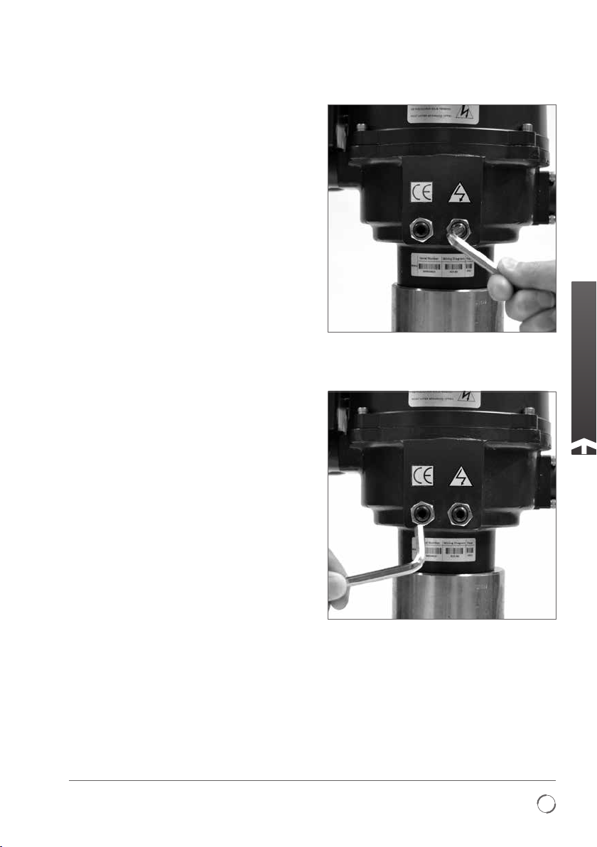
Setting the actuator stop bolts
Stop Bolts
There are no stop bolts fitted in the ROM 1,A.
Adjusting the stop bolts in and out will increase or
decrease the valve travel. It is recommended that
stop bolt adjustment be carried out by the valve
maker/supplier before the valve is fitted into the
pipe work. Once installed, the valve maker/supplier
should be consulted before stop bolt re-adjustment
is carried out. After resetting the stop bolts the limit
switches must be reset. The stop bolts are factory
set to give a nominal 90º travel. If fitted the stop
bolts are located near the gearbox base. Stop bolt
adjustment allows variation at each end position.
Screwing the bolt in reduces movement, out
increases movement.
For clockwise closing valves the right hand stop
bolt is the closed stop. The left is the open stop as
shown in the picture.
Adjustment for non-seating valve types
For closed and open stop position adjustments.
Undo stop bolt lock-nut. Move actuator and valve to
the required stopping position (it may be necessary
to unscrew stop bolt to allow more travel). Screw
stop bolt in until a stop is felt. Tighten stop bolt
lock nut.
Adjustment for seating valve types
For closed and open stop position adjustments.
Undo stop bolt lock-nut. Move actuator and valve
to the required seating position of the valve (it may
be necessary to unscrew stop bolt to allow more
travel). Screw stop bolt in until a stop is felt then
back off by two turns. Tighten stop bolt lock nut
Setting clockwise to close stop bolt
Setting anti-clock to close stop bolt
Redefining Flow Control
5
Page 6

Cable connections
WARNING: Ensure all power supplies are
isolated before removing actuator covers.
Check that the supply voltage agrees with that
stamped on actuator nameplate. A switch or circuit
breaker must be included in the wiring installation
of the actuator. The switch or circuit breaker must
be installed as close as possible to the actuator and
shall be marked that it is the disconnecting device
for that particular actuator. The actuator must be
protected with overcurrent protection devices rated
in accordance with Rotork publication PUB008-001.
Remove red plastic transit plugs. Make cable entries
appropriate to the cable type and size. Ensure that
threaded adaptors, cable glands or conduit are tight
and fully waterproof. Seal unused cable entries with
a steel or brass threaded plug to ensure it is fully
waterproof.
A lug with a 5 mm diameter hole is cast adjacent
to the conduit entries for the attachment of an
external protective earthing strap by nut and bolt.
Connect the earth wire onto the protective earth
screw marked PE located under the actuator
removable cover.
Refer to the wiring diagram to identify functions of
terminals and terminal idents. Ensure exposed wire
conductor is fully inserted into terminal strip.
6
Page 7

Operating by hand
ROM 1/A
On the base of the gearbox a drive is provided for
manual operation. A suitable tool can be located
onto the Hex input drive (8 mm) and rotated in the
appropriate direction to operate the actuator output
This tool is NOT provided.
drive.
WARNING: Ensure the unit is electrically
isolated before manual operation as the input
drive rotates when electrically operated.
ROM 2, 3, 4, 5, 6
The hand wheel is permanently engaged and
rotation of the hand wheel will operate the valve.
The mechanism will automatically disengage when
the actuator is operated electrically.
CAUTION: With respect to handwheel
operation of Rotork electric actuators, under
no circumstances should any additional lever
device such as a wheel key or wrench be
applied to develop more force when closing or
opening the valve as this may cause damage to
the valve and/or actuator to become stuck in
the seated/backseated position.
Local Indicator
On the top cover a continuous position indicator will
rotate and change colour to indicate valve position.
Green is closed, Red is open.
If adjustment of the local indicator is required,
remove the cover and locate the indicator disc.
Loosen screw in the centre of the disc, then rotate
to the new position. Tighten screw and replace
the cover.
Redefining Flow Control
7
Page 8

Commissioning
CAUTION: Before the actuator is electrically
rated ensure the travels cams and limit
ope
switches are correctly adjusted. Refer to travel
cam and limit adjustment.
CAUTION: Before a three-phase supply
actuator is operated for the first time manually
operate the actuator to a mid travel position to
ensure phase rotation is correct.
Travel Cam & Limit Switches
Adjustment
The travel cams are set to control the open and closed
position of the valve. The position is set to stop the
travel of the actuator when the travel cams activate the
limit switch. Standard is two limit switches (LS1 and
LS2), one for open, one for closed.
LS1 & LS2 limit the maximum range by disabling the
electric motor. LS3 & LS4 are optional. They allow
external equipment to confirm that the valve has
reached the fully open and fully closed positions. The
travel cams are preset at the factory, when additional
adjustments are needed, follow items described below.
•
For plastic cam (as shown in picture A), refer to
‘Type 1 - Cam adjustment for plastic cam’ on
page 9 to adjust Cam.
• For metal cam of ROM 1/A (as shown in picture B),
refer to ‘Type 2 - Cam adjustment for ROM1/A’
page 10
on
• For metal cam (as shown in picture C), refer to
‘Type 3-cam adjustment for metal cam‘ on
page 11
to adjust Cam.
to adjust Cam.
LS4
LS3
LS2
LS1
LS4
LS3
LS2
LS1
TC4
TC3
TC2
TC1
Picture A
TC4
TC3
TC2
TC1
Picture B
For ROM 1-6, the rotation direction of output shaft is
identical with position indicator shaft.
LS4: Clockwise end of travel indication
LS3: Anti-clockwise end of travel indication
LS2: Clockwise end of travel
LS1: Anti-clockwise end of travel
For ROM A, the rotation direction of output shaft
is reverse with position indicator shaft. The rotation
direction described below is the same as position
indicator shaft.
LS4: Anti-clockwise end of travel indication
LS3: Clockwise end of travel indication
LS2: Anti-clockwise end of travel
LS1: Clockwise end of travel
Caution: Ensure all power supplies are isolated
before removing actuator covers.
8
LS4
LS3
LS2
LS1
TC4
TC3
TC2
TC1
Picture C
Page 9

Commissioning
Type 1 - Cam adjustment for plastic cam
For Clockwise to close valve
To set the open position:
a. Turn power off.
b. Use manual override to turn valve to the fully
open position.
c. Remove cover.
d. Locate travel cam 1 (TC1). Lifting the cam
against the spring will allow the cam to rotate.
e. Rotate cam anti-clockwise* until switch
operates. Note: it may be necessary to rotate
cam clockwise
f. When switch operates release cam.
g. Open limit switch is now set.
* Clockwise for ROM A
+
Anti-clockwise for ROM A
To set the close position:
a. Turn power off.
b. Use manual override to turn valve to the fully
closed position.
c. Remove cover.
d. Locate travel cam 2 (TC2). Depressing the cam
against the spring will allow the cam to rotate.
e. Rotate cam clockwise* until switch operates.
Note: it may be necessary to rotate cam counter
clockwise
f. When switch operates release cam.
g. Close limit switch is now set.
* Anti-clockwise for ROM A
+
Clockwise for ROM A
For Anti-clockwise to close valves
The indicator flag can be rotated 90º by removing
the actuator cover and loosening the locking screw
on the end of the indicator shaft.
The counter clockwise setting procedure is exactly
the same but the function of LS1 and LS2 will
be reversed. Refer to wiring diagram to identify
function of terminals.
Torque Switches
Optional extra torque switches can be provided
for all sizes except ROM 1/A. Torque switches are
factory set and should not be adjusted.
+
first to release switch.
+
first to release switch.
ROM 1/A
ROM 2, 3, 4, 5, 6
Redefining Flow Control
9
Page 10

Commissioning
Type 2 - Cam adjustment for ROM 1/A
The following instruction is only applicable to
situation that the valve is clockwise for closing
(from the top view).
a. Turn power off.
b. Remove cover and unscrew the self-locking nut
anticlockwise twice approximately 60 degree
each time from position A to B as shown in
picture D by inserting 4.0mm Allen key into the
hole of self-locking nut.
Note: the Allen key should be flat head and
longer than 100mm.
c. Set fully open position by following item
1, 2, 3 below.
1. Use manual override to turn valve to the
fully open position.
2. Make sure the roller of LS1 is touching
the cylindrical surface of TC1.
Case 1: For ROM 1, rotate TC1 anti-clockwise
3.
slowly until a light click is heard.
Case 2: For ROM A, rotate TC1 clockwise
slowly until a light click is heard.
d. Set fully closed position by following item
1, 2, 3 below:
1. Use manual override to turn valve to the
fully closed position.
2. Make sure the roller of LS2 is touching the
cylindrical surface of TC2.
3. Case 1: For ROM 1, rotate TC2 clockwise
slowly until a light click is heard.
Case 2: For ROM A, rotate TC2
anti-clockwise slowly until a light click
is heard.
e. Screw the self-locking nut clockwise to original
position (approximately twice 60 degree ).
f. Apply power to check the travelling position, if
the position is not correct, please repeat steps
a - f.
B
A
Picture D: Travel from position A to B is about
60 degree
ROM 1/A
TC: Travel Cam
LS: Limit Switch
TC1: “OPEN”
Clockwise
ROM 1: Increase opening degree to fully open
ROM A: Decrease opening degree
Anti-clockwise
ROM 1: Decrease opening degree
ROM A: Increase opening degree to fully open
TC2: “CLOSE”
Clockwise
ROM 1: Decrease closing degree
ROM A: Increase closing degree to fully closed
Anti-clockwise
ROM 1: Increase closing degree to fully closed
ROM A: Decrease closing degree
TC3: Synchronous turn with TC1 (optional)
TC4: Synchronous turn with TC2 (optional)
10
Page 11

Commissioning
Type 3 - Cam adjustment for metal cam
The following instruction is only applicable to
situation that the valve is clockwise for closing
(from the top view).
To set the Open position:
a. Turn power off.
b. Use manual override to turn valve to the fully
open position.
c. Remove cover and loosen the TC1 set screw
using a 2.5 mm Allen key.
d. Case 1: If the roller of LS1 is touching
the cylindrical surface of TC1, rotate TC1
anti-clockwise* slowly until a light click
is heard.
Case 2: If the roller of LS1 is touching the flat
surface of TC1, firstly rotate TC1 clockwise
+
slowly until the roller of LS1 is touching the
cylindrical surface of TC1, then repeat Case 1.
e. Securely tighten the TC1 set screw and apply
power to check the travelling position. If the
position is not correct, please repeat steps a - e.
f. Open position is now set.
* Clockwise for ROM A
+
Anti-clockwise for ROM A
To set the Close position:
a. Turn power off.
b. Use manual override to turn valve to the fully
closed position.
c. Remove cover and loosen the TC2 set screw
using a 2.5 mm Allen key.
d. Case 1: If the roller of LS2 is touching
the cylindrical surface of TC2, rotate TC2
clockwise* slowly until a light click is heard.
Case 2: If the roller of LS2 is touching the flat
surface of TC2, firstly rotate TC2 anti-clockwise
slowly until the roller of LS2 is touching the
cylindrical surface of TC2, then repeat Case 1.
e. Securely tighten the TC2 set screw and apply
power to check the travelling position. If the
position is not correct, please repeat steps a - e.
f. Close position is now set.
* Anti-clockwise for ROM A
+
Clockwise for ROM A
ROM A and ROM 1-6
TC: Travel Cam
LS: Limit Switch
TC1: “OPEN”
Clockwise
ROM 1-6: Increase opening degree to fully open
ROM A: Decrease opening degree
Anti-clockwise
ROM 1-6: Decrease opening degree
ROM A: Increase opening degree to fully open
TC2: “CLOSE”
Clockwise
+
ROM 1-6: Decrease closing degree
ROM A: Increase closing degree to fully closed
Anti-clockwise
ROM 1-6: Increase closing degree to fully closed
ROM A: Decrease closing degree
TC3: Synchronous turn with TC1 (optional)
TC4: Synchronous turn with TC2 (optional)
Redefining Flow Control
11
Page 12

Commissioning
Potentiometer adjustment (if fitted)
The potentiometer is factory set to operate over 90
degrees and should not require adjustment. It may
be necessary to adjust the potentiometer if the stop
bolts have been adjusted or the POT has slipped out
of range.
Move the valve to the fully closed position and
ensure the stop bolts are correctly set.
Note there are no stop bolts in ROM 1/A.
Remove the potentiometer mounting screws to
release the drive gear and rotate the gear so that a
nominal 50 Ohms resistance pot value is measured
across terminals 10 and 11.
Replace the pot assembly ensuring the gears are
engaged and mounting screws are tight.
12
Page 13

Troubleshooting
Conditions Possibilities Solutions
Motor does not operate. 1. Is the power and voltage supply correct? 1. Check supply.
Motor stops running. 1. Obstructed valve? 1. Check valve operation.
Unable to fully
open / close.
Motor overheats.
Actuator operates but
no valve moment.
Actuator runs in
wrong direction.
Erratic operation of
multiple actuators.
1. Cams not set correctly?
2. Bent valve stem?
3. Stop bolt adjustment incorrect?
1. Is the voltage correct?
2. Is the valve too tight for operation?
3. High working frequency?
1. Drive adaptor worn?
2. Broken valve stem?
1. Wrong terminals connected?
1. Wrong 3-phase wiring?
1. Multiple actuators on the same
control circuit.
1. Adjust cams.
2. Investigate valve.
3. Reset stop bolts.
1. Check voltage.
2. Investigate valve.
3. Check duty-cycle.
1. Replace adaptor.
2. Investigate valve
1. Check remote control circuit.
1. Change phase wiring.
1. Actuators must have individual
control circuit.
Redefining Flow Control
13
Page 14

Wiring Diagram
ROM 1/A, 2, 3, 4, 5, 6
14
Page 15

Notes
Redefining Flow Control
15
Page 16

Redefining Flow Control
CHECK IF THE MAP
NEEDS UPDATING
CHECK PUBLICATION
NUMBER IS CORRECT
www.rotork.com
A full listing of our worldwide sales and
service network is available on our website.
UK
Rotork plc
tel +44 (0)1225 733200
fax +44 (0)1225 333467
email mail@rotork.com
PUB008-005-00
Issue 03/15
USA
Rotork Controls Inc.
tel +1 (585) 247 2304
fax +1 (585) 247 2308
email info@rotork.com
As par t of a process of o n-goi ng produc t developm ent, Rotork re serve s the right to
amend and ch ange speci ficatio ns without pr ior notice. P ublished da ta may be subj ect
to change. Fo r the very la test versi on releas e, visit our web site at ww w.rotork.com
The name Rot ork is a regis tered trade mark. Rotork recognise s all registe red tradem arks.
Publishe d and produce d in the UK by Roto rk Controls Li mited. POW SH0315
 Loading...