

Page 1
Publication S177E V2.0 Issue 03/05
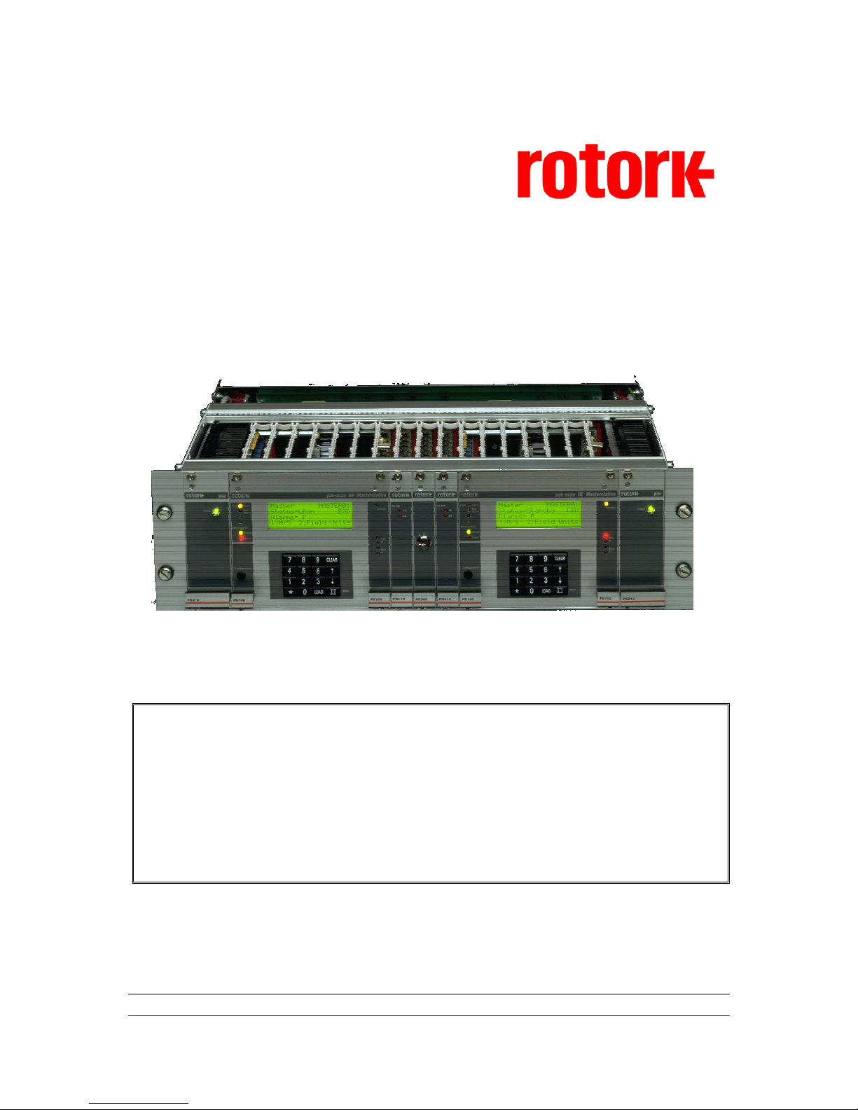
Pakscan IIE Master Station
System Manual
Page 2

Pakscan IIE System Manual
2 of 132 Publication S177E V2.0 Issue 03/05
As we are continually developing our products their design is subject to change without notice.
© The contents of this document are copyright and must not be reproduced without the written
permission of Rotork Controls Ltd.
The name Rotork is a registered trademark
Windows is a registered trademark by Microsoft Corporation
Modbus is a registered trademark by Modbus IDA
Software Level
This manual relates to Pakscan IIE master stations fitted with software
versions
V25 (5206-014) software version 5.8 or greater
Loop Driver (5206-034) software version 5.2 or greater
Page 3

Contents
3 of 132 Publication S177E V2.0 Issue 12/04
Contents
Glossary of Terms...........................................................................................................................7
Abbreviations ..................................................................................................................................7
How to use this Manual ..................................................................................................................9
Software level ..................................................................................................................................9
1 INTRODUCTION.................................................................................................11
1.1 Related Documents..............................................................................................................11
2 EQUIPMENT DESCRIPTION..............................................................................13
3 STORAGE PROCEDURE...................................................................................15
4 OVERVIEW OF PAKSCAN.................................................................................17
4.1 Field Control Units...............................................................................................................17
4.2 Control and Indication.........................................................................................................18
5 FUNCTIONS........................................................................................................19
5.1 Cable Fault Protection - Loopback system.......................................................................19
5.2 Current Loop Start Up Operations.....................................................................................19
5.2.1 Loop Configuration ..................................................................................................20
5.2.2 Normal Running Operation......................................................................................20
5.3 Modbus Serial and Ethernet Interfaces .............................................................................21
5.4 Local User Interface (LCD and Keypad) ............................................................................21
6 INITIAL SETTING UP..........................................................................................23
6.1 Jumper Settings...................................................................................................................23
6.2 External Links.......................................................................................................................25
6.3 Display Screen Contrast .....................................................................................................26
7 INSTALLATION AND CONNECTION.................................................................27
7.1 Mounting...............................................................................................................................27
7.2 Mains Power .........................................................................................................................27
7.3 Field Wiring...........................................................................................................................28
7.3.1 Screen Connections ................................................................................................29
7.4 Loop Checks.........................................................................................................................29
7.4.1 Loop Continuity........................................................................................................29
7.4.2 Screen Continuity ....................................................................................................30
7.4.3 Cable Capacitance ..................................................................................................30
Page 4

Pakscan IIE System Manual
4 of 132 Publication S177E V2.0 Issue 03/05
8 LOCAL USER INTERFACE................................................................................33
8.1 Front Panel Indication LEDs...............................................................................................33
8.2 LCD Screen and Keypad.....................................................................................................34
8.3 Keypad Security...................................................................................................................35
8.3.1 Using a PIN..............................................................................................................35
8.4 Menu Structure.....................................................................................................................35
8.5 Master Station Status ..........................................................................................................38
8.5.1 Master Station Commands......................................................................................39
8.5.2 Master Station Alarms - Text Description................................................................40
8.6 Configuration Mode Screen................................................................................................41
8.7 Diagnostic Menus ................................................................................................................42
8.7.1 Top Diagnostic Display............................................................................................42
8.7.2 Modbus Port Diagnostic Displays............................................................................43
8.7.3 Printer port diagnostic display .................................................................................44
8.7.4 Loop Diagnostic Display..........................................................................................45
8.7.4.1 FCU Map and Failure Counts ..................................................................47
8.7.4.2 Loop Speed Test......................................................................................48
8.7.4.3 FCU Address Fault Details.......................................................................49
8.7.5 Hot Standby Inter Unit Diagnostic Display...............................................................50
8.8 Setup Menus.........................................................................................................................51
8.8.1 Top Setup Menu......................................................................................................51
8.8.2 Port Setup Menus....................................................................................................52
8.8.2.1 Alarm Linkage ..........................................................................................53
8.8.3 Data transfer to Standby Unit ..................................................................................54
8.8.4 Loop Setup Menu ....................................................................................................55
8.8.4.1 Further Loop Options ...............................................................................56
8.8.5 Unit Address Setup Menu........................................................................................57
8.8.6 Tag Setup Menu......................................................................................................58
8.8.7 Date and Time Setup...............................................................................................59
8.8.8 ESD Options Setup Menu .......................................................................................60
8.8.9 Keypad Security Options.........................................................................................61
8.9 Field Unit Menus ..................................................................................................................62
8.9.1 Actuator Field Unit Status Display...........................................................................62
8.9.1.1 IQ Actuator Second Status Page .............................................................63
8.9.1.2 IQ and IQT Historic Torque Displays .......................................................64
8.9.2 Flowpak Actuator Field Unit Status Display.............................................................65
8.9.3 General Purpose Field Unit Status Display.............................................................66
8.9.3.1 Second Page for General Purpose Field Unit..........................................67
8.9.4 IQ Analogue Input Field Unit ...................................................................................68
8.9.5 Communications Failure Display.............................................................................69
8.9.6 Field Unit Status Secondary Data ...........................................................................70
8.9.7 Field Unit Alarm – Text Description.........................................................................71
9 SETTING PARAMETERS...................................................................................73
9.1 Initial Decisions....................................................................................................................73
9.2 Serial Communication Ports...............................................................................................74
9.3 Loop Data..............................................................................................................................75
Page 5

Contents
5 of 132 Publication S177E V2.0 Issue 12/04
9.4 Tag Names............................................................................................................................76
9.5 Date and Time.......................................................................................................................76
9.6 ESD Configuration...............................................................................................................77
9.7 Security Access Level.........................................................................................................77
9.8 Final Checks.........................................................................................................................77
10 SETTING A HOT STANDBY PAIR PARAMETERS...........................................79
10.1 Copy Data A to B..................................................................................................................79
10.2 Changes to Terminal Connections.....................................................................................79
10.2.1 Main/Standby Connections......................................................................................79
10.3 Hot Standby Parameter Setting and Options....................................................................81
10.4 The PS300 Keyswitch ..........................................................................................................81
11 INCLUDING A PS410 CONVERTER..................................................................83
11.1 Jumper functions.................................................................................................................84
11.1.1 PS410 port 2 to RS485 setup..................................................................................84
11.1.2 PS410 port 1 to RS232 setup.................................................................................85
11.1.3 LED functions ..........................................................................................................85
11.1.4 RS485 line conditioning...........................................................................................85
11.1.5 2-Wire and 4-wire RS485 communications.............................................................86
12 SETTING UP AND USING THE PS600 ETHERNET MODULE .........................87
12.1 Internal Connections ...........................................................................................................88
12.2 Connecting to the Ethernet Bridge ....................................................................................88
12.2.1 Local Ethernet Connection ......................................................................................89
12.2.2 Direct Ethernet Connection to a PC ........................................................................89
12.2.2.1 Connection using Windows XP................................................................89
12.3 Ethernet Module Status Indicators.....................................................................................90
12.3.1 LED Functionality.....................................................................................................90
12.4 Setting Up the Module .........................................................................................................91
12.4.1 Setting the Serial Connection Fields .......................................................................92
12.4.2 Setting the User Fields for the Web Browser ..........................................................93
12.4.3 Setting the Alarm Messaging Information................................................................95
12.4.4 Setting the Local Area Network Connection Parameters........................................96
12.5 Using the Ethernet Connection ..........................................................................................97
12.5.1 Master Station Overview .........................................................................................97
12.5.2 Master Station Configuration...................................................................................98
12.5.3 Network Diagnostics................................................................................................99
12.5.4 FCU Menu ............................................................................................................ 100
12.5.4.1 Field Unit Status and Control................................................................ 101
12.5.4.2 Field Unit Alarms screen....................................................................... 102
12.5.4.3 IQ and IQT Actuator Torque screen...................................................... 102
12.5.5 FCU Parameters................................................................................................... 103
13 COMMISSIONING THE SYSTEM.....................................................................107
Page 6

Pakscan IIE System Manual
6 of 132 Publication S177E V2.0 Issue 03/05
13.1 Checking Individual Field Units....................................................................................... 107
13.2 Checking the Loop Itself .................................................................................................. 108
13.3 Checking System Performance....................................................................................... 110
13.3.1 Setting the Loop Driver Voltages.......................................................................... 110
13.4 Diagnostic Information..................................................................................................... 111
13.4.1 Loop Configuration ............................................................................................... 111
13.4.2 Loop Communications.......................................................................................... 112
13.4.3 Loop speed reprogramming ................................................................................. 112
13.4.4 Checking Host Communications .......................................................................... 113
13.5 Final Checks...................................................................................................................... 113
13.6 Commissioning Aids ........................................................................................................ 114
14 MASTER STATION SOFTWARE VERSION ....................................................115
15 SET UP DATA RECORDS................................................................................ 117
15.1 Loop Map ........................................................................................................................... 118
16 TECHNICAL SPECIFICATIONS.......................................................................121
16.1 Master Station ................................................................................................................... 121
16.2 Actuator Field Units.......................................................................................................... 121
16.3 GP Field Unit...................................................................................................................... 122
16.4 2-Wire Loop ....................................................................................................................... 122
16.5 External Connections ....................................................................................................... 124
16.5.1 Loop Connections and Digital I/O......................................................................... 124
16.5.2 Serial Ports ........................................................................................................... 125
16.6 Printer Messages .............................................................................................................. 127
16.7 Maintenance ...................................................................................................................... 127
16.8 Master Station Dimensions.............................................................................................. 128
17 GENERAL SAFETY INFORMATION................................................................129
Page 7

Contents
7 of 132 Publication S177E V2.0 Issue 12/04
Glossary of Terms
Address The unique address for a field unit on the Pakscan loop, range 1-240
Loop The digital, twisted pair 2-wire data communication link
Field Unit The Pakscan option card fitted to the actuator, or complete General Purpose field
unit
Master/Slave The method of communication used on the field loop. The master station controls
the data exchange on the highway
Node A single device (address) on the Pakscan loop
RS485 The electrical properties as defined by the IEA485 standard, 2-wire twisted pair.
RS232 The electrical properties as defined by the IEA232 standard
Abbreviations
Comms Communications
FCU Pakscan Field Unit
RAM Random Access Memory
ROM Read Only Memory
RTU Remote Terminal Unit
SW Software
Page 8

Pakscan IIE System Manual
8 of 132 Publication S177E V2.0 Issue 03/05
Page 9

Contents
9 of 132 Publication S177E V2.0 Issue 12/04
How to use this Manual
In order to make the best use of the information in the following pages we suggest you use this
manual as follows:
Familiarise yourself with the hardware - section 4 will show you all the parts
Read sections 4 to 12 before attempting to commission the system
Refer to section 6 to check the internal link settings
Section 8 relates to the front panel LED’s, keypad and LCD screen
Make sure you understand how to connect the system - section 7 tells you how
Set up the Software selected parameters - also see section 9
With a Hot Standby system check the information in section 10
Commissioning the system is explained in section 13
If you have RS485 Converter units, read section 11 carefully
Ethernet connections are explained in section 12
Record the information about your system on data sheets such as those outlined in section
15, or use Rotork MasterTools to document the system. Pakscan Ethernet systems can
also record the master station data to file from the web server application.
Software level
This technical manual relates to Pakscan IIE master stations with software version 5206-014 V5.8 or
later for the main V25 processor and version 5206-034 V5.2 or later for the loop processor.
MasterTools
The software utility, MasterTools, runs on a PC and maybe downloaded from www.rotork.com.
With this utility a complete record of the Pakscan loop, the field units and master station settings
can be made and retained either as an electronic file or the data may be printed out.
Page 10

Pakscan IIE System Manual
10 of 132 Publication S177E V2.0 Issue 03/05
(This page is intentionally blank)
Page 11

Introduction
11 of 132 Publication S177E V2.0 Issue 03/05
1 INTRODUCTION
This document describes the procedures for setting up commissioning and running a Pakscan IIE
system. If the unit is to be stored for a period of time prior to its use, then please refer to section 3 for
information about storage of electronic equipment.
The Pakscan IIE master station hardware is a stand-alone unit requiring only the connection of power
and suitable field units to operate. This manual describes the Pakscan IIE master station only. Please
refer to the documentation relating to the field units for information on that part of the system.
The Pakscan IIE system is compatible with all Pakscan II and IIE field units and setting tools. The
Pakscan IIE is equipped with either serial communication ports, or Ethernet ports, or both through
which the master station can be controlled and operated from another device. The communication
protocol supported by these ports is Modbus RTU and Modbus TCP and details of the function codes
and data base organisation established within the master station are contained in the associated
protocol documents.
1.1 Related Documents
There are a number of documents for the Pakscan system that relate to the Pakscan IIE master
station these include:
General
(1) Field Test Unit Technical Manual (Paktester) S178E
(2) Master Station Test Unit Technical Manual (Pakreader) 5161-021
(3) Pakscan IIE RS485 Converter Technical Manual 5218-023
Serial Communications
(4) Pakscan Modbus Interface Specification S171E
Page 12

Pakscan IIE System Manual
12 of 132 Publication S177E V2.0 Issue 03/05
(This page is intentionally blank)
Page 13

Equipment Description
13 of 132 Publication S177E V2.0 Issue 03/05
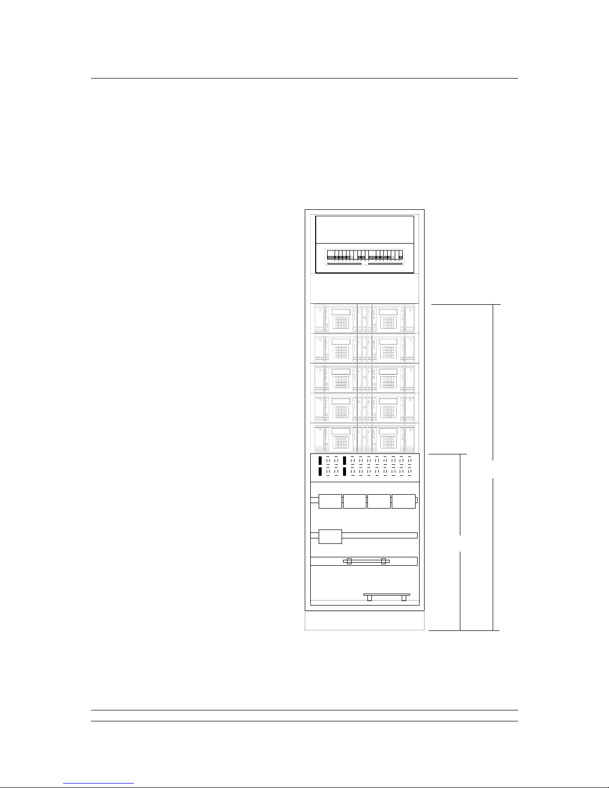
2 EQUIPMENT DESCRIPTION
The master station is an assembly of a computer card, a current loop interface card, a power supply
card, and a front panel with an LCD screen and 16-key keyboard, fitted to a standard 19-inch rack.
The rack will contain some or all of the items identified in Fig. 1.
PS100 CPU and Display Module (two off in Hot Standby systems)
PS210 Power Supply module (unless the hardware is supplied by 24V dc)
PS300 Switch module for Hot Standby systems only
PS410 RS485 Converter (optional)
PS601/2/3/4 Ethernet port converter
The rack can accommodate two master stations, when viewed from the front these are referred to as
M/S A on the left and M/S B on the right. The 19-inch rack is always fully wired to accommodate all
variations of assembly within it. Some applications may require external links on the connectors and
terminal blocks and these will normally be fitted before despatch. It is advisable to check that any links
that may be required for a particular application are in place. When PS601 or PS602 Ethernet servers
are fitted there will be links to the Port 1 or Port 2 connectors and these will not be available for host
connections.
All master stations have their own dedicated power packs, each operating from an independent input.
In the case of a dual or hot standby system there maybe two independent supplies to the rack.
Optional additional cards may be fitted to the master station rack for converting the communications
hardware between RS232 and RS485, and in the case of a Hot Standby a switch unit is also included.
If the master station includes Ethernet connectivity then there are internal servers fitted inside the
rack. Where no cards are fitted blanking plates are used to cover the resulting space.
Two master stations may optionally be interconnected to form a dual redundant system. In this
configuration, one unit controls the loop, whilst the other acts as a 'hot standby'. Changeover between
the units can be automatic or manually triggered.
MASTER STATION A MASTER STATION B
PS210 - Power Supply
PS100 - CPU & Display Module
PS410 - RS232/RS485 Converter
PS300 - Keyswitch
PS60X - Ethernet Server (Internal)
Fig 1: Pakscan IIE Master Stations in a 19 inch rack
Page 14

Pakscan IIE System Manual
14 of 132 Publication S177E V2.0 Issue 03/05
On the rear are the following items, repeated for both M/S A and M/S B.
Power Connector (IEC) for use with a.c. powered units (when a 24V dc supply is used this
is replaced by a terminal block). There is a 1 Amp slow blow fuse adjacent to the power
connection.
26 screw terminals for Field Connections, of these 25 only are used, and terminals 1 to 21
are directly linked internally to the 25 way D type connector (pins 1 to 21) above the
terminal block.
Two 9 way D type connectors for Comms Port 1, a male and a female. This port is always
RS485, 2-wire.
A single 9 way D type female connector for Comms Port 2. This port is always RS232.
There are two further connectors, 9 way D type female, for Ports 3 and 4. These are only
used if the optional RS232/485 Protocol Converter Module, PS410, is fitted, as described in
section 11.
One trailing RJ45 female socket for connection to the Ethernet server when one is fitted.
For host computer communications either serial or Ethernet connections can be used. The data format
for information exchange is Modbus RTU (for serial ports) or Modbus-TCP (for Ethernet LAN
connection). There are multiple data bases within the master station and these are explained later in
this manual.
Support for a printer to log alarms is provided. Each entry can be tagged with the time and date. There
are contact outputs for various alarm conditions, and provision for an Emergency Shutdown (' ESD')
input. Emergency Shutdown may be invoked by breaking the circuit between two terminals at the
master station causing an 'ESD' message to be broadcast on the current loop. Field units and
actuators may be set up to carry out an appropriate action, e.g. close a valve.
Fig 2: Pakscan IIE Master Stations – rear view
PORT 1
RS485
PORT 2
RS232
FIELD CONNECTIONS
PORT 3
PORT 4
RS485
PORT
EXP
PORT 3
PORT 4
RS485
PORT
EXP
PORT 1
RS485
PORT 2
RS232
FIELD CONNECTIONS
MAINS INPUT
90 - 264 Vac
FUSE 1A
MAINS INPUT
90 - 264 Vac
FUSE 1A
MASTER STATION B MASTER STATION A
Data Label
Field Terminals and D-type Connector
Comms Port 1 (2xD-type)
Comms Port 2 (D-type)
Ethernet (RJ45)
IEC Power Connector
Page 15

Storage
15 of 132 Publication S177E V2.0 Issue 03/05
3 STORAGE PROCEDURE
On receipt the hardware should be examined for signs of damage and to ensure that the expected
equipment is present. Identify all the parts.
If the unit is to be stored for a period of time then normal conditions for keeping electronic hardware
must be provided.
The ambient conditions should remain in the following bands at all times:
Temperature: 10 - 30 degrees Centigrade
Humidity: Not to exceed 80% R.H.
The equipment should not be stacked, though it may be stored in any orientation. The original packing
should be retained. DO NOT LOSE THE MANUALS.
If it is to be kept for a prolonged period then an electrical exercise test is recommended every 6
months, for 24 hours. The master station internal battery has a shelf life of 3 years.
Page 16

Pakscan IIE System Manual
16 of 132 Publication S177E V2.0 Issue 03/05
(This page is intentionally blank)
Page 17
Pakscan Overview
17 of 132 Publication S177E V2.0 Issue 03/05
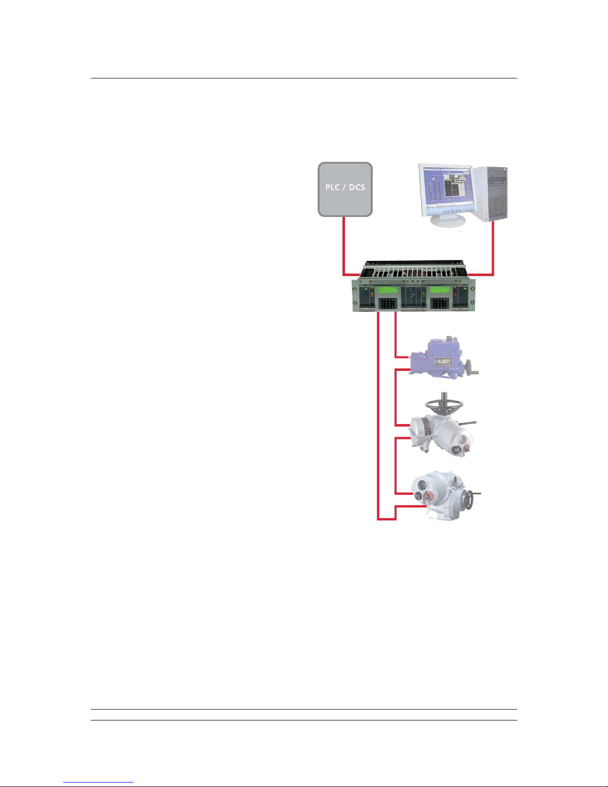
4 OVERVIEW OF PAKSCAN
The Pakscan system is a control and monitoring
package comprising a master station, 2-wire serial
data cable wired in a ring or loop and a number of
connected actuators with Pakscan field units fitted.
The fieldbus loop can have up to 60, 120, 180 or
240 field units connected depending on the
capability of the master station, and the cable can
be up to 20 km long. The length of the 2-wire cable
(loop length) can be considered as the
circumference of a circle starting and finishing at
the master station.
The master station is a single module in a 19-inch
rack. It may have a supporting, identical, standby
unit. Details of setting a Hot Standby pair are
covered in Section 10. In essence, the Hot Standby
simply comprises two identical master stations each
of which is set identically to its partner. In some
cases two master stations are fitted into one 19inch rack (there is space for two). These can be
considered as two independent units.
The current loop is single fault tolerant and can
withstand either an open circuit, short circuit or
ground connection fault and still maintain
communication with all the field units. Subsequent
faults do not stop the complete system from
working and the parts that remain connected to the
master station will continue to be in communication
with it.
In addition to controlling the loop, the master station
also provides the external interface to the system.
It supports 2 serial ports for communications to host
computers, as well as providing a local user
interface. Alternatively, one of the serial ports may
be used to drive a printer to log alarms. In the
Pakscan Ethernet version one or both the serial ports are replaced with a standard 10Base-T Ethernet
ports. When a single Ethernet port is available the remaining serial port may be either RS232 or
RS485 depending on the option chosen.
4.1 Field Control Units
A range of field control units ('FCU’s') is available to cater for specific application areas. These may be
summarised as follows:
Fig 3: Pakscan IIE System Diagram
Page 18

Pakscan IIE System Manual
18 of 132 Publication S177E V2.0 Issue 03/05
Integral type field control units mounted within a Rotork actuator electrical housing such
as the IQ, IQT or Q range actuator.
Externally mounted field control unit. Various packages are available, including 'Pakbox',
weather-proof box, or rack mounting. The unit may be used for either actuator control
applications, or for general purpose applications such as pumps, blenders etc. Its
complement of I/O is 8 digital inputs, 4 changeover relay outputs, 2 analogue inputs and
1 analogue output.
4.2 Control and Indication
The field units each report information to the master station that can be viewed on the integral LCD
display, or collected from the serial communication port of the master station for use on another
display system. The reported data is already organised and requires no configuration by the user;
each field unit automatically reports all its available data.
Commands to operate the output devices may be sent over the system, the initiation of the command
can either be from the integral keypad (under the correct access code) or from the serial or Ethernet
data link. Once again the organisation of these commands is already configured and the user only has
to address the correct register to implement the command.
Page 19

Functions
19 of 132 Publication S177E V2.0 Issue 03/05
5 FUNCTIONS
5.1 Cable Fault Protection - Loopback system
Communication between the master station and the field control units is via a twisted pair 2-wire cable
carrying a 20 mA current in a loop. In normal operation the current flows round the loop on one wire
and returns via the master station on the second wire. If high-speed operation with ‘doubling on’ is
selected the current returns inside the master station and the second wire is not used.
Each field control unit has the capability to connect the 2 wires together (apply a loopback circuit), and
this mechanism is used to divert the current in the event of a loop fault. With field units each side of a
loop fault 'in loopback', the system can still communicate with all field units by operating the system as
2 segments. If there are 2 loop faults, those field units between the faults will be isolated.
A loop cable fault may be an open circuit, a short circuit, or an earth fault.
5.2 Current Loop Start Up Operations
The Pakscan IIE controls the current on the loop to communicate with the attached field units. Loop
communication divides into two parts: configuration (when the master station decides whether the loop
is complete, and if not, where the faults are), and normal operation.
Fig 4: Loopback system
Master Station
Port B
Port A
Add 2
Add 4
Add 3
Add 1
In OutOutIn
Master Station
Port B
Port A
Add 2
Add 4
Add 3
Add 1
In OutOutIn
Normal operation Broken loop operation
Cable
Fault
LB on LB on
Page 20

Pakscan IIE System Manual
20 of 132 Publication S177E V2.0 Issue 03/05
5.2.1 Loop Configuration
The loop configuration phase is entered after power-up, after a loop fault is detected, or after a loop
configure command is received.
Configuration consists of the following steps:
1. Wait for all the field units to go into loopback. The time is dependent on the baud rate.
2. Issue a command from Port A to ask a field unit in loopback for its address. This finds the
first field unit.
3. Use that address to tell the field unit to remove its loopback.
4. Repeat steps 2 and 3 until no more field units are found.
5. Attempt to send a message right round the loop and receive it back at the sending end.
This tests the integrity of the complete loop.
6. If the loop is complete stop here. If the loop has a problem execute steps 7 to 10.
7. Repeat steps 2 to 4 from Port B.
8. Again wait for all field units to go into loopback.
9. Remove loopbacks one field unit at a time from Port A until only the last field unit is left in
loopback.
10. Repeat step 9 for Port B.
Loop configuration will identify and mark as out of service any field unit found which has an address
that is zero, an address that is the same as one which has already been found, or which has an
address, which is too high. An address that is too high is one outside the range selected for the master
station.
The master station has the facility to double the loop Baud rate. If this facility is enabled, via the
Keypad, the master station will issue a broadcast command to all the field units to get them to double
the baud rate they are using, once it has detected that the loop is complete.
5.2.2 Normal Running Operation
In normal operation, the master station polls each field unit for any changed data it has to report. Most
of the time, field units have no changes to report, and traffic on the loop is kept to a minimum. Field
units are polled in address order. Data that might be reported includes changes to digital inputs, alarm
changes, or significant changes to an analogue input.
If a field unit, which previously responded on the last scan, fails to respond correctly the master station
will retry twice to get a reply. On subsequent scans only a single attempt is made to get a response.
All field units up to the address preset in the master station database are polled. Thus new field units
which are powered-up on a working loop will be identified by the master station, provided they are
within the selected address range, and future scans will poll the new field unit for data.
Commands to field units (open, close, etc.) are interleaved between polls to individual field units. This
ensures they are sent as soon as a slot is available. When the current transaction is completed the
command will be next.
A check is made at the end of each scan to see if a loop fault has occurred. For a complete loop with
no loopbacks present a test message is sent round the loop; for a broken loop (loopbacks in use)
Page 21

Functions
21 of 132 Publication S177E V2.0 Issue 12/04
communications failure to the last field unit on either side is taken as an indication of a fault. In the
event of a new fault, loop re-configuration is initiated.
5.3 Modbus Serial and Ethernet Interfaces
The Pakscan IIE master station is provided with two interfaces for data exchange with external host
systems. These may be a combination of one serial and one Ethernet, two serial or two Ethernet
connections. In addition one port can be selected for serial printer use. For Ethernet connections one
or more PS601, PS602, PS603 or PS604 modules must be fitted. In all cases the interfaces behave
similarly and always use Modbus RTU or Modbus TCP for the data communication protocol.
The master station's use of the Modbus RTU protocol is described in detail in the protocol documents
listed in section 1 (Related Documents). The master station may operate slightly differing protocols
data bases from each of its two ports. The protocols available are indicated on the set up screen
display, (see screen displays section). Modbus TCP behaves in a similar manner to Modbus RTU and
the register locations are the same for both protocols.
The two serial ports can both issue commands to field units via the master station, and to the master
station itself. Three separate registers of field unit alarms are maintained by the master station, one for
each serial or Ethernet port and one for the front panel display. This ensures that alarms cannot be
missed by any of the interfaces. If the host system is reading alarms from both the serial data bases it
must consider each one separately and perform the read and accept routines for each serial link.
Accepting an alarm on either serial interface does not accept the alarm on the display, or vice versa.
The alarm handling on the Modbus TCP Ethernet link is different. If the host protocol is selected as
Yokogawa then the alarm handling is exactly as for the RTU serial data and alarms are held until
accepted. If the protocol is selected as Generic then the Web Server will be populated with data; alarm
handling is similar to the other serial data bases, but now either the web server or the external
Ethernet host can accept the alarm on the associated data base. Effectively there is one alarm register
for the IP address and both the web server and host access the same register and accept the same
register.
5.4 Local User Interface (LCD and Keypad)
The Local User Interface allows the master station to be interrogated directly for its own status and
diagnostic information, and for field unit status. Various parameters may also be configured from the
front panel and commands sent to field units. The available screens are illustrated later in this manual.
Page 22

Pakscan IIE System Manual
22 of 132 Publication S177E V2.0 Issue 03/05
(This page is intentionally blank)
Page 23

Jumpers and Links
23 of 132 Publication S177E V2.0 Issue 03/05
6 INITIAL SETTING UP
The factory default settings for the jumpers and links inside the master station will be satisfactory for
most applications. However there are some cases where special settings could be required. Before
applying any power to the master station check that the internal settings of the jumpers match the
system requirements. These jumpers will have been factory set to the default positions, or to user
specified positions, prior to dispatch.
In addition to the internal jumpers there may be a need to fit external links to achieve satisfactory
operation of the installed unit, for example with Hot Standby units. These links can be fitted prior to
installation.
6.1 Jumper Settings
The PS100 CPU and Display module contains a number of jumpers to set some of the parameters for
the performance of the unit. These are factory set and should generally not require adjustment at any
time. However there are links that may need to be fitted to match specific applications. There are no
jumper links on the power board, display board or loop driver board that require customer adjustment.
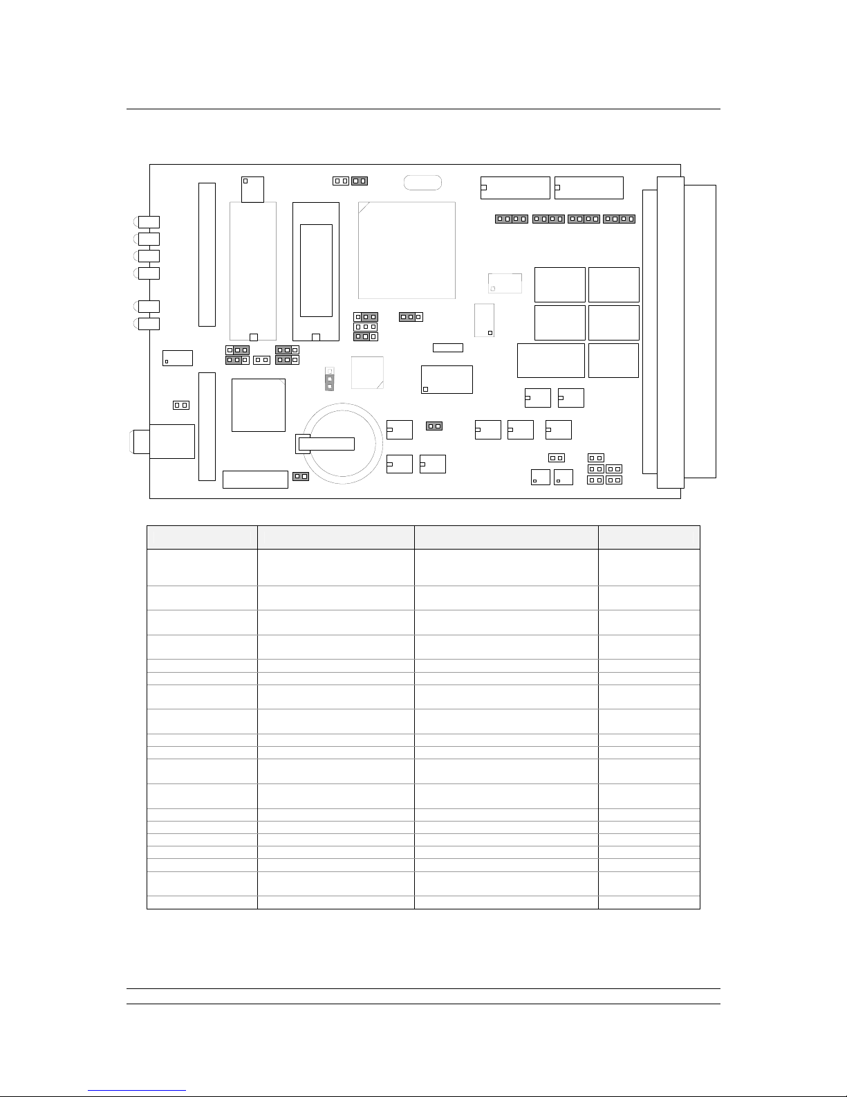
The diagram Fig. 5 is a top view of the PS100 module showing the different circuit boards. Fig. 6
shows the layout of the V25 card of the module. This is the PCB located to the left of the display
screen when viewed from the front; it is clearly distinguished by the battery on the board.
The function and default settings of the jumpers is listed in the table, please note that some select the
type of integrated circuit used, and therefore may vary from one unit to another.
Front Display
V25 CPU
board
Loop Driver
board
Power
board
Display
board
Rear Connectors
Fig 5: The PS100 card positions
Page 24
Pakscan IIE System Manual
24 of 132 Publication S177E V2.0 Issue 03/05
Jumper No Description Function Setting
J1 Reset jumper Normal operation
Override reset
Hold in reset
A
Not fitted
B
J2 RAMWR jumper Normal operation
Full RAM access
Link 1 - 2
Not fitted
J3 CTR CLK2 jumper CTR CLK2 Freq - A
ISAF – B
J4 MEMWR MEMWR Flash - B
EPROM – A
J5 RAM (A12) jumper A12 Fitted
J6 ROM (A17) jumper A17 Fitted
J7 IRQ jumper IRQ enable
IRQ disable
Not fitted
Fitted
J8 CTS jumper CTS enable
CTS disable
Link 1-2
Link 2-3
J10 ROM (A18) jumper A18 Fitted
J11 ROM (A15) jumper A15 Fitted
J12 to J15 Digital input jumpers Un-isolated
Isolate channel
Link 1-2 & 3-4
Link 2-3
J17 & J18 RS485 termination jumpers
J17 = data, J18 = RTS
Termination
No Termination
Fitted
Not fitted
J19 RAM (A16) jumper A16 Fitted
J20 & J25 RS485 bias jumper RS485 bias data Fitted
J21 & J26 RS485 bias jumper RS485 bias RTS Fitted
J24 FPGA write jumper Enable local FPGA write Fitted
J27 CTS1 jumper CTS1 enable (RS485 only) Fitted
J28 Battery jumper Disconnect battery
Connect battery
None
Fitted
J29 INTP2 jumper Enable INTP2 Fitted
Fig 6: Master Station V25 card internal links
J29 J7
J12
J13 J14
J15
J8
A BA B
J11
J6
J10
J4
J1
A B
J24
J5
J19
A B
J2
J28
J27
Battery
A
B
J
3
J26J25
J21
J
2
0
J
1
7
J
1
8
5
2
0
6
-
0
1
4
V
X
.
X
Page 25

Jumpers and Links
25 of 132 Publication S177E V2.0 Issue 12/04
J8 – CTS Function Select for Port 2
Link 2-3 (default setting) causes the master station to ignore the RS232 CTS line on Port 2. If the link
is placed in 1-2, then the connected serial device may control the output of the master station on Port
2. This may be required if Port 2 is operating a printer.
J17 and J18 – RS485 Termination
These allow for two terminating 100 ohm resistors to be connected to the RS485 lines to prevent
signal reflections. These jumpers are not normally fitted as if there are too many terminating resistors
connected the line function will deteriorate due to the electrical loading. However all RS485 data
highways should include terminating resistors at either end of the highway, i.e. at the host and at the
last device.
J20 and J25 / J21 and J26 – RS485 Bias
These allow for four biasing resistors (470 ohm) to be connected to the RS485 lines to pull them apart.
These jumpers should not normally fitted as if there are too many bias resistors connected the line
function will deteriorate due to the electrical loading. However all RS485 data highways should include
bias resistors in a single location. If a PS412 stand-alone converter is used in the system then the pull
apart resistors in that unit will already be connected.
J28 - Battery Backup
Link 2-3 connects the battery, linking 1-2 isolates the battery. If the battery is disabled, or removed, for
any length of time, e.g. greater than 1 hour, the settings on the master station may be lost. The battery
maintains the type of station, the clock, and any user set parameters.
6.2 External Links
Some of the functions of the master station are settable by external connections. These connections
may come from other pieces of plant where a contact opening or closing forces a master station
action, or they may be fixed for the application.
The function and setting of these links is described here.
Terminal 10 & 11 – ESD (Emergency Shutdown)
The Pakscan system may be configured (on software version 5206-014 V3.2 or higher) for a global
command to 'ESD' all the connected devices. One source of the ESD command is connected as an
input to these terminals.
When configured to do so, the system will issue continuous ESD commands to the Loop whenever
these two terminals are unconnected. A remote ESD contact, process normal closed, may be
connected. If the contact opens, then an ESD is issued.
If the ESD function via these terminals is not required then it may be removed from the configuration
or, if it remains an enabled option, a link MUST be fitted between these terminals.
Note: The battery should never be disconnected except in extreme circumstances.
Page 26
Pakscan IIE System Manual
26 of 132 Publication S177E V2.0 Issue 03/05
Terminal 22 & 23, Terminal 24 & 25
If the master station is not part of a hot standby pair, that is, it is a single stand-alone unit then two
links
MUST be fitted. (A hot standby pair always includes the PS300 switch module in the centre of the
rack.)
If the rack does not contain a PS300 Switch module:
Link terminal 22 to 23
Link terminal 24 to 25
6.3 Display Screen Contrast
On the front of the master station there is a multi-turn potentiometer that is used to adjust the contrast
of the LCD display. Adjusting clockwise increases the contrast.
Fig 7: Master Station front panel
Field Alarm
New
Alarm
Addr
Fault
Host Active
Masterstation
Active
Alarm
PS100
PS100
Standby
Port
A
Port
B
Contrast
Menu
123
654
789
0
*
LOAD
CLEAR
Configuration
Contrast
adjustment
Page 27
Installation and Connection
27 of 132 Publication S177E V2.0 Issue 03/05
7 INSTALLATION AND CONNECTION
The master station is now ready for installation and connecting to the loop.
7.1 Mounting
The master station rack should be mounted
horizontally in a suitable frame or cabinet. The
height of the front should be between 1.0 m
and 1.7 m above the floor so that the screen
may be viewed and the keys accessed. There
should be no equipment in front of the master
station. At the rear ensure sufficient space is
provided to access the terminals and
connectors.
Ideally both front and rear access to the unit
should be provided. However if rear access is
not possible, ensure sufficient cable length is
allowed for the rack to be withdrawn and
placed safely when checks to the connections
are required.
All connections are to the rear of the rack.
7.2 Mains Power
The individual master stations in the rack each
require their own power feed. When ac power
is used this is connected by an IEC connector.
The unit will operate on an ac supply between
90 and 264 volts, 43 to 440 Hz, single phase.
[For dc systems a suitable dc supply must be
arranged (24 V dc nominal, range 21-30 V dc),
this is connected to the screw terminals on the
rear of the unit, and each master station still
requires its own supply feed.]
It is essential that an Earth connection is made
to the master station via the IEC connector,
and/or the safety earth stud.
System Terminals
SWITCH 1 2 3 4 5 6 7 LAMP SWITCH
123456
7
Masterstations A Masterstations B
Safety Earth
Signal Earth
1.0 m
1.7 m
Comms Ports
Fig 8: Typical system cabinet
Page 28
Pakscan IIE System Manual
28 of 132 Publication S177E V2.0 Issue 03/05
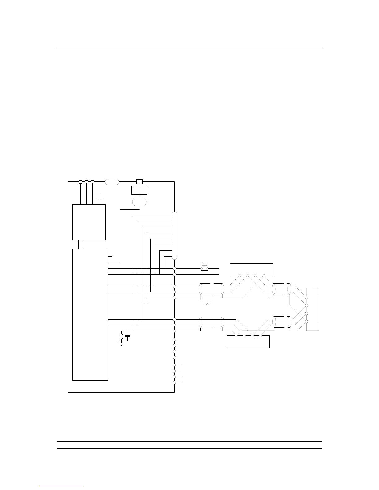
7.3 Field Wiring
The field wiring includes the loop wires to the field units. The loop cable should have an overall
electrical screen. Particular attention should be paid to the connection of the screen on this cable.
The wiring should be in accordance with the diagram Fig. 9. (For connecting up a Hot Standby system
refer to section 10.)
Note that the system is a current loop, and that Port A Out, (terminal 12), connects via all the field
units to Port B In, (terminal 16), whilst Port B Out, (terminal 15), connects similarly to Port A In,
(terminal 13). If a coloured pair, red and blue, is used this results in say the red wires being in
terminals 12 and 16, with the blue wires in 13 and 15. The order is red, blue, blue, red.
Fig 9: Typical System Wiring Diagram
Actuator Terminals
ABC
Scr
A
c
t
u
a
t
o
r
T
e
r
m
i
n
a
l
s
A
B
C
S
c
r
Actuator Terminals
ABCScr
Emergency
Shutdown
17
16
15
14
13
12
11
10
10
11
12
13
14
15
16
17
18
19
20
21
22
23
24
25
Field
Connector
Port A Out
Port A In
Port B Out
Port B In
These links must be fitted
when there is no PS300
Switch Module in the rack
LNE
Mains
Supply
Port 1
RS485
Port 2
RS232
Ethernet
RJ45
Signal Earth Bar
Screen of 2 wire loop connected
directly to earth at one end only
LK1
NB2
Power
Supply
PS210
Processors
and
Display
PS100
Pakscan IIE Master Station
PS602
Page 29
Installation and Connection
29 of 132 Publication S177E V2.0 Issue 12/04
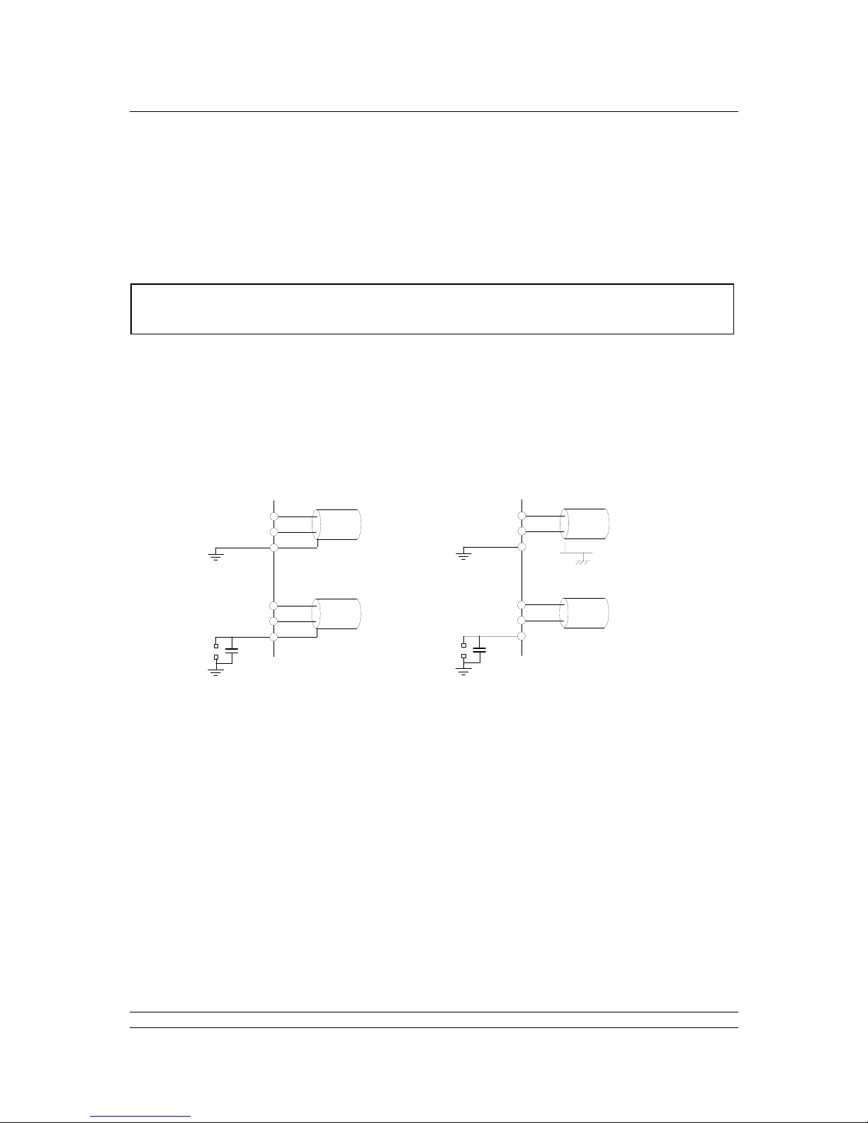
7.3.1 Screen Connections
The screen terminal 14 is connected internally to the supply earth pin, and the chassis. Terminal 17 is
connected to earth via a capacitor, (to meet the CE specification for EMC emission standard), or
directly to earth if link LK1 for master station A or hot standby systems, or LK2 for master station B, is
fitted. If no alternative clean earth bar is provided then the screen will have to connect to the supply or
safety earth.
If you choose to use the internal earth point on terminal 14 or 17 you must ensure that a safety earth is
connected to the master station. Connect the screen of the cable on one side only, say Port A using
terminal 14. DO NOT CONNECT THE SCREEN ON BOTH ENDS OF THE CABLE IF LK1 (LK2 for
station B) IS FITTED. If you connected the loop directly to earth at two or more points, an earth loop
will result that will probably degrade the loop communications.
If your system includes a Signal Earth bar then connect the screen of one of the loop cables to this bar
only. Do not link the bar to the master station earth via the cable screen and terminal 14.
7.4 Loop Checks
Once the loop is fully wired there are a number of checks that should be made before power is applied
to any of the connected field units, actuators, or the master station. These simple tests will always help
in the setting to work of the system.
7.4.1 Loop Continuity.
With all the field units connected, but none of them powered up, check the continuity of the 2 cores of
the cable using a simple resistance (ohm) meter. [The most common errors in installing the system
occur on the field wiring.]
1. Disconnect all the loop wires and the screen from the master station.
12
13
14
15
16
17
Port A Out
Port A In
Port B Out
Port B In
LK1
12
13
14
15
16
17
Port A Out
Port A In
Port B Out
Port B In
LK1
Safety Earth
Safety Earth
Signal Earth
Safety Earth
Safety Earth
Fig 10: Typical Screen Connection
Note: The screen must only be connected directly to earth at one point, and at one end of
the cable.
Page 30

Pakscan IIE System Manual
30 of 132 Publication S177E V2.0 Issue 03/05
2. Measure, and note down, the resistance of each core (the core connected to A and B will
have a higher resistance than the core connected to the common).
3. Check the resistance between the cores, this should be a high resistance as they are not
connected together. (Note that if a field unit has power to it, then the internal circuitry will
connect the two cores together.)
4. Join the 2 wires that will be connected to Port B together and measure the total resistance of
the whole loop cable - note this down as you will need it for reference later.
7.4.2 Screen Continuity
With the Port B cables still connected together make sure that the screen is isolated from the loop
cores themselves, there should be a high resistance between screen and cores.
5. Check the screen is continuous by measuring the resistance of the screen between the two
ends.
6. Check that the screen is isolated from earth by measuring the resistance between the screen
and your screen earth point.
7.4.3 Cable Capacitance
The capacitance between the cores, and to the screen, is critical to the system performance. Too high
a capacitance for the selected loop baud rate will result in poor communications, or even
communication failure.
7. Disconnect the join between the 2 cores that connect to Port B, the cores and screen are now
all separated.
8. With the digital meter set to capacitance, measure the core to core capacitance, and note it
down.
9. Also measure the core to screen capacitance, which will probably be slightly higher, for cable
core 1.
10. Measure the capacitance between core 2 and the screen.
If any problems are encountered during these tests rectify them before proceeding. The results should
be noted on a form such as that shown overleaf.
Page 31

Installation and Connection
31 of 132 Publication S177E V2.0 Issue 12/04
Results of Cable Checks
1 Resistance of Core 1 (A-B)
2 Resistance of Core 2 (Common)
3 Resistance between Core 1 and 2
4 Total Resistance of both Cores [should be the total of (1) and (2)]
5 Screen end to end Resistance
6 Cable to Screen Resistance [should be high]
7 Screen to Earth Resistance [should be high]
8 Capacitance Core to Core
9 Capacitance Core 1 to Screen
10 Capacitance Core 2 to Screen [should be the same as (9)]
Page 32

Pakscan IIE System Manual
32 of 132 Publication S177E V2.0 Issue 03/05
(This page is intentionally blank)
Page 33

Interface and Menus
33 of 132 Publication S177E V2.0 Issue 03/05
8 LOCAL USER INTERFACE
The master station has indication LEDs to show the condition of the hardware and also contains the
main 4 line LCD display and keypad. This section describes the use of this display panel and also the
menu structure for access to the various screens and settings for the system.
8.1 Front Panel Indication LEDs
The Standby Mode LED will only illuminate in a hot standby master station, and then only on the unit
that is currently in standby mode. This can be either the left or right hand PS100 module.
The loop activity indicators flicker as data is transmitted and received, if they both operate together the
loop is complete, but if they alternate then a loop fault exists.
Field Alarm
New
Alarm
Addr
Fault
Host Active
Masterstation
Active
Alarm
PS100
PS100
Standby
Port
A
Port
B
Contrast
Menu
123
654
789
0
*
LOAD
CLEAR
Configuration
Master MSTAG001
Status=LB Off ESD
9>Alms=P
1>M/S 2>Field Units
Field Alarm (yellow)
Illuminates to indicate that a
field alarm is
p
resent
Standby Mode (yellow)
Illuminates when the master
station is forced into standby
by the other master station
of a dual standby pair
Port A (red)
Illuminates to
indicate that current
is flowing into port
A's receiver
Two potentiometers
used during loop
commissioning
Port B (red)
Illuminates to
indicate that current
is flowing into port
B's receiver
LCD Contrast Adjust
Potentiometer
For adjusting the viewing
angle of the LCD screen.
Master Station Alarm (red)
Illuminates when a master
station alarm occurs.
Master Station
Healthy (green)
Illuminates when the
master station
program is running
correctly
Host comms Active
(yellow)
Illuminates to
indicate that data is
on either the RS232
or RS485 highway
Address Fault
(yellow)
Illuminates to
indicate that an
address fault has
occurred.
New Field Alarm (yellow)
Illuminates to indicate that a
new field alarm has
occurred. Cancelled by
accepting an alarm
Fig 11: Master Station Front showing function of LED’s
Page 34

Pakscan IIE System Manual
34 of 132 Publication S177E V2.0 Issue 03/05
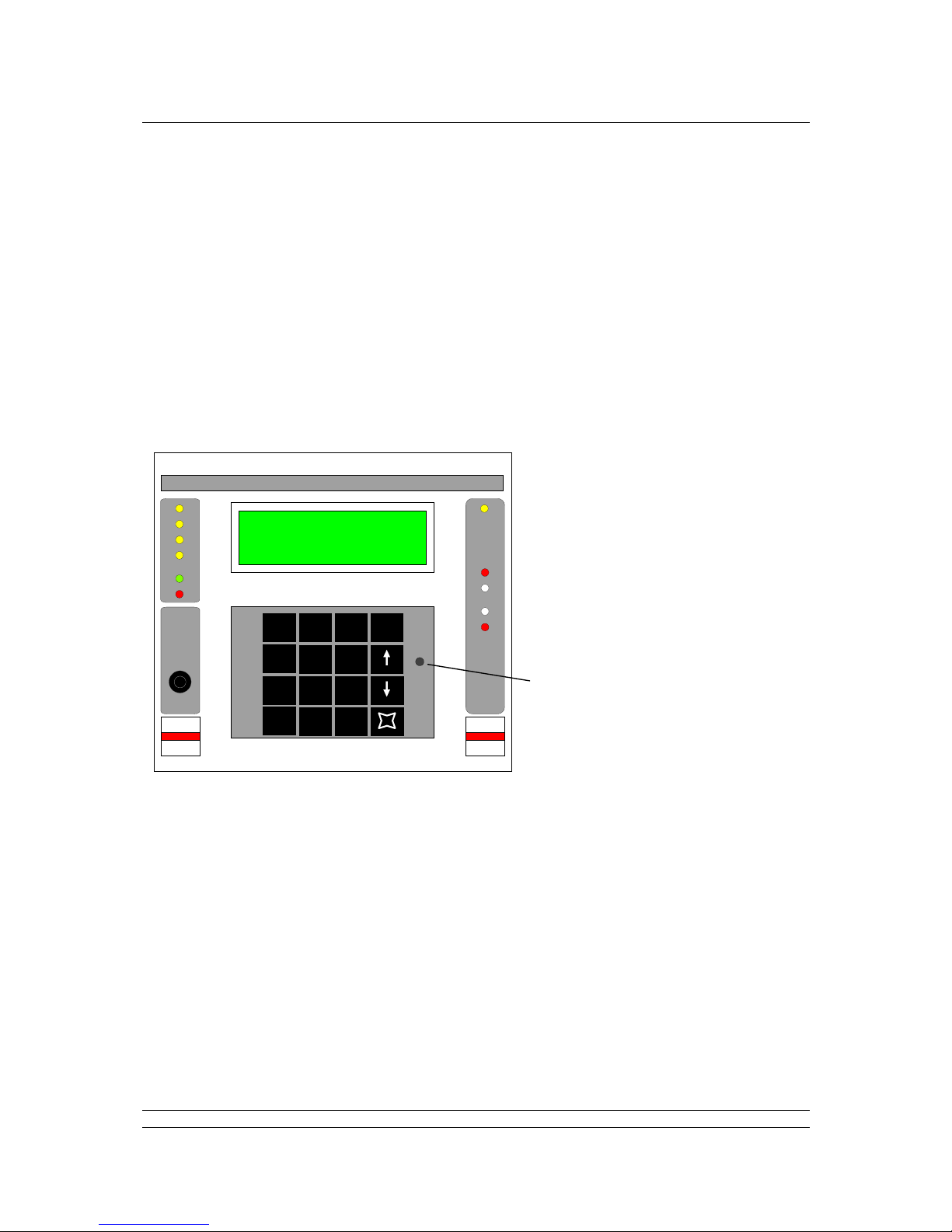
8.2 LCD Screen and Keypad
The screen is used to show the current status of the system and also to allow changes to be made to
the configuration of the system. The keypad is always available to view data although alterations to
settings and commands to valves can be prevented by the use of a PIN entry.
Like all LCD displays, the Pakscan screen has an optimum viewing angle and for best result s the
contrast should be adjusted when the station is finally mounted. On start up when power is first
applied there is a delay before the screen shows the current st atus.
Navigation between the screens always uses numbers and the function of the numbers is displayed
on the bottom line of the LCD. The menu structure used for the master station is shown in the next
section.
All number displays on the LCD are decimal format.
Field Alarm
New
Alarm
Addr
Fault
Host Active
Masterstation
Active
Alarm
PS100
PS100
Standby
Port
A
Port
B
Contrast
Menu
123
654
789
0
*
LOAD
CLEAR
Configuration
Master MSTAG001
Status=LB Off ESD
9>Alms=P
1>M/S 2>Field Units
The LCD screen can display
4 lines of 20 characters and
the
keypad has 16 keys
The CLEAR key clears a
number currently being
entered and accepts alarms
The UP and DOWN keys
(indicated with arrows)
provide an alternative to the
number keys for some
choices. Within the field unit
menus, they allow the user to
move directly from one field
unit to the next
The MENU key (indicated
with a
symbol) returns you
to the previous menu. If
pressed in the middle of
entering a number, that
operation is abandoned
The LOAD key is used to
complete entry of a number
or command
The » key is used to call up
the PIN entry screen from
any screen.
Press
», type the PIN then
press
LOAD
The number keys (0 to 9)
are used for numeric entry
and also to select options
from the menu
Fig 12: Master Station Front showing keypad and LCD screen
Page 35

Interface and Menus
35 of 132 Publication S177E V2.0 Issue 12/04
8.3 Keypad Security
The Pakscan IIE master station can be protected against unauthorised changes by a password, or
'PIN', mechanism.
8.3.1 Using a PIN
The PIN can be entered from any screen by pressing the star key (»). The master station then
prompts for a PIN that should be entered, followed by 'LOAD', before being returned to the previous
screen. The numbers entered are not displayed as they are keyed.
8.4 Menu Structure
Each page offers the user options to enter commands or move to a different page. The structure of
these menus is outlined in the diagram and detailed in the following sections. The menu pages that
appear depend on the connected field units and options chosen.
Menu pages are reached by using the number keys on the control pad. Commands and settings of the
system require that the correct security level is chosen and, when selected, the PIN is entered. All
commands must be verified by the
LOAD key and may be cancelled by the CLEAR key. The MENU
key always returns to a higher level in the structure.
Note: If a PIN has been programmed, it must be entered before particular func tions can be
accessed. These functions then remain accessible whilst keys are being pressed and
for 30 seconds after the last key press.
Note: It is not always possible to recover a ‘lost’ PIN. There is no default PIN. Once lost the
only way to recover the system is to remove the battery which results in total data
loss. In some cases, returning the unit to Rotork may allow a Pin to be recovered.
Top Menu (Master station status)
Field Unit menusMaster station menus
Flowpak
Analogue
GPFCU
ActuatorCommands
Diagnostic
Setup
Fig 13: Master Station Functional Menu Structure
Page 36

Pakscan IIE System Manual
36 of 132 Publication S177E V2.0 Issue 03/05
Top Menu – Master Station Status
1. Master Station Status, Alarms and Tag
1. Reset Loop (reconfigure the 2-wire loop)
2. Start Configuration Mode (enable the use of MasterTools)
3. Change Master (Hot Standby Systems only)
4. Diagnostics (enter Diagnostic mode) Software Version, Port status
1. Port 1 Port Activity
2. Port 2 Port Activity
3. Loop Loop status
1. Loop Map
2. Loop Test
3. Address fault prompt
4. Inter Unit comms
5. Setup (enter Setup mode)
1. Ports
1 or 2 Select Port 1 or 2
1. Set use (Port 2 only)
2. Set protocol
3. Set speed
4. Set Parity
5. Set Port mode when Standby
Passive or Active
6. Set Alarm Options
Separate or Linked alarms for ports
2. Standby Setup Actions
1. Copy data to standby
2. Copy address to standby
3. Copy Master Station Tag to standby
3. Loop Shows current loop status and settings
1. Set speed (shows current speed)
2. Set new FCU speed (for global change)
3. Set Number of FCU
4. Set Doubling status
5. More options
1. Retain last data on comms fail
2. IQ DV convert (0% to ‘Close’)
4. Address Shows current address settings
Set master station address
5. Tags Sets up all tags
1. Set master station tag
2. Select FCU nu mber (to change tag)
3. Set FCU tag
6. Time Shows current date and time setting
1. Set Date
2. Set Time
7. ESD Shows current ESD option settings
1. Enable/Disable Serial Comms ESD
2. Enable/Disable Keypad ESD
3. Enable/Disable hard wired ESD input
8. Security Shows current security level
1. Set PIN in or out of use
2. Set PIN
3. Set access level
9. ESD (initiate an ESD)
Page 37

Interface and Menus
37 of 132 Publication S177E V2.0 Issue 12/04
Top Menu – Master Station Status
2. Field Units Shows status of selected field unit
For non IQ Actuators -
1. Open command
2. Close command
3. Stop command
4. Set Desired Value output
5. Block and Parameter screen
9. Alarms text
1. Next alarm (if there is one)
For General Purpose FCU
1. Show relay output status
1. Control relay 1
2. Control relay 2
3. Control relay 3
4. Control relay 4
5. Set analogue output
6. Block and Parameter screen
9. Alarms text
1. Next alarm (if there is one)
For IQ Analogue field unit
1. Go to Block and Parameter screen
9. Alarms text
1. Next alarm (if there is one)
For IQ Actuators
1. Open command
2. Close command
3. Stop command
4. Set Desired Value output
5. IQ secondary status (Aux Inputs)
1. IQ Opening Torque display
1. IQ Closing Torque display
2. Reload opening torque
3. Block and Parameter screen
2. Block and Parameter screen
9. Alarms text
1. Next alarm (if there is one)
For devices not communicating
5. Block and Parameter screen
1. FCU number
2. Block select
3. Parameter
select
9. Alarm Data (full text alarm message – only visible if an alarm is present)
Page 38

Pakscan IIE System Manual
38 of 132 Publication S177E V2.0 Issue 03/05
8.5 Master Station Status
Master tag
Master MSTAG001
Status
Status=LB OFF ESD
Alarms
9>Alarms=P
Options
1>M/S 2>Field Units
This is the first master station screen that is displayed at power-up
The Master Tag is an identity tag that can be configured by the user.
The Status line indicates the loopback status and the ESD input state. The loopback state is displayed
as:
LB OFF - loopbacks are all off
LB ON - loopbacks are in use, i.e. there is a loop fault
LB busy - this message appears during loop re-configuration and is one of the following;
1. LBbusy: Wait for LB 1 (first wait for loopbacks to come on)
2. LBbusy: Find FCU's on A (finding FCU's on port A)
3. LBbusy: Test Loop (testing for complete loop)
4. LBbusy: Find FCU's on B (finding FCU's on port B)
5. LBbusy: Wait for LB 2 (second wait for loopbacks to come on)
6. LBbusy: LBs off on A (removing loopbacks from port A)
7. LBbusy: LBs off on B (removing loopbacks from port B)
(The normal sequence for a fault free loop would be 1, 2 and 3. A sequence for a break in the loop
anywhere except at port A or port B, would be 1 to 7. Some of the phases may be very quick,
particularly at higher baud rates, and so may not be displayed as the LCD update rate is about twice a
second.)
ESD - master station in ESD mode, e.g. ESD link broken
The Alarms line
shows master station alarms by means of code letters:
F - Memory failure B - Low battery
P - Power on re set A - Field unit address fault
auto LB - Automatic loopback occurred
Commands av ailable:
- Accept alarms
- Go to master station menu
- Go to field unit status page
-
Go to alarm detail page (displays full text of system alarms present)
CLEAR
1
2
9
Page 39

Interface and Menus
39 of 132 Publication S177E V2.0 Issue 12/04
8.5.1 Master Station Commands
1>Reset Loop 9>ESD
2>Start Config Mode
3>Change Master
4>Diagnostic 5>Setup
This screen provides commands and options for the master station itself. The PIN number m ay require
to be entered before some functions are permitted. Config Mode forces the selected serial port to a
fixed setup so that MasterTools utility can communicate via that port. The RS232/RS485 settings must
be made independently. (MasterTools is the Rotork supplied utility used to read and write setup and
tag data with a PC.)
Commands av ailable:
- Command to re-configure loop. This should be used after a loop fault has
been corrected
- Start or stop Configuration Mode. A port selection screen appears to set the
comms port to use with the MasterTools utility.
- (Hot Standby systems only) Relinquish control and allow the other unit to
take over.
- Go to diagnostic menu
-
Go to setup menu
- Send ESD command to all field units. This option is only displayed if the
Keypad ESD has been enabled.
- Return to previous menu
After pressing either of the command keys 1, 3 or 9, a confirmation message screen appears asking
whether you wish to send the command (e.g. after pressing 1, the Reset Loop key, the following will
appear)
Reset Loop Command
LOAD to confirm
CLEAR to cancel
- Confirms the command previously selected and executes it.
- Cancels the command previously selected.
1
2
4
5
9
MENU
LOAD
CLEAR
3
Page 40

Pakscan IIE System Manual
40 of 132 Publication S177E V2.0 Issue 03/05
8.5.2 Master Station Alarms - Text Description
Number of system alarms
1 System Alarms
Alarm description
Power up Reset
View the next alarm
1>Next Alarm
This page gives an English text description of the master station alarms that appear as single letters
on the Master Station Status screen.
The first line shows how many unacknowledged or current master station alarms there are.
The third line gives a full text description of each alarm in turn.
Pressing “1” displays the text string for the next alarm. Pressing “1” on the last alarm, brings up the
first alarm.
The following table shows the text displayed for each of the letter codes,
Letter Alarm Text
F
Memory failure
A
Address fault
P
Power up reset
W
Watchdog reset
B
Battery low
Auto LB
Auto loopback
Commands av ailable:
- View next alarm text description
- Return to previous menu
- Cancels the command previously selected.
1
MENU
CLEAR
Page 41

Interface and Menus
41 of 132 Publication S177E V2.0 Issue 12/04
8.6 Configuration Mode Screen
Select Port for
Upload and Download:
1>Port 1
2>Port 2
This mode forces the selected port to adopt speed, protocol and address parameters that match the
settings needed for the MasterTools utility. MasterTools runs on a PC and allows the master station
settings to be modified using a PC screen and keyboard. In addition MasterTools will record all the
settings present and those of the attached field units. Tags for all devices can be set with the utility.
Select the port to use bearing in mind that the PC probably requires RS232 communications. The
hardware connection to the master station must still match the PC. This means that for direct
communication Port 2 (the RS232 port) should be used.
Commands available:
- Selects Port 1
- Selects Port 2
- Return to previous menu
Once selected the screen changes to that below (shown with Port 2 selected) and the port adopts the
settings shown irrespective of the configured settings.
Select Port for
Upload and Download:
Port 2 Config Mode
9600, odd Par, Addr1
When Configuration Mode has been finished with select Menu to return to the main menu. The master
station will reload the original or newly set configured values for the port’s settings.
Commands available:
- Return to previous menu
1
2
MENU
MENU
Page 42

Pakscan IIE System Manual
42 of 132 Publication S177E V2.0 Issue 03/05
8.7 Diagnostic Menus
8.7.1 Top Diagnostic Display
Software version
S/W:0124 V5. 8/V5. 2
Port 1 activity
1>Port 1 Rx Tx
Port 2 activity
2>Port 2 Rx Tx
Loop diagnostics
3>Loop 1 x2 >4
Inter-unit comms
The top line shows the code for the software type fitted and its version numbers:
011X
- single master station
012X
- hot standby master station
01X1 - 60 channel unit
01X2 - 120 channel unit
01X3 - 180 channel unit
01X4 - 240 channel unit
(X
means doesn’t matter)
V5.8/V5.2 - V25 card software version, (5206-014) and loop driver software version,
(5206-034)
The port activity
flags flash to indicate when a message is received (Rx), or when a reply is transmitted
(Tx).
The centre of the fourth line contains a number that indicates loop activity and the field unit that is
currently passing data to the master station (0 or 255 may be shown when no data is being passed),
The message ‘x2’ indicates when the loop is running at double speed. Inter-unit communications
applies to hot standby systems only and is information about the data exchange between the two units
in the hot standby pair.
Commands available:
- Go to Port 1 diagnostic page
- Go to Port 2 diagnostic page
- Go to Loop diagnostic page
- Go to Inter-unit comms page (hot standby systems only)
- Return to previous menu
1
2
3
MENU
4
Page 43

Interface and Menus
43 of 132 Publication S177E V2.0 Issue 12/04
8.7.2 Modbus Port Diagnostic Displays
Port number
1 msg err xcpt crc
Message counts
123 0 0 0
Mod func addr data
Last message details
1 2 1920 48
The illustration shows the diagnostic display for Port 1, the display for Port 2 is similar.
These screens give detailed diagnostic information for the serial links; the Port number is shown on
the top line. The top half displays numerical count for various message types since the last time the
display was reset (cleared to 0):
msg - number of valid messages received
err - number of errors, e.g. overrun errors, parity errors, Baud rate errors
xcpt - number of Modbus exception responses generated
crc - number of messages received with incorrect CRC's
The bottom half shows details of the last message received, (the address and data in decimal format):
Mod - the Modbus address of the last request
func - the Modbus function code of the last request
addr - the discrete bit or register number in the last request
data - the data field of the last request, typically the number of points or registers
Some familiarity with the protocol is needed to make use of this display. Its purpose is help in
commissioning a serial communications link to a Host computer by making the master station show
the received data as it interpreted it. By referring to the protocol specification the validity of the
messages can be checked. The display is normally 'frozen' and is only updated when a key is pressed
(any key except the Menu key). This gives time to take note of the numbers. Most Host systems are
set up to send out a short sequence of requests for data, and by pressing a key a few times it is
possible to capture all the messages. The "Clear" key resets the counters on the top half of the
screen.
Commands available:
- Zeros the message and error counts
- Or any other key except Clear or Menu updates display with the last
message
- Return to previous menu
MENU
LOAD
CLEAR
Page 44

Pakscan IIE System Manual
44 of 132 Publication S177E V2.0 Issue 03/05
8.7.3 Printer port diagnostic display
Port number
1 len pin pout err
Print queue
1 0 0 0
The master station port 2 supports a serial (RS232) printer or similar generic device. If Port 2 is set for
Printer use then the diagnostic display will be changed from that shown in section 8.7.2 Modbus Port
Diagnostic Displays to the one shown above.
The screen shows the following data:
len - number messages queued up to be printed
pin - printer queue input pointer
pout - printer queue output pointer
err - number of overflow errors, (indicated the master station buffer is full)
Commands available:
- Return to previous menu
MENU
Page 45

Interface and Menus
45 of 132 Publication S177E V2.0 Issue 12/04
8.7.4 Loop Diagnostic Display
Reason for loop configuration
Loop: Fault Found
Fault Found
Loop open circuit
Address of fault details
Loopbacks at 4 5
FCU map/Test/Address fault
1>Map 2>Test 3>Addr
This screen provides information to aid in commissioning and fault finding on the current loop.
Additional screens below this one also contain useful data on the loop status and connected field
units.
The first line gives the Reason message and shows the reason why the loop was last re-configured.
The message will be one of the following:
Power on Reset - loop configured because the master station powered up
Fault Found - fault detected on the loop whilst it was running without loopbacks
present
Fault Found A - fault detected on the A side of broken loop whilst running with
loopbacks on
Fault Found B - fault detected on the B side of broken loop whilst running with
loopbacks on
Reset Command - loop Reconfigure command entered from keypad or serial port
Return wire fault - fault detected in the return current path whilst the loop was running
at double speed
Doubling failed - fault detected after loop assumed double speed.
If a fault occurs, the Fault Found message will be one of the following:
Zero Address - a field unit has been found with an address of zero
Address too High xx - a field unit has been found with an address higher than that setup
within the master station, xx is the address
Same Address xx - two field units found with the same address, xx is the address
Loop Open Circuit - an open circuit fault found on the loop
Loop Short Circuit - a short circuit fault found on the loop
If a fault occurs the message on the third line will be:
Position xx - xx is the position from A of zero address or address too high
Positions xx yy - xx and yy are the positions from A of the duplicate addresses
Loopbacks at xx yy - cable fault lies between xx and yy
If there are no loop faults then lines 2 and 3 will be blank. If there is more than one loop fault the
display shows the first one detected.
Note: In the case of address faults, the master station will continue to operate the loop,
missing out the faulty field units. The fault details can be found with command 3.
Page 46

Pakscan IIE System Manual
46 of 132 Publication S177E V2.0 Issue 03/05
Commands available:
- Go to FCU map screen
- Loop speed test (only possible if loop is complete)
- Field Unit address fault details (only available if an address fault is present)
- Return to previous menu
1
2
3
MENU
Page 47

Interface and Menus
47 of 132 Publication S177E V2.0 Issue 12/04
8.7.4.1 FCU Map and Failure Counts
Physical position
Loop Position = 72
Address
FCU Address = 17
Attached port
Port=A Fails = 5
Comms fail count
Field unit type
Type=Act S/W = 2.07
Software version
The screen displays information about field units found on the loop during loop configuration.
The top line shows the physical position on the loop, the second line the address of the field unit found
at that position, and the third line the master station port it is attached to. For a complete loop with no
loopbacks, all the field units are attached to port A.
The third line also shows a count of communication errors with the field unit whose address is
displayed above. The count has a range of 0 to 255, after which it rolls around to zero. The counter
increments for every communication error though the system will only announce a ‘Comms failure’
when 3 successive tries have failed to locate the field unit. This counter therefore reflects the
communications condition and can be used as an indicator of the health of the field unit to asses the
probability of failure in the future.
The bottom line shows the type of field unit and the software version of the EPROM. "Type" can be
displayed as:
Act - Non - IQ Actuator
IQ - IQ or IQT Actuator
GP - General Purpose Field Unit
IQA - IQ or IQT Analogue
PPk - Flowpak actuator
Information for this screen is available approximately 30 seconds after loop configuration is complete
and is updated approximately once a minute after that.
The example screen above shows that at loop position 72 there is field unit address 17, and it is
attached to port A, that it is an actuator field unit with software version 2.07 and that 5 communications
failures have been recorded for it since the system was last reset.
Commands available:
- Move to the next field unit
- Move back to previous field unit
- Return to previous menu
MENU
Page 48

Pakscan IIE System Manual
48 of 132 Publication S177E V2.0 Issue 03/05
8.7.4.2 Loop Speed Test
Loop Speed Test
Speed selection
1>Loop Speed = 1200
Perform test
2>Test
Test result
Result 100%
This screen allows the user to cause test messages to be sent around the loop at a defined baud rate.
After each test the loop returns to normal speed so that the interruption to FCU communications is
minimal. (The loop speed test should be done at speeds higher than the loop is currently running at).
The result of the test is displayed as a percentage success rate so that the user may have a degree of
confidence in the performance with the loop speed chosen.
Commands available
- Select the test speed, pressing ‘1’ will scroll through the speed options
- Perform test. This causes a test message to be sent around the loop 10
times
- Return to previous menu
The loop speed options are 300, 450, 600, 900, 1200, 1800, 2400, 3600, 4800, and 7200. Some of
these speeds cannot be selected for normal use, however they do provide information about the
performance margin available.
1
2
MENU
Page 49

Interface and Menus
49 of 132 Publication S177E V2.0 Issue 12/04
8.7.4.3 FCU Address Fault Details
FCU Address Fault
Duplicate Address
Address 10
15 on A & 139 on B
This screen shows details of any address fault present on the loop.
Line 2 shows the type of fault. Possible messages are
Duplicate address - More than one field unit with the same address
Address too High - A field unit has an address higher than the set address to scan up to
Zero Address - A field unit has address zero (not permitted)
Line 3 shows the offending address.
Line 4 shows the position of the offending address or addresses. The above example indicates that a
field unit at address 10 was found at position 15 out of port A and at position 139 out of port B. The
display can show only two positions. If the same address occurs 3 or more times on the loop only the
first two will be shown.
If there is more than one address fault on the loop this display will show the last one found.
The FCU map will always show the complete picture, i.e. every FCU found during loop configuration,
including duplicates, however many FCU there are.
Commands available:
- Return to previous menu
MENU
Page 50

Pakscan IIE System Manual
50 of 132 Publication S177E V2.0 Issue 03/05
8.7.5 Hot Standby Inter Unit Diagnostic Display
Inter-Unit Comms
Clock OK Data OK
Watchdog Lo
T 0 C 0 R 1 L 0
This screen gives information about the communications between the two units that make up a hot
standby pair. It is intended mainly as an aid to testing and fault diagnosis.
The signals Clock, Data and Watchdog are interconnected between the two units with each side
having its own set. In normal operation the screens on the two units differ and will show:
Signal Main Unit Standby Unit
Clock OK OK
Data Hi or Lo OK
Watchdog Hi or Lo OK
The signals may transiently change to other values. In addition they will show as below if there is a
fault on the unit.
Signal status Condition
OK The sig nal is good
Hi The signal is stuck at logic ‘1’
Lo The signal is stuck at logic ‘0’
Err The signal is faulty
The last line shows the cumulative counts for 4 important errors. The value can be reset to 0 with the
Clear key. The counters record the data on the side viewed. The sending (Main) side resends
messages if it does not receive a response within the Timeout period. After 2 retries (3 attempts) it
gives up and increments the Limit counter. On system operating normally the counter incremental rate
should be small.
T - Number of Timeouts
C - Number of Checksum errors
R - Number of Retries
L - Number of times retry Limit reached
Commands available:
- Zeros the error counts
- Return to previous menu
MENU
CLEAR
Page 51

Interface and Menus
51 of 132 Publication S177E V2.0 Issue 12/04
8.8 Setup Menus
8.8.1 Top Setup Menu
Port setup
1>Ports 2>Standby
Only shows on hot standby units
Loop options
3>Loop 4>Address
Unit addresses
Set tag names
5>Tags 6>Time
Date and time
ESD options
7>ESD 8>Security
Access level settings
Commands available:
- Go to Port 1 setup page
- Go to Standby mode menu page
- Go to Loop options page
- Change unit address used in communications with host computers,
- Go to FCU Tag names page
- Go to Date and Time setup page
- Go to ESD configuration page
- Go to Access level and security page
- Return to previous menu
Note: The Setup options can be PIN protected. See sections 8.3 and 8.8.9
1
3
4
MENU
5
6
7
8
2
Note: When the Ethernet connections are being used the port settings are critical. See
section 12.
Page 52

Pakscan IIE System Manual
52 of 132 Publication S177E V2.0 Issue 03/05
8.8.2 Port Setup Menus
1>Port 1
2>Port 2
The first screen allows the port to be set up to be selected, press 1 or 2 for port 1 or 2. Press Menu to
return to the previous menu. Once selected a screen similar to the following is revealed.
Port use
1>P1 Use =Host
Protocol
2>Generic Modbus
Baud rate
3>19200 4>Par=Odd
Parity
Comms mode when standby
5>Standby Passive 6>
More options
For Port 1 (always RS485) the ‘Use’ option is restricted to host communication only, whilst Port 2
(always RS232) can be used either for host communication or to operate a serial printer.
Standby Passive or Active
Option 5 is only available on hot standby systems. It is used to set the mode of operation for the port
when the master station (side A and B) is in standby mode. This is usually set to Standby Passive
preventing the port from generating replies to data requests. If it is set to Standby Active then, when
this module (side A or B) is the standby unit the port will remain active and generate responses. The
appropriate setting of this option depends on how the serial communications to the host are organised.
Note that the ports on a master station in Main mode (side A or B) are always active.
Commands available:
- Step around available options, fixed as Host for Port 1, selectable Host or
Printer for Port 2
- Step round the available host communication protocol databases (always
Modbus RTU half duplex, asynchronous communications)
- Step round the baud rate options for the port. Choices are 19200, 9600,
4800 and 2400
- Step round parity options. These are Odd, Even, None or '0' (always set to
zero). Both ports have 1 stop bit and 8 bits/character
- Toggle between Passive (normal) and Active (hot standby systems only)
- Go to alarm linkage screen
- Return to previous menu
MENU
1
2
3
4
6
5
Page 53

Interface and Menus
53 of 132 Publication S177E V2.0 Issue 12/04
8.8.2.1 Alarm Linkage
Port Alarms
1>Separate
This screen allows port alarm handling to be configured. Alarms can either operate completely
independently (‘separate’) for each port, or can be linked such that the same alarm information is
always reported regardless of which serial port is used.
Alarms must be read and accepted before they can clear and return to normal. If configured as
separate, alarm reading and acceptance must be done separately for each of the two ports. This
ensures that the different hosts see all the alarms. When the alarms are linked, accepting an alarm on
one port accepts the alarm on all the other ports as well.
The status screen displays for alarm indication cannot be linked to the serial communications alarm
handling.
Linking the port alarm operations is useful in dual redundant serial link configurations between the
master station and the host computer. When Ethernet communication is being used on hot standby
systems the normal setting should be ‘Linked’.
Commands available:
- Toggle between “Linked” and “Separate”.
- Return to previous menu
1
MENU
Note: Linking links both host serial port alarm handling together. The default option is
Se
p
arate
Page 54

Pakscan IIE System Manual
54 of 132 Publication S177E V2.0 Issue 03/05
8.8.3 Data transfer to Standby Unit
1>Copy to Standby
Copy data to standby unit
ON
2>Copy address ON
Copy master station address
3>Copy M/S tag ON
Copy master station tag
This page displays the “copy to standby” options and their current settings. This option is only
available on hot standby master stations and allows data to be automatically transferred from the main
unit to the standby unit. The default setting for all three options is “ON”.
Commands available:
- Copy all settings from the main to standby unit except those listed below
- Copy the master station Modbus address from main to standby unit.
- Copy the master station tag from main to standby unit.
- Return to previous menu
MENU
1
2
3
Page 55

Interface and Menus
55 of 132 Publication S177E V2.0 Issue 12/04
Note: The loop scan time is minimised by setting the highest number to scan up to (the
highest address). All the addresses in the selected range should be used and gaps in
the address ran
g
e should be avoided. Gaps or unused addresses cause the system to
run more slowly as the unused addresses are still checked. In addition unused
addresses will generate a communication failure alarm.
8.8.4 Loop Setup Menu
1>Speed (now) = 1200
Current speed
2>Speed (new) = 600
Desired speed
3>Number FCUs = 69
Highest address
Doubling enable
4>Doubling – OFF 5>
More options
This page displays and controls the options affecting the current loop.
The master station can program the speed used on the loop. Select the desired speed and it will be
reprogrammed into the field units immediately the loop is next reconfigured.
The 'Doubling Enable' allows loop speed doubling to be enabled (ON) or disabled (OFF). If enabled,
the master station automatically doubles the loop baud rate provided that it finds the loop is complete.
This improves the scan time. In a few cases it may be necessary to disable this feature if it causes a
high error rate on the loop.
Commands available:
- Step round the loop baud rate options. Choices are 110, 300, 600, 1200,
and 2400.
- Step round the desired loop baud rate options. It is possible to select rates in
the range one step up or one step down from the current speed.
- Change the highest field unit address on the loop. The master station polls
all field units up to this highest address. The scan time is minimised if polling
is restricted to only those field units that may be present.
- Toggle between doubling enabled and disabled.
- Further options
- Return to previous menu
MENU
1
2
3
4
5
Page 56

Pakscan IIE System Manual
56 of 132 Publication S177E V2.0 Issue 03/05
8.8.4.1 Further Loop Options
1>Retain data on
Comms fail =OFF
2>IQ DV Convert=OFF
Two further settings for the data on the loop can be made from this screen.
There is an option to make the data held in the Modbus database for each FCU retain the last value
obtained prior to loss of communication with the field unit should this occur. Retaining the data (ON)
has the effect of reporting the last known position of the valve. The alternate option (OFF) is that once
communications is lost the data is cleared to all zeros. Clearing the data ensures that information
cannot falsely report actuator position data. The default value is OFF.
The IQ DV Convert option can be used to ensure that 100% and 0% Desired Value outputs to the IQ
actuators only is transformed into actions to make the actuator run to the fully open (100%) and fully
closed (0%) positions. With IQ DV Convert set to ON, the command message is converted from a DV
command to an Open or Close command. This is useful for positioning actuators where it is possible
that the valve will not fully shut or open when moved by only a small amount. When used for tight shut
off valves with analogue position control only the setting should be ON.
With IQ DV Convert set to OFF the DV command is not changed and the actuator positions to as near
to 0 and 100% as the deadband setting allows. If Limited Range Positioning is being used the setting
must be OFF. The default is OFF.
Commands av ailable:
- Toggle Retain Last Data setting
- Toggle IQ DV Convert option
- Return to previous menu
MENU
1
2
Page 57

Interface and Menus
57 of 132 Publication S177E V2.0 Issue 12/04
8.8.5 Unit Address Setup Menu
1>Masterstation
Modbus slave address
= 1
The master station responds to messages directed at the Modbus slave address set using this page.
Note that in some cases when using Pakscan Generic Modbus protocol settings the master station will
respond to more than one address, and the setting here is the Base address. There is more
information on the base address and offset addresses in the Pakscan Modbus Protocol document
(S171E). Valid Modbus addresses are from 1 to 247 inclusive.
Commands available:
- Set up the Pakscan data Modbus address
- Return to previous menu
MENU
1
Page 58

Pakscan IIE System Manual
58 of 132 Publication S177E V2.0 Issue 03/05
8.8.6 Tag Setup Menu
Master station tag
1>M/S Tag MSTAG001
FCU address
2>FCU = 2
FCU’s tag
3> Tag FCUTAG02
This is the page for editing tag names that may be assigned to the master station and the field units.
Commands available:
- Edit master station's tag
- Change field unit address
- Edit field unit tag
- Go on to next FCU
- Go back to previous FCU
- Return to previous menu
Editing a tag:
An arrow appears beneath the character being edited
MSTAG001
^
Commands av ailable:
- The Up and Down arrow keys are used to scroll through the ch aracters
which can be used in tag names. These are:
'A' to 'Z', '0' to '9', plus '-', and 'Space'. (Numbers 0 to 9 can however, be
entered directly via the keypad)
- Abandon editing and start again
- Accept current character and move onto the next one
- Finish editing
MENU
1
2
3
MENU
LOAD
CLEAR
Page 59

Interface and Menus
59 of 132 Publication S177E V2.0 Issue 12/04
8.8.7 Date and Time Setup
Date
1>Date 25/10/ 5
Time
2>Time 19:32:00
This page shows the state of the internal real-time clock. It is used to tag printer alarm messages with
the time at which the alarm occurred and email messages from the Pakscan Ethernet alarm function
when they are sent.
The date is displayed in the form Day/Month/Year.
The time is displayed in the form Hours:Minutes:Seconds using a 24 hour clock.
Commands available:
- Set date
- Set time
- Return to previous menu
Setting the date:
On pressing '1', the 'Day' field is cleared and you can type in a new day. Correct a mistake by
pressing the 'CLEAR' key. Finish entering the new day by pressing 'LOAD'. The 'Month' field will
then be cleared, and so on.
Setting the time:
This is similar to setting the date.
MENU
1
2
Page 60

Pakscan IIE System Manual
60 of 132 Publication S177E V2.0 Issue 03/05
8.8.8 ESD Options Setup Menu
ESD Options
1>Serial Disabled
2>Keypad Disabled
3>Input Disabled
This page allows the user to select the ESD (emergency shutdown) function. ESD operation can be
enabled or disabled separately for the serial ports, the keypad, and the hardware input. The default
setting for all three controls is all inputs disabled.
Commands available:
- Enables / disables host port ESD input
- Enables / disables keypad ESD input
- Enables / disables hard wired ESD input, (terminals 32 and 33)
- Return to previous menu
MENU
1
2
3
Note: A hard wired input ESD will cause a shutdown action when the contact input is open
circuit. The individual actuator function on receipt of the ESD command is set within
the actuator itself. Valves may close, open or stay put during an ESD event.
Once an ESD command has been issued to the actuator field units, local control is
not available until a new command is sent from the master station to each actuator.
The new command may be open, close or stop.
Page 61

Interface and Menus
61 of 132 Publication S177E V2.0 Issue 12/04
8.8.9 Keypad Security Options
Keypad Security
1>PIN In Use
2>PIN = ****
3>Access Level 3
A security code, PIN, can be set up to prevent unauthorised changes to the master station settings or
field unit outputs. Line two shows ‘
PIN Not In Use’ if no PIN has been set up and ‘PIN In Use’ once a
PIN has been set.
The ‘Access Level’ number on line 3 indicates the operations that are protected by the PIN. The
meaning of these numbers is:
Access level:
1 - No protection. Setup can be changed and keypad commands entered without the PIN.
2 - Setup protection. Setup changes require the PIN but keypad commands do not.
3 - Setup and Command protection. Both setup changes and keypad command s require the PIN.
4 - No keypad commands permitted whilst any host serial communication line is active. [If all
serial communication links are inactive for 5 seconds then keypad commands can be entered
provided the PIN is entered (as with level 3).]
Commands available:
(All changes require either the Access level to be set to 1 or the current PIN to be entered)
- Change the requirement for inputting a PIN. When setting the PIN as ‘Out of
use’ the previously programmed PIN is lost
- Enter a new PIN (when entered it will automatically place PIN ‘In use’). Key
in the PIN required. Numbers between 1000 and 9999 are acceptable.
Mistakes can be corrected using the CLEAR key. Finish entering the PIN by
pressing LOAD. (The shipping default is 1000).
- Change the access level
- Return to previous menu
Entering a PIN from any screen:
- Pressing the
* key reveals the PIN entry screen.
Type in the PIN and then press the LOAD key. If the PIN is correct then
press the MENU key to return to the previous page.
When an action requires the PIN to be entered a screen message ‘PIN required’ is displayed.
MENU
1
2
3
*
Page 62

Pakscan IIE System Manual
62 of 132 Publication S177E V2.0 Issue 03/05
The Up and Down arrow
keys are used to scroll
through the field units
CLEAR - Accept alarms
8.9 Field Unit Menus
The master station displays a screen appropriate to the type of field unit.
8.9.1 Actuator Field Unit Status Display
Digital status
OA1 ST0 MO0 FCUTAG01
Tag name
Digital status
CA0 MR0 MC0 1
FCU address
Measured value (position)
MV=100% 9>Alms=P
Alarm status
FCU commands
1>O 2>C 3>S 4>DV 5>
More options
Digital Status key :
(The display shows a ‘0’ if the state is false and a ‘1’ if it is true)
OA - Open Limit Switch CA - Close Limit Switch
MO - Run ning Open MC - Running Closed
MR - Motor Running ST - Stopped in mid-travel
LB - appears if field unit is in loopback
Alarms key:
(The letter is present if the alarm has occurred)
F - FCU memory failure j - Valve jammed
P - Power on reset o - Valve obstructed
C - Communications failure e - Motor running at end of travel
W - Watchdog reset m - Manual operation
r - Monitor relay s - Start/Stop failure
l - Local stop pressed a - Auxiliary override alarm (IQ only)
c - Control Not Available x - Travel time exceeded (IQ only)
t - Thermostat tripped
Commands av ailable:
- Send Open command
- Send Close command
- Send Stop command
- Send Set DV command. The master station prompts for the new DV before
sending the command
- Go to secondary data page
- Go to alarm detail page (full text details of field unit alarms)
- Return to previous menu
MENU
1
2
3
4
5
Note: When the Access Level is set to 3 or 4, to issue a command the correct PIN must be
entered first. Pressing command keys 1, 2, 3, or 4 causes a confirmation screen to
appear before the command is sent.
CLEAR
9
Page 63

Interface and Menus
63 of 132 Publication S177E V2.0 Issue 12/04
8.9.1.1 IQ Actuator Second Status Page
Current torque
Torq=85% FCUTAG01
Tag name
Auxiliary inputs
Aux1=1 Aux2=0 1
FCU address
Aux3=0 Aux4=0 LoBat
Battery status
1>Torque 2>
More options
This screen only appears for IQ and similar actuators, it shows the current torque value and the statu s
of the 4 auxiliary digital inputs on an IQ actuator. The flag "LoBat" is displayed if the field unit is
reporting that the battery within the actuator is low.
Commands available:
- Go to next field unit
- Go to previous field unit
- Go to torque display screen
- Go to secondary data page
- Return to previous menu
MENU
1
2
Page 64

Pakscan IIE System Manual
64 of 132 Publication S177E V2.0 Issue 03/05
8.9.1.2 IQ and IQT Historic Torque Displays
Open Torq FCUTAG01
Close Torq FCUTAG01
101 83 74 62 1
96 85 70 58 1
59 67 81 98<Open
57 65 78 92<Open
1>Close 2>Reload 3>
1>Open 2>Reload 3>
These screens show 8 values of torque for the actuator travelling in the opening or closing direction.
They are the values that have been most recently received from the field unit. The 8 values refer to the
actuator motor torque at the following positions of the actuators stroke, 6%, 19%, 31%, 44%, 56%,
69%, 81% and 94%. Thus on the "Open Torque" example screen shown above, 101% is the torque
value at 6% open, 83% is the torque value at 19% open, etc.
Torque values are displayed as percent of rated torque and have a range of 0 to 120%.
If the IQ field unit has been programmed with a torque filter factor of “000” then these 8 torque values
are automatically returned to the master station once the actuator has travelled from one end of travel
to the other. However, if the filter factor has been set to a value greater than “000” these values are
only returned when the reload button (2) is pressed. Pressing reload will also cause the master station
to fetch the torque values when the actuator has not travelled from end to end, irrespective of filter
factor setting. If the actuator is not an IQ, but uses an IQ actuator field unit these pages will appear,
but will not be populated with data.
Commands available:
- Go to next field unit
- Go to previous field unit
- Toggle between opening and closing torque screens
- Reload new torque values
- Go to secondary data page
- Return to previous menu
MENU
1
2
3
Note: If the actuator has been moved over part of its stroke, e.g. from 20% to 60% open,
then the torque values outside that range may have been reset to zero.
Page 65

Interface and Menus
65 of 132 Publication S177E V2.0 Issue 12/04
The Up and Down arrow
keys are used to scroll
through the field units
CLEAR - Accept alarms
8.9.2 Flowpak Actuator Field Unit Status Display
Digital status
OS1 ST0 TO0 FCUTAG01
Tag name
Digital status
CS0 TR0 TC0 1
FCU address
Measured value (position)
MV=100% 9>Alms=P
Alarm status
FCU commands
1>O 2>C 3>S 4>DV 5>
More options
Digital Status key :
(The display shows a ‘0’ if the state is false and a ‘1’ if it is true)
OS - Open Limit Switch ST - Stopped in mid-travel
TO - Travelling Open CS - Close Limit Switch
TR - Valve Travelling TC - Travelling Closed
LB - appears if field unit is in loopback
Alarms key:
(The letter is present if the alarm has occurred)
F - FCU memory failure j - Valve jammed
P - Power on reset o - Valve obstructed
C - Communications failure l - Local stop pressed
W - Watchdog reset r - Monitor relay
s - Start/Stop failure t - Low pressure
m - Manual operation c - Control Not Available
Commands av ailable:
- Send Open command
- Send Close command
- Send Stop command
- Send Set DV command.
The master station prompts for the new DV before sending the command
- Go to secondary data page
- Go to alarm detail page (full text details of field unit alarms)
- Return to previous menu
MENU
1
2
3
4
5
Note: When the Access Level is set to 3 or 4, to issue a command the correct PIN must be
entered first. Pressing command keys 1, 2, 3, or 4 causes a confirmation screen to
appear before the command is sent.
CLEAR
9
Page 66

Pakscan IIE System Manual
66 of 132 Publication S177E V2.0 Issue 03/05
The Up and Down arrow
keys are used to scroll
through the field units
CLEAR - Accept alarms
8.9.3 General Purpose Field Unit Status Display
DIN1->DIN8 FCUTAG01
Tag name
Digital inputs
00001111 1
FCU address
Measured value 1
A1= 75% 9>Alms=P
Alarms
Measured value 2
A2= 50% 1>More
Commands page
The status of the eight digital inputs is displayed as eight 0's or 1's. A 1 indicates that the input is true.
The alarms code letters are the same as for an actuator field unit. However, only memory failure (F),
comms failure (C), power on reset (P) and watchdog timer (W) are valid alarms. As with the actuator
page there is a full text display of the alarms that may be found by pressing 9.
Alarms key:
(The letter is present if the alarm has occurred)
F - FCU memory failure
P - Power on reset
C - Communications failure
W - Watchdog reset
The commands are accessed by going to a second page (press 1). This is because there is more d ata
than for an actuator field unit.
Commands av ailable:
- Go to commands page
- Go to alarm detail page (full text details of field unit alarms)
- Return to previous menu
MENU
9
1
CLEAR
Page 67

Interface and Menus
67 of 132 Publication S177E V2.0 Issue 12/04
8.9.3.1 Second Page for General Purpose Field Unit
Pulse counter
Pulses= 44 FCUTAG01
Tag name
Relay commands
1>R1=0 2>R2=0 1
FCU address
3>R3=0 4>R4=0
Analogue output
5>Aout= 0% 6>
Block and parameter screen
Digital input 1 on a GPFCU can be used as a pulse counter. The master station screen will count
pulses up to 9999 before rolling over to 0 and starting again.
Options 1 to 4 prompt the user to Energise (1) or De-energise (0) the relay before the command is
sent.
Option 5 prompts the user to enter a data value for the analogue output in the range 0 to 100 %.
Commands available:
- Go to next field unit
- Go to previous field unit
- Operate relay 1
- Operate relay 2
- Operate relay 3
- Operate relay 4
- Set analogue output
- Go to secondary data page
- Return to previous menu
MENU
1
2
3
4
5
6
Note: The general Purpose Field Unit may be configured for fleeting relay outputs, in which
case it will not action the de-ener
g
ise commands, and if the relays are energised their
status will always display 0.
Note: When the Access Level is set to 3 or 4, to issue a command the correct PIN must be
entered first. Pressing command keys 1, 2, 3, or 4 causes a confirmation screen to
appear before the command is sent.
Page 68

Pakscan IIE System Manual
68 of 132 Publication S177E V2.0 Issue 03/05
The Up and Down arrow
keys are used to scroll
through the field units
CLEAR - Accept alarms
8.9.4 IQ Analogue Input Field Unit
Analogue input channel 1
A1= 12% FCUTAG01
Tag name
Analogue input channel 2
A2= 34% 1
FCU address
9>Alms=P
Alarms
5>
Block and parameter screen
The IQ actuator can contain two field units, each with their own loop address. The IQ Analogue Input
field unit collects two analogue signals for display and reporting.
The alarms code letters are the same as for an actuator field unit. However, only memory failure (F),
comms failure (C), power on reset (P) and watchdog timer (W) are valid alarms. As with the actuator
page there is a full text display of the alarms that may be found by pressing 9.
Alarms key:
(The letter is present if the alarm has occurred)
F - FCU memory failure
P - Power on reset
C - Communications failure
W - Watchdog reset
There are no commands associated with this page, though the block and param eter screen does allow
access to the parameters associated with reporting.
Commands available:
- Go to secondary data page
- Go to alarm detail page (full text details of field unit alarms)
- Return to previous menu
MENU
5
CLEAR
9
Page 69

Interface and Menus
69 of 132 Publication S177E V2.0 Issue 12/04
8.9.5 Communications Failure Display
FCUTAG01
Tag name
1
FCU address
Alarm : Comms Fail
Alarm
5>
Block and parameter screen
This display is put up if the field unit is not in communication with the master station.
FCUTAG01
Tag name
1
FCU address
Alarm : Comms Fail
Alarm
Address Fault
(FCU Fault) 5>
Block and parameter screen
If the field unit has an address that is duplicated, the addition al line FCU Fault is also indicated.
Commands av ailable:
- Go to next field unit
- Go to previous field unit
- Go to secondary data page
- Return to previous menu
MENU
5
Page 70

Pakscan IIE System Manual
70 of 132 Publication S177E V2.0 Issue 03/05
Press LOAD after entering
a new value to complete
the action and update the
screen.
8.9.6 Field Unit Status Secondary Data
Block
1>Block= 5 FCUTAG01
Tag name
Parameter
2>Para = 2 1
FCU address
Data
3>Data = 16
Name
Motion Inhibit Timer
This page allows the user to read and change parameters in a field unit. Data in field units is
organised into 32 blocks each of 8 parameters, the parameters within each block being relate d to each
other, e.g. block 5 contains parameters which are connected with the position control mechanism of
an actuator.
Parameters are selected by setting the appropriate block and parameter numbers. The para meter
name and its current value are then displayed. Values are displayed and entered as decimal numbers.
On entry of a parameter number the master station will send a message to the field unit to read the
required data, which will then be displayed.
On entry of new parameter data in a valid parameter, the master station will write that data to the field
unit. The master station does not check whether the data is valid, only that the parameter may be
written to. After writing, the master station will read back the parameter. Writes to Block 1, and to
Parameter 0 of any Block, are not permitted from the master station.
Refer to S171E: Pakscan Master Station Modbus Interface Specification for Communication via
RS232 or RS485 for field unit data allocation information and details of the meaning of each
parameter.
Commands av ailable:
- Go to next field unit
- Go to previous field unit
- Enter block number,
numbers between 0 and 14 are valid
- Enter parameter number,
numbers between 0 and 7 are valid
- Enter new parameter data (in decimal)
- Return to previous menu
1
2
3
MENU
LOAD
Page 71

Interface and Menus
71 of 132 Publication S177E V2.0 Issue 12/04
8.9.7 Field Unit Alarm – Text Description
Number of alarms
3 Alarms FCUTAG01
Tag name
1
FCU address
Alarm description
Power up Reset
Alarm
View the next alarm
1>Next Alarm
This page gives an English text description of the FCU alarms that appear as single letters on the FCU
status display screen.
The first line shows how many unacknowledged or current FCU alarms there are.
The third line gives a full text description of each alarm in turn.
Pressing “1” displays the text string for the next alarm. Pressing “1” on the last alarm, brings up the
first alarm.
The following table shows the text displayed for each of the letter codes;
Letter Alarm text Letter Alarm text
F
Memory failure
t
Thermostat tripped
P
Power up reset
j
Valve jammed
C
Communication failure
o
Valve obstructed
W
Watchdog reset
s
Stop/start failure
c
Control not available
m
Motor running at end of travel
L
Local stop pressed
a
Auxiliary override alarm
r
Monitor relay
x
Valve travel time exceeded
Commands av ailable:
- Go to secondary data page
- Return to previous menu
- Accept alarms
MENU
1
CLEAR
Page 72

Pakscan IIE System Manual
72 of 132 Publication S177E V2.0 Issue 03/05
(This page is intentionally blank)
Page 73

Setting Parameters
73 of 132 Publication S177E V2.0 Issue 03/05
9 SETTING PARAMETERS
IMPORTANT SAFETY PRECAUTIONS
If it is not possible to secure the connected equipment into a safe state then disconnecting
the loop cable from both ports of the master station will prevent plant operation.
When setting the parameters for a particular master station it is essential to protect any
connected plant from inadvertent operation. Ensure that the connected actuators are in Local
control (as this will prevent them from moving under Pakscan control EXCEPT for ESD remember that ESD is latched in a field unit), or Local Stop is selected, or locked in 'Hand'.
Also ensure that any other plant equipment connected to field units is either able to be
operated safely, or is prevented from operating.
On the master station ensure that the ESD option is either disabled or that the input is a
closed circuit (by either a link or the actual input contact).
These simple precautions will make sure that if a mistake is made in the setting of the
master station parameters no plant action will result.
The plant should only be returned to an operational state once it is certain that the
parameters are correctly set or the programme operates correctly.
BEFORE COMMENCING
Make sure that all the hardware selections match those required for the final equipment. Set
all the jumper links and switches as required.
Make sure the master station is powered up and the screen is illuminated.
Changes to the internal parameter settings can only be made if the PIN is known or disabled
or the Access level is low enough. (When the master station leaves Rotork its PIN protection
level is disabled, however, it may have been enabled by a third party before arriving on site).
Make sure that access is possible by knowing the PIN or knowing what PIN is to be set.
9.1 Initial Decisions
The setting up of the user variable parameters in a master station requires detailed knowledge of what
the system is required to do and how it is to achieve it.
Answers to the following questions must be available:
2- wire loop
For the 2-wire loop, how many field units are connected, or to be connected, and what is the
highest address used for a field unit? What is the loop baud rate? Is it necessary to run the loop
at its maximum performance?
Page 74

Pakscan IIE System Manual
74 of 132 Publication S177E V2.0 Issue 03/05
Serial Host Communica tions (RS232 or RS485)
Where applicable, for communication to the host system what Protocol will be used, what Baud
rate is needed, what parity is needed? If there are two hosts this data is needed for both and
also if the alarms data bases should be separate or linked.
Ethernet Ho st Communications
Where applicable, what IP address is required for the master station? What is the Protocol that
is to be used? The settings for Port 1 and Port 2 will also vary depending on the connection
configuration of the Ethernet bridge module.
9.2 Serial Communication Ports
The master station may be configured for different functions on each of its two serial communication
ports. However the Modbus address of the master station relates to all the ports, they cannot differ.
The settings to make are in the Master Station Setup Menu as described in section 8.8. To reach the
required screens from the opening top menu screen, press '1' to select the master station side of the
menu structure. The next screen revealed shows the options for what to do next. Press '5' to select
Setup. Changes to the settings can only be made if the PIN is entered or the Access Level is set to 1,
though the settings may be reviewed at any time. The next screen displayed is as shown in section
8.8.1 and this has under option 4 the ability to set the master station Modbus slave address.
Press '4', then ‘1’ and enter the number to be used as the Modbus address, when it is correct press
‘LOAD’. The screen is refreshed, shows the selected address and a message briefly appears
informing you that the new setup is loaded. Return to the previous menu by pressing ‘MENU’.
From the master station setup menu screen (8.8.1) press '1' to select Ports (8.8.2), then ‘1’ to select
port 1. The revealed screen shows the selectable options for Port 1.
Option 1 is fixed as host communication on this port.
Pressing '2' will scroll round the available protocols, select the required. Note that the Rotork PC
based plant control package, InVision, uses the Generic Modbus setting and Ethernet uses Generic
Modbus when the web browser is required.
Pressing '3' steps round the baud rates and '4' selects the parity.
Setup
Addresses Host, Modbus Slave address
Comms Protocol
Generic Modbus
Yokogawa Modbus
Honeywell PLCG Modbus
Honeywell SI Modbus
Baud Rate 2400, 4800, 9600, 19200
Parity Odd, Even, None, always 0
Port Alarms Linked, Separate
Page 75

Setting Parameters
75 of 132 Publication S177E V2.0 Issue 12/04
When the settings are correct, press 'MENU' to return to the previous page. The chosen settings will
only become active once you leave the 'set up' screen. Press ‘1’ and then '2' to select Port 2.
The screen is very similar to the one for Port 1 except that Port 2 can be selected to operate a serial
printer. Make the settings required in the same way as for Port 1.
Having set the port communications parameters it is then necessary to set the alarm linkage if both
comms connections to a single host are being used, or an Ethernet bridge linked to both ports is being
used. Press ‘6’ to gain access to the screen shown in section 8.8.2.1. Linked alarms will operate such
that accepting an alarm using comm port 1 will also cause it to be accepted in the data base serving
comm port 2 (and similarly for comm port 2, it will accept alarms on port 1). If the host system is using
redundant serial communications with two links to one host then the option should be set to ‘Linked’. If
two or more independent hosts are accessing the master station o ver the serial links then the setting
should be ‘Separate’.
Once the settings are correct, press 'MENU' to install the settings and return to the previous page.
9.3 Loop Data
In section 7.4 the various pieces of information relating to the loop wiring and the cable parameters
were measured and recorded. When it comes to setting the master station Loop Data the Loop Speed
has to be compatible with that data (also the individual field units must be set to match the master
station setting). The following table indicates the Loop Baud Rate that may be used for various values
of cable resistance and capacitance.
Pakscan Ca ble Capacitance
Baud Rate
R max
(ohms)
C max for 240 FCU
system
(
µF)
C max for 60 FCU
system
(µF)
C max for 20 FCU
system
(µF)
110 500 3.97 4.36 4.45
300 500 1.57 1.98 2.05
600 500 1.02 1.41 1.49
1200 500 0.07 0.47 0.55
2400 500 N/A 0.17 0.25
Each field unit has a capacitance of 2.2nF
The C max figure given is the maximum value for the cable capacitance without the field units
connected.
Note: Never attempt to run the system with cable resistance and capacitance values above
those specified for the chosen baud rate as communication may not be possible.
Setup
Loop Speed 110, 300, 600, 1200 or 2400 baud
Number of FCU’s In the range 1 to 240
Doubling On or Off
Page 76

Pakscan IIE System Manual
76 of 132 Publication S177E V2.0 Issue 03/05
To set the loop parameters, start from the Top Setup Menu (as shown in section 8.8.1). If the Ports
have just been set then this is the screen displayed.
Press '3' to select Loop Options. The screen revealed is as shown in section 8.8.4.
Press '2' to step around the available baud rates, when the correct one is revealed leave it there.
Press '3' to set the number of the highest address for the connected field units on the loop. Enter the
number of the highest address with the keypad numbers and press 'Load' to confirm the setting. The
Master Station will then only poll around field units up to and including this address number. Note that
if the Master Station is a 60 channel unit it cannot have the highest address set above 60, likewise for
a 120 or 180 channel master station.
Press '4' to toggle between Baud Rate Doubling 'On' or 'Off'. Most systems will probably want to be
run with doubling on, as this improves the speed of communication on the loop by a factor of 2.
However whilst commissioning the system it may be better to start with this option set to 'Off'. It can
always be change to 'On' once the loop is successfully operating. Take care when upgrading from an
older Pakscan II system as the baud rate doubling function will only operate successfully if all the field
units are also upgraded to Pakscan IIE standards.
Once these three parameters are set they will only become active when this screen is left by pressing
'MENU'. This returns to the Top Setup screen shown in 8.8.1.
9.4 Tag Names
It is possible to insert a tag name for every field unit, and also for the master station itself. Tag
numbers help maintenance in checking that they have the right MOV. Tag names can also be set
using the MasterTools PC based utility connected to the serial port, or by the Pakscan Ethernet Web
browser utility.
Option '5' on the screen shown in section 8.8.1 selects the Tag Name Setting screen (a s shown in
section 8.8.6).
By pressing buttons '1', '2', or '3' you can select which field to edit. To select a different field unit
address, simply use the 'Up' or 'Down' arrow keys. Section 8.6.5 explains how to select the letters and
characters for a tag name.
9.5 Date and Time
From the 'Top Setup Menu' as shown in section 8.8.1, select option '6' to enter the 'Date and Time
Setup'.
The screen revealed is as shown in section 8.8.7. Pressing buttons '1' or '2' allows the date and time
settings to be modified. In most cases the clock will have been set to U.K. or U.S. time prior to
shipment. If daylight saving time changes are in use in your territory then the clock will need altering
when this local time change occurs. The clock is used for time stamping messages from the Pakscan
Ethernet alarm e-mail system.
Page 77

Setting Parameters
77 of 132 Publication S177E V2.0 Issue 12/04
9.6 ESD Configuration
From the 'Top Setup Menu' as shown section 8.8.1, select option ‘7' to enter the ‘ESD Options Setup’.
The screen revealed will be as shown in section 8.8.8. It is possible to enable or disable the ESD
action from the 3 possible sources on the system. The default is to disable ESD on all inputs.
Pressing ‘1’, ‘2’, or ‘3’ will toggle the mode for the labelled input between enabled and disabled. This
function allows the keypad ESD input to be inhibited, in which case the prompt is removed from the
master station commands screen. Similarly the remote terminal input or serial control inputs m ay be
inhibited.
9.7 Security Access Level
System access security is provided using two parameters, a PIN and the Access level. In general no
setup data or commands to the actuators can be issued from the keypad unless the required PIN has
been set. If access has been gained using the PIN, then the future requirement for a PIN can be
removed, or the level of access required for issuing commands and altering the setup altered.
At any time the PIN may be entered. Pressing the
* key reveals the PIN entry screen. Successful
entry is acknowledged whilst an unsuccessful entry prompts for a retry. PIN’s may be any number in
the range 1000 to 9999. The default PIN on shipment is set to 1000.
From the 'Top Setup Menu' as shown section 8.8.1, select option ‘8' to enter the ‘Security Setup’.
The screen revealed will be as shown in section 8.8.9. It is possible to enable or disable the
requirement for a PIN or change the Access level from this screen as well as define a new PIN.
The PIN may be placed in or out of use by option 1. A new PIN may be specified using option 2 and
the access level altered using option 3. If the PIN is out of use then the access level is automatically at
level 1 - no restrictions on what may be done via the keypad.
Set the required PIN by pressing ‘2’ and entering the required number. It must be 4 digits in the range
1000 to 9999. Once it is entered make sure that the access level is set correctly.
9.8 Final Checks
Once all the parameters are set, revisit each screen for setting the Ports, Loop, Tags, Time ESD and
Access settings to make sure they have loaded correctly, and that there are no mistakes.
As a final operation, note all the settings on a record sheet such as that shown in Section 15.
Note: It is always recommended that the external link on terminals 10 and 11 is made even if
the ESD input is not in use so as to ensure that the inadvertent changing of these
settings does not produce an unwanted ESD action.
Page 78

Pakscan IIE System Manual
78 of 132 Publication S177E V2.0 Issue 03/05
(This page is intentionally blank)
Page 79

Setting Hot Standby Pair Parameters
79 of 132 Publication S177E V2.0 Issue 03/05
10 SETTING A HOT STANDBY PAIR PARAMETERS
If the system is a Hot Standby pair then the rack will contain two identical master station PS100
modules, two Power Supplies, PS210, and a Switch module, PS300. In addition it may contain one or
more Ethernet bridges and two PS410 RS232/RS485 converters.
The two master stations must be set to have identical parameters for controlling the loop, and will
usually have identical settings for the communication ports. If a common RS485 highway is used to
communicate with a host then often both the master stations have the same Modbus address. The
information in section 0 above can be used to set up both stations.
Check that the S/W Type is the same on both units of the pair. The software version is reported on the
top diagnostic screen as shown in section 8.7.1.
10.1 Copy Data A to B
The master station is able to copy data from one side to the other as described in section 8.8.3.
Copying only occurs from the Main unit of the pair. If the Modbus address is to be different on the two
master stations (because of the way the host is to be configured) set these according to the host
system requirements, but be careful regarding the “copy to standby settings” in section 8.8.3. The
default condition is to copy tags, address and all parameter data between the two stations.
10.2 Changes to Terminal Connections
Whenever there is a PS300 Switch module in the rack, and a Hot Standby pair of master stations,
there are connections that must not be made, and some additional connections to make to the rear of
the master station rack.
All the connections are made to one set of terminals only. These are the terminals associated with
master station 'M/S A' - the left hand master station of the pair, viewed from the front of the rack.
The loop connections are made to the 'M/S A' side terminals only.
The ESD input connection is made to the 'M/S A' side terminals only.
DO NOT fit links between Terminal 22 to 23 of either master station.
DO NOT fit links between Terminal 24 to 25 of either master station.
10.2.1 Main/Standby Connections
It is possible to define whether the left hand (A) or right hand (B) master station will be the unit that
becomes the Main unit and assumes control when both sides are powered on simultaneously . If the
link indicated below is not fitted the unit that powers on first will assume Main status.
On the 'M/S A' terminals only:
- Link terminal 18 to 19 to select 'M/S B' as the 'Main' unit.
- Or Link terminal 20 to 21 to select 'M/S A' as the 'Main' unit.
Page 80

Pakscan IIE System Manual
80 of 132 Publication S177E V2.0 Issue 03/05
17
16
15
14
13
12
11
10
10
11
12
13
14
15
16
17
18
19
20
21
LNE
Power
Supply
PS210
Processors
and
Display
PS100
Actuator Terminals
ABC
Scr
Actuator Terminals
ABCScr
Emergency
Shutdown
Field
Connector
Port A Out
Port A In
Port B Out
Port B In
Mains
Supply
Signal Earth Bar
Screen of 2 wire loop connected
directly to earth at one end only
A
c
t
u
a
t
o
r
T
e
r
m
i
n
a
l
s
A
B
C
S
c
r
LK1
Ethernet
RJ45
17
16
15
14
13
12
11
10
10
11
12
13
14
15
16
17
18
19
20
21
LNE
Power
Supply
PS210
Processors
and
Display
PS100
Field
Connector
Mains
Supply
LK2
Link 20 to 21 to ensure
master station A powers up as
the Main unit when both A and B
are powered On together
B
Port 1
RS485
Port 2
RS232
Port 4
RS485
Port 1
RS485
Port 2
RS232
Port 4
RS485
Keyswitch Module
PS300
PS
410
Ethernet
RJ45
PS604
NB1
PS604
NB3
A
PS
410
Fig 14: Hot standby system wiring diagram
Page 81

Setting Hot Standby Pair Parameters
81 of 132 Publication S177E V2.0 Issue 12/04
10.3 Hot Standby Parameter Setting and Options
When setting the communication port options, as described in 9.2 above, there is an additional option
on the screen shown in section 8.8.2. With a master station module, in a hot standby pair, it is possible
to set it up to be Active or Passive when in standby mode by pressing button '5'.
The main unit of the pair will always respond to messages it receives on the port. This setting allows
the action of both units when in standby mode to be set. If the setting is made ‘Standby Passive’, the
unit will not respond to most of the messages it receives when it is in standby mode. The exception to
this rule is a message to ‘Change Master’, this will be accepted by a unit in standby mode even if the
port setting is ‘Standby Passive’. (Allowing this one command to be accepted allows a host system
using a direct comms link to the standby unit to make that unit adopt main mode if the link to the main
unit fails.)
If the port is set to ‘Standby Active’ it will always respond to all messages when it is in standby mode.
Both units in the rack must be set to the same value for this parameter – they must never be different.
In most serial comms systems using multi-drop RS 485, and in those systems fitted with Ethernet
bridges, the setting will most commonly be ‘Standby Passive’.
However if two independent communication links to the host are used then both stations should be set
to 'Active'. This will ensure that both respond to messages to or from the Host computer. Note that
whatever the setting only the master station that is actually in control of the 2-wire loop will issue
commands to the loop. So with a system using two communication links it is the responsibility of the
Host computer to direct instructions to move valves to the correct master station of the pair.
RS485 on A side connected to RS485 on B side, set A and B to Standby Passive
RS485 on A side independent of RS485 on B side, set A and B to Standby Active
Ethernet bridge connecting to both the A side and B side, set A and B to Standby Passive
During normal operation it is also possible to change which of the two sides is in control of the loop. In
the Master Station Commands menu, (refer to section 8.5), button '3' allows the master to be changed.
Note that this is only operative on the current 'master' unit of a pair. It can relinquish control and
become the standby unit, making the other master station the 'main'. When commissioning the
system this feature should be checked. The standby LED is lit on the station that is in 'standby' mode.
10.4 The PS300 Keysw itch
The PS300 keyswitch is located in the centre of the rack, between the two master stations. This unit
is used to force one or the other station to be connected to the loop, allowing the other, disconnected
one, to be safely removed without interrupting the loop.
The Key is removable in the lower Auto position only. When that position is selected both stations are
operating in Hot Standby mode. If a unit fails, then the keyswitch should be moved to select 'A' if 'B' is
to be removed, or moved to 'B' if 'A' is to be removed. The key should not be returned to the 'Auto'
position whilst a master station is removed from the rack.
Note: When one common RS485 link is used connecting the RS485 port on station A to the
RS485 port on station B station, the comms ports must be set to ‘Standby Passive’.
Page 82

Pakscan IIE System Manual
82 of 132 Publication S177E V2.0 Issue 03/05
The key rotates through 4 positions and is only removable in the Auto position.
Select Auto for normal operation
Select position B before removing master station A
Select position A before removing master station B
There are no electronic components on the PS300 module and its function is solely to allow a unit to
be removed for repair.
After a master station is replaced return the key to the normal position. It may be necessary to reset
the loop in order to completely restore correct operation.
Fig 15: PS300 Keyswitch positions
A
U
T
O
A
B
Auto position
Key removable
in this position
A
U
T
O
A
B
Intermediate
position
Key not removable
A
U
T
O
A
B
M/S A
selected
Key not removable
A
U
T
O
A
B
M/S B
selected
Key not removable
Page 83

PS410 Converter
83 of 132 Publication S177E V2.0 Issue 03/05
11 INCLUDING A PS410 CONVERTER
Within the master station rack there are two pre-allocated positions for PS410 RS232/RS485
converter modules. These are fitted when there is a need for two RS485 or two RS232 highways to
the master station. Occasionally they may also be fitted to accommodate the requirements for dual
Ethernet communications.
The PS410 provides an RS232 to RS485 conversion that allows each of the master stations to be set
up with either 2 RS485 serial ports or 2 RS232 serial ports. On the RS485 side the converter supports
both 2-wire and 4-wire communications and is true RS485. There is a similar stand-alone version, the
PS412, which can be used in conjunction with the Pakscan equipment. There are activity LED’s on the
front panel showing transmit and receive data. The unit is designed to operate without the need for an
enable signal from the host computer, relying instead on line activity to enable the RS485 transmitter.
The two options require different installation of the card.
When there is a need for two RS232 ports an external link must be fitted from Port 1 to Port
4 and the internal jumpers fitted to ‘convert Port 1 to RS232’.
When there is a requirement for two RS485 ports there is no link needed and the jumpers
must be set to ‘convert Port 2 to RS485’.
Fig 16: Master station front showing PS410 and PS300
MASTER STATION A MASTER STATION B
PS210 - Power Supply
PS100 - CPU & Display Module
PS410 - RS232/RS485 Converter
PS300 - Keyswitch
PS410 - RS232/RS485 Converter
Option 1:Converts Master Station
RS485 to Host RS232
Port 1
RS485
Port 2
RS232
Port 3
RS232
Port 4
RS485
To Host (RS232) To Host (RS232)
External Link
Port 1
RS485
Port 2
RS232
Port 3
RS232
Port 4
RS485
To Host (RS485) To Host (RS485)
Internal Link
Option 2:Converts Master Station
RS232 to Host RS485
Fig 17: PS410 Converter connection options
Page 84

Pakscan IIE System Manual
84 of 132 Publication S177E V2.0 Issue 03/05
11.1 Jumper functions
Internally the PS410 has several jumpers used to configure the card to match the performance
required. Once the function has been set the next most important setting is the use of bias and
termination resistors on the RS485 highway. In general termination and biasing should only be fitted
once to any RS485 highway and it should be at the host connection end.
Jumper Position Function when fitted
J1 1-2 ) Convert master station port 1 to RS232
4-6 )
7-8 )
2-3 ) Convert master station port 2 to RS485
5-6 )
8-9 )
J2 1-5 Select baud rate 19200 ) Fit one only
2-6 Select baud rate 9600 )
3-7 Select baud rate 4800 )
4-8 Select baud rate 2400 )
J3 1-2 RS485 data line bias re sistor
3-4 RS485 data line bias resistor
J4 1-2 RS485 data line termination resistor
J5 1-2 RS485 cont rol line bias resistor
3-4 RS485 control line bias resistor
J6 1-2 RS485 cont rol line termination resistor
J7 1-2 ) 2-wire RS485 communications
7-8 )
or or
3-4 ) 4-wire RS485 communications
5-6 )
11.1.1 PS410 port 2 to RS485 setup
To use the PS410 to convert the master station RS232 port (port 2) to a second RS485 port.
Set J1 to positions 2-3, 5-6 and 8-9 (marked ’PORT 2 TO RS485’ on the PCB)
Set J2 according to the baud rate to be used
See Section 11.1.4 for details of setting J3, J4, J5 and J6
RS485 communications will use the ’Port 4’ connector on the back of the rack. Note that the
Port 2 connector can no longer be used.
Set J7 for either 2-wire or 4-wire RS485 communications.
This second RS485 port is isolated and has the same I/O connections as the master station port 1.
Page 85

PS410 Converter
85 of 132 Publication S177E V2.0 Issue 12/04
11.1.2 PS410 port 1 to RS232 setup
To use the converter to convert the master station RS485 port (Port 1) to a second RS232 p ort.
Set J1 to positions 1-2, 4-5 and 7-8 (marked ’PORT 1 TO RS232’ on the PCB)
Set J2 according to the baud rate being used
Set J7 to positions 1-2 and 7-8 (2-wire mode)
Set jumpers J3, J4, J5 and J6 according to Section 11.1.4
Connect Port 1 and Port 4 together at the back of the rack with a length of cable terminated
in 9-way D-type connectors. Ribbon cable is suitable.
RS232 communications will use the ’Port 3’ connector on the back of the rack.
This second RS232 port is isolated, and has the same I/O connections as the master station port 2,
except that the ’CTS’ signal is not supported.
11.1.3 LED functions
The top LED comes on when data is being transmitted on the RS485 side. The bottom LED comes on
when data is being received on the RS485 side.
11.1.4 RS485 line conditioning
Proper conditioning of a multi-drop RS485 serial link is essential if it is to work properly. It should
ideally be terminated with about 120 ohms at each end, but NOT at each node, and at one point only
on the link there MUST be ’pull-apart’ resistors to bias the line to the idle state when nobody is driving
it. Provision for both data line termination, J4, and 470 ohm pull-apart resistors, J3, is made on the
Converter. Whether or not the jumpers should be fitted depends on the design of the whole system.
Jumpers J5 and J6 carry out similar functions for the RS485 control line.
In practice, some experimentation may be necessary to find the correct setting of these jumpers in
each application. At the baud rates that the master station uses, line termination (J4 and J6) often
does not have much effect, but the ’pull-apart’ resistors (J3) are critical to successful communications.
Without the ’pull-apart’ function, communications may be subject to many errors or may fail
completely.
If 4-wire mode is selected, J3 and J4 operate on the Transmit lines, and J5 and J6 operate on the
Receive lines.
120
120
+5V
Gnd
J4
J3
J3
100
Data +
Data -
120
120
+5V
Gnd
J6
J5
J5
100
RTS +
RTS -
Fig 18: PS410 Converter bias and termination resistors
Page 86

Pakscan IIE System Manual
86 of 132 Publication S177E V2.0 Issue 03/05
11.1.5 2-Wire and 4-wire RS485 communications
A 2-wire RS485 communications link consists of at least the following signals:
Data +
Data –
Signal ground
’Data’ and ’Data*’ are a balanced, bi-directional pair of signals which carry both transmitted and
received data. Note that the nomenclature used for the pair varies, ’+’ and ’-’ or ’A’ and ’B’ are
sometimes used. The PS410 also supports a control line, RTS.
A 4-wire RS485 communications link consists of:
Tx +
Tx –
Rx +
Rx –
Signal ground
Transmitted and received data have their own pairs of wires. The Pakscan IIE master station Port 1
supports 2-wire RS485 communications only.
Page 87

Ethernet Connection
87 of 132 Publication S177E V2.0 Issue 03/05
12 SETTING UP AND USING THE PS600 ETHERNET MODULE
The Pakscan IIE master station may include PS601/2/3/4 Ethernet modules to allow direct Ethernet
connection to the control system. These modules connect to either one or both stations when a hot
standby system is being used. They are located in the rear of the rack, behind the cards and in front of
the connection plane. Power for the module is drawn from the PS210 power supply in the master
station rack.
The connection to the Ethernet LAN uses RJ45 connectors industry standard Modbus TCP protocol
and the data base format presented to the LAN is identical to that used for Modbus RTU
communication. If the master station is selected for Generic protocol then the Ethernet bridge also
makes available web server and a number of system diagnostic and control screen s. These scree ns
are not available when Yokogawa or any other protocol is selected. In order to view these screens it is
necessary to connect a suitable PC with a web browser such as Microsoft Internet Explorer.
The Modbus TCP port support 10/100 Mbps Ethernet and up to 10 simultaneous users. It requires
configuration for address and user permissions during the system commissioning.
PS601 connects to the RS485 port of the master station PS100 module (port 1)
PS602 connects to the RS232 port of the master station PS100 module (port 2)
PS603 is two modules, each connected to a port of the PS100 module (port 1 and 2)
PS604 is for hot standby systems and connects to port 1 and 4 on both master stations
Fig 19: PS600 Ethernet bridge options
Code: 1 1 X 0 1 0 X 1 2 2
NB2
NB4
P1 P2 P3/P4 P1 P2P4/P3
Code: 1 1 X 0 0 0 X 1 1 1
NB1 NB3
P1 P2 P3/P4 P1 P2P4/P3
P1 P2 P3/P4 P1 P2P4/P3
NB1
Code: 1 1 X 2 1 2 X 1 4 4
NB3
Code: 1 1 X 0 0 0 X 1 3 3
NB1 NB3NB2 NB4
P1 P2 P3/P4 P1 P2P4/P3
PS601 PS603
PS602 PS604
PS601 PS603
PS602 PS604
Page 88

Pakscan IIE System Manual
88 of 132 Publication S177E V2.0 Issue 03/05
12.1 Internal Connections
The module is connected to the master station port 1, 2 or 4 using an RJ12 connector on the module
and the 9 way D type on the rear of the rack. The cable used is specific to the type of connection,
either RS232 or RS485. Power is connected to the terminals on the opposite side to the RJ12 serial
connection. Note that the 9-way D type connector on the module must not be used.
RJ12 Pin Function
1 RS485 Line A
2 RS485 Line B
3 Ground
4 Ground
5 RS232 transmit
6 RS232 receive
12.2 Connecting to the Ethernet Bridge
The Ethernet connection uses a standard RJ45 connector, an extension cable is inserted in this
connector and the loose end (RJ45 socket) is available for external connection the master station
assembly.
RJ45 Pin Function
1 Tx +
2 Tx –
3 Rx +
4 Rx –
When connecting to a LAN the master station should be connected to a hub or switch using a
standard category 5 Ethernet cable (UTP).
Note: If the master station is connected directly to the Ethernet port on a PC a cross over
cable must be used.
Fig 20: Ethernet bridge
Ethernet RJ45 Serial Comms RJ12
Powe
r
Page 89

Ethernet Connection
89 of 132 Publication S177E V2.0 Issue 12/04
Once connected to the PC, either via a LAN or directly, the Ethernet bridge may then be set up or the
web pages accessed.
12.2.1 Local Ethernet Connection
The Ethernet bridge default I/P address is: 10.200.1.1.
For local Ethernet connection, consult your network administrator. The LAN administrator will control
the rules and permissions used on your site. The connection of any device is generally only permitted
if these rules are met.
12.2.2 Direct Ethernet Connection to a PC
An Ethernet cross over cable is required to directly connect the master station PS600 module to a PC
Ethernet port without using a LAN. It is also required to set the PC’s TCP/IP connection properties to a
Static Address instead of allowing the PC to ‘Obtain an IP Address Automatically’.
Set PC connection properties to Static IP Address
12.2.2.1 Conn ection using Windows XP
To set up a PC using Windows XP carry out the following steps –
Go to Start>Settings>Control Panel>Network Connections and right click on the Local Area
Connection Icon.
Select Properties
Under the General Tab, double click on the “Internet Protocol [TCP/IP] Icon
Under the General Tab, change the “Obtain an IP Address Automatically” to “Use the
Following IP Address”
Enter the following IP address: 10.200.1.2
Enter the following Subnet Mask: 255.255.255.0
Click OK
When completed, use a web browser pointed at address 10.200.1.1 to access the PS600 module.
When the log on screen appears, use the following log in data to sign in -
User Name = admin
Password = admin
(Note that the user name and password entered is all in lower case.)
Configuration and settings can now be carried out. When completed, make sure you reset your
TCP/IP connection properties to ‘Obtain an IP Address Automatically’ once more.
Page 90

Pakscan IIE System Manual
90 of 132 Publication S177E V2.0 Issue 03/05
12.3 Ethernet Module Status Indicators
The module includes four bi-colour LED’s that are used to show the status and activity of the device.
The function of these indicators is shown in the table and their status can be used to diagnose the
activity of the module.
12.3.1 LED Functionality
Title Colour Function
Off No Power
Module Status Green Module is running in no rmal mode
Orange During boot up
Flashing Green Serial Packet Receive
Serial Status Link Flashing Red Serial Packet Tran smit
Orange During boot up
Ethernet Flashing Green Ethernet Packet Received
Activity/Collision Flashing Red Ethernet Collision Detected
Off No Ethernet Link Detected
Link Green Ethernet Network Detected, 10 Mbps
Orange Ethernet Network Detected, 100 Mbps
COM 1
Module Status
Serial Link Status
Activity/Collision
Link
V
i
n
+
V
i
n
-
N
C
N
C
D
I
1
-
D
I
1
+
D
I
2
-
D
I
2
+
EthernetEIA-232
Fig 21: Top view of the Ethernet bridge module
Page 91

Ethernet Connection
91 of 132 Publication S177E V2.0 Issue 12/04
12.4 Setting Up the Module
Once the PC is connected to the master station either by a cross over cable or locally via the LAN it
can be set up for the particular application for which it is intended. The following notes assume that
Microsoft Internet Explorer is used as the web browser for the connection. Other browsers will produce
similar results. The module cannot be set except over the Ethernet connection.
Browse to the module using default IP address 10.200.1.1
The user log in screen will appear once the connection is made
In order to set up the final IP address, the master station protocol to use between the Ethernet and the
PS100 and so on it is necessary to log in at the highest level as an administrator.
The master station ships with the default settings indicated below for administrator access, these
should be altered as soon as possible to ensure system security.
Default User Name = admin
Default Password = admin
Once entered at administrator level all the settings can be altered and user accounts set up. The
opening screen is displayed as shown below.
Fig 22: Browsing to the Ethernet bridge module with Internet Explorer
Fig 23: Ethernet Log In screen
Page 92

Pakscan IIE System Manual
92 of 132 Publication S177E V2.0 Issue 03/05
12.4.1 Setting the Serial Connection Fields
Click on the Admin Area then select Serial from the menu that appears below Admin Area.
The serial communication screen allows the settings between the bridge and the PS100 module to be
set.
Modbus address: The address must match the Modbus address set for the master
station under section 8.8.5. The default is address 200.
Mode: The mode may be Generic Modbus or Yokogawa. For the web
browser to operate and show master station and field unit data this
must be set to Generic Modbus.
Fig 25: Serial Comms to PS100 setup screen
Fig 24: Web Server opening screen
Admin
Area
Serial
Page 93

Ethernet Connection
93 of 132 Publication S177E V2.0 Issue 12/04
• If the host Modbus TCP connection requires Generic Modbus or
Honeywell PLCG protocol, set the mode to Generic Modbus. Note
that the analogue data format is the only difference between these
two data bases.
• If the host Modbus TCP connection requires Yokogawa or Honeywell
SI protocol, set the mode to Yokogawa. Note that the analogue data
format is the only difference between these two data bases. Also note
that the web browser will not be available with this setting as it does
not populate with the correct data.
Physical: The physical layer will have been set at the factory before shipment
and must match the type of physical port to which the bridge is
connected. This can be either RS232 or RS485 and different cables
are used for the two choices although the RJ12 connector is always
used.
12.4.2 Setting the User Fields for the Web Browser
When the web browser feature is being used it is possible to set up several users, each with their own
password and email alarm notification who will have access to the system. If the email feature is not
required then it need not be used. Existing password settings cannot be seen or recovered from the
system. New users can only be added by an Administrator.
From the
Admin Area then select Users to open the screen shown below. This is the default screen
that opens when the Admin Area is selected and is only accessible if the Administrator password has
been entered. All the users are listed and the access permission for each is shown. To modify a user,
select them and an Edit screen similar the Add screen allows alterations or deletion of user data.
Select Add and the user profile editing screen appears that allows a new user to be set up on the
system.
Fig 26: Users screen
Users
Page 94

Pakscan IIE System Manual
94 of 132 Publication S177E V2.0 Issue 03/05
The user profile fields are entered as appropriate. Only administrators have access to these fields.
Field Function Example
User ID Name of the user as entered in the initial connection
security screen
Engineer1
Name The name used to identify the user John Smith
E-mail The address to send e-mail messages to for this user.
Leave blank if e-mail messaging is not required
John.smith@anymail.com
Mobile Not implemented on Ethernet – leave blank
Alarm User Yes – E-mail alarm messages will be sent to the address
entered
No – E-mail messages are inhibited
Yes
User Level Read – allows viewing of data only
Write – allows settings to be altered and valves to be
moved
Admin – allows full administration and access to all
functions
Write
Password The password used by this user on initial log in.
Passwords are case sensitive and they are not revealed
on this or any other screen
rabbit
Repeat
password
Repeat the password for confirmation rabbit
When the fields have been completed, click on ‘Save’ to retain the data and user profile.
Fig 27: Users profile setup screen
Page 95

Ethernet Connection
95 of 132 Publication S177E V2.0 Issue 12/04
12.4.3 Setting the Alarm Messaging Information
Emails may be used to report critical alarms. The email messages sent to the specified recipients are
the same for all recipients. The decision about who gets the message is made in the user profile. This
screen allows the information to be sent in email form to be selected.
The left side of the screen sets up email facilities and right side is used to select the alarms.
Field Function
E-mail
Option
On – E-mails will be sent to the addresses specified in the user profiles.
Off – No e-mails will be sent
Sender A name used to identify this Pakscan system (messages will be titled by this name to
indicate which system it is).
Reply Path The address to send e-mail reply messages to for this system. Typically this might be
a manager. Engineers responding to an alarm can send a message indicating it has
been attended to.
SMTP
Server
The LAN system administrator will supply the name of the e-mail server to be used by
devices on the network.
A tick in the box on the right hand side indicates that a message will be sent if the selected event
occurs. If the status of the alarm goes to a ‘1’ the message is created. If messages cannot be sent
they will be queued until a connection is available. All messages are date and time stamped using the
master station clock as the reference.
Fig 28: Alarm reporting setup screen
Alarm
Page 96

Pakscan IIE System Manual
96 of 132 Publication S177E V2.0 Issue 03/05
12.4.4 Setting the Local Area Network Connection Parameters
The settings for the Ethernet connection are made from the Network screen.
The LAN system administrator will normally provide the IP address and other settings. The settings will
depend on how the network has been set up. It is usual to have a Static IP address for this type of
equipment.
Make a note of the values once all the parameters have been set.
Network
Fig 29: Network parameter setup screen
Page 97

Ethernet Connection
97 of 132 Publication S177E V2.0 Issue 12/04
12.5 Using the Ethernet Connection
Once the module and LAN connections have been configured the Ethernet connection allows access
to the Web Server pages inside the system. These pages are used to show information about the
master station and allow some settings to be remotely altered. They also show the status of all the
connected actuators and the parameters set inside the field units, and they even permit the valves to
be moved provided the user has sufficient access rights.
12.5.1 Master Station Overview
The overview screen is the first screen displayed after a successful log in. The display will show either
a Pakscan IIE or Pakscan IIS master station depending on the type of station accessed.
All users will have access to view the status, but only specified users can issue commands. When a
command is selected such as Alarm Accept or Reset Loop a pop-up confirmation box appears and
acceptance is required before the action takes place.
The menu bar across the top of the screen is used to navigate to the other displays from this screen
although the Admin Area is only available for users with administration rights.
Note: Up to 10 concurrent users are supported at any one time
Fig 30: Master Station status screen and Pop-up confirmation box
Page 98

Pakscan IIE System Manual
98 of 132 Publication S177E V2.0 Issue 03/05
12.5.2 Master Station Configuration
The master station settings can be viewed from this screen. Users with Administrator access are
permitted to alter the settings, but great care must be taken when doing so as the results can lead to
loss of control or communication with the system. The parameters that can be altered are described in
detail in section 8.8 of this manual.
Changes are sent to the master station by clicking on the ‘send’ button for the section that has new
values to be used. The print button allows a permanent record of the settings to be made.
Print
Send
Fig 31: Master Station configuration screen
Page 99

Ethernet Connection
99 of 132 Publication S177E V2.0 Issue 12/04
Some of the fields are fixed and cannot be altered from this screen as they are used to report basic
settings of the system.
12.5.3 Network Diagnostics
The Network Diagnostics function shows the performance and configuration of the Pakscan loop.
Much of the data shown is also available from the screen of the master station itself as described in
section 8.7.4.
Note: Do not alter the Host Port Configuration for the serial port connected to the Pakscan
Ethernet module. If this is changed communication between the PS600 and PS100
will be disrupted. The correct parameters must be re-entered from the local keypad
on the front of the master station and their values will depend on the master station
assembly and which port is connected to the Ethernet module.
The default port settings are Protocol: Generic Modbus
Port Use: Host
Baud Rate: 19200
Parity: None
Standby: Standby Passive (Applicable to Hot Standby master station)
Port Alarms: Separate
Fig 32: Network Diagnostics screen
Page 100

Pakscan IIE System Manual
100 of 132 Publication S177E V2.0 Issue 03/05
The screen automatically builds a list showing all the field units in the order in which they are wired on
the Pakscan loop. For this loop to be complete the actuators must all be powered up. The list includes
details on the device type, the tag entered and the number of times the field unit has failed to respond.
The ‘fails count’ can be used to indicate the current condition of each field unit. The counter
increments for each message not acknowledged correctly even if communication is subsequently
established within the 3 retry limit.
In addition the status of the field cable is shown and the location of any fault that is present, together
with the nature of the fault. Any device in loopback is indicated in the table by shading the cells.
The loop can be reset and the map refreshed by using the two buttons provided.
12.5.4 FCU Menu
The FCU menu screen shows a list of all the field units on the system together with their tag name and
actuator type. The list is in address order and includes any devices that are currently missing from the
loop either because they are powered off or they have not yet been connected, but are within the span
of the highest address to scan up to.
If there is an alarm present for the field unit then the alarm indicator will flash.
Clicking on the FCU Control button reveals the control screen for the field Unit
Fig 33: FCU Menu screen
 Loading...