

Page 1

P3F - PAKSCAN FIELD MOUNT
MASTER STATION
TECHNICAL MANUAL
Publication S703E V1.1 Issue 06/09
Page 2
P3F - Pakscan Master Station Technical Manual
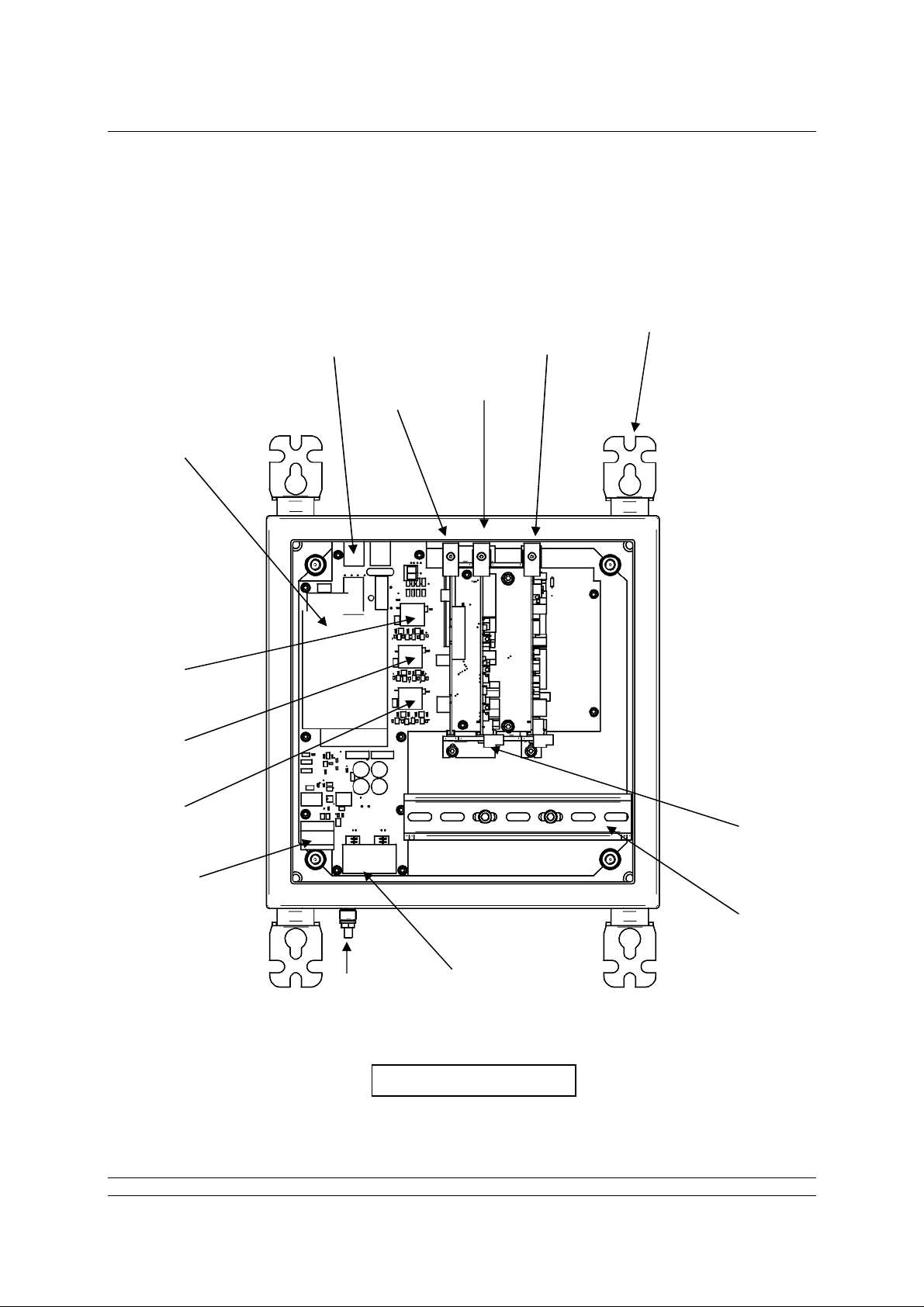
KNOW YOUR MASTER STATION
Power
Supply
Host
Ethernet
Port 3
Host
Ethernet
Port 4
Service
Ethernet
Port
Alarm and
ESD
Terminals
Power
Connector
Current Loop
CPU
Module
option
Future
option slot
Mounting
Brackets
Current
Loop
Connector
DIN Rail
Earth
Stud
2 of 82 Publication S703E V1.1 Issue 06/09
Host Comms Serial
Ports 1 and 2
View with door open
Page 3

Contents
Contents:
KNOW YOUR MASTER STATION.............................................................................2
INTRODUCTION.........................................................................................................5
1. MOUNTING AND CONNECTING THE MASTER STATION..............................7
1.1 Mechanical Fixing...................................................................................................................7
1.2 Serial Comms Connections ...................................................................................................8
1.3 Ethernet Comms Connections ..............................................................................................8
1.4 Power Connector and Fuse....................................................................................................8
1.5 ESD and Alarm Output Connector........................................................................................9
1.6 Current Loop Connections.....................................................................................................9
2. THE FIELD NETWORK....................................................................................11
2.1 Loop Checks..........................................................................................................................11
2.1 Loop Checks..........................................................................................................................12
2.2 Connecting Up.......................................................................................................................12
3. SORTING OUT THE SERIAL COMMS LINKS.................................................15
3.1 Setting Port 1 and 2 for RS232 or RS485............................................................................15
3.2 When to Use RS232 ..............................................................................................................17
3.3 When to Use RS485 ..............................................................................................................17
4. USING ETHERNET HOST COMMS.................................................................19
4.1 Setting-Up the Ethernet Comms..........................................................................................19
5. THE INTERNAL WEB PAGES.........................................................................21
5.1 Making an Internet / intranet Connection...........................................................................21
5.2 Connecting a Laptop Directly to the Master Station .........................................................21
5.3 5.3 Adjusting the Network Settings of the Laptop / PC....................................................21
5.3 5.3 Adjusting the Network Settings of the Laptop / PC.....................................................22
5.4 Web Page Structure..............................................................................................................23
5.4.1 User Levels.........................................................................................................23
5.4.2 Overall Web Page Layout...................................................................................23
5.5 The Web Pages in Detail.......................................................................................................25
5.5.1 Log In Screen .....................................................................................................25
5.5.2 Master Station ....................................................................................................25
5.5.2 Master Station ....................................................................................................26
5.5.3 View Configuration .............................................................................................28
5.5.4 System Diagnostics............................................................................................29
5.5.5 Master Station Data Logger................................................................................30
5.5.6 Master Station Host Analyser.............................................................................32
5.5.7 Pakscan 2 Loop Diagnostics..............................................................................33
3 of 82 Publication S703E V1.1 Issue 06/09
Page 4

P3F - Pakscan Master Station Technical Manual
5.5.8 Option Card Event Logger..................................................................................36
5.5.9 FCU Menu ..........................................................................................................37
5.5.10 FCU Control - IQ/IQT Actuator...........................................................................38
5.5.11 FCU Control - Integral Actuator..........................................................................43
5.5.12 FCU Control - Flowpak Actuator.........................................................................47
5.5.13 FCU Control - General Purpose Field Unit.........................................................49
5.5.14 FCU Control - Other Field Units.........................................................................52
5.5.15 Admin..................................................................................................................54
5.5.16 Users ..................................................................................................................54
5.5.17 Masterstation Config...........................................................................................57
5.5.18 Host Port Configuration......................................................................................61
5.5.19 Alarms.................................................................................................................64
5.5.20 Time....................................................................................................................66
5.5.21 General...............................................................................................................67
5.5.22 Network...............................................................................................................68
5.6 Setting Up the Master station Configuration Using the Web Pages................................70
5.6.1 Master Station Set-up page................................................................................70
5.6.2 Option Module Set-up (including host comms protocols)...................................72
5.6.3 Host Port Settings...............................................................................................72
5.6.4 Setting the IP Address........................................................................................73
6. MAKING THE SYSTEM WORK .......................................................................75
6.1 Commissioning the System.................................................................................................75
6.2 Monitoring and Controlling the Actuators..........................................................................76
GENERAL SAFETY INFORMATION........................................................................79
4 of 82 Publication S703E V1.1 Issue 06/09
Page 5
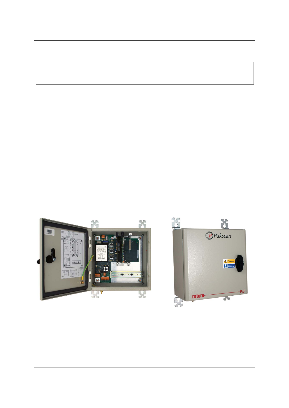
Introduction
This manual relates to Pakscan P3F Master Stations
fitted with PS720 Current Loop modules
INTRODUCTION
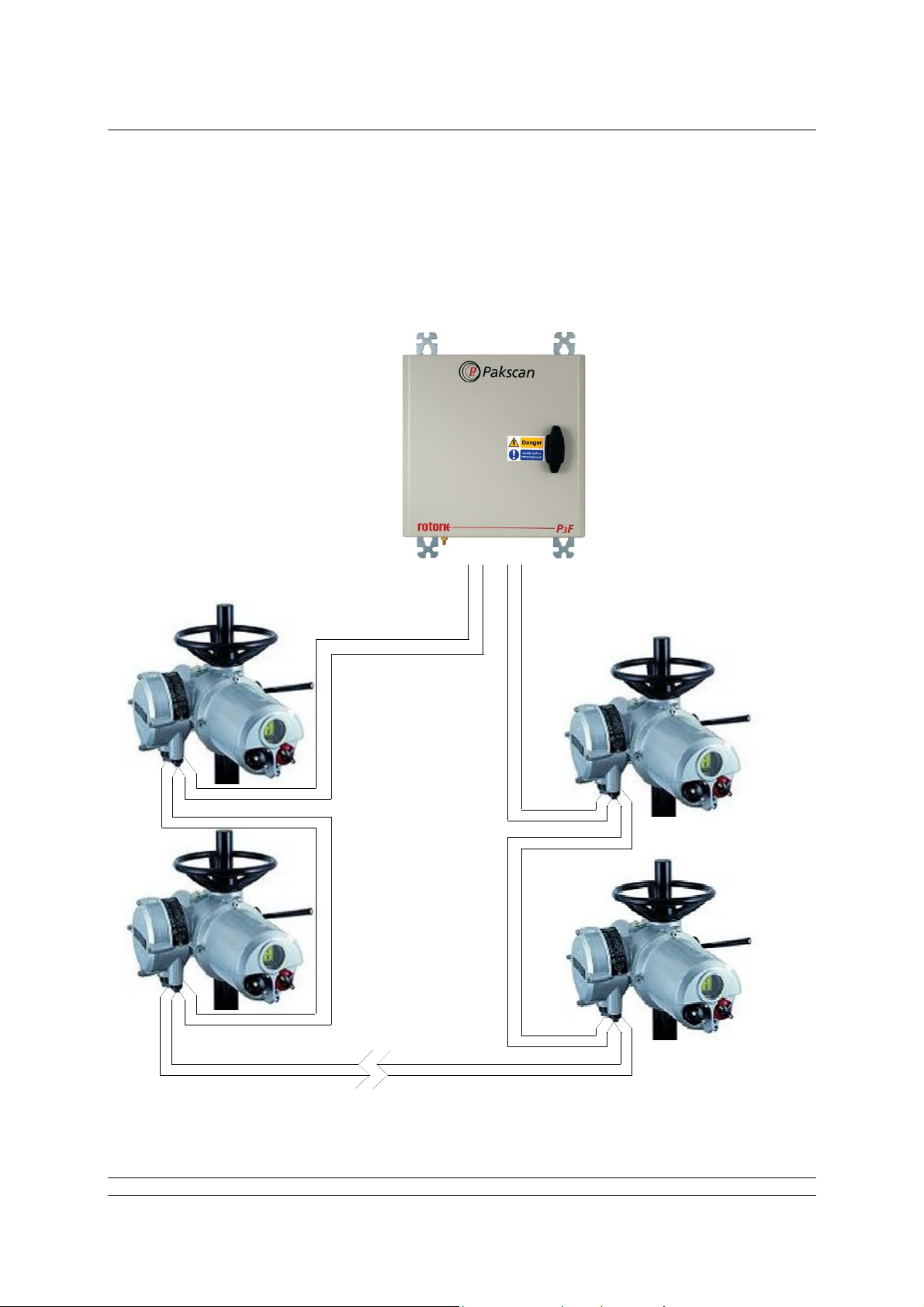
Pakscan 3 is the latest network control system from Rotork. The Pakscan P3F master station
encompasses the P3 technology in a master station specifically designed for mounting in remote
locations. The P3F enclosure protects the electronics within to IP65 standards and is suitable for use
in those locations where more conventional equipment cannot be located. Compared to the P3, the
P3F is simplified to include only those features demanded by smaller and simpler application s . It is a
single channel system capable of supporting up to 32 actuators or other field units.
Most types of Rotork actuator can be connected to the Pakscan current loop provided they are fitted
with the necessary field unit. Information on the respective actuator field units can be found in the
appropriate manuals. In this guide, the type of actuator is not considered, though reference is made to
both the Integral and IQ actuator types of field unit. The type of field unit does not affect the setting up
of the system.
The P3F master station is supplied as a stand alone unit ready for connection to the actuators and
host control system.
Fig 1: The Pakscan P3F Master Station
5 of 82 Publication S703E V1.1 Issue 06/09
Page 6

P3F - Pakscan Master Station Technical Manual
(This page is intentionally blank)
6 of 82 Publication S703E V1.1 Issue 06/09
Page 7
Mounting the Master Station
1. MOUNTING AND CONNECTING THE MASTER STATION
Before fixing the master station in its permanent location, it may be more convenient to set the
comms link switches as discussed in section 3.
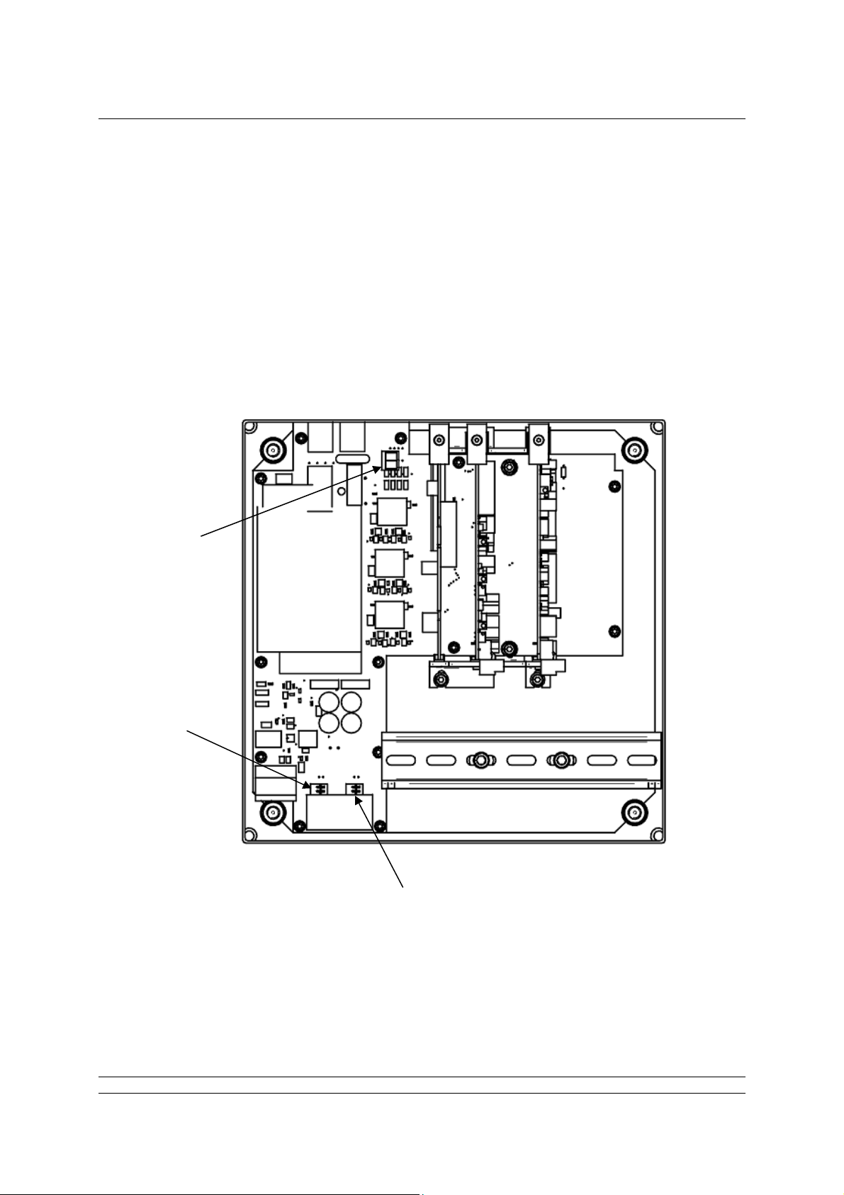
The Pakscan P3F master station provides front access for all the user connections including power
feed and the field loop wires to the Current Loop module (PS720). The host communication u se s
screw terminal connections for the serial comms and RJ45 connections for the Ethernet links.
The field wiring for the loop and the master station alarms is taken to screw terminals on plug
in connectors that are fitted from below their appropriate module.
Power wiring is connected using a 3-way plug-in connector with screw terminals in the top of
the master station main circuit board.
Serial comms ports 1 and 2 (RS232 or RS485) connect to an 8-way plug-in connector with
screw terminals on the bottom of the main circuit board.
Ethernet connections use RJ45 connectors on the main circuit board. The service port
connector is intended for connection to a service laptop computer. Host ports 3 and 4 are for
permanent Ethernet connections.
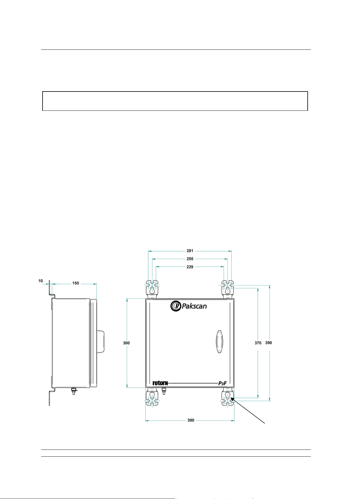
1.1 Mechanical Fixing
.
All dimensions in mm
Hinge on left side of
enclosure
Holes for M8
fixing bolts
Fig 2: Pakscan 3F surface mounting dimensions.
7 of 82 Publication S703E V1.1 Issue 06/09
Page 8

P3F - Pakscan Master Station Technical Manual
Room should be left around the enclosure for all the connections and cables, allowing for suitable
bending radius on each lead. Power wiring should be suitably fused or protected with a miniature
circuit breaker (MCB) external to the master station.
The master station should be mounted on a flat surface using the mounting brackets provided. It
should be located in a way that permits easy opening of the front door and access to the internal
connectors and modules.
1.2 Serial Comms Connections
The serial data connections are via the Serial Comms terminal block located on the main circuit board
below the power supply and to the left of the DIN rail. This connector has screw terminals and plugs in
to the mating part fixed on the circuit board. The terminal connections are shown below.
Port 1
Port 2
1
2
3
4
5
6
7
8
Terminal
1 TX
2 RX Data 3 GND GND
4
5 TX
6 RX Data 7 GND GND
8
Fig 3: Serial Comms connector terminal functions
RS232
Connections
Port 1
Data +
Port 2
Data +
RS485
Connections
With RS485 it is possible to arrange a multi-drop data highway for the serial communications,
whilst RS232 must be single point comms.
1.3 Ethernet Comms Connections
Each Pakscan P3F master station has 3 x RJ45 Ethernet connectors for the host communication ports
and the service port. These are marked Port 3 and Port 4 (host communication ports) and Port 5
(service port). A portable computer (laptop) should be connected to Port 5, the service port, to set up
the P3F. Standard Ethernet shielded patch cables should be used with these ports.
1.4 Power Connector and Fuse
The Pakscan P3F has its own internal power supply and a three-way screw terminal connector at the
top of the main circuit board is provided to allow the mains power (85 to 265V AC – 47 to 63 Hz) to be
connected. The master station power fuse is located just below this connector and should be 250V 1A
fuse. For the 24V DC version the same three-way connector is used.
8 of 82 Publication S703E V1.1 Issue 06/09
Page 9

Mounting the Master Station
Power
1
2
3
1 N (Neutral) 0 V
2 L (Line) 24 V
(85-265V ac)
Terminal ac Connection
dc Connection
(18-36V dc)
3 E (Earth) Earth
Fig 4: Power connector terminal functions
1.5 ESD and Alarm Output Connector
There is a removable screw terminal connector plugged into the main circuit board of the P3F master
station for the connection of ESD hard-wired inputs and for connection to the internal alarm relay
contacts, when required. (On most systems these terminals will not be used; in which case a hardwired link between pins 4 and 5 should be added.)
PS710
CONNECTOR
1
2
Alarm
3
4
5
Emergency
Shutdown
Terminal Function
1 Alarm (common)
2 Alarm (normally closed)
3 Alarm (normally open)
4 Emergency Shutdown
5 Emergency Shutdown
Note that the relay is shown in the ‘Alarm Active’ or ‘power removed’ position.
Fig 5: Alarm/ESD connector terminal functions
1.6 Current Loop Connections
A removable screw terminal connector is located in the bottom of the Current Loop Module for the
connection of the Pakscan IIE current loop to the field mounted actuators.
Terminal Function
1 Port B In
2 Port B Out
3 Port B Screen
4 Port A In
5 Port A Out
6 Port A Screen
Fig 6: Current Loop connections
9 of 82 Publication S703E V1.1 Issue 06/09
Page 10
P3F - Pakscan Master Station Technical Manual
Power
Connector
Ethernet
Ports
Fuse
Current
Loop
Hard Wired
ESD
Serial
Ports
Fig 7: View of the Pakscan P3F master station showing the Connectors and Fuse
10 of 82 Publication S703E V1.1 Issue 06/09
Page 11
Field Network
2. THE FIELD NETWORK
The Pakscan current loop field network must be correctly cabled and connected to the master station.
The values of the field loop resistance and capacitance must be known to determine the loop speed
that can be used. If these are not known then the LOWEST loop speed must be set in each actuator
and the master station to ensure some field network connectivity.
Port A
OUT = Term'l 5
IN = Term'l 4
Up to 32 actuators
per loop
Current loop
- up to 2 0 km
Port B
IN = Te rm' l 1
OUT = Term'l 2
Fig 8: Pakscan P3 Network
11 of 82 Publication S703E V1.1 Issue 06/09
Page 12

P3F - Pakscan Master Station Technical Manual
2.1 Loop Checks
The most common errors in installing the system occur on the field wiring.
Loop Continuity
With all the field units connected, but none of them powered up, check the continuity of the 2
cores of the cable and measure its resistance.
Screen Continuity
Make sure that the screen is isolated from the loop cores and that the screen is continuous.
Ensure the screen is connected to a signal earth bar at only one point or to terminals on the
loop driver plug; 3 linked directly to the enclosure earth and 6 linked to the enclosure earth via
an internal capacitor. Both the screens must be connected to the terminals provided, so as to
ensure the product meets the European Directive on EMC.
Cable Capacitance
The capacitance between the cores, and to the screen, is critical to the system performan ce.
Too high a capacitance for the selected loop baud rate will result in poor communications, or
even communication failure.
Maximum Loop Speed
The cable resistance and capacitance must not exceed the permitted maximum values for each
communication speed. The limiting values of R and C for each speed will depend on the
number of field units actually connected. The following table gives the total figures for systems
including the capacitance of the field units. Deduct 2.2nF for each field unit to determine the
maximum cable capacitance allowed at each speed.
Baud Rate R max (ohms)
110 500 4.5
300 500 2.1
600 500 1.54
1200 500 0.6
2400 500 0.3
C max (μF)
Each field unit will add a capacitance of 2.2nF (0.0022µF)
The C max figure given is the maximum value for the network capacitance
including the field unit capacitance.
2.2 Connecting Up
Once the checks are complete, connect the Loop Cables to the PS720 Current Loop module. At this
point leave the actuators all without power except for the one furthest from Loop Port A.
Refer to section 6 for commissioning a Pakscan system.
12 of 82 Publication S703E V1.1 Issue 06/09
Page 13

Field Network
SERIAL
PORT 1
SERIAL
PORT 2
ETHERNET
PORT 3
ETHERNET
PORT 4
MAINS
SUPPLY
LNE
3
12
POWER
SUPPLY
PROCESSORS
AND
COMMUNICATIONS
ETHERNET PORT 5
(CONFIGURATION)
PS 720 MODULE
(CURRENT LOOP
CONTROLLER)
5
4
3
2
ALARM
1
Screen
6
Port A OUT
5
Port A IN
4
Screen
3
Port B OUT
2
Port B IN
1
EMERGENCY
SHUTDOWN
Actuator Terminals
A
SIGNAL EARTH BAR
If there is a signal earth bar, connect the
screen on one side only to the bar
BC SCR
A
A
c
t
u
a
C
t
o
r
T
B
e
r
m
S
i
C
n
a
R
l
s
Actuator Terminals
ABCSCR
Note: If there is no hard-wired ESD requirement, a shorting link must be fitted across pin 4
and 5 of the 5 pin plug.
Fig 9: Pakscan P3F Current Loop System Block Diagram
13 of 82 Publication S703E V1.1 Issue 06/09
Page 14

P3F - Pakscan Master Station Technical Manual
(This page is intentionally blank)
14 of 82 Publication S703E V1.1 Issue 06/09
Page 15
Serial Comms Links
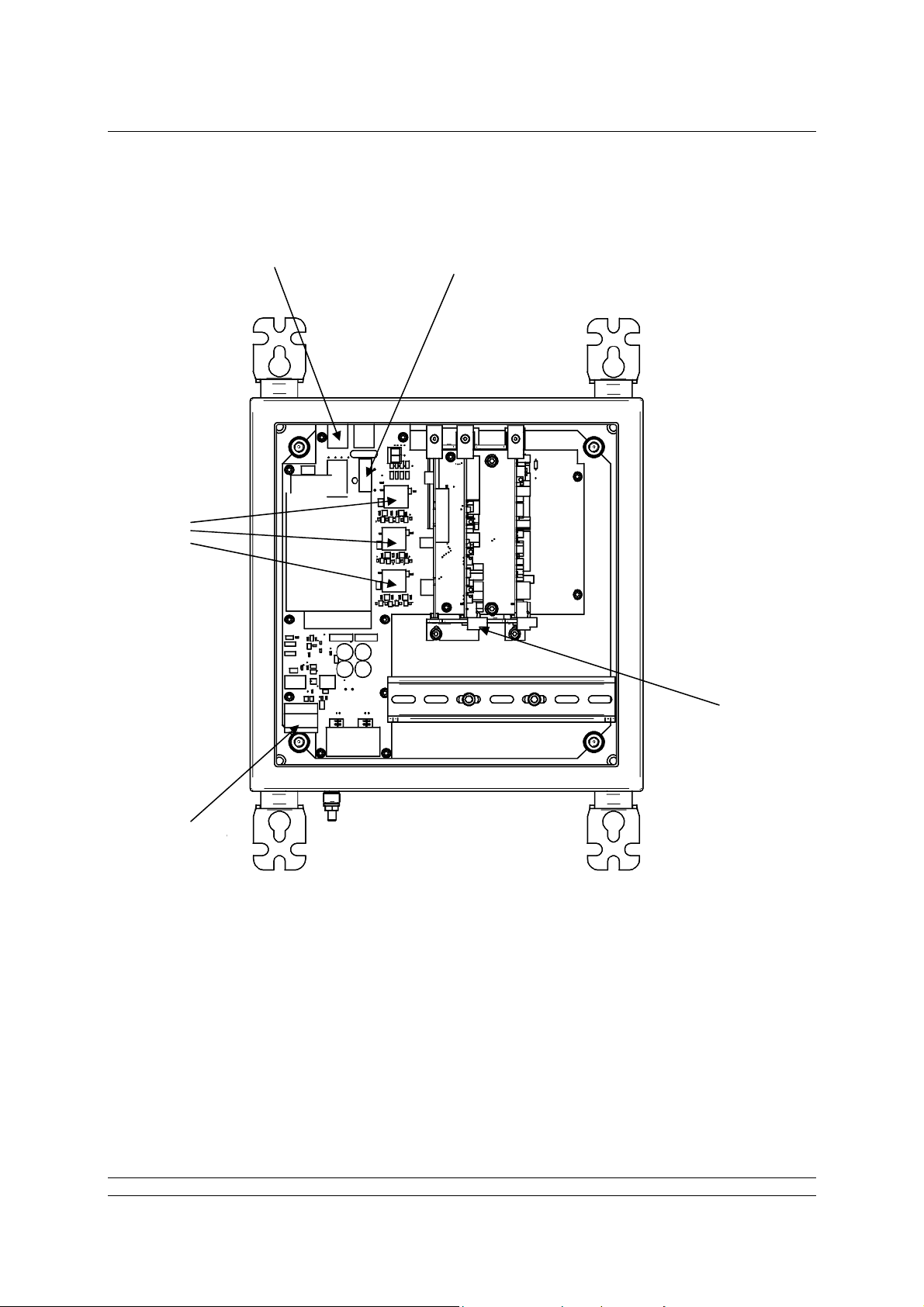
3. SORTING OUT THE SERIAL COMMS LINKS
The Pakscan P3F CPU module has two serial ports. Each of these is configurable for RS232 or
RS485. Where redundant communications to the host system using serial comms is required, then
two RS485 connections are often used.
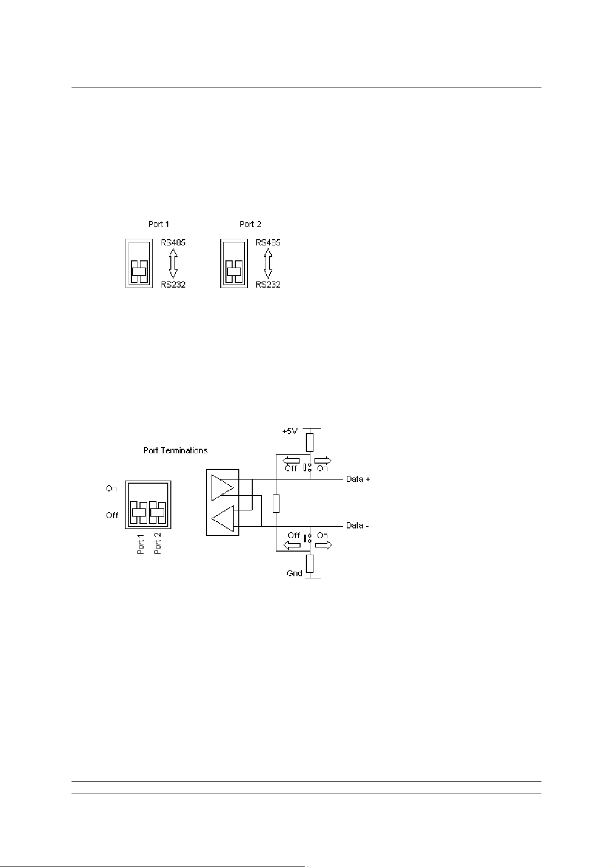
3.1 Setting Port 1 and 2 for RS232 or RS485
The main circuit board has DIP switches for setting the type of serial port that is presented at the port
terminal block.
Select RS485
Termination
Select Port 1
Function
Fig 10: Pakscan P3F Serial related switches
Select Port 2
Function
15 of 82 Publication S703E V1.1 Issue 06/09
Page 16
P3F - Pakscan Master Station Technical Manual
Port Function
The two DIP switches allow each port to be selected between RS 232 and RS485. For RS485
slide the appropriate Port switch up, for RS232 they should be down.
Each of the two ports may be set independently.
Fig 11: Port Function Switches shown in RS232 position
Port Termination Resistors
The two DIP switches are used to connect end of line termination resistors and biasing re sistors
to the RS485 network. All RS485 network highways should be terminated at both ends of the
highway. Each port can be terminated independently.
1k
120
1k
Fig 12: Port Termination Switches shown in Off position
16 of 82 Publication S703E V1.1 Issue 06/09
Page 17
Serial Comms Links
P
P
F
P
P3F
P
P
F
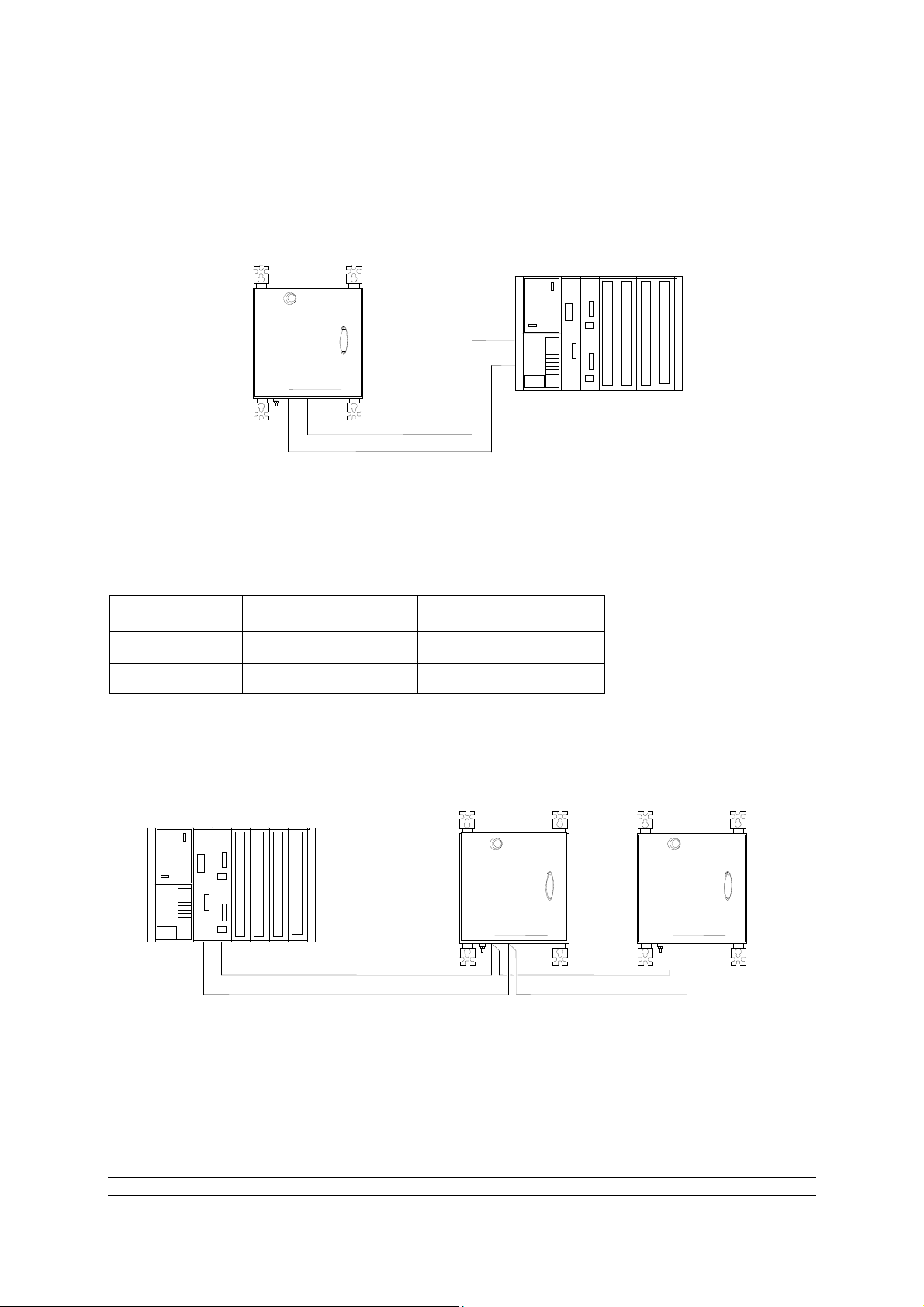
3.2 When to Use RS232
Pakscan P3F Master Station
PLC
Pakscan
3
rotork
3
Highway 1 – RS232
Highway 2 – RS232
Fig 13: RS232, dual highway, from P3F master station to PLC
When the host PLC or DCS is located near to the Pakscan P3F master station, RS232 comms can be
used with single point to point links. Either Port 1 or Port 2 can be used, though most users would use
Port 1. Two links can be used if redundant communications are required.
For RS232 on - Port Terminations RS232 RS485
Port 1 Off (Down) RS232 (Down)
Port 2 Off (Down) RS232 (Down)
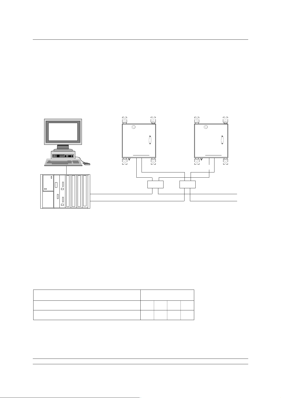
3.3 When to Use RS485
PLC
Pakscan P3F Master Stations
Pakscan
3
Pakscan
3
Fig 14: RS485, dual highway, from P3F master stations to PLC
Highway 1 - RS485
Highway 2 - RS485
rotork
rotork
3
When there are several Pakscan P3F master stations to be connected to the PLC, or the distance
between the Host and the master station is more than 20 metres, an RS485 highway will be best. The
highway will require a multi-drop configuration, as shown on the diagram. The screw connectors in
17 of 82 Publication S703E V1.1 Issue 06/09
Page 18

P3F - Pakscan Master Station Technical Manual
the master station make this simple to achieve. When a multi-drop connection is made, care must be
taken to ensure that the cable is not broken if a master station is disconnected.
The master station supplies port termination resistors for each port, which can be enabled where
required.
For RS485 on - Port Terminations RS232 RS485
Port 1
Port 2
Off (Down)
On (Up)
Off (Down)
On (Up
RS485 (Up)
RS485 (Up)
18 of 82 Publication S703E V1.1 Issue 06/09
Page 19
Ethernet Comms Links
4. USING ETHERNET HOST COMMS
Pakscan P3F master stations come complete with two Ethernet ports for connection to host DCS or
PLC systems. A third Ethernet port is also available for connection to a laptop computer for
configuration purposes. The master station is ready to use with Ethernet and Modbus TCP protocol for
the DCS to access data and control the actuators on the field network. The IP address is already set
and can be changed during setting up the master station
Pakscan
P
3
rotork
PLC
Port 3 Port 4 Port 3
Ethernet Highway 1
Ethernet Highway 2
Fig 15: Ethernet, dual highway, from P3F master station to PLC
4.1 Setting-Up the Ethernet Comms
Pakscan 3F Master Stations
Pakscan P3F Master Stations
P3F
Switch
Switch
rotork
Pakscan
P
3
P3F
Port 4
Ethernet connections require 10BaseT or 100baseT Ethernet Switches to connect the system
together. Patch cords connect the ports on the master to the Switches. Independent highways are
possible by using separate switches on each highway.
The Pakscan P3F master station defaults to the same IP address on both the ports. It is possible to
change the IP address, but the two ports always have the same address.
DHCP Static
Default IP address 10 200 1 1
Subnet mask 255 255 255 0
19 of 82 Publication S703E V1.1 Issue 06/09
Page 20

P3F - Pakscan Master Station Technical Manual
The recommended highway organisation is:
Use two main data highway bus’s, each of which connects to all the master stations.
The master is left with a Static DHCP port setting.
The master station can serve up to 10 simultaneous host connections.
With this arrangement either PLC port can always communicate with the master station and the
devices on the loop. Heartbeat data requests on the second highway will always be acknowledged
with a response.
20 of 82 Publication S703E V1.1 Issue 06/09
Page 21

The Web Browser
5. THE INTERNAL WEB PAGES
The P3F master station includes a set of Web pages that may be remotely accessed via Ethernet.
They can be used for setting up the system, examining the system for any faults or alarms and also for
controlling the actuators on the network (provided the Interlock permission is set to allow this feature).
If the master station is connected to an Ethernet Network it will act as a server and any computer
within that network can connect to the master station. The master station can also be configured and
the field network set up by using these web pages. The host system or PC connected via the Ethernet
Network or directly will need a web browser such as Internet Explorer to access the master station
web pages
5.1 Making an Internet / intranet Connection
Connect the master station to an Ethernet host as described in section 4, or connect via a suitable
router to the internet / intranet. A laptop or PC can be directly connected to port 3 or 4 or to the
configuration connector, if there is no network connection available. Details of directly connecting a
laptop are contained in the section on setting up with a PC, below.
Start the browser and enter the IP address of the master station. The default address is 10.200.1.1, so
the address is http://10.200.1.1. The browser will then access the master station and bring up the
opening page of the master station. In order to log in as a verified user enter a user name of admin
and a password of admin. (These default names should be altered as soon as convenient to prevent
unauthorized access to the system.)
Default IP address 10 200 1 1
Default User admin
Default Password admin
Once entry to the web pages has been made, if no changes to the display or information is made for
10 minutes, the system will automatically log out and the user/password must be re-entered.
5.2 Connecting a Laptop Directly to the Master Station
The simplest direct connection to the master station is by using the Ethernet port on the front of the
main pcb. A standard Ethernet patch cable can be used to link the two directly. The connector will
accept either a standard patch cable or a direct link cable that has a twist between the transmit pair
and receive pair in the cable. A permanent PC connection can also be made directly to the main
Ethernet connector (port 3 or 4). In order to establish a connection it may be necessary to adjust the
settings of the Laptop Internet connection.
5.3
Fig 16: Connecting a Laptop to the Pakscan P3F
21 of 82 Publication S703E V1.1 Issue 06/09
Page 22
P3F - Pakscan Master Station Technical Manual
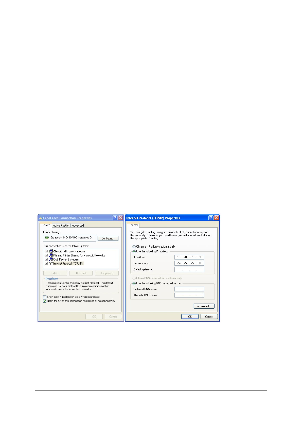
5.3 Adjusting the Network Settings of the Laptop / PC
Ensure nothing is connected to the Ethernet port of the laptop / PC.
Open the Control Panel and select Network Connections.
In the ‘Network Connections’ window, double-click on the ‘LAN or High Speed Internet’ icon
and the ‘Local Area Connection Status’ window will open.
Click on the ‘Properties’ button, and a second window will open. Select ‘Internet Protocol
TCP/IP’ and click on the ‘Properties’ button in this window.
The ‘Internet Protocol TCP/IP Properties’ window will open. Next change the setting to force
the Laptop to adopt a fixed IP address and enter an address for the Laptop / PC of 10.200.1.3
and a subnet mask of 255.255.255.0. Click on the OK button and the window will close.
Click OK on the ‘Local Area Connection Properties’ window and then Close the status windo w.
Finally, close the Network Connections window and the Control Panel.
It may be necessary to reboot the PC to be sure that the new settings take effect correctly.
Connect the cable between the PC and the Pakscan master station.
Fig 17: Changing the Network Connections TCP/IP Properties
22 of 82 Publication S703E V1.1 Issue 06/09
Page 23

The Web Browser
Start the browser and enter the IP address of the master station. The default address is 10.200.1.1, so
the address is http://10.200.1.1. The browser will then access the master station and bring up the
opening page of the master station. In order to log in as a verified user, enter a username of admin
and a password of admin.
Note that if the IP address of the master station has been changed from the defaults, then the settings
above will not work and have to be modified to suit the actual settings.
5.4 Web Page Structure
The web pages have three access levels, each requiring a password with the correct level set. A user
enters the web server with a particular degree of access to the functions of the server and the master
station.
5.4.1 User Levels
Access Level Function
Allows access to read master station status and settings,
Lowest level Read
plus the option card status and settings and the actuator
and field unit status on the option card network. No
commands or alterations to the system are permitted.
As for read access with the addition of the ability to issue
Write
network commands, swap masters and command
actuators on the option card network to change position.
As for the two lower levels plus the ability to configure the
master station, option cards and all system settings. Set
Highest Level Administrator
and remove user names and passwords, set alarm
reporting parameters, change system addresses and test
system communications.
The Administrator level sets all other user names and passwords. As soon as the system is set up, the
default password should be changed.
5.4.2 Overall Web Page Layout
The web pages are organised using a menu structure with the primary menu on the top of each page.
Within a page there are other controls for parameter alteration or to reveal extended information on
the topic of the particular page.
Navigation between the pages is by selecting another topic on the main menu.
If there is no activity with the mouse to change the display or update the information or selection for 10
minutes the system automatically logs out the user and the username and password must be reentered to continue using the pages.
23 of 82 Publication S703E V1.1 Issue 06/09
Page 24

P3F - Pakscan Master Station Technical Manual
Log In
Masterstation
View
Configuration
System
Diagnostics
Master Station
datalogger
Host Analyser
Option Diagnostics
Network
Diagnostics
Option Event Log
FCU Menu
FCU 1 to 32 control
and data
Admin*
Users
* requires Admin level log in
Master station and
Option Configuration
Host Port
Alarms
Time
General
Network
Fig 18: Web Page Menu Layout
24 of 82 Publication S703E V1.1 Issue 06/09
Page 25

The Web Browser
5.5 The Web Pages in Detail
5.5.1 Log In Screen
Fig 19: Log In Screen
The first screen is the Log In screen on which the user must enter a Username and Password.
Username - a case sensitive identification for an individual or group used to give access to
the system. Usernames are listed for administrators to see on the ‘Add User’ page.
Password - the case sensitive confirmation required before a use rn ame is accepted by the
system. Passwords are not listed on any page in the system and cannot be retrieved, even at
the administrator level.
Select the box with a mouse and enter the appropriate name or password, then click on the login
button. The system will move to the next page if the login is accepted, if it fails the data is cleared from
the boxes and must be re-entered correctly in both boxes before access is granted.
The default user name is admin and password is admin. (These default names should be altered as
soon as convenient to prevent unauthorized access to the system).
User name and
access level.
Menu of available screens to visit
(changes to blue when selected)
for Read and Write access levels.
Log out when finished
by clicking here
(changes to red when
Fig 20: Web Page Header Navigation
25 of 82 Publication S703E V1.1 Issue 06/09
Page 26

P3F - Pakscan Master Station Technical Manual
5.5.2 Master Station
Site Name
Tag Name
Status
Option Card 1
Status
Controls
Fig 21: Master Station Overview Page
This screen is accessible to Read, Write and Administration user levels.
The screen reports the current status of the master station and the option cards fitted. The coloured
lights show the condition of the associated parameter. Greyed out text and lights are not applicable or
else in a safe (normal) condition.
Master Station CPU Module
Site name : The name of the site where the system is located as entered during
configuration.
Tag name : The master station tag as entered during configuration.
Status
Module Health : Indicates the absence (green light) or presence (red light) of a fault on the
this CPU.
ESD Presence : Shows a yellow light if an Emergency Shut Down signal is active.
Alarm : Indicates the presence of an alarm (red light) somewhere on the system.
Option 1 - Pakscan 2 Loop Option Module
Loopback in : A blue light shows whilst the master station is reconfiguring the loop.
Progress
Loopback In use : A yellow light shows when the master station has detected a loopback fault
on the system.
26 of 82 Publication S703E V1.1 Issue 06/09
Page 27

The Web Browser
Auto Loopback : If a fault occurs on the network and an automatic reconfiguration of the
loop occurs, a yellow light is shown here.
Common Field : A red light shows if any field unit on the network has an alarm bit present.
Unit Alarm
Common : A red light shows if any actuator on the network is unavailable due to its
Actuator Alarm monitor relay having tripped.
ESD Active : If there is any Emergency Shut Down signal present on the system a red
light shows.
Controls - Not Available for Read level users
Network ESD : Click here to issue an ESD to all actuators connected to either option card.
The resulting action will depend on the individual actuator settings. A
confirmation screen appears to verify or cancel the instruction before the
action occurs.
27 of 82 Publication S703E V1.1 Issue 06/09
Page 28

P3F - Pakscan Master Station Technical Manual
5.5.3 View Configuration
Fig 22: System Configuration Overview Page
This screen is accessible to Read, Write and Administration user levels.
The screen shows the settings for the control of the option card network and the CPU control
capability, software fitted and various options selected. All of these settings can be modified, but only
by users with Administration level access. There are no controls on this page.
The settings are explained in the Master Station Configuration page section.
28 of 82 Publication S703E V1.1 Issue 06/09
Page 29

The Web Browser
5.5.4 System Diagnostics
Master Station CPU
Status
Controls
Option Card 1
Controls
Fig 23: System Diagnostics Page
This screen is accessible to Read, Write and Administration user levels.
The System Diagnostics screen shows an overview of the status of the fitted module and also
provides access to further information.
Master Station Diagnostics
Module Health : A green light shows if the module is operating correctly or a red light if
there is a fault.
Modbus/TCP : Indicates when Ethernet control using Modbus/TCP is present on either
activity Ethernet port.
Host port 1 : Indicates when there is active serial communication on comms port 1.
activity
Host port 2 : Indicates when there is active serial communication on comms port 2.
activity
Controls - Available to all user levels
MS datalogger : Reveals a pop-up showing a log of the activity on the master station and
the source of requests or commands received.
Host analyser : Reveals a pop-up with the data logger data and the additional controls
required for using the inbuilt data analyser for commands and data to the
host system.
Option 1 Diagnostics
Pakscan 2 Loop : Shows module type and status.
Option Health : Shows green light when healthy and red light if there is a fault on the
module.
Controls - Available to all user levels
Diagnostics : Reveals the diagnostic page for the option card fitted.
Event Log : Shows the option module event recorder.
29 of 82 Publication S703E V1.1 Issue 06/09
Page 30

P3F - Pakscan Master Station Technical Manual
5.5.5 Master Station Data Logger
Close pop up
Master Station
Events
Controls
Fig 24: Master Station Data Logger
This screen is accessible to Read, Write and Administration user levels.
The data logger displays Modbus instructions received by the master station to carry out com mands
such Alarm Accept or commands to move a valve. Each event is prefixed by a date and time and they
are listed in time order. They are followed by the source from which the command originated. Once full
the log rolls over and rewrites over the oldest events, the log is 1Mbyte in size.
Date and Time Modbus Message Message Source/Address
Fig 25: Data Logger Information
Date and Time
Formatted Day/Month/Year or Month/Day Year
Modbus Message
Standard Modbus RTU format for all ‘write’ messages
Message Source and Address
Ethernet : Ethernet input and IP address of the source.
RTU : Serial port 1 (RTU 1) or serial port 2 (RTU 2).
Webpages : Webpage Log In name and IP address.
30 of 82 Publication S703E V1.1 Issue 06/09
Page 31

The Web Browser
Controls - Available to all user levels
Print : Prints the logger to a printer attached to the PC.
Save : Saves the logger data to a file on the PC.
The saved file is of the type cmdlog.log and can be opened in the Notepad
on the PC. It can also be imported into a spread sheet such as Excel for
analysis as required.
Refresh : Updates the file with any new data.
Fig 26: Saving the log file
31 of 82 Publication S703E V1.1 Issue 06/09
Page 32

P3F - Pakscan Master Station Technical Manual
5.5.6 Master Station Host Analyser
Close pop up
Analyser Events
Controls
Fig 27: Host Analyser Screen
This screen may be used by Administration user level only.
The Host Analyser is a real time system analyser that can be used with either a Modbus RTU serial
data control source acting through one of the serial data ports (Port 1 or 2), or a Modbus TCP Ethernet
control source acting through the Ethernet port.
The analyser will record up to 100 messages (requests and responses) on the data line between the
two points. It is especially useful for debugging a host control system to ensure that messages are
correctly formatted and that the required control or data points are being accessed. In particular the
use of correct offsets in the Modbus protocol can be checked.
Controls - Available to Administration user level
RTU1 : Selects Port 1 host input.
RTU2 : Selects Port 2 host input.
ETH : Selects the Ethernet port host input.
Print : Prints the analyser data to a printer attached to the PC.
Save : Saves the analyser data to a file on the PC.
Refresh : Updates the file with any new data.
32 of 82 Publication S703E V1.1 Issue 06/09
Page 33

The Web Browser
5.5.7 Pakscan 2 Loop Diagnostics
Network
Controls
Network FCU Map
Fig 28: Pakscan 2 Loop Diagnostics
This screen is accessible to Read, Write and Administration user levels.
The Pakscan 2 Loop Diagnostics screen gives diagnostic information on the two-wire loop option card
and the network connected to it. The top part of the screen shows the information about the option
card itself whilst the lower part shows the loop map. This is the order in which the field units on the
two-wire loop are connected. It also shows the device type and tag name for each address and
position.
Network Diagnostics
No. Of Devices : This is the number of field units that are expected to be located on the
On Network network. It is the highest address that the network will scan up to when
locating field units. All field units are assumed to be consecutively
addressed.
No. Of FCUs : This is the total number of field units located on the network. If all the field
Found units are powered on and connected the number will equal the No. of
devices on the network above.
Configuration : This field shows any fault that exists on the network cabling and the stages
Status passed through as network configuration takes place.
33 of 82 Publication S703E V1.1 Issue 06/09
Page 34

P3F - Pakscan Master Station Technical Manual
During configuration the following sequence can be displayed -
1. Wait for Loopbacks 1 (first wait for loopbacks to come on)
2. Find FCUs on Port A (finding FCUs on port A)
3. Test Loop (testing for complete loop)
4. Find FCUs on Port B (finding FCUs on port B)
5. Wait for Loopbacks 2 (second wait for loopbacks to come on)
6. Loopbacks off on A (removing loopbacks from port A)
7. Loopbacks off on B (removing loopbacks from port B)
(The normal sequence for a fault-free loop would be 1, 2 and 3. A
sequence for a break in the loop anywhere except at port A or port B,
would be 1 to 7. Some of the phases may be very quick, particularly at
higher baud rates, and so may not be seen on the browser display.
Whilst the configuration is taking place, the master station web page shows
a blue light and ‘Loopback in Progress’ on the Option module.
If the configuration process detects a fault on the loop and switches on the
loopback circuits of two field units, the master station web page shows
‘Loopback in Use’ and illuminates the yellow light.
Last Network : The loop can be reconfigured for a number of reasons and this field will
Reset Initialised show the cause of the last reset/reconfigure that occurred.
By The possible reasons are:
Power on Reset - loop configured because the master station
powered up.
Fault Found - fault detected on the loop whilst it was running
without loopbacks present.
Fault Found A - fault detected on the A side of broken loop whilst
running with loopbacks on.
Fault Found B - fault detected on the B side of broken loop whilst
running with loopbacks on.
Reset Command - loop Reconfigure command entered from keypad
or serial port.
Return wire fault - fault detected in the return current path whilst the
loop was running at double speed.
Doubling failed - fault detected after loop assumed double speed.
Network Fault : This field shows the type of fault detected that caused the loopback to
Type occur, or an addressing fault on the field units. The types are:
Zero Address - a field unit has been found with an address of
zero.
Address too High xx - a field unit has been found with an address
higher than that setup within the master station,
xx is the address.
Same Address xx - two field units found with the same address, xx is
the address
Loop Open Circuit - an open-circuit fault found on the loop.
Loop Short Circuit - a short-circuit fault found on the loop.
If two field units are found with the same address, or there is an address
outside the range of addresses expected (as set by No. of Devices on
34 of 82 Publication S703E V1.1 Issue 06/09
Page 35

The Web Browser
Network), the network will continue to operate and miss out the faulty field
units.
Loop Baud Rate : Shows the current speed selected. The speed can be 110, 300, 600, 1200,
or 2400 baud.
No. Of FCUs : This is the total number of field units connected to the option card Port A
On Side A and communicating via Port A.
No. Of FCUs : This is the total number of field units connected to the option card Port B
On Side B and communicating via Port B. Port B is only used if there is a loopback
present on the network.
Controls - Available to all user levels
Reset network : Causes the option card to reconfigure the two-wire network. This should be
used after a loop fault has been corrected.
Network Map
The map shows the order in which the field units have been identified and found by the option
card during the last loop reconfiguration process (reset). Each time the loop is reconfigured the
map is regenerated and repopulated. Any field unit that is not powered up at the time of
reconfiguration will be absent from the map.
Position : The position in the loop. Number 1 is nearest to Port A.
Address : The address of the field unit.
Failures : Shows a count of communication errors with the field unit. The count has a
range of 0 to 255, after which it rolls around to zero and it increments for
every communication error. The system will only announce a ‘Comms
failure’ when 3 successive tries have failed to locate the field unit. This
counter therefore reflects the communications condition and can be used
as an indicator of the health of the field unit to assess the probability of
failure in the future.
Type : The type of field unit depends on the actuator and function required.
Tag Name : The associated identification Tag assigned to this field unit.
35 of 82 Publication S703E V1.1 Issue 06/09
Page 36

P3F - Pakscan Master Station Technical Manual
5.5.8 Option Card Event Logger
Close pop up
Event Log
Controls
Fig 29: Option Card Event Logger
This screen is accessible to Read, Write and Administration user levels.
The event logger shows the last occurrence of the listed events and in the case of the ESD source,
where the signal originated.
Controls - Available to all user levels
Print : Prints the logger to a printer attached to the PC.
Save : Saves the logger data to a file on the PC.
Refresh : Updates the file with any new data.
36 of 82 Publication S703E V1.1 Issue 06/09
Page 37

The Web Browser
5.5.9 FCU Menu
Network
Controls
Fig 30: FCU Menu
This screen is accessible to Read, Write and Administration user levels.
The FCU Menu lists all the field units in address order (which may not be the same as the order in
which they connected together on the loop).
For each address, the Tag name and Type of field unit is listed. The Network column shows which
option card network each actuator is connected to, this will be Pakscan 2 for the two-wire loop option
card.
The next two columns show critical alarm conditions that will prevent remote control of the actuator.
An Alarm present will generally prevent operation whilst Comms Fail indicates that the actuator is no
longer in communication with the network.
The final column has Navigation controls to the individual FCU screens.
Controls - Available to all user levels
FCU Control : Click here to show the selected FCU individual control panel web page.
The different types of devices each have different screens and only the
relevant data and controls for each type are included on the screen,
together with a picture identifying the type.
When not in communication, the screen may still be visited, but the
actuator picture will have a large red cross over it to show that a problem
exists.
37 of 82 Publication S703E V1.1 Issue 06/09
Page 38

P3F - Pakscan Master Station Technical Manual
5.5.10 FCU Control - IQ/IQT Actuator
Navigation
Actuator picture
Controls
Fig 31: IQ and IQT actuator FCU Control
This screen is accessible to Read, Write and Administration user levels.
The IQ and IQT control screens are similar and show a picture to identify the actual type of actuator at
this FCU address.
The FCU Control screen shows a control and status page for the selected field unit and actuator. The
screen has information relating to the device, its current condition and system parameters. It also
includes the ability to change the actuator’s position by means of the control buttons. When not in
communication the screen may still be visited, but the picture has a large red cross over it to show a
lack of communications.
Address
Navigation
Refresh
Next Previous
Navigation between the field units is either by returning to the previous screen, or by using the
navigation buttons on this screen. Entering an address directly in the ‘Address’ box and clickin g
Refresh moves directly to the selected field unit.
38 of 82 Publication S703E V1.1 Issue 06/09
Page 39

The Web Browser
Identification
Tag name : Identification tag given for this device.
Address : Network address.
Type : Shows the identified actuator type as IQ (IQT on the IQT screen).
Network : The network to which this device is connected (Pakscan 2 for two-wire
loop).
Current Status
The real time status of the actuator is listed in this pane on the screen.
Auxiliary Input : Active or Inactive shows the status of the actuator Digital inputs.
1 to 4
Valve Position : Current position, closed, open or stopped mid position.
Actuator : Moving or stationary.
Running Direction : Opening or closing.
Loopback : Off or On.
Battery Status : OK or Low.
Alarm Status : No Alarm or Alarm.
Actuator Position
A bar graph shows the current actuator analogue position between 0 (closed) and 100% (open).
Instantaneous Torque
A bar graph shows the current torque value between 0 and 120%.
Controls
Parameters - Viewable by all user levels
Close pop-up
Fig 32: IQ Parameters (IQT Parameters similar)
39 of 82 Publication S703E V1.1 Issue 06/09
Page 40
P3F - Pakscan Master Station Technical Manual
Pop-up screen shows the settings for all the parameters relating to the IQ actuator field unit. For
users with Administration level rights the values can be edited and for the latest version field
units, the type of actuator can be modified. The parameters are used to determine the way in
which the actuator responds to commands and reports data. Information on how to set these
fields is contained in the actuator field unit manuals.
Controls
Save Settings : Edited fields may be saved, accessible by Administrator level users only
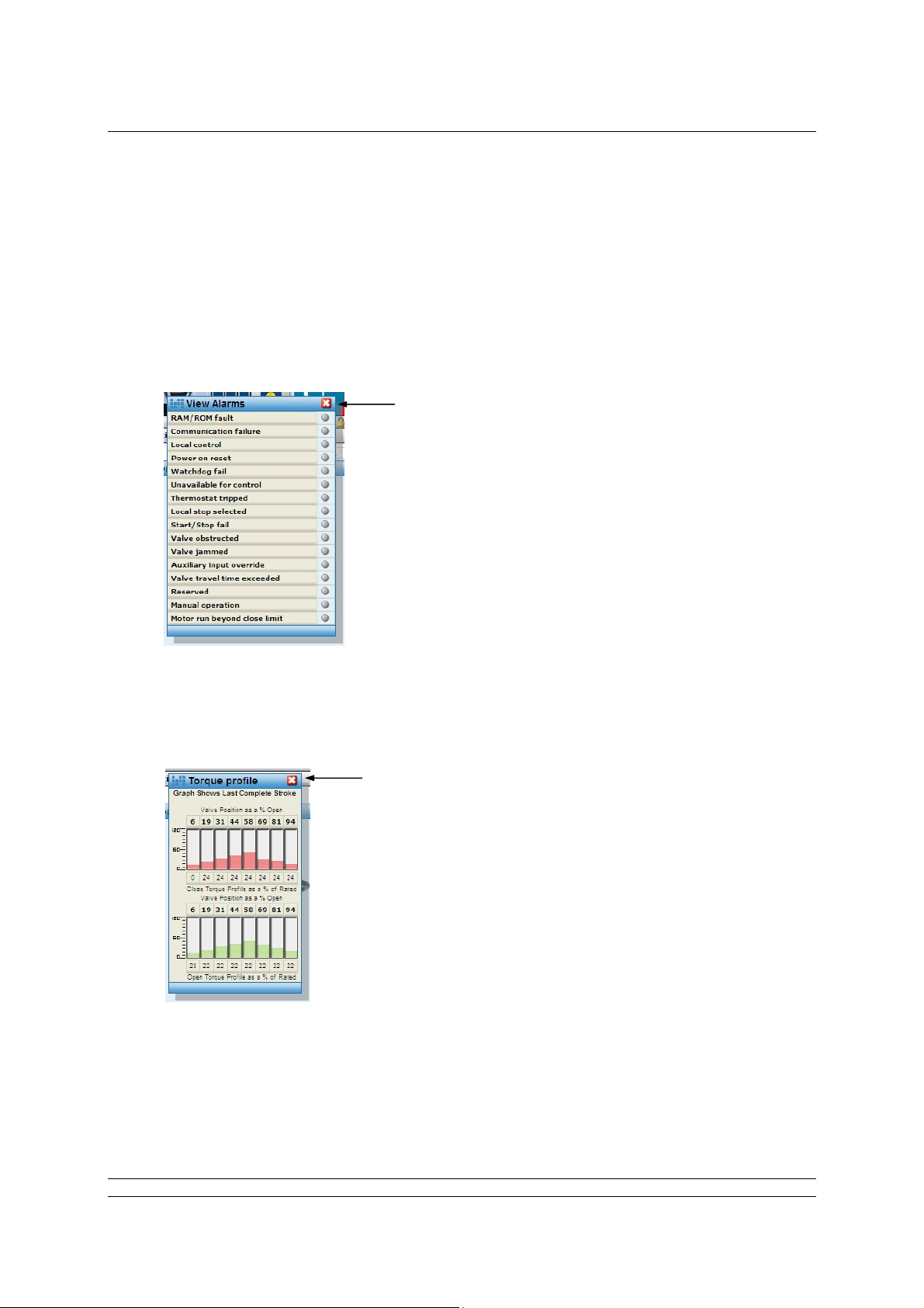
Show Alarms - Viewable by all user levels
Close pop up
Fig 33: IQ Alarms (IQT Alarms similar)
Pop-up screen shows the alarms on the actuator as red lights, grey is no alarm. Additional
information on the meaning of these alarms is contained in the individual field unit manuals.
Torque Profile - Viewable by all user levels
Close pop up
Fig 34: IQ Torque Profile (IQT Torque Profile similar)
Pop-up screen shows the last complete stroke torque profile generated by the actuator.
40 of 82 Publication S703E V1.1 Issue 06/09
Page 41

The Web Browser
Event Log - Available to all user levels
Close pop up
Controls
Fig 35: IQ FCU Event Log (IQT Event Log similar)
Pop-up screen showing a log of the last occasion on which the various control and alarm events
occurred. For commands, the source of the command is also given.
Remote selected - local remote selector in remote position.
Moving - actuator centre column moving.
Monitor Relay - monitor relay alarm.
Open Limit - open position limit switch.
Closed Limit - closed position limit switch.
Comms Failed - loss of network communication.
Thermostat - motor thermostat tripped.
Torque Tripped - torque limit level exceeded.
Manual move - actuator moved by the handwheel.
POR - power on reset.
Watchdog - Field unit watchdog alarm.
AUX OR - Auxiliary input present.
Start / Stop - Failure to respond to a remote control input.
MemF - FCU memory chip RAM or ROM fault.
EOT - Motor running at end of travel.
Network Open - open instruction over the control network.
Network Close - close instruction over the control network.
Network Stop - stop instruction over the control network.
Network ESD - ESD instruction over the control network.
Position / Time - last position control event.
Position / Time - last-but-one position control event.
Position / Time - last-but-two position control event.
41 of 82 Publication S703E V1.1 Issue 06/09
Page 42

P3F - Pakscan Master Station Technical Manual
Controls
Print : Prints the datalogger to a printer available to the PC.
Save : Saves the logger data to a file on the PC.
Actuator Controls - Available to Write and Administration user levels only
Open : command to open the valve fully.
Stop : command to stop the actuator in its present position.
Close : command to close the valve fully.
ESD : command to put the valve in its Emergency Shut Down position. (This can
be ‘stayput’ or move to either the open or closed position).
Pos DV : a slider control that is used to generate a setpoint position for the valve in
the range 0 - 100%.
All the controls have a confirmation pop-up so that the action has to be confirmed before it takes
place.
42 of 82 Publication S703E V1.1 Issue 06/09
Page 43

The Web Browser
5.5.11 FCU Control - Integral Actuator
Navigation
Actuator picture
Controls
Fig 36: Q actuator FCU Control
This screen is accessible to Read, Write and Administration user levels.
The Integral actuator FCU Control screen shows a control and status page for a Q type actuator. The
screen has information relating to the device, its current condition and system parameters. Control of
the actuator is permitted via the control buttons for users with write level access or higher. When not in
communication, the screen may still be visited, but the picture has a large red cross over it to show a
lack of communications.
Navigation
Previou
Addres
Next
Refres
Navigation between the field units is either by returning to the previous screen, or by using the
navigation buttons on this screen. Entering an address directly in the ‘Address’ box and clickin g
Refresh moves directly to the selected field unit.
Identification
Tag name : Identification tag given for this device.
Address : Network address.
Type : Shows the identified actuator type as Q.
Network : The network to which this device is connected (Pakscan 2 for two wire
loop).
43 of 82 Publication S703E V1.1 Issue 06/09
Page 44

P3F - Pakscan Master Station Technical Manual
Current Status
The real time status of the actuator is listed in this pane on the screen.
External Input : Active or Inactive shows the status of the input.
Valve Position : Current position, closed, open or stopped mid position.
Actuator : Moving or stationary.
Running Direction : Opening or closing.
Loopback : Off or On.
Alarm Status : No Alarm or Alarm.
Actuator Position
For actuators fitted with position feedback facilities, a bar graph shows the current actuator
analogue position between 0 (closed) and 100% (open).
Controls
Parameters - Viewable by all user levels
Close pop up
Fig 37: Q Parameters
Pop-up screen shows the settings for all the parameters relating to the integral field unit. For
users with Administration level rights the values can be edited.
Controls
Save Settings : Edited fields may be saved, accessible by Administrator level users only.
Show Alarms - Viewable by all user levels
Close pop up
Fig 38: Q Alarms
44 of 82 Publication S703E V1.1 Issue 06/09
Page 45

The Web Browser
Pop-up screen shows the alarms on the actuator as red lights, grey is no alarm. Additional
information on the meaning of these alarms is contained in the individual field unit manuals.
Event Log - Available to all user levels
Close pop up
Controls
Fig 39: Q FCU Event Log
Pop-up screen showing a log of the last occasion on which the various control and alarm events
occurred. For commands, the source of the command is also given.
Remote selected - local remote selector in remote position.
Moving - actuator centre column moving.
Monitor Relay - monitor relay alarm.
Open Limit - open position limit switch.
Closed Limit - closed position limit switch.
Comms Failed - loss of network communication.
Thermostat - motor thermostat tripped.
Torque Tripped - torque limit level exceeded.
Manual move - actuator moved by the handwheel.
POR - power on reset.
Watchdog - Field unit watchdog alarm.
AUX OR - Auxiliary input present.
Start / Stop - Failure to respond to a remote control input.
MemF - FCU memory chip fault.
EOT - Motor running at end of travel.
Network Open - open instruction over the control network.
Network Close - close instruction over the control network.
Network Stop - stop instruction over the control network.
45 of 82 Publication S703E V1.1 Issue 06/09
Page 46

P3F - Pakscan Master Station Technical Manual
Network ESD - ESD instruction over the control network.
Position / Time - last position control event.
Position / Time - last but one position control event.
Position / Time - last but two position control event.
Controls
Print : Prints the datalogger to a printer attached to the PC.
Save : Saves the logger data to a file on the PC.
Actuator Controls - Available to Write and Administration user levels only
Open : command to open the valve fully.
Stop : command to stop the actuator in its present position.
Close : command to close the valve fully.
ESD : command to put the valve in its Emergency Shut Down position. (This can
be ‘stayput’ or move to either the open or closed position).
Pos DV : a slider control that is used to generate a setpoint position for the valve in
the range 0 - 100%. Only available for actuators fitted with position
feedback facilities
All the controls have a confirmation pop-up so that the action has to be confirmed before it takes
place.
46 of 82 Publication S703E V1.1 Issue 06/09
Page 47

The Web Browser
5.5.12 FCU Control - Flowpak Actuator
Navigation
Actuator picture
Controls
Fig 40: Flowpak actuator FCU Control
This screen is accessible to Read, Write and Administration user levels.
The Flowpak actuator FCU Control screen shows a control and status page for a Flowpak type
actuator. The screen has information relating to the device, its current condition and system
parameters. Control of the actuator is permitted via the control buttons for users with write level
access or higher. When not in communication the screen may still be visited, but the picture has a
large red cross over it to show a lack of communications.
Navigation
Previou
Addres
Next
Refres
Navigation between the field units is either by returning to the previous screen, or by using the
navigation buttons on this screen. Entering an address directly in the ‘Address’ box and clickin g
Refresh moves directly to the selected field unit.
Identification
Tag name : Identification tag given for this device.
Address : Network address.
Type : Shows the identified actuator type as Flowpak.
Network : The network to which this device is connected (Pakscan 2 for two wire
loop).
47 of 82 Publication S703E V1.1 Issue 06/09
Page 48

P3F - Pakscan Master Station Technical Manual
Current Status
The real time status of the actuator is listed in this pane on the screen.
Valve Position : Current position, closed, open or stopped mid position.
Actuator : Moving or stationary.
Running Direction : Opening or closing.
Loopback : Off or On.
Selector in Remote: Active when available for remote control.
Alarm Status : No Alarm or Alarm.
Actuator Position
For actuators fitted with position feedback facilities, a bar graph shows the current actuator
analogue position between 0 (closed) and 100% (open).
Controls
Show Alarms - Viewable by all user levels
Close pop-up
Fig 41: Flowpak Alarms
Pop-up screen shows the alarms on the actuator as red lights, grey is no alarm.
Actuator Controls - Available to Write and Administration user levels only
Open : command to open the valve fully.
Stop : command to stop the actuator in its present position.
Close : command to close the valve fully.
ESD : command to put the valve in its Emergency Shut Down position. (This can
be ‘stayput’ or move to either the open or closed position).
Pos DV : a slider control that is used to generate a setpoint position for the valve in
the range 0 - 100%.
All the controls have a confirmation pop-up so that the action has to be confirmed before it takes
place.
48 of 82 Publication S703E V1.1 Issue 06/09
Page 49

The Web Browser
5.5.13 FCU Control - General Purpose Field Unit
Navigation
Device picture
Controls
Fig 42: GP FCU Control
This screen is accessible to Read, Write and Administration user levels.
The GP FCU Control screen shows a control and status page for a general purpose field unit. The
screen has information relating to the device, its current condition and system parameters. Control of
the outputs is permitted via the control buttons for users with write level access or higher. When not in
communication the screen may still be visited, but the picture has a large red cross over it to show a
lack of communications.
Navigation
Previou
Addres
Next
Refres
Navigation between the field units is either by returning to the previous screen, or by using the
navigation buttons on this screen. Entering an address directly in the ‘Address’ box and clickin g
Refresh moves directly to the selected field unit.
Identification
Tag name : Identification tag given for this device.
49 of 82 Publication S703E V1.1 Issue 06/09
Page 50

P3F - Pakscan Master Station Technical Manual
Address : Network address.
Type : Shows the identified device type as GPFCU-GP.
Network : The network to which this device is connected (Pakscan 2 for two wire
loop).
Current Status
The real time status of the actuator is listed in this pane on the screen.
Digital # 1 to # 8 : Digital input signal status, active or Inactive.
Loopback : Off or On.
Relay Type : Fleeting or Maintained outputs from the relays.
Alarm Status : No Alarm or Alarm.
Analogue Input 1 and 2
For the two analogue input channels, a bar graph shows the current actuator analogu e position
between 0 and 100%.
Controls
Parameters - Viewable by all user levels
Close pop up
Fig 43: GP FCU Parameters
Pop-up screen shows the settings for all the parameters relating to the general purpose field
unit. For users with Administration level rights the values can be edited.
Controls
Save Settings : Edited fields may be saved, accessible by Administrator level users only
Show Alarms - Viewable by all user levels
Close pop-up
Fig 44: GP FCU Alarms
Pop-up screen shows the alarms on the actuator as red lights, grey is no alarm.
50 of 82 Publication S703E V1.1 Issue 06/09
Page 51

The Web Browser
Event Log - Available to all user levels
Close pop-up
Controls
Fig 45: GP FCU Event Log
Pop-up screen showing a log of the last occasion on which the various alarms, input and output
events occurred. For commands the source of the command is also given.
Comms Failed - loss of communication with the field unit.
POR - power on reset.
Digital Input 1-8 - when turned on and off.
Analogue I/P 1 -2 - when last updated.
Digital Output 1-4 - whe n energised and de-energised.
Analogue Output - when last altered and by which source.
Controls
Print : Prints the datalogger to a printer attached to the PC.
Save : Saves the datalogger data to a file on the PC.
FCU Controls - Available to Write and Administration user levels only
Energise Relay 1-4 : commands to energise the relays (green light when energised).
De-energise Relay 1-4 : command to de-energise the relays (red light when de-energised).
Pos DV : a slider control that is used to generate a setpoint position for the
valve in the range 0 - 100%.
All the controls have a confirmation pop-up so that the action has to be confirmed before it takes
place.
51 of 82 Publication S703E V1.1 Issue 06/09
Page 52

P3F - Pakscan Master Station Technical Manual
5.5.14 FCU Control - Other Field Units
In addition to the field units described above there are other types that can be connected to the
Pakscan network. The controls and displays available are all similar to those used on the FCU already
explained.
IQ Analogue
Fig 46: IQ Analogue FCU Control
The IQ Analogue FCU allows two standard instrumentation analogue signals to be transmitted from
the field to the master station.
Skilmatic
Fig 47: Skilmatic Actuator FCU Control
The Skilmatic electro-hydraulic actuator is fitted with a field unit similar to a standard IQ actuator. The
controls available include the alarms and event log.
EH Electro Hydraulic
52 of 82 Publication S703E V1.1 Issue 06/09
Page 53

The Web Browser
Fig 48: EH Actuator FCU Control
The EH electro-hydraulic actuator is also fitted with a field unit similar to a standard IQ actuator. The
controls available include the event log and ability to set the parameters of the field unit.
53 of 82 Publication S703E V1.1 Issue 06/09
Page 54

P3F - Pakscan Master Station Technical Manual
5.5.15 Admin
Admin button
Fig 49: Administration Level
This screen is only accessible to Administration user levels.
When logged in at Administrator level the top of the screen menu list includes the Admin button.
Clicking on this button gives entry to the Administrator level screens.
5.5.16 Users
Controls
Fig 50: Users
This screen is only accessible to Administration user levels.
The ‘Users’ screen shows all the users currently entered into the system. The actual user at any time
is shown on the top left of the menu bar, in the example above the user name is ‘Administrator’ and
the log in level is ‘admin’.
Each user has a Name, a User ID, a User Level and a Password. When logging into the system, to
gain entry, the User ID and Password are required. The screen shows the Name, User ID and User
Level, the password is not shown and cannot be revealed on any of the screens.
Every system includes a default User ID of Admin and Password of Admin on delivery in order that the
system can be set up and commissioned. This password and user ID should be removed and
replaced by a unique Administrator as soon as possible to protect the system against unauthorised
access.
54 of 82 Publication S703E V1.1 Issue 06/09
Page 55

The Web Browser
Name Name of the current user, displayed on the top bar.
User ID Secret identification used to gain entry to the system, shown in user list.
Password
Secret code of letters (and numbers) used to gain entry to the system. Not
shown on the system.
User Level Indication of access level permitted for this user, shown on the top bar.
Controls - Available to Administrators only
Add user : Click this button to bring up the screen to add a user
Username : Click on a user name (e.g. Administrator) to bring up the Modify User
screen for editing user details.
Controls
Fig 51: Add User
The Add User screen contains the fields to be completed for each permitted user either by completing
the data box, selecting from a drop down or selecting a radio button.
User ID : Enter a unique name to use when logging in to the system.
Name : Enter a name to be used in all emails and on the system logs.
Several users can have the same name, but this is not recommended.
E-mail : If E-mail messages concerning the system alarms are to be sent to this
user, enter a valid E-mail address.
Mobile : If text messages are to be sent to a mobile phone associated with this
user, enter the complete phone number here.
55 of 82 Publication S703E V1.1 Issue 06/09
Page 56

P3F - Pakscan Master Station Technical Manual
Alarm User : Select ‘Yes’ or ‘No’ for the choice of sending E-mails and Text messages to
this user.
Language : Select the language to be used on the screens. Choices are English,
French, German, Spanish, and Italian.
User Level : Select between Read, Write and Admin levels.
Password : Enter a unique password of letters and/or numbers kept secret by this user.
Repeat : Enter the same password as above.
Password
Back : Exit the screen without saving anything and return to the previous screen.
Save Settings : Save the details of this user (either new or edited values).
Controls
Fig 52: Modify User
The Modify User screen allows user details to be altered or a user to be removed. A User cannot
delete himself from the system, only those with less access rights, so here in the example the User ID
of ‘admin’ is greyed out since this is the actual user.
Remove : Delete this entry on the system.
56 of 82 Publication S703E V1.1 Issue 06/09
Page 57

The Web Browser
5.5.17 Masterstation Config
Master Station
Drop-Down boxes
Controls
Option Card
Controls
Fig 53: Master Station Configuration
This screen is only accessible to Administration user levels.
The master station configuration page is used to set the parameters required for successful operation
of the system and the parameters for the option cards fitted. In addition, it may be used to enter the
site name and tag name of the system and various security settings. The values set in these
parameters can be viewed under the ‘View Configuration’ button, but they may only be altered by
users logged in at Administrator level.
The Masterstation settings relate to the overall performance of the system and common features and
actions, irrespective of the option card fitted. Where these settings are relevant, they apply to all the
option cards in the master station.
57 of 82 Publication S703E V1.1 Issue 06/09
Page 58

P3F - Pakscan Master Station Technical Manual
The Option card settings relate to the option card fitted in the option 1 slot. The Pakscan 2 Loop option
card may only be fitted in this slot and must not be fitted in slot 2. It controls the actuators and field
units over a two wire cable wired in a ring or loop, visiting each actuator in turn. The data signal is a
modulated 20 mA current and the system includes automatic cable failure protection.
Masterstation Configuration
Site Name : A text field in which a description of the site can be entered for
identification purposes.
Tag Name : A text field in which a tag identifier for this particular master station on the
site can be entered.
Option 1 : A numeric field for the address number. This is the address used to access
Modbus Address the Pakscan 2 option card and master station.
The default value is 240 and it is recommended that this is changed to
avoid conflict with any new system added.
ESD Settings : These four drop down boxes can each be set to ‘Enable’ or ‘Disable’ the
related Emergency Shut Down signal, depending on the particular site
requirements.
In general the settings should be ‘Disabled’ unless the particular
Emergency Shut Down function is required. The action for each individual
actuator has to be set locally on the actuator to either close, open or stay
put (no movement on receipt of the ESD signal) as required for each valve;
refer to individual actuator manuals.
Command : These four drop-down boxes can each be set to ‘Enable’ or ‘Disable’ the
Settings host system commands to the actuators and field units from the indicated
source of the signal. For example, commands over the Ethernet connection
can be disabled, whilst those from Serial Port 1 can be enabled.
Ethernet commands are those sent via the Ethernet ports from the host
system using Modbus TCP.
The Webpage is the system currently being used to set up the system.
Commands on the individual field unit pages can be disabled by this
setting.
Serial Port 1 and Serial Port 2 are the RS232/RS485 Modbus RTU ports,
which are commonly used for control and monitoring.
Number of : This value is fixed at 32 and indicates the maximum number of actuators or
Channels field units that can be connected to this system.
Software Version : The version of software fitted to the CPU module.
Controls
Print Page : Prints the settings to a printer attached to the PC.
Save Settings : Saves the settings to the master station CPU module. Until they are saved
any alterations to the settings will not take effect.
Pakscan 2 Loop Option
Software Version : The version of software fitted to the Pakscan 2 Loop option module.
Highest FCU : This text box contains the setting for the highest address used for an
actuator (or field unit) on the two wire loop. The Pakscan 2 Loop card polls
all field units up to this highest address. The loop scan time is minimised by
restricting the polling to only those field units that should be present and
58 of 82 Publication S703E V1.1 Issue 06/09
Page 59

The Web Browser
scanning up to the highest address. All the addresses in the selected range
should be used and gaps in the address range should be avoided. Gaps or
unused addresses cause the system to run more slowly as the unused
addresses are still checked. In addition, unused addresses will generate a
communication failure alarm.
Loop Speed : This shows the current loop scanning speed (loop baud rate) and the drop-
down box allows a desired loop speed to be selected. The choices are
2400, 1200, 600, 300 and 110 baud. When a new speed is entered it will
take effect as soon as the values are saved. The setting applies to the
Pakscan 2 Loop option card only and the actuators must be changed
individually.
New Loop Speed : The drop down box allows a new data rate speed to be selected for the
field units in the actuators. The new speed will be adopted next time the
loop is reconfigured. A change here should be mirrored by a change in the
loop speed setting above. It is possible to select rates in the range one
step up or two steps down from the current speed.
If the loop communication is not stable it is often necessary to reduce the
speed to improve reliability. If the field units are all in communication with
the master station this is possible with this feature.
Loop Speed : On a stable loop it is possible to halve the loop scan time by doubling the
Doubling data speed using this setting. Care is needed to ensure that the loop
continues to be stable, since the use of this feature slightly reduces the
system’s capability to reject interference from pumps and motors.
Retain Data on : Normally the data base information about an actuator is cleared to zeros if
Loss of communication with the actuator is lost. This ensures that the false valve
Communication position information is not transmitted to the host system during the loss of
communication. A single ‘Comms Fail’ data bit is set. This system setting
allows the data to be kept at the last value received from the actuator. Note
that the data is retained indefinitely and does not necessarily reflect the
true actuator status.
DV Convert : This option can be used to ensure that 100% and 0% Desired Value
outputs to the IQ, IQT, Skil and EH actuators are transformed into actions
to make the actuator run to the fully open (100%) and fully closed (0%)
positions. The message is converted from a DV command to an Open or
Close command respectively. This is useful for positioning actuators,
where it is possible that the valve will not fully shut or open when moved by
only a small amount. When used for tight shut off valves, with analogue
position control only, the setting should be ON; the default is OFF.
Host Port 1 : The drop-down box allows the data base organisation used on this port to
2, Ethernet be selected. The choices are Generic Modbus, Honeywell PLCG Modbus,
Database Yokogawa Modbus and Honeywell SI Modbus.
Selection
Port Alarms : This drop-down box allows port alarm handling to be configured. Alarms
can either operate completely independently (‘separate’) for each port, or
can be linked such that the same alarm information is always reported,
regardless of which port is used.
Alarms must be read and accepted before they can clear and return to
normal. If configured as separate, alarm reading and acceptance must be
done separately for each of the three ports. This ensures that the different
59 of 82 Publication S703E V1.1 Issue 06/09
Page 60

P3F - Pakscan Master Station Technical Manual
hosts see all the alarms. When the alarms are linked, accepting an alarm
on one port accepts the alarm on all the other ports as well.
Linking the port alarm operations is useful in dual redundant serial link
configurations between the master station and the host computer
Controls
Save Settings : Saves the settings to the Pakscan 2 Loop option module. Until they are
saved, any alterations to the settings will not take effect.
To print out the settings use the Print Page button below the Master station Configuration section of
the screen.
60 of 82 Publication S703E V1.1 Issue 06/09
Page 61

The Web Browser
5.5.18 Host Port Configuration
Drop Down boxes
Fig 54: Host Port Configuration
This screen is only accessible to Administration user levels.
Controls
The host port configuration page allows the settings for the serial and Ethernet ports to be made. The
two serial ports (ports 1 and 2) are independent from one another, whilst the Ethernet ports (ports 3
and 4) are linked together.
Host Port 1
Baud Rate : This drop-down box allows the communication speed (bau d rate) for the
serial port to be selected. The choices are 115200, 57600, 38400, 19200,
9600, 4800 or 2400 baud.
Parity : This box sets the message parity used by this port. The choices are None,
Always 0, Odd or Even parity.
Physical Interface : Either RS232 or RS485 showing the switch setting for the physical
interface from the CPU module (read only).
Host Port 2
Baud Rate : This drop-down box allows the communication speed (bau d rate) for the
serial port to be selected. The choices are 115200, 57600, 38400, 19200,
9600, 4800 or 2400 baud.
Parity : This box sets the message parity used by this port. The choices are None,
Always 0, Odd or Even parity.
Physical Interface : Either RS232 or RS485 showing the switch setting for the physical
interface from the CPU module (read only).
61 of 82 Publication S703E V1.1 Issue 06/09
Page 62

P3F - Pakscan Master Station Technical Manual
Ethernet Port
IP Authentication : The two IP addresses that can be set here relate to system access
permission. When controlling the system via Ethernet and Modbus TCP, it
is possible to increase the system security and only permit access from
specified IP locations. If both the values set here are 0.0.0.0 then any IP
address can access the system. When a specific IP address is entered in
either IP Number 1 or IP Number 2, the system only allows access for
messages originating from those addresses. Note that all access, including
Read only access, is restricted by the entries.
Controls
Save Settings : Saves the settings for the ports. Until they are saved, any alterations to the
settings will not take effect.
Modbus Message : Brings up the Modbus test screen, wher e specific messages can be sent to
the system over the internet.
Controls
Fig 55: Modbus Message Generator
The Modbus Message screen allows a specific query to be sent to the system and the response to be
viewed.
Modbus Message Query
Address : The CPU Master Station Modbus address (in the range 0 -247).
Function Code : Modbus function code to read or write register, discrete or coil.
Data : Modbus data relating to the query message.
There is no need to include the CRC in the data field as the system
generates that automatically. There should be no spaces in the data field.
Controls
Send Query :Transmits the message to the master station.
62 of 82 Publication S703E V1.1 Issue 06/09
Page 63

The Web Browser
Modbus Message Response
Address : The address of the responding system, it will match the query address.
Function Code : Modbus function code to read or write register, discrete or coil.
Data : Modbus data reply, without a CRC. There will be no spaces in the data
field.
Example:
Read the number of field units connected to the system; generic database is set up. Refer to S171E
for the mapping of the Modbus registers. Number of FCUs is at master station register 0007.
Function code 03 (holding register read) can be used. The Modbus function would be:
Modbus Address function code register to start read number of registers to read
01 03 00 07 00 01
The address and fundtion code should be entered in the relevant spaces and the data field should
contain the rest of the function, this field should be entered with no spaces. When the send query
button is pressed the result will be shown.
Here the data shows that 2 bytes of data are present in the message (02) and the data is 00 19. The
19hex is the number of field units fitted to the A side of the loop.
63 of 82 Publication S703E V1.1 Issue 06/09
Page 64

P3F - Pakscan Master Station Technical Manual
5.5.19 Alarms
Controls
Controls
Fig 56: Alarm Reporting
This screen is only accessible to Administration user levels.
This page is used to set up the e-mail alarm reporting from the system to the dedicated recipients, as
specified in the user setup screen. Each system user may be specified to receive alarm messages as
e-mails or by text when their log-in credentials are specified. Refer to the section on Users to see how
this is set up. The Alarm page has two sections. The first deals with the way e-mails are to be
64 of 82 Publication S703E V1.1 Issue 06/09
Page 65

The Web Browser
generated and the specifying of a suitable SMTP server, whilst the second specifies which events will
cause messages to be sent.
Alarm Email Settings
Email Alarm : Set to Enable or Disable the whole process.
SMTP Server : Specifies the server that the master station will use for forwarding e-mails.
This is either a domain name or IP address for the server on which the
email account has been set.
SMTP : If the domain server supports SMTP authentication then set this to Enable
Authentication and complete the Authentication parameters. (More information on SMTP
Authentication can be found in Document RFC 4954 available on the
internet.)
Authentication Method - auto, plain, login or cram-md5, usually set to login.
Username - the email user name for the master statio n or an identifier
Password - the chosen verification password for authentication of the
messages from the master station to the server.
Sender : A name to identify the master station. It could be the tag name.
Reply Path : The email address for return messages i.e. when alarm e-mail messages
are replied to.
Test E-mail : Enter a valid e-mail address to send a test message to, in order to ensure
the system is working correctly, then click on ‘Test’.
Controls
Test : Sends a test e-mail to the specified address
Save Settings : Saves the Alarm e-mail Settings.
FCU Alarm
This table lists the devices on the field network by address and tag number. The right hand side
box, when clicked, toggles between a tick and no tick. A tick indicates that if any alarm occurs
on this field unit, it will be reported by the e-mail or text facility.
Controls
Clear All : Removes any ticks from all the boxes in the list.
Set All : Adds a tick in all the boxes in the list.
Save Settings : Saves the FCU Alarm list settings.
Event List
This table lists all the Master station and Option card alarms that can be used to initiate an
alarm e-mail or text. The list is split into two parts relating to the CPU module and the Option
module.
Controls
Save Settings : Saves the Event List settings.
65 of 82 Publication S703E V1.1 Issue 06/09
Page 66

P3F - Pakscan Master Station Technical Manual
5.5.20 Time
Controls
Fig 57: Time Settings
This screen is only accessible to Administration user levels.
The master station keeps track of time and date in order to correctly make events in the logs and
timestamp the e-mails sent. The date can be in European or American format and the clock can be
synchronised with a network server when an Internet connection is provided.
Time Settings
Date : The date can be displayed as Day/Month/Year or Month/Day/Year by
choosing from the drop down menu.
Time : Shows the current time. This can be altered by clicking in the box and
entering the new time (hr, min, sec) as required. If the system has an
Internet connection this will update automatically. If there is no Internet
connection, then the time can be checked periodically and corrected here.
Timezone : Select the desired time zone from the drop down list. A new time zone
entry requires that the master station reboots.
Network Time : NTP is a protocol designed to synchronize the clocks of computers over a
Protocol network. If this feature is being used it needs to be ‘Enabled’ by selecting
the correct setting here.
NTP Server : The time server selected is pool.ntp.org which selects from a pool of time
server volunteers. Other NTP servers are available and can be used, in
which case the entry here should be altered.
Update Interval : This drop down box allows the interval between time checks with the server
to be altered between 10 minutes and 2 hours.
Controls
Save Settings : Any changes are not implemented until the Save Settings button is clicked.
Changes to these settings will require a reboot of the system. The web
page will prompt this.
66 of 82 Publication S703E V1.1 Issue 06/09
Page 67

The Web Browser
5.5.21 General
Fig 58: General Housekeeping
This screen is only accessible to Administration user levels.
The General screen contains facilities for upgrading and maintaining the master station.
General
Clear Command : The Master Station data logger (which can be found under System
Log Diagnostics, ms datalogger) creates a file for all the recorded events. The
Clear Command button empties this file. If required, the file can be saved
before this process by going to the ms datalogger page and using the
‘Save’ facility.
Restore Defaults : All the default settings can be restored by clicking the ‘restore’ button. This
facility can help in setting the master station and option cards to a known
state before altering the settings for a particular system.
Configuration : The system configuration file can be saved by using the ‘save’ button.
Files As default, the file will be named ‘backup.nbb’, but can be altered to a more
meaningful name. It will be filed in a location chosen during the save
routine. A previously saved file can be restored by browsing to the nbb file
location and using the ‘load’ button.
FCU Tag File : The list of tag names for the field units can be saved by using the ‘save’
button. The saved file name is fcuconfig.xml as default and is filed in a
location chosen during the save routine. A previously saved file can be
restored by browsing to the file location and using the ‘load’ button.
Modifications to the tag file can be made using a web browser and
selecting the source view.
In some cases the web browser will open the fcuconfig.xml file instead of saving it. Save the file
by using the ‘save as’ facility under the File menu on the web page. When naming the file, it will
appear as fcuconfig_xml and the option of file type is presented. Ignore the options and change
the file name and extension to fcuconfig.xml, then click on save. The resulting file will be in the
desired xml format.
67 of 82 Publication S703E V1.1 Issue 06/09
Page 68

P3F - Pakscan Master Station Technical Manual
Language File : To update the language files, browse to the location of the new file and
Update click on ‘load’.
Firmware Update : To update the firmware, browse to the location of the new file and click on
‘load’.
Upgrade Key : If a new key code has been purchased (to enhance the overall system
capabilities) the new code must be entered here. Type the code into the
box and click on ‘update’.
5.5.22 Network
Controls
Fig 59: Network Settings
This screen is only accessible to Administration user levels.
In order to connect the master station to a network, there are several settings and IP addresses that
must be set. If that network extends onto the internet, then additional settings for the gateway and
DNS servers must also be added. This page allows these settings to be made.
Network Settings
MAC ID : The unique identifier for this hardware. The Media Access Control number
is embedded in the master station Ethernet port.
DHCP : The Dynamic Host Configuration Protocol setting allows the master station
to use a fixed (static) IP address or a dynamic address which it collects
from the server. In practice, a fixed Static IP is usually preferred.
Host Name : This is the identity of the basic module used in the system for reference on
the Ethernet highway. The default of PakScan3 is generally acceptable and
need not be altered, even if several master stations are on the same
network.
68 of 82 Publication S703E V1.1 Issue 06/09
Page 69

The Web Browser
IP Address : The IP address that uniquely identifies this master station. This will
generally be allocated by the network system administrator.
Netmask : The netmask is allocated by the system administrator and set here.
Gateway : When the master station is connected to a gateway or router onto the
internet, the gateway IP address is entered here so that the master station
and gateway can exchange data.
Primary DNS : When connecting to the internet, the ISP will have two server IP addresses
that are needed by the system to complete the data routing. Usually data is
exchanged via the Primary Domain Name Server IP. The address is
entered here.
Secondary DNS : The second IP address supplied by the ISP.
Controls
Save Settings : Any changes are not implemented until the Save Settings button is clicked.
Changes to these settings will require a reboot of the system. The web
page will prompt this.
69 of 82 Publication S703E V1.1 Issue 06/09
Page 70

P3F - Pakscan Master Station Technical Manual
5.6 Setting Up the Master station Configuration Using the Web Pages
In order to set up the system by the web pages it is necessary to access the system from a PC. This
can either be directly connected, as described earlier, or via an Internet connection. Once the PC is
connected, it is necessary to log in to the system at Administration level using the correct password.
Systems are shipped with a default administrator name of admin and password of admin.
Fig 60: Log In Screen
5.6.1 Master Station Set-up page
In order to set up the system or make changes to the set-up of the system log in at administration level
and select Admin to go to the start of the system set-up pages.
Masterstation Config
Fig 61: User Administration page
70 of 82 Publication S703E V1.1 Issue 06/09
Page 71
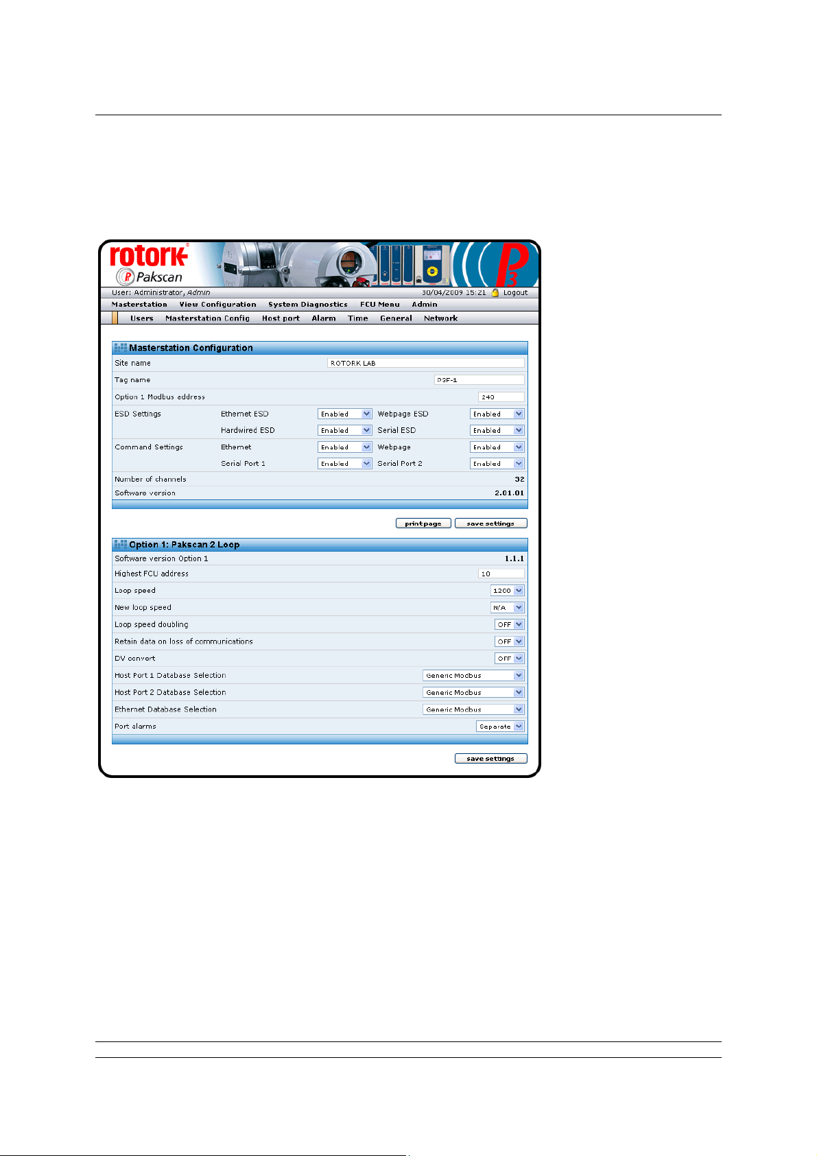
The Web Browser
Because the system and browser remembers visited pages, either the Users page will come up, or
one of the previously visited Admin level pages will appear.
Click on Masterstation Config to enter the main system configuration page.
Fig 62: Master station Set-up page
Modify this page to set up the master station parameters by using the drop-down menus on each
parameter. Most default values will be suitable for getting the system started, though consideration
should be made for every setting.
The Modbus address is also set on this page. Change the Modbus address to match the desired serial
communications and Modbus TCP address for access to the actuators o n the current loop. It should
not be left at 240.
71 of 82 Publication S703E V1.1 Issue 06/09
Page 72

P3F - Pakscan Master Station Technical Manual
5.6.2 Option Module Set-up (including host comms protocols)
The master station set-up page is also used for setting up the Pakscan 2 Current Loop Option card.
Set the loop performance parameters in accordance with the data recorded earlier. Make sure the
loop speed is compatible with the setting for the loop capacitance.
Set the highest field unit address parameter equal to the actual highest address.
Doubling can be set to ‘On’ if the loop performance is not fast enough. It has the effect of halving the
time to collect data from the field units.
DV Convert should be set to ‘On’ if position control is being used on the IQ, IQT, Skil or EH actuators
on the network.
Data Retain set to ‘Off’ clears all the field unit data if communication is lost. Some host systems want
the data to be retained, in which case set the parameter to ‘On’.
The communications protocols are also set on this page. Select the desired host proto col on e ach
serial communications port and the Ethernet ports for access to the actuators on the current loop.
Once the settings are as required, they must be downloaded to the master station CPU module. Click
on save settings and wait for the web page to refresh before moving to the next task.
5.6.3 Host Port Settings
The physical parameters relating to the serial ports that may be altered are set by accessing the Host
Port page.
Fig 62: Host Port Set-up page
72 of 82 Publication S703E V1.1 Issue 06/09
Page 73
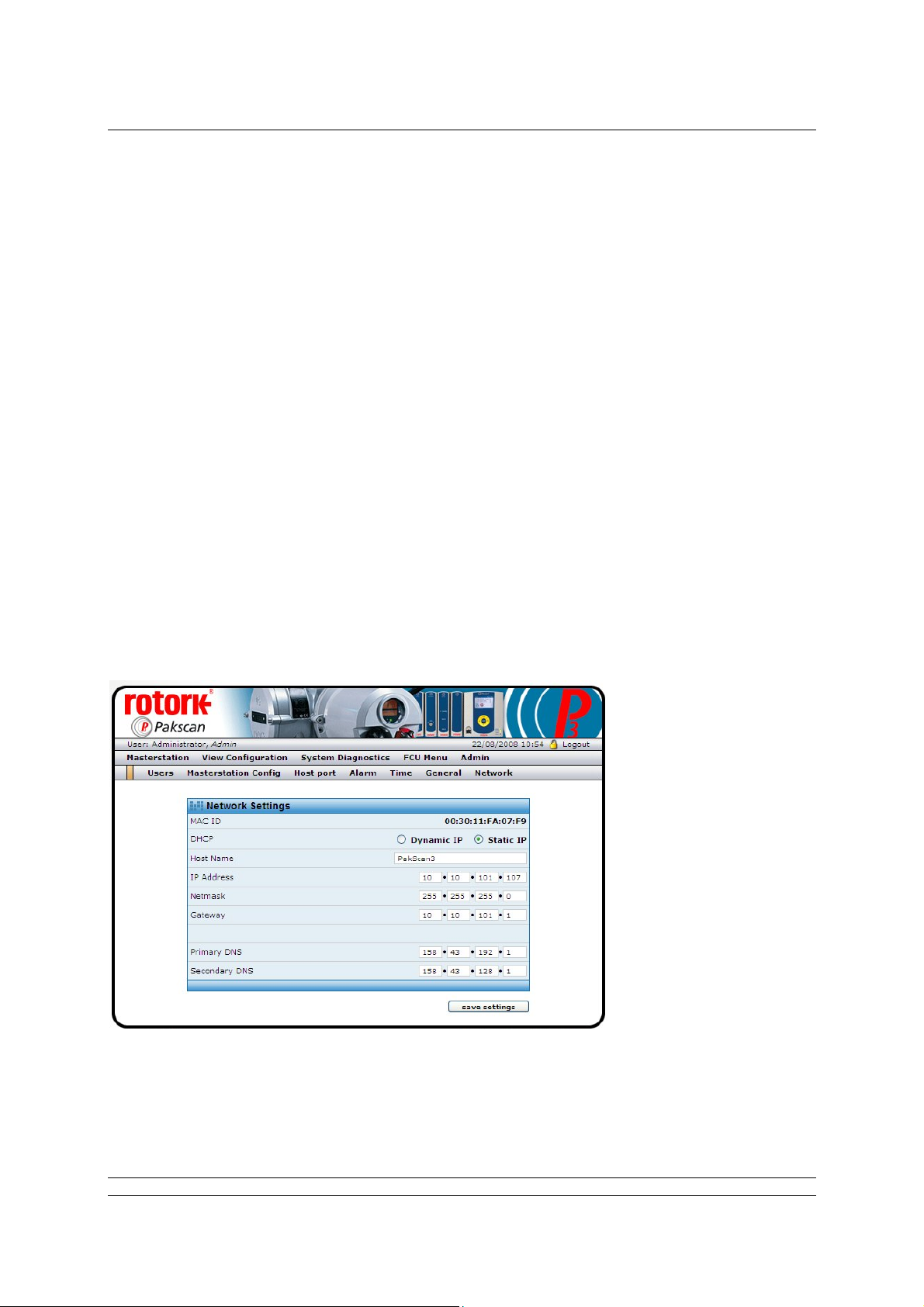
The Web Browser
The port type is determined by the DIP switch settings on the back plane pcb and the setting is
reflected in the message on the screen. The description changes to reflect the setting when the port is
set to RS232. This is particularly useful when determining the settings already in place.
For each serial port, set the Baud Rate and Parity as required. The speed may be varied bet ween
2400 and 115,200 baud, the parity may be Odd, Even, Zero or None.
The Ethernet port IP Authentication needs to be set when internet control over the web is being used.
On a private Ethernet network it is unlikely that authentication will be required.
Once the serial port settings match the system requirements for communication to the host sy stem
they must be sent to the master station CPU module. Click on save settings to send the values to the
module.
The modbus message button opens up a page where messages can be created and sent to the
master station, one at a time. The reply is shown and can be examined to ensure that the expected
performance is being obtained. Note that these messages are sent over the Ethernet link using
Modbus TCP and not over the Serial link and therefore do not test all the serial port settings.
5.6.4 Setting the IP Address
The IP address for TCP/IP and Modbus TCP communication is set on the Network page.
The MAC ID for each Pakscan P3F CPU module is different, but fixed at time of manufacture. The IP
address and Netmask can be altered to suit the individual application and match the needs of the
network.
Fig 63: Network IP Address set up page.
Once the desired values have been set, click the save settings button to download the values to the
Master Station CPU module. When the IP address is changed, the comms link will fail when the new
73 of 82 Publication S703E V1.1 Issue 06/09
Page 74

P3F - Pakscan Master Station Technical Manual
value becomes active in the master station. The web browser must be restarted and directed to the
new IP address.
Re-establishing Ethernet Communication with a new IP address:
Because most PCs associate a MAC ID to each IP address, the chances are that the PC will not
be able to re-establish communication with the master station until the PC has been rebooted
through a complete power cycle.
74 of 82 Publication S703E V1.1 Issue 06/09
Page 75

Commissioning and Control
6. MAKING THE SYSTEM WORK
ALWAYS ENSURE THE PLANT IS IN A SAFE CONDITION
AND ALL THE ACTUATOR CONTROLS ARE PLACED IN
LOCAL BEFORE COMMENCING ANY COMMISSIONING
6.1 Commissioning the System
The current loop needs to be commissioned to enable the system to locate and identify every actuator.
The master station and laptop PC can be used to perform the commissioning. At the time of
commissioning the loop all the actuators must be made available, though they may be locked in ‘hand
only’ control. All field units must have a unique network address.
The two-wire loop and all the actuators should be connected to the master station, with all the
actuators left without power,
and browse to the master station web pages on the PC, then go to the System Diagnostics page.
except for the one furthest from port A. Disconnect the wires from port B
Fig 64: System Diagnostics page.
Select Option 1 Diagnostics by clicking on the diagnostics button.
75 of 82 Publication S703E V1.1 Issue 06/09
Page 76

P3F - Pakscan Master Station Technical Manual
Fig 65: Pakscan 2 Option Card (Loop Card) Diagnostics page showing complete loop.
Reset the network (current loop) by clicking the reset network button. The status information will
change and show the configuration stages. Once complete, the actuator furthest from port A should be
shown on the Network Map.
Power on the next nearest actuator and reset the network again. This actuator should then appear on
the list. Continue to power on the actuators and reset the network working back towards port A until all
the actuators are connected and appear on the map.
Now connect the port B wires and disconnect the port A wires. Reset the network and check that all
the actuators are still on the map. Having verified the loop wiring and the connection of all the
actuators in both directions, finally connect the port A wires, reset the loop and all the actuators will be
ready for control.
Once the system is working with actuators connected and no loopbacks present, the diagnostic and
control pages can all be used.
6.2 Monitoring and Controlling the Actuators
The Web Browser includes the capability to control and monitor all the actuators on the Pakscan
current loop connected to the Option Module. Go to FCU Menu to open the page showing all the
connected actuators and their status.
76 of 82 Publication S703E V1.1 Issue 06/09
Page 77

Commissioning and Control
Fig 66: List of Connected Field Units
This screen lists the FCUs in address order, their type and current condition. The FCU Control button
will bring up the page showing the information in more detail.
Fig 67: Detailed Actuator Condition page.
77 of 82 Publication S703E V1.1 Issue 06/09
Page 78

P3F - Pakscan Master Station Technical Manual
The actuator can be moved by the Open and Close buttons and any alarms present displayed by
clicking Show Alarms. The page will automatically refresh if the valve is moved and the buttons at the
top of the page can be used to move to the next or previous actuator on the network.
Once the system is running correctly, make a note of all the settings and field unit parameters for
future reference.
The Pakscan Current Loop network and associated actuators will now be available for the host DCS
or PLC to control and monitor the plant.
78 of 82 Publication S703E V1.1 Issue 06/09
Page 79

Safety
GENERAL SAFETY INFORMATION
This is customer information regarding installation, user safety, environmental and electromagnetic
compatibility.
This information is provided to assist with conformance to the Health and Safety Act 1974 and various
directives of the European Community.
Mechanical
Care should be taken to avoid dropping heavy items - for example during installation or maintenance.
Protective footwear should be worn when appropriate. Rotork products are not intended to carry the
stresses involved in support of items supplied by others unless this has been specifically agreed to by
the company.
Care should be taken to avoid contact with sharp edges or points, particularly if the product is partially
dismantled.
Electrical
Products should be installed in accordance with BS6739.
Electrical supplies and earthing should be in accordance with BS7671
Care should be taken to ensure that voltages or currents in excess of those specified, or of reversed
polarity, are not applied to the terminals of any products. If such excess is applied, the product should
be returned to Rotork or otherwise checked by a competent person before re-use, even if no damage
is immediately evident. Use only the specified fuse type and rating as replacements.
Products should not be operated with safety protective covers removed, or with safety interlocks overridden. Some products are designed to allow access by skilled persons whil st power is applied. The
user must control such skill level and access and it should be remembered that electromagnetic
compatibility may be compromised.
Galvanically isolated input or output signal circuits are provided by certain products. A competent
person must decide upon any earthing arrangements for such circuits and users should regard them
as carrying a dangerous voltage, unless they are earthed locally.
Batteries
Batteries must not be short circuited, or disposed of by burning. They must not be opened, punctured
or crushed. Large batteries should only be used in well ventilated places. Their cases are generally
ABS plastic resin and as such should be cleaned only with a damp cloth and not exposed to organic
solvents.
Electromagnetic Compatibility
To ensure conformance to the EC Directive 89/336/EEC, installation should adopt the following cable
arrangements:
79 of 82 Publication S703E V1.1 Issue 06/09
Page 80

P3F - Pakscan Master Station Technical Manual
All digital data cables and all analogue signal cables operating at or below 50 Volts should be shielded
either by braid, armouring or metal conduit.
Such shields should be earthed as closely as possible to the product. If for the avoidance of gro und
loops it is not possible to earth these shields locally at low frequencies, they should nevertheless be so
earthed via a capacitor effective at radio frequencies.
A single shield may be shared by any number of analogue signal cables.
Functional Reliability
Reliability predictions, (including failure mode and effect analysis), are calculated by Rotork using
statistical methods and the resulting figures should only be used for statistical purposes. These
predictions are only valid if the maintenance procedures and maintenance intervals stated in Rotork
documentation are observed.
Environmental
Products should only be operated within the environment specified on the product data sheet. Take
care not to obstruct ventilation paths.
In the event of ingress of any fluid or spray, products should be immediately switched off, and cleaned
and dried by a competent person before re-use.
Chemical
Specific hazards will be the subject of product data. As a matter of good working practice, oral contact
should be avoided.
Independently Certified Products
Such products must not be modified in any way by the user, and must be applied, operated and
maintained in accordance with the relevant standards, certificates and reports.
Product Data Sheets
These should be checked for information that supplements or replaces that given above.
80 of 82 Publication S703E V1.1 Issue 06/09
Page 81

Safety
(This page is intentionally blank)
81 of 82 Publication S703E V1.1 Issue 06/09
Page 82

P3F - Pakscan Master Station Technical Manual
USA Head Office
Rotork Controls Inc
675 Mile Crossing Blvd
Rochester
New York 14624
USA
Tel: +1 585 247 2304
Fax: +1 585 247 2308
e-mail: info@rotork.com
htpp://www.rotork.com
Rotork reserves the right to amend
and change specifications without
prior notice.
Published data may be subject to
change
UK Head Office
Rotork Controls Ltd
Bath
England
BA1 3JQ
Tel: +44 (0) 1225 733 200
Fax: +44 (0) 1225 333 467
e-mail: mail@rotork.co.uk
82 of 82 Publication S703E V1.1 Issue 06/09
 Loading...