

rotork IW Series, MOW Series, MTW Series, IB Series, IS Series Installation Manual

Gearbox Installation Manual
Rotork Gears IW, MOW, MTW, IB and IS ranges
(Electronic copy available on www.rotork.com)
! This manual contains important safety information. Please ensure it is
thoroughly read and understood before installing the gearbox.
! This manual is produced to enable a competent person to install, operate,
adjust and inspect Rotork gearboxes. Only persons competent by virtue of
their training or experience should install, maintain and repair Rotork
gearboxes.
! The gearbox weight is recorded on the packaging and on a label attached to
the gearbox.
! WARNING: Gearbox may present an unbalanced load.
! WARNING: With respect to handwheel operation of Rotork gearboxes, under
no circumstances should any additional lever device such as a wheel-key or
wrench be applied to the handwheel in order to develop more force when
closing or opening the valve as this may cause damage to the valve and/or
gearbox or may cause the valve to become stuck in the seated/backseated
position.
! WARNING: Damage to protective coatings should be correctly rectified and
may invalidate warranty.
RG-INSTALL-009 / PUB027-027_0917 Page 1 of 15
Date 26/09/2017

Contents
1. Introduction ............................................................................................................................................... 3
2. Health and Safety ..................................................................................................................................... 3
3. Storage ...................................................................................................................................................... 3
4. Unpacking ................................................................................................................................................. 3
5. Handling .................................................................................................................................................... 3
6. Installation & Maintenance of Worm Combinations ............................................................................. 4
6.1. Output Sleeve Removal, Machining and Re-Fitting ..................................................................... 4
Important Notes in Figure 2: ........................................................................................................................... 4
6.2. Mounting to the Valve ..................................................................................................................... 6
6.3. Baseplate Thread Depths ................................................................................................................ 7
6.4. Setting the Gearbox Stops to Suit the Valve (IW and MOW Only) .............................................. 7
6.5. Worm Combination Maintenance ................................................................................................... 8
7. Installation & Maintenance for Multi-Turn IB & IS Combinations ........................................................ 9
7.1. Output Sleeve Removal, Machining and Re-Fitting ..................................................................... 9
7.2. Mounting to the Valve ................................................................................................................... 10
7.2.1. Gearboxes IB2 to IB13 and IS2 to IS13, IS15 and IS17. ..................................................... 11
7.2.2. Gearboxes IB14 and IS14, IS16, and IS18-IS21 ................................................................... 12
7.2.3. All IB and IS Gearboxes ........................................................................................................ 13
7.3. Maintenance Instructions for IB & IS Gear Operators................................................................. 13
8. Paint Repair Procedure .......................................................................................................................... 14
9. Reference ................................................................................................................................................ 14
10. Handwheel Types .............................................................................................................................. 15
RG-INSTALL-009 / PUB027-027_0917 Page 2 of 15
Date 26/09/2017

1. Introduction
Unless otherwise specified the gearbox is supplied assembled. In the case of quarter turn gearboxes, the
gearbox stops have been set to a nominal 90° open and close position.
! The IW gearbox stops must be re-set for the stroke of the valve after combination installation.
2. Health and Safety
Work undertaken must be carried out in accordance with the instructions in this and any other relevant
manuals. The user and those persons working on this equipment should be familiar with their responsibilities
under any statutory provisions relating to the Health and Safety of their workplace. Due consideration of
additional hazards should be taken when using the gearbox with other equipment. Should further information
and guidance relating to the safe use of the Rotork products be required, it will be provided on request.
The mechanical installation should be carried out as outlined in this manual and also in accordance with
relevant standards such as British Standard Codes of Practice. No inspection or repair should be undertaken
unless it conforms to the specific hazardous area certification requirements. For maintenance of the actuator,
refer to the actuator installation and maintenance manual.
! WARNING: The gearbox enclosure materials may include cast iron, SG iron, carbon steel or
stainless steel.
3. Storage
If your gearbox cannot be installed immediately store it in a clean dry place until you are ready to install in
situ. Recommended storage temperature range: 0°C to 40°C (32°F – 104°F).
4. Unpacking
Gearboxes are packed in a variety of configurations depending on size, type and quantity of the
consignment.
It is the responsibility of the individual unpacking and handling the combination to carry out a risk
assessment for the supplied arrangement to ensure safe working. Refer to Section 5 Handling.
Packaging material used may include wood, cardboard, polyethylene and steel. Packaging should be
recycled according to local regulations.
5. Handling
! Individual weights for gearboxes are recorded on their respective nameplates
! Only trained and experienced personnel should carry out handling. At all times, safe
handling must be ensured.
! Each combination must be assessed to identify all risks associated with handling.
! The gearboxes must be fully supported until full valve shaft/stem engagement is achieved
and the gearbox is secured to the valve flange.
! Once connected to the valve, each assembly must be assessed on an individual basis for
safe handling/lifting. Never lift the complete combination-valve assembly via the gearbox.
! If it is necessary to lift the gearbox using lifting equipment, certified soft slings are
recommended. Damage to protective coatings should be correctly rectified and may
invalidate warranty.
! We recommend fitting a bolt and washer system onto the baseplate of IB and IS gearboxes
before moving them, as demonstrated in Figure 7 and Figure 8.
RG-INSTALL-009 / PUB027-027_0917 Page 3 of 15
Date 26/09/2017
6. Installation & Maintenance of Worm Combinations
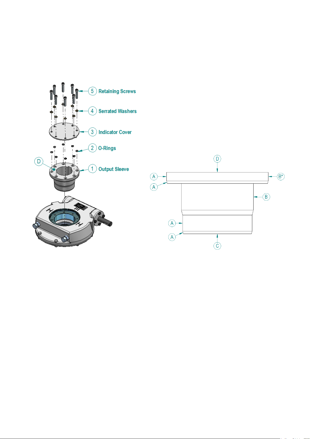
Figure 1 - IW3-11 Output Sleeve Fitting
Figure 2 - IW Output Sleeve, Important Surfaces
6.1. Output Sleeve Removal, Machining and Re-Fitting
Gearbox sizes IW12 to IW16 have an output which is directly machined as specified with the order. All other
worm gearbox combinations have a removable output sleeve. See Item 1, Figure 1.
Figure 1 shows the removal of the output sleeve from the gearbox. See Figure 2 for removing the output
sleeve without damaging the sealing faces.
Important Notes in Figure 2:
A: The surfaces marked ‘A’ are sealing or bearing faces and must not be damaged.
B: The surfaces marked ‘B’ can be used for chucking the output sleeve. *Note, this surface can
only be used for chucking on MTW gearboxes. NOT IW or MOW units.
C: To remove the output sleeve from the gearbox, a force may have to be applied to the face
marked ‘C’ of the output sleeve.
D: It is recommended to apply silicon sealant to the face marked ‘D’ when fitting the indicator
plate.
Unless specifically requested at the ordering stage, the output sleeve will be supplied blank and must be
machined to suit the valve shaft.
Referring to the item numbers in Figure 1, the output sleeve can be easily removed from the top of the
gearbox by first removing the retaining screws (5). The screws are either serrated under their heads or are
fitted with serrated washers (4). Then remove the indicator/cover plate (3).
RG-INSTALL-009 / PUB027-027_0917 Page 4 of 15
Date 26/09/2017

Figure 3 - O-Ring Inspection
It is essential to fit the two part washers
the correct way round with the cam
faces of the washers joining. Place the
O-rings over the screw threads and
against the indicator plate.
Referring to Figure 3, O-rings (6) and (7) are to be inspected for damage, greased and properly seated
before re-fitting the output sleeve. If the O-ring is damaged then it should be replaced prior to fitting the
output sleeve.
! WARNING: Removing the retaining screws will result in the loss of control of the valve.
Referring to Figure 1, O rings (2) are used to seal the indicator plate, output sleeve and retaining screws.
Upon final installation on the valve, screws (5) must be tightened to the correct torque figures as shown on
the label on the underside of the indicator/cover plate.
Before re-fitting the output sleeve after machining, check that the surfaces marked ‘A’ in Figure 2 are not
damaged. Damaged surfaces can break the gearbox seals and cause water ingress or grease leakage.
Applying a thin layer of grease to the faces marked ‘A’ will make refitting of the sleeve easier.
As detailed in Figure 1 and Figure 2, it is recommended that silicon sealant is applied to face ‘D’ to seal the
indicator/cover plate to the output sleeve. Taking care not to apply sealant to the o rings (2) or the sealing
faces with the o rings.
Before re-assembly, clean and de-grease the top face of the output sleeve, underside of the indicator/cover
plate, and the socket head cap screws. Make a note of the tightening torque required for the output sleeve
screws on the label on the underside of the indicator plate. Insert the screws and washers into the holes in
the indicator/cover plate, as per Figure 1.
RG-INSTALL-009 / PUB027-027_0917 Page 5 of 15
Date 26/09/2017
 Loading...