

Page 1

Publication PUB089-005-00_0618
Mk3 Foundation Fieldbus
Option Card
Technical Manual
Page 2

Foundation Fieldbus CP Option Card Technical Manual
2 of 116 Publication PUB089-005-00_0618
Note 1: Throughout this manual the Foundation Fieldbus may be abbreviated to FF
Note 2: Throughout this manual the FF Interface Card may simply be referred to as the FF CP card.
Note 3: The information in this manual relates to the FF CP card firmware / hardware versions:
M3.1 / T1.4 / H1.1 (or newer)
Note 4: The screen dumps used in the manual have generally be taken from a National Instruments FF
configurator tool’s screen. Other configurator tools may show the same data on a different set of
screens.
Note 5: This manual is to be used in conjunction with the relevant actuator setting manual and assumes a
pre-existing level of knowledge of using both FF and the particular actuator type. It is advised that
the relevant technical manual is read before attempting to set-up FF within the actuator.
Note 6: The FF CP card described in this manual contains static-sensitive devices. Suitable
precautions, such as wearing an earthed anti-static wrist strap, should be taken before
handling the card. It should be kept in an anti-static bag or box while it is not fitted within an
actuator.
As we are continually developing our products their design is subject to change without notice.
© The contents of this document are copyright and must not be reproduced without the written permission
of Rotork.
The name Rotork is a registered trademark.
Foundation is a registered trademark of the Fieldbus Foundation.
NI-FBUS is a registered trademark of National Instruments.
Windows is a registered trademark of The Microsoft Corporation.
The names; Allen, Bluetooth, Modbus, Rotork and Torx are registered trademarks.
Page 3

Contents
Publication PUB089-005-00_0618 3 of 116
Contents
Glossary of Terms: ......................................................................................................................... 6
Abbreviations used: ....................................................................................................................... 8
Supporting Documents: ................................................................................................................. 8
1 INTRODUCTION ................................................................................................ 9
2 FF CARD PROPERTIES ................................................................................. 11
2.1 Mechanical properties ........................................................................................................11
2.2 Electrical properties ...........................................................................................................12
2.3 Operation and storage .......................................................................................................12
3 FITTING THE FF CP CARD ............................................................................ 13
3.1 Inside a Rotork Actuator ..................................................................................................13
3.1.1 Inside an IQ3/IQT3 actuator ...............................................................................13
3.1.2 Inside an SI3 actuator .........................................................................................15
3.1.3 Inside a CVA actuator .........................................................................................16
3.1.4 Inside a CMA actuator ........................................................................................17
3.1.5 Inside a K range actuator ...................................................................................18
3.1.6 Inside a CK actuator ...........................................................................................19
3.2 Replacing or Fitting an FF CP Option Card .....................................................................20
3.3 Socket, LED and Jumper functions of the FF card .........................................................21
4 IEC 61158 DATA HIGHWAY AND CONNECTIONS ....................................... 23
4.1 Data highway ......................................................................................................................23
4.2 Fieldbus power supply .......................................................................................................24
4.3 Termination network ..........................................................................................................26
5 THE ACTUATOR INPUT AND OUTPUT SIGNALS ........................................ 27
5.1 Controls ...............................................................................................................................28
5.1.1 Controls priority ..................................................................................................31
5.1.2 Foundation control using DO blocks only ...........................................................32
5.1.3 Foundation control using the AO block only .......................................................32
5.1.4 Foundation control using both DO and AO blocks .............................................33
5.1.5 The ‘S’ contacts (RLY 1 to RLY 4) controlled by the DO blocks ........................34
5.1.6 Foundation network control disable feature .......................................................34
5.2 Discrete Input status feedback .........................................................................................35
5.2.1 Discrete Inputs ....................................................................................................36
5.2.3 Discrete Inputs reporting the FF CP card condition ...........................................40
5.3 Actuator Analogue Input feedback ...................................................................................41
Page 4

Foundation Fieldbus CP Option Card Technical Manual
4 of 116 Publication PUB089-005-00_0618
6 FUNCTION BLOCKS ...................................................................................... 43
6.1 Resource Block ..................................................................................................................44
6.2 Transducer Block ...............................................................................................................47
6.2.1 Transducer block parameters .............................................................................47
6.2.2 Changing the settings in the Transducer block. .................................................53
6.2.3 Editing the Foundation specific parameters 1-23 and 99 ...................................54
6.2.4 Editing the actuator setup parameters 50-67 .....................................................54
6.2.5 Editing the control parameters 65 - 66 ...............................................................59
6.3 Analogue Input blocks .......................................................................................................60
6.4 Discrete Input blocks .........................................................................................................61
6.5 Analogue Output block ......................................................................................................63
6.6 Discrete Output blocks ......................................................................................................65
6.6.1 Multiple block – single bit control ........................................................................66
6.6.2 Single block – multiple bit control. ......................................................................66
6.7 PID Control block ...............................................................................................................68
6.8 Control Selector block .......................................................................................................69
7 LINK ACTIVE SCHEDULER (LAS) ................................................................. 71
7.1 Creating a schedule ...........................................................................................................74
7.2 Connecting the blocks .......................................................................................................75
7.3 Downloading the schedule ................................................................................................75
7.4 Optimising the downloaded schedule ..............................................................................76
8. SETTING UP THE FF CP CARD (QUICK START GUIDE) ............................. 77
8.1 Setting up with the Setting Tool .......................................................................................78
8.2 Insight 2 ...............................................................................................................................79
8.3 Methods ...............................................................................................................................81
8.4 Control output function block settings ............................................................................82
8.4.1 Analogue Only control ........................................................................................83
8.4.2 Discrete Only control ..........................................................................................83
8.4.3 Mixed Analogue and Discrete control .................................................................84
8.4.4 Hard-wired inputs - Aux Input Function ..............................................................84
8.5 Status feedback function block settings .........................................................................85
8.5.1 Analogue position and torque data .....................................................................85
8.5.2 Discrete Input data .............................................................................................85
8.6 Default settings ...................................................................................................................86
8.7 Using the DTM (with FDT) ..................................................................................................87
9 THE FF CP CARD FIRMWARE AND DD FILES ............................................. 89
9.1 Firmware ..............................................................................................................................89
9.2 Device Description Files ....................................................................................................89
Page 5

Contents
Publication PUB089-005-00_0618 5 of 116
APPENDIX A – HANDLING FAULT CONDITIONS. ................................................ 91
APPENDIX B – FUNCTION BLOCK MODE – LO ................................................... 92
APPENDIX C – PID APPLICATION. ....................................................................... 93
APPENDIX D – ITK6 FF SPECIFICATION DATASHEET ....................................... 96
D.1 Basic Fieldbus Function Blocks .......................................................................................96
D.2 Channel Allocation .............................................................................................................96
D.3 Segment Information ..........................................................................................................97
APPENDIX E – NAMUR NE 107 - GUIDELINES FOR SETTING UP ...................... 98
E.1 Background info: ................................................................................................................98
E.2 Test set up for FD_...._ACTIVE: ......................................................................................101
E.3 Test set up for FD_...._ALM: ............................................................................................104
APPENDIX F – CHANGING THE ITK REVISION .................................................. 106
APPENDIX G – DTM .............................................................................................. 110
APPENDIX H – HOST INTEROPERABILITY SUPPORT TEST (HIST) ................ 113
APPENDIX I – COMMON PROBLEMS ................................................................. 114
Page 6

Foundation Fieldbus CP Option Card Technical Manual
6 of 116 Publication PUB089-005-00_0618
Glossary of Terms:
Automatic (AUTO) A possible mode of a function block which means the block runs its
algorithms, producing data at its inputs or outputs.
Basic Device A basic device is any device not having the capability to control
communications on an H1 fieldbus segment.
Back calculation output This parameter is available on output function blocks, and provides a
(BKCAL_OUT) feedback mechanism to control blocks such as PID.
Capabilities File A file describing the communication objects in a fieldbus device. A
configuration device can use Device Description (DD) Files and
Capabilities Files to configure a fieldbus system without having the
fieldbus devices online.
Cascade (CAS) A possible mode of a function block which refers to an input derived
from the output of another function block.
Device Description (DD) A machine-readable description of all the blocks and block parameters
of a device.
Fieldbus The digital, two-way, multi-drop communication links.
Fieldbus Interface Card (FIC) The option card fitted to the actuator which provides the
communications interface between the DCS and the actuator.
Function Block (FB) Also known as standard function block. This is a named block
consisting of one or more inputs and outputs. These are built into
fieldbus devices to achieve the desired control functionality. The FF
CP has Analogue Input (AI), Analogue Output (AO), Digital Input (DI),
Digital Output (DO), Control Selector (CS) and PID control (PID).
H1 A term used to describe a FF highway operating at 31.25 kbit/sec.
Initialization Manual (IMAN) The forward path to a physical output is broken and the output is
tracking the downstream block. This will result in the control action
being suspended.
Interoperability The capability for a device from one manufacturer to interact with that
of another manufacturer, on a fieldbus network, without loss of
functionality.
Input / Output Options This parameter is contained within output function blocks and
(IO_OPTS) allows different parameters to appear at various connection points.
Link Active Scheduler (LAS) One Link Master (LM) device functions as the fieldbus LAS at any one
time. The LAS is the Fieldbus device that is currently controlling
access to the Fieldbus. A device that is responsible for keeping a link
operational. The LAS executes the link schedule, circulates tokens,
distributes time, and probes for new devices.
Page 7

Contents
Publication PUB089-005-00_0618 7 of 116
Local Override (LO) A possible mode of a function block where the block can only be
monitored, and no changes can occur to its set points.
Manual (MAN) A possible mode of a function block where the final element is
manually input by a user, as opposed to being controlled by its
algorithms.
Out Of Service (OOS) A possible mode of a function block which means the block does not
run its internal algorithms and cannot be used.
Process Variable (PV) A process variable is a condition of the process fluid (a liquid or gas)
that can change the manufacturing process in some way. Common
process variables include pressure, temperature, flow rate, etc.
Readback This is the parameter in an output function block which indicates the
actual feedback of a process, as opposed to the desired value.
Remote Cascade (RCAS) A possible mode of a function block which refers to an input derived
from non-function block outputs.
Resource Block (RB) A block that describes the characteristics of the fieldbus device such
as; the device name, manufacturer and serial number.
Schedules Communication events that occur at the same time during each
control cycle. The schedule defines when Function Blocks (FBs)
execute and when data / status information is published on the bus.
Segment A Foundation Fieldbus network is made up of devices connected by a
serial bus. This serial bus is called a segment (also known as a link).
A section of an H1 fieldbus that is terminated in its characteristic
impedance. Segments can be linked by Repeaters to form a longer
H1 fieldbus. Each Segment can include up to 32 H1 devices.
Transducer Block (TB) A block that is an interface to the physical, sensing hardware in the
device. It also performs the digitising, filtering, and scaling
conversions needed to present input data to function blocks, and
converts output data from function blocks. The block decouples the
Function Blocks from the local input/output (I/O) functions required to
read the limit switches and command the actuator to move.
Virtual Communication Preconfigured or negotiated connections between virtual field devices
Relationship (VCR). on a network. The quantity of VCRs able to be handled by an H1
gateway, or Link Master usually determines the number of devices on
an FF highway.
Virtual Field Device (VFD) The virtual field device is a model for remotely viewing data described
in the object dictionary. The services provided by the Fieldbus
Messaging Specification allow you to read and write information about
the object dictionary, read and write the data variables described in
the object dictionary, and perform other activities such as uploading or
downloading data and invoking programs inside a device.
Page 8

Foundation Fieldbus CP Option Card Technical Manual
8 of 116 Publication PUB089-005-00_0618
Abbreviations used:
AI Analogue Input (Blocks AI1, AI2)
AO Analogue Output (Block A0)
BTST Bluetooth Setting Tool
CFF Common File Format
Comms Communications
CP Common Protocol
CS Control Selector Block
DCS Distributed Control System
DD Device Description
DI Digital Input (Blocks DI1, DI2, DI3, DI4, DI5)
DO Digital Output (Blocks DO1, DO2, DO3, DO4)
DSM (Actuator) Digital Switch Mechanism
DTM Device Type Manager
ESD Emergency Shut Down
FB Function Block
FDT Field Device Tool
FF Foundation Fieldbus
FIC Fieldbus Interface Circuit
HIST Host Interoperability Support Test
ITK Interoperability Test Kit
LAS Link Active Scheduler
LM Link Master
MSM (Actuator) Mechanical Switch Mechanism
NIC Network Interface Circuit
PCS Process Control System
PDA Personal Digital Assistant
PID Proportional, Integral, Derivative; A type of function block which refers to a closed
loop control algorithm
PST Partial Stroke Test
RAM Random Access Memory
RB Resource Block
ROM Read Only Memory
SW Software
TB Transducer Block
VCR Virtual Communication Relationship
Supporting Documents:
Available from the Fieldbus Foundation, Austin, Texas
Technical Overview of Foundation Fieldbus FD-003 (all parts).
Wiring and Installation 31.25 kbit/s, AG-140
Page 9
Introduction
Publication PUB089-005-00_0618 9 of 116
1 INTRODUCTION
This manual is designed to be an aid to commissioning and will assist with achieving a
successful integration of Rotork’s FF product into a DCS’s FF network. Correct installation
should ensure a lifetime of trouble free use. This is not a manual on how to use FF. Due to the
complex nature of the protocol, Rotork strongly recommends users attain a sufficient level of
FF competency prior to attempting any FF commissioning work.
The FF CP option card is the third evolutionary step in Rotork’s Foundation Fieldbus journey. It has
been certified as conforming to the open fieldbus standard IEC 61158 and is suitable for use on an FF
H1 highway. The H1 highway uses two copper wires to both to carry the digital messages and to
supply power to all the devices connected on the highway. As such it is necessary to have a suitable
power supply and termination filter on the highway for the FF nodes to function.
The current version of the FF card may be fitted into any of the current Rotork Controls’ actuator
product range. The FF card is an integral part of the actuator in which it is housed and is fitted within
the main electrical housing. This electrical housing need never be opened once the actuator leaves
the assembly plant. All adjustments to the settings for the FF card may be made via the Foundation
data highway using a suitable network configuration tool. There is no external marking on the actuator
to show the FF card serial number since the whole module may be replaced if it should fail.
The FF card’s circuits do not impinge on the actuator control electronics; the actuator itself remains
fully self-protecting. The card performs the tasks of IEC 61158 interface, actuator data collection and
the issuing of actuator commands.
The FF CP card may command the actuator into which it is fitted to open, stop, close, perform an ESD
operation, perform a partial stoke operation or move to a set position. Commands to the module come
from the network and may be generated in another actuator or device on the network using peer to
peer, publisher/subscriber communication. Additionally, digital and analogue status information
relating to the actuator is published for the other devices to read.
For a quick start guide see section 8.
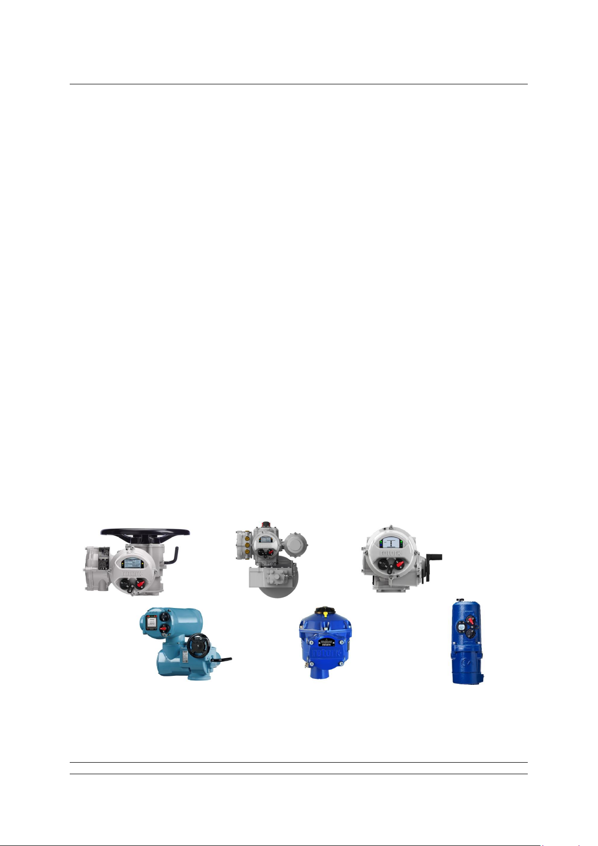
Fig 1.1: Some of the actuators which use the FF CP card
Page 10

Foundation Fieldbus CP Option Card Technical Manual
10 of 116 Publication PUB089-005-00_0618
1.1 General
The FF CP card is capable of performing the following functions:–
a) Link Master / Link Active Scheduler
b) Basic Device
The in-built function blocks vary in availability between the different actuator types. The input and
output blocks are used to link to the transducer block and tie to the available actuator functions. For
example the AI block associated with actuator torque measurement is only available in the DSM
actuator type. The following table lists the function blocks and their related availability in each actuator
type.
Function Block Type
Resource Block – System information
Transducer Block – Device configuration
Digital Inputs
DI 1 Closed limit or multistate
DI 2 Open limit or multistate
DI 3 Selector in remote or multistate
DI 4 General alarm or multistate
DI 5 Actuator moving or multistate
Digital Outputs
DO 1 Open or multistate
DO 2 Close or multistate
DO 3 Stop or multistate
DO 4 Single bit selectable or multistate
Analogue Inputs
AI 1 Analogue position feedback
AI 2 Torque / Thrust
Analogue Output
AO Desired position (set point command)
Controllers
PID (3 term controller)
Control Selector
Page 11
FF CP Card Properties
Publication PUB089-005-00_0618 11 of 116
2 FF CARD PROPERTIES
2.1 Mechanical properties
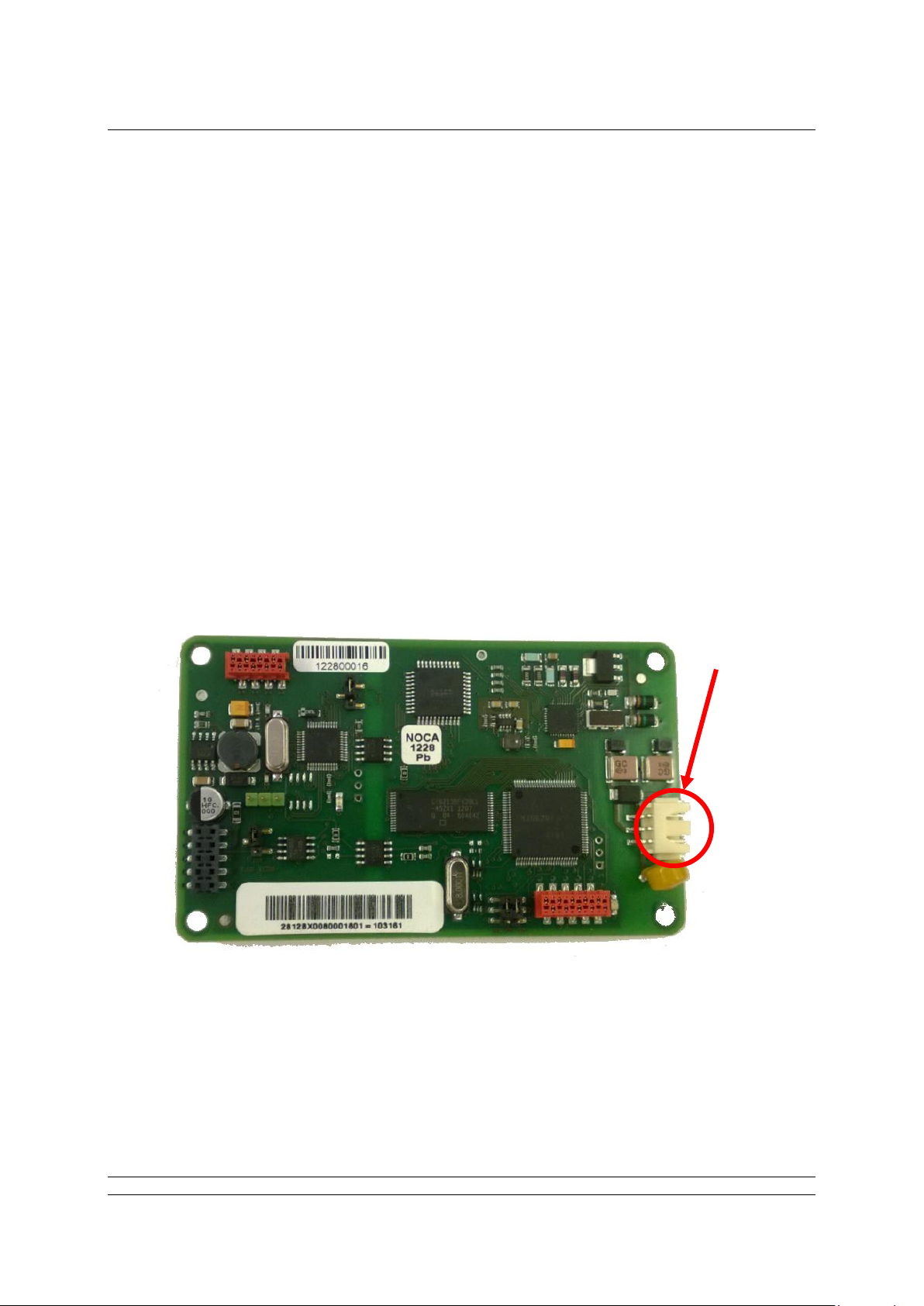
The FF CP card consists of a single network interface card that fits directly to the main actuator control
PCB. It consists of two isolated parts, the actuator interface and the network interface
Network Interface
This carries the FF highway connections and the processor handling the data highway
communication and function blocks. The Network Interface contains the FF connector (SK3),
polarised to prevent incorrect insertion. This connects to the three wire loom routed to the
terminal compartment of the actuator. Power for the Network Interface is taken from the FF
highway.
Actuator Interface
The primary connection to the actuator circuits is by a multi-pin connector on the base of
Interface Card. The PCB design ensures it may only be fitted in the correct polarisation. The
Actuator Interface on the FF CP card is powered from within the actuator.
Network Connector
Fig 2.1: The FF card, showing the network connector
Page 12

Foundation Fieldbus CP Option Card Technical Manual
12 of 116 Publication PUB089-005-00_0618
2.2 Electrical properties
The FF CP card does not sit in the main control path for the actuator and does not affect the actuator
control integrity.
Internally stored programs control the processors on the module. The Network Interface processor
software may be updated by connecting a suitable test cable and loading the new code directly, but
this cannot be done in the field The FF system allows all settings for the data highway and module
communication functions to be held in non-volatile memory on the Network Interface Card.
The FF data highway connection is fully isolated from the actuator electronics.
2.3 Operation and storage
The Module is designed to be stored in the actuator and operated within the same environment as the
actuator.
The constraints are:
Operating temperature: -40
o
C to +70oC
Storage temperature: -50
o
C to +85o C
Relative Humidity: 5% to 95% (<50
o
C) non-condensing
Refer to actuator manuals for range applicable for the particular actuator type.
Page 13
Fitting the FF CP card
Publication PUB089-005-00_0618 13 of 116
3 FITTING THE FF CP CARD
3.1 Inside a Rotork Actuator
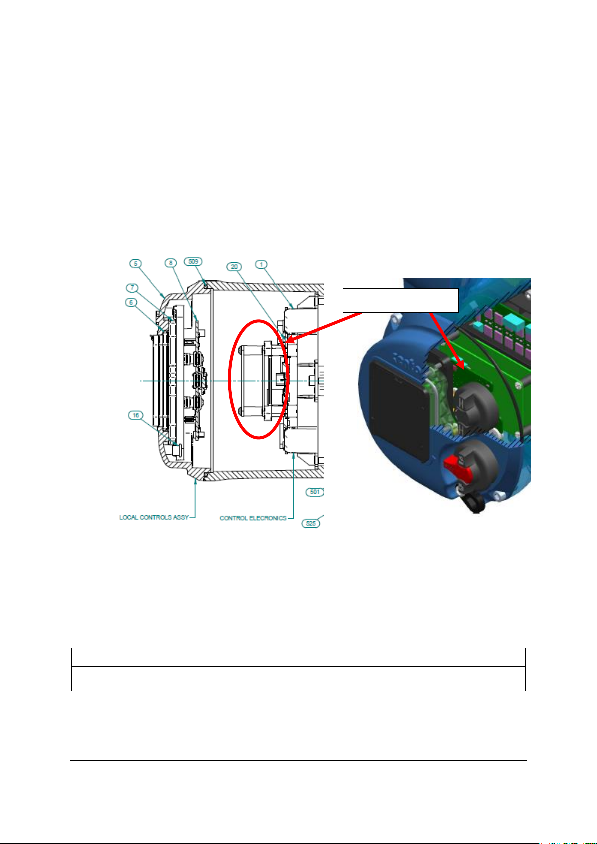
3.1.1 Inside an IQ3/IQT3 actuator
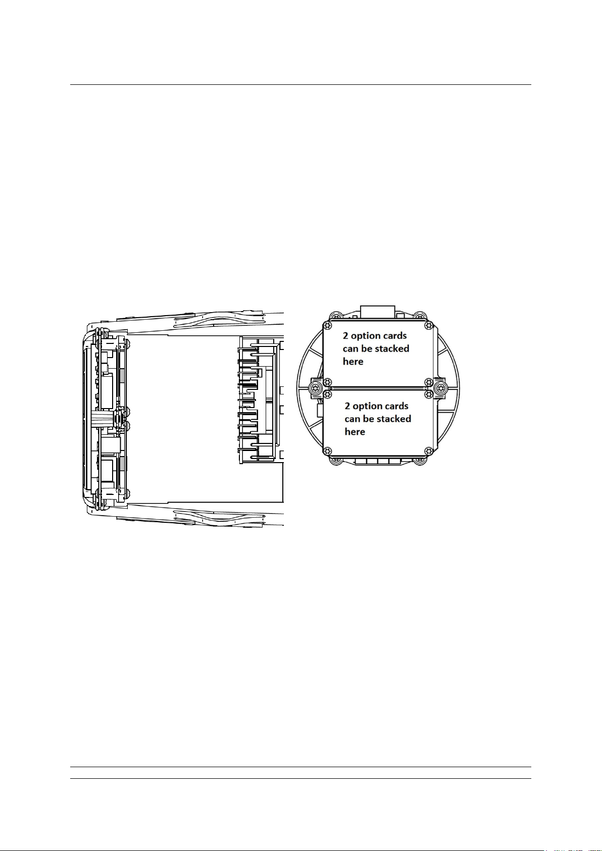
The FF CP card is suitable for fitting into IQ3 actuators. When factory-fitted, their wiring diagrams will
contain an ‘F’, e.g. 100F2000. The FF CP can be located in one of 2 or 4 option ‘slots’ located on the
back of the control module PCB, housed in the electrical cover. There are 2 slots for directly
connecting the option module to the control module and where those slots are already filled, the option
card can be fitted on top of the existing modules. The modules can be stacked 2 high where a ‘deep’
electrical cover is fitted.
Back of the control module
Fig 3.1: The FF CP card’s location behind the control module in an IQ3
With the IQ3 actuators, the remote inputs are always present (they are conditioned by the control
board) and there is an option to include Digital Outputs from relay contacts. If the FF CP is required to
operate the 4 digital outputs that can be controlled from the card, then an Extra Relay Indication card
associated with these outputs must be fitted into another option slot in the actuator.
The FF CP is connected to the control module by a 10 way header (SK2). The wiring harness from the
actuator terminal bung connects the FF H1 highway field connections to SK3.
Option Slots
Page 14

Foundation Fieldbus CP Option Card Technical Manual
14 of 116 Publication PUB089-005-00_0618
Replacing or Fitting an FF CP Option Card
The FF CP card should be replaced or fitted only in a suitable environment. The actuator must be
made electrically safe before opening any covers. The electrical housing cover should be removed
after unscrewing the four 6mm Allen machine screws. Unplug the electrical housing loom from the
control board and remove the cover. Unplug the grey ribbon cable from the edge of the control board
and unplug the black plastic carrier frame from the frame legs. Unplug the loom from the FF card.
Unscrew the Torx 20 screws holding the FF card into the frame and carefully unplug the FF card from
the control board. The replacement board is fitted in the reverse order to removal. The wiring harness
connectors are polarised so that only the correct one will fit its mating part on the circuit boards. Don’t
forget to re-connect the grey ribbon cable to the edge of the control board.
If the operation is to fit an FF CP card for the first time, then the necessary wiring loom must be added
to the internal wiring harness of the actuator. The actuator wiring diagram shows the connectors and
harness used. The wiring harness is fitted inside the actuator before attempting to fit the FF CP. This
requires that you remove the terminal bung, which is held in place by a large circlip. Be careful to
attach the wiring loom to the correct terminals, which are numbered. Re-fit the terminal bung.
Once the loom is in place, connect it to the FF CP, then fit the FF CP to the actuator main board
connector. Attach the FF CP to the frame, using the Torx 20 screws.
Once the module is fitted, the actuator should be re-assembled.
Once power is applied, the field unit parameters should be checked and corrected, where necessary.
Some FF TB parameters can be set and adjusted either by using the Infra-red and Bluetooth setting
tools or by Insight 2 using Bluetooth. The parameter setting procedure is covered by the IQ3 Full
configuration, status and monitoring user manual, PUB002-040-00, available on the Rotork web site,
www.rotork.com
Page 15
Fitting the FF CP card
Publication PUB089-005-00_0618 15 of 116
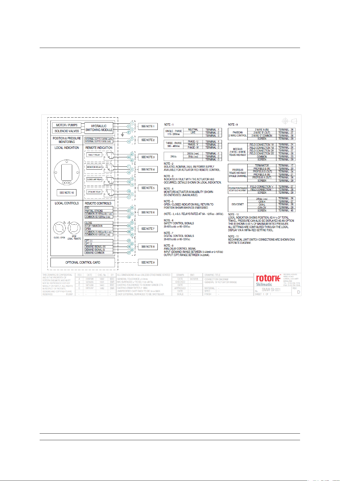
3.1.2 Inside an SI3 actuator
The FF CP is suitable for fitting into SI3 actuators. When factory-fitted, the network connections will be
as in the diagram below:
Fig 3.2: The SI3 highway interface connection table
The internal layout of the actuator will be similar to that of the IQ3, when considering installation of the
FF CP, as above.
Page 16

Foundation Fieldbus CP Option Card Technical Manual
16 of 116 Publication PUB089-005-00_0618
3.1.3 Inside a CVA actuator
The FF CP is suitable for fitting into CVA actuators. When factory-fitted, the wiring diagram will be
CXX-80 (where X can be any value). This details the option card connections to the terminal bung.
The FF CP module is fitted in the only option board slot inside the CVA electrical housing - on the
underside of the Main PCB assembly. The FF CP should be replaced or fitted only in a suitable
environment.
Fig 3.3: The FF CP located on the underside of the control PCB in a CVA actuator
To fit an FF CP card, begin by removing power from the actuator and wait until the LED on the
selector knob stops illuminating. This may take several minutes if a reserve power pack of capacitors
is fitted.
Remove the six M10 machine screws from the upper cover and lift it off carefully, while removing its
ribbon cable connector from the socket on the Main PCB.
Remove the various wiring looms from the sockets on the edges of the Main PCB, noting carefully
where they attach. Each connector is different to avoid error.
Remove the Main PCB in its plastic chassis by gently pushing the chassis legs inwards to release
them from a groove in the actuator housing.
Fit the FF CP to the underside of the Main PCB using the hardware supplied with the FF CP card.
The wiring loom from the actuator terminal bung connects the FF H1 field connections to SK3. If a new
card is being fitted as an upgrade, then the actuator will need to have the loom fitted. Remove the
terminal bung by removing the circlip and gently pulling the bung. Attach the loom and replace the
bung.
The FF CP is connected to the control module by a header, SK2.
The FF CP in the CVA must be enabled. This would usually be done during factory test, but may be
required to be completed on site for conversions to FFs or if a replacement card is fitted. To enable
the card, the Rotork PDA software Enlight (downloadable from the Rotork web site) is required to be
used to change parameter 34. It must be read and then have 2048 decimal added to it.
This procedure is best performed by a Rotork Engineer.
Page 17

Fitting the FF CP card
Publication PUB089-005-00_0618 17 of 116
3.1.4 Inside a CMA actuator
The FF CP is suitable for fitting into CMA actuators, wiring diagrams MXX-FX (where X can be any
value) detail the option card connections on the terminal strip. The FF CP module is fitted in the only
option board slot inside the CMA electrical housing.
Fig 3.4: The FF CP located in a CMA actuator
The FF CP should be replaced or fitted only in a suitable environment. The actuator must be made
electrically safe before opening any covers. The electrical housing cover should be removed after
unscrewing the four 6mm Allen machine screws.
The FF CP should be fitted in the position shown in the illustrations above. It plugs into the control
board at the 10-way header, which is SK2 on the FF CP board. There is a wiring loom which brings
the FF H1 network connection to SK3 on the FF CP.
Connection details are shown in the illustrations on the next page.
The CMA actuator will need configuring, so that it is aware that control from the field is through the FF
CP card. This is done by accessing the menu structure as shown in the CMA Installation and
Maintenance manual, PUB094-003, found on the Rotork web site.
Option location
Page 18

Foundation Fieldbus CP Option Card Technical Manual
18 of 116 Publication PUB089-005-00_0618
3.1.5 Inside a K range actuator
The FF CP is suitable for fitting into K-Range actuators; wiring diagrams similar to 1612ZFD detail the
option card connections. The FF CP module is fitted in the only option board slot inside the K-Range
electrical housing.
SK2 on the FF CP card plugs directly onto SK9 on the Main card, while a terminal bung loom brings
the FF highway signals to SK3.
FF Option Card
Main Card
Fig 3.5: The FF card located in a K-Range actuator
The FF card should be replaced or fitted only in a suitable environment. The actuator must be made
electrically safe before opening any covers. The electrical housing cover should be removed after
unscrewing the four 8mm Allen machine screws.
The FF card is attached to the main card by three plastic pillars, with one metal pillar, Torx 20 screw
and a fibre washer; as shown in the illustration above.
If an actuator is having the FF fitted for the first time, then the terminal bung loom must also be fitted.
The terminal numbers will be found in the appropriate wiring diagram, which should be included in the
fitting kit.
Page 19
Fitting the FF CP card
Publication PUB089-005-00_0618 19 of 116
3.1.6 Inside a CK actuator
The FF CP card is suitable for fitting into CKC / CKRC actuators with Px5xxxxx and Kx5xxxxx series
wiring diagrams. The connections and fitting in a CKRC are the same as the CKC so the following
information effectively relates to both actuator types. The FF CP card is normally located in the first
option board slot inside the electrical housing, using Main PCB connection SK2.
The Interface card must be correctly profiled and loaded with the appropriate connectors to match the
actuator. The illustration below shows the location of the cards in the Centronik unit.
Within the actuator the remote inputs are always present (they are conditioned by the FF CP card) and
there is an option to include Digital Outputs from relay contacts. If the FF CP card is required to
operate the 4 digital outputs that can be controlled from the card, then the Extra Relay Indication card
associated with these outputs must be fitted into the actuator. The following table describes the wiring
harnesses and their function in the Centork actuator.
FF card Socket
Wiring Harness
SK2
Power and CANbus from actuator.
SK3
FF H1 highway connection.
Fig 3.6: The FF CP card located in a Centronik unit.
Option Card Location
Page 20

Foundation Fieldbus CP Option Card Technical Manual
20 of 116 Publication PUB089-005-00_0618
3.2 Replacing or Fitting an FF CP Option Card
The FF card should be replaced or fitted only in a suitable environment. The actuator must be made
electrically safe before opening any covers.
Warning: Removal of certain covers will void warranty, it is advised that a Rotork approved
engineer perform this function.
Suitable anti-static precautions should be taken, as the actuator circuitry contains static-sensitive
components.
If an upgrade kit has been purchased please carefully follow the instructions given in the
documentation provided. It will also be necessary to have the relevant actuator maintenance manual
to hand when adding a new card.
The electrical housing cover should be removed and the existing FF card carefully unplugged from its
main connector. The Interface card will be attached to the Main PCB mounting ring by four screws,
which are T20 (or T15 if two cards are present). Once removed from the main connector the wiring
loom connectors should be removed. The replacement board is fitted in the reverse order to removal.
The wiring harnesses are polarised so that only the correct one will fit its mating part on the circuit
board.
If the operation is to fit an FF card for the first time then the necessary wiring looms must be added to
the internal wiring harness of the actuator. The actuator wiring diagram shows the connectors and
harnesses used. The wiring harnesses are fitted inside the actuator before attempting to fit the FF
card. Once the looms are in place connect them to the FF card, then fit the card to the actuator control
board/main board connector.
Once the module is fitted the actuator should be re-assembled. If an option card is fitted into an
actuator after it has left the factory then the actuator needs to be set-up to use this card in the
software, the card will not do anything until this has been done. This can be done using the local HMI
or Insight but ideally needs to be done by a Rotork service engineer. This is not necessary if a card is
being replaced with the same type of card, e.g. replacing an FF with a new FF card.
It is advisable to check the software version numbers are the same between the new and old card to
ensure consistent operation. It is also advisable to check the ITK revision of the old FF card as it may
be necessary to modify the new FF card’s ITK revision. If this needs to be done, see Appendix F.
Page 21
Fitting the FF CP card
Publication PUB089-005-00_0618 21 of 116
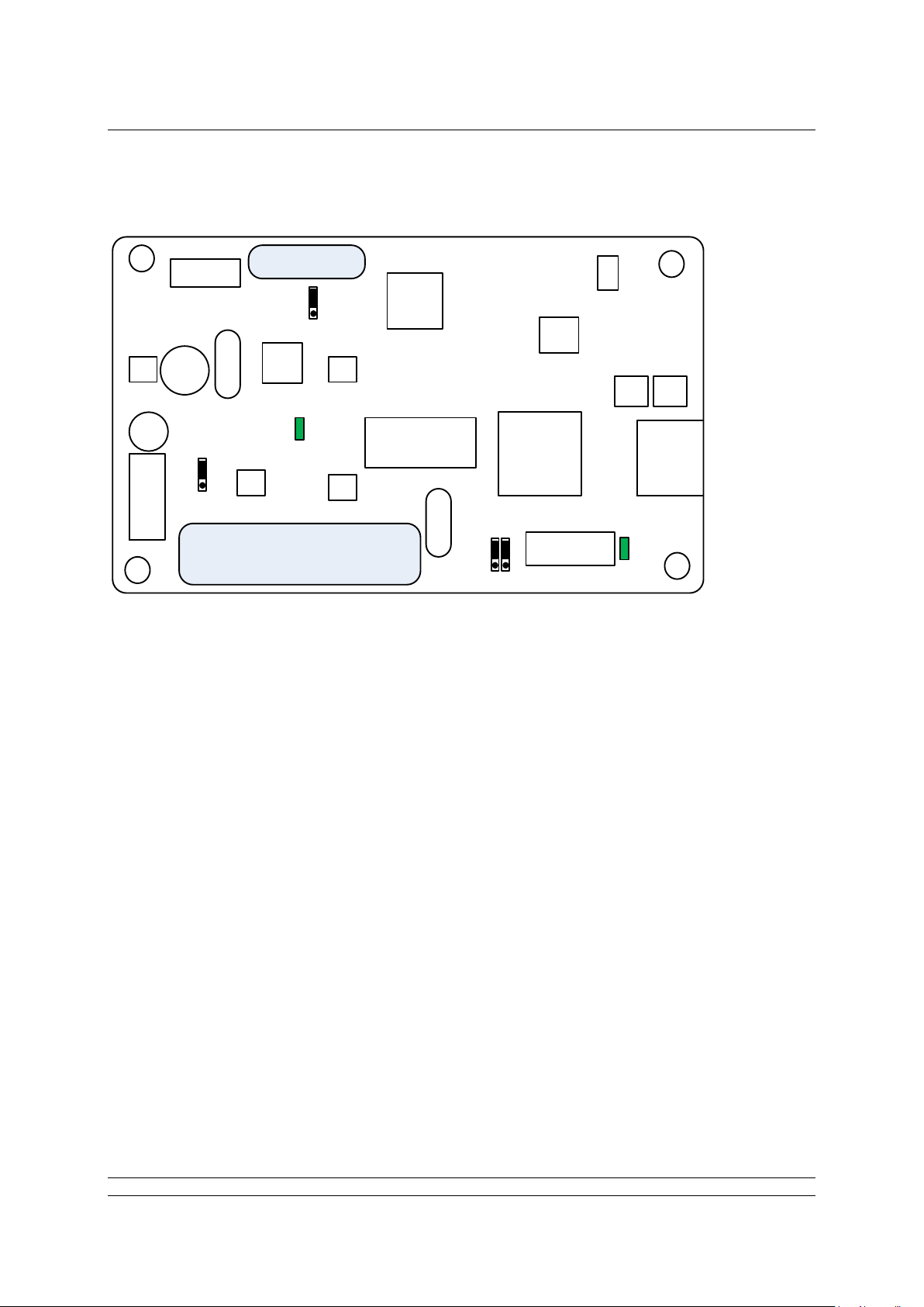
3.3 Socket, LED and Jumper functions of the FF card
Bar code
Bar code
LED 2
LED 1
JP2
SK 3
JP1
JP3
JP4
SK 1
The FF CP card includes two connectors (SK1 and SK3), two LED indicators (LED1 and 2) and four
jumpers, (JP1 – 4). The position of these jumpers should not normally require alteration from the
factory default positions. The illustration shows the default positions. The LEDs can be used to help
with system diagnostics in some cases.
The function of each connector, LED and jumper is as follows:
SK1 This socket connects the FF CP card to the actuator’s control PCB via a CANbus
highway
SK3 This socket connects the FF CP card to the FF highways via the actuator’s
terminal bung connections.
Note there are two other connectors which are used to program the FF CP card and which are
not described in this document
LED 1 Indicates the FF CP Card is communicating with the actuator’s control PCB.
LED 2 When flashing, this Indicates there is an active connection to the fieldbus highway.
When on (i.e. not flashing), this indicates the fieldbus highway power is present.
Fig 3.7: Network Interface Card - Jumper and LED functions.
Page 22

Foundation Fieldbus CP Option Card Technical Manual
22 of 116 Publication PUB089-005-00_0618
JP1, Simulation In simulation mode, the user is permitted to write to primary input/output
Mode Jumper actuator variables through the status and value attributes normally written to
by the transducer block. With JP1 ‘On’ a function block may have its simulation
‘active’ parameter enabled. When JP1 is ‘Off’ the primary actuator variables are
not write enabled. The normal position is ‘Off’, as shown on the schematic above.
See the appendix section for more information on simulation mode operation.
JP2, Hard-Write A setting can be made in the ‘FEATURE_SEL’ parameter of the Resource block
Lock which prevents the writing/changing of all configuration parameters in the FF CP
card. If the FEATURE_SEL is set to ‘Hard W Lock’, the jumper function becomes
write protect ‘On’ and ‘Off’. (See section 6.1 Resource Block). The normal position
is ‘Off’ as shown above.
JP3, CANbus This must be left in the “Off” position as shown in the fig 9 above
Terminator
JP4, Slot 0 / 1 In fig 3.7, this is shown in the slot 0 position. The jumper is moved to the slot 1
Selector position when two FF CP cards are fitted into the same actuator and one of them
already has slot 0 selected.
Fig 3.8: Simulate has been activated in the AI function block.
Page 23

IEC 61158 Data Highway
Publication PUB089-005-00_0618 23 of 116
4 IEC 61158 DATA HIGHWAY AND CONNECTIONS
4.1 Data highway
The Foundation Fieldbus network is based on the IEC 61158 data highway using copper conductors.
The network also carries the power used to supply each node on the network. In the case of the FF
card, the FF interface is powered from the fieldbus network. Only two wires are used for the data
highway and these carry both the data signal and the module power. The actuator interface card is
powered from the actuator itself and the card can only report actuator data when both the FF highway
and actuator are powered up.
The data highway must be terminated with proper balancing devices at either end. The highway can
use spur or stub connections to the devices but it is recommended to keep any stub lengths to a
minimum for successful operation. The length of the highway and number of devices connected will
vary from project to project. The standard permits up to 32 devices before a repeater in the highway
must be used, however it’s extremely unlikely that this many devices will be connected to a highway.
Similarly, the standard calls for a maximum segment length of 1900 metres before a repeater must be
used. On a 1900 metre highway, the stipulated maximum length for a stub with one actuator is 120
metres. The data highway cable type is given by the Foundation as ‘type A’. A typical example of this
type of cable is Belden 3076F.
Cable Specification
Type A Cable (e.g. Belden 3076F)
Type
2 cores, twisted pair plus overall screen
Shielding
Minimum 90% copper shielding, braid or foil
Size
18 AWG (0.8 mm2)
Resistance
24 Ohms/km max
Nominal Capacitance
80 pF/m
Fig 4.1: Typical Foundation Data Highway
Trunk
(Main highway segment)
Spurs
T
Power
supply
H1 Gateway
Field Junction Box
(including terminator)
Fieldbus power supply
(including terminator)
T
JB
JB
Page 24

Foundation Fieldbus CP Option Card Technical Manual
24 of 116 Publication PUB089-005-00_0618
4.2 Fieldbus power supply
The FF card takes power from the H1 data highway. This means the internal function blocks are
available for control connection between devices even when the actuator has no power.
The power is taken from a special DC power supply connected onto the network through a suitable
filter. The power consumption of each FF node on the network is 20 mA and the absolute minimum
voltage at the actuator terminals is 9 volts. The power supply has to contain an inductive network to
prevent attenuation of the fieldbus signal by the low impedance of the power supply itself. The
inductive network in the power pack makes sure that its equivalent impedance is quite high at the
31.25 kbits/sec frequency whilst still allowing a DC current to be drawn for the line-powered devices.
Since each node on the fieldbus consumes power from the DC supply, great care must be taken in the
design of the installation. The design must ensure that the volt drop from the power pack to the
actuator still leaves at least 9V (absolute minimum) for the FF card and ideally at least 10 Volts. The
actuators can withstand a maximum voltage of 32V from the power pack and since the current
consumption is virtually constant, a simple Ohm’s law calculation can be used to determine the
potential at each point in the network. On power up there is no additional inrush current, i.e. the inrush
current value is the same as the nominal.
The Foundation fieldbus wiring guide (AG -140) provides examples of how to calculate the voltage at
each point.
Fig 4.2: Calculating the Voltage Drop
Page 25
IEC 61158 Data Highway
Publication PUB089-005-00_0618 25 of 116
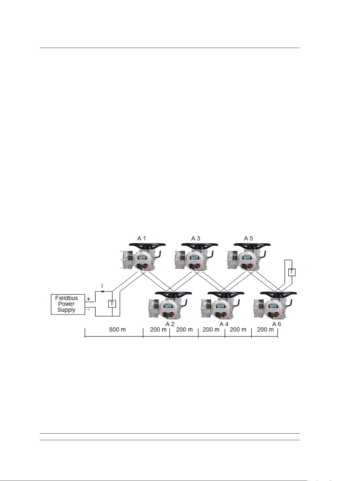
Example of voltage drop calculation:
Assume the cable is Type A (24 Ohm per km per conductor), the resistance of each 1000 metre pair
is 24 x 2 = 48 Ohms per km.
The current drawn by each node A1 to A6 is 20 mA.
Voltage drop Power supply to A1 = current x resistance
= (6 x 0.020) x (0.8 x 48) = 4.6 volts
Voltage drop A1 to A2 = (5 x 0.020) x (0.2 x 48) = 0.96 volts
Voltage drop A2 to A3 = (4 x 0.020) x (0.2 x 48) = 0.768 volts
Voltage drop A3 to A4 = (3 x 0.020) x (0.2 x 48) = 0.576volts
Voltage drop A4 to A5 = (2 x 0.020) x (0.2 x 48) = 0.384volts
Voltage drop A5 to A6 = (1 x 0.020) x (0.2 x 48) = 0.192volts
Total system volt drop = 4.6 + 0.96 + 0.768 + 0.576 + 0.384 + 0.192 = 7.48 volts
If the power supply is a 24 V unit, then the voltage at actuator A6 will be (24 – 7.48) = 16.52 volts
which is within the specified limits.
Whilst we have shown the power supply at one end of the segment, they can be fitted to the middle of
the network. This would reduce the voltage drop.
Fig 4.3: Voltage Drop Example
Page 26

Foundation Fieldbus CP Option Card Technical Manual
26 of 116 Publication PUB089-005-00_0618
4.3 Termination network
Each highway must be terminated correctly at the two ends of the data highway. The terminator
comprises at least one resistor and capacitor in series and they provide a characteristic impedance of
100 Ohm at 39 kHz. They need not be placed on the absolute ends of the highway but should be on
the ends of the main trunk section. They are usually incorporated inside the field junction box.
There are no highway termination facilities inside the actuator itself.
Page 27
Actuator Input Output Signals
Publication PUB089-005-00_0618 27 of 116
5 THE ACTUATOR INPUT AND OUTPUT SIGNALS
The FF CP card provides feedback data about its status and that of the actuator to the Foundation
highway. This data is contained in the Transducer function block and is fully listed in the section on
Function Blocks. The actuator is normally controlled by signals from the Foundation highway
connecting to the Output blocks and the Transducer block. There are local controls on the actuator
itself and there is the possibility to wire in direct contacts to control the movement. This section
explains the primary data available and the meaning of the signals generated by the actuator.
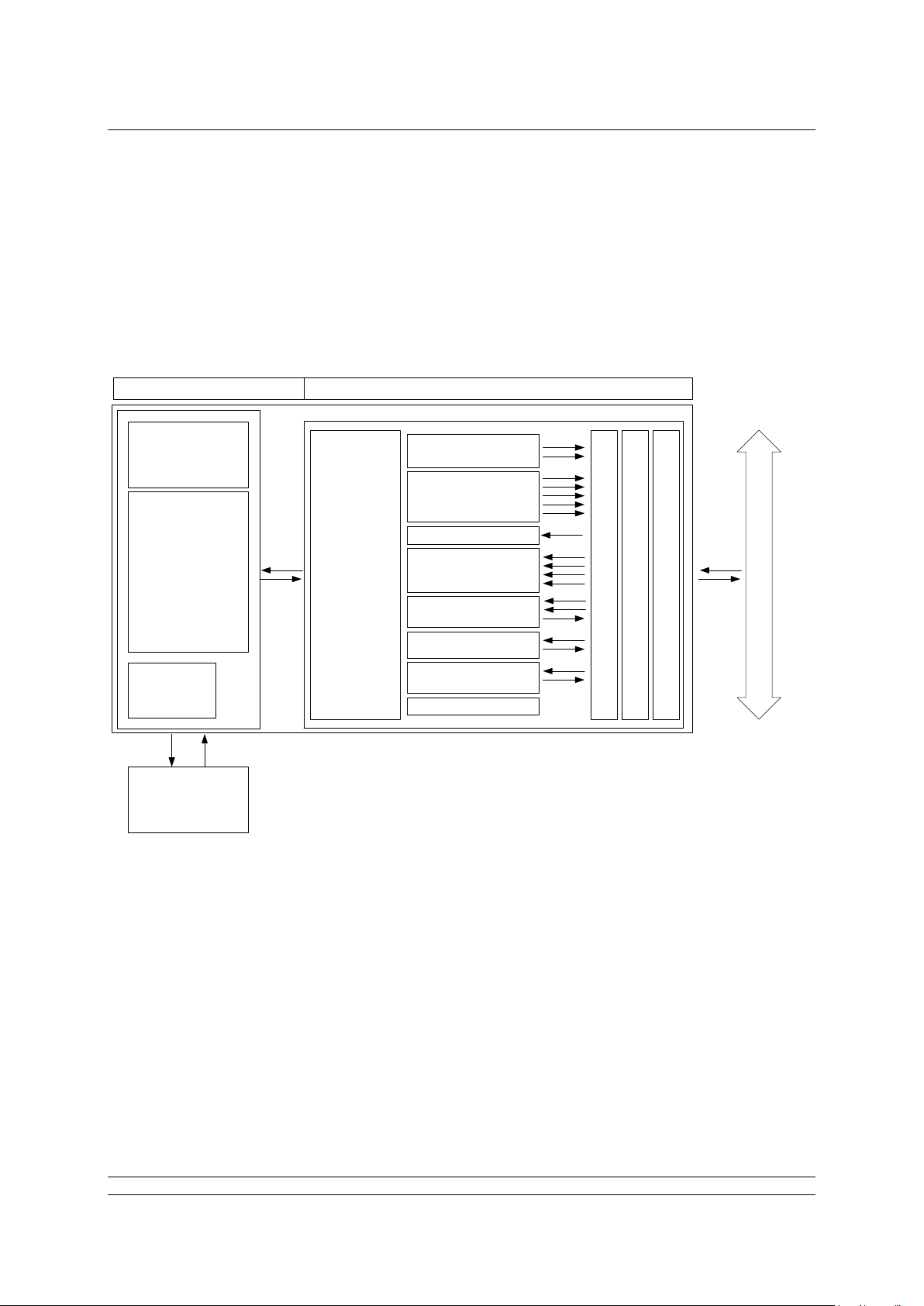
Actuator FF CP card
Motor &
Starter
Controls
Actuator
Control PCB
Local
Controls
Hard-wired
Control Inputs
& Outputs
Actuator
Interface
2 x AI
5 x DI
4 x DO
1 x PID
1 x CS
1 x Transducer
1 x Resource
Fieldbus Message Specification
Fieldbus Access Sublayer
Data Link Layer
1 x AO
FF H1 Data Highway
Input signals are those returned by the actuator to the network about the status of the actuator and
valve whilst output signals are those used to command the actuator to move or operate its internal
relays. An actuator control signal such as a command to open is an output, whilst a reported status
such as open limit switch reached is a feedback input.
Fig 5.1: Actuator and FF CP Card Block Diagram
Page 28

Foundation Fieldbus CP Option Card Technical Manual
28 of 116 Publication PUB089-005-00_0618
5.1 Controls
The FF CP card can be used to control the actuator and position the valve. The valve may be moved
fully closed, fully open or to an intermediate position. Additionally, the actuator can make the valve
adopt an Emergency Shut Down position and in some actuators perform a partial stroke test. Most
actuator types can be prevented from moving by the presence of an Interlocking signal from another
device on the plant. The actuator may also be operated from its local controls or by hard-wired direct
contact inputs. Note that to do this the Auxiliary Mask must be correctly set.
As well as controlling the actuator the FF CP can also be used to operate 4 discrete output relays
when the actuator is fitted with a relay card, assuming the DO block itself isn’t in IMAN, LO or OOS.
The control commands have three potential sources:
Foundation Fieldbus generated commands
Actuator Local Controls
Direct Hard-wired input controls
The full list of commands is shown in the table. The actuator types show whether the command is
applicable to that actuator type.
Command
IQ3, IQT3
& SI3
CVA &
CMA
CK
K
Foundation Network
Open
✓ ✓ ✓
✓
Close
✓ ✓ ✓
✓
Stop
✓ ✓ ✓
✓
Emergency Shut Down
✓ ✓ ✓
✓
Analogue Position Demand
✓ ✓ ✓
✓
Partial Stroke
✓ X ✓
X
Relay 1 output
✓
X
✓
X
Relay 2 output
✓
X
✓
X
Relay 3 output
✓
X
✓
X
Relay 4 output
✓
X
✓
X Local Actuator Controls
Open
✓ X ✓
✓
Close
✓ X ✓
✓
Stop
✓ X ✓
✓
Direct Hard-Wired Inputs
Open
✓ X ✓
✓
Close
✓ X ✓
✓
Stop/Maintain
✓ X ✓
✓
Emergency Shut Down / Net disable
✓ X ✓
✓
Open Interlock (active prevents opening)
✓ X ✓
✓
Close Interlock (active prevents closing)
✓ X ✓
✓
Note: – Requires an extra relay board to be fitted.
Fig 5.2: Available command options
Page 29

Actuator Input Output Signals
Publication PUB089-005-00_0618 29 of 116
The FF commands operate on the Transducer block through Digital Output (DO) blocks that are
already connected in the default configuration. The network commands will operate the actuator
provided:–
• Local/Local Stop/Remote selector is in ‘Remote’ (or “Run” in a CVA).
• Foundation commands are not inhibited by the ‘Inhibit/HW_DI-4’ input parameter setting
and HW_DI-4 condition.
• No interlock is active.
• There is no active hard-wired control input or FF control input present.
• No alarm condition prevents the actuator from moving.
• The Transducer and Resource blocks are in AUTO.
Open A digital command to cause the actuator to open to the fully open
position as indicated by the Open limit switch. Under correct operation
the actuator stops either when the open limit switch is reached, when
the torque exceeds the value set and the open limit switch has been
reached, or a new command is sent over the network.
Close A digital command to cause the actuator to close to the fully closed
position as indicated by the Close limit switch. Under correct operation
the actuator stops either when the close limit switch is reached, when
the torque exceeds the value set and the close limit switch has been
reached, or a new command is sent over the network.
Stop With no other command present, this digital command causes an
actuator motor that is running to stop.
Emergency Shut Down
A digital command that causes the actuator to drive to its Emergency
position. There are settings within the actuator to determine if this is a
closed, open or stay-put action.
Analogue Position Demand
This function is only available over the Foundation network. To initiate
Analogue Position Control this bit must be set to 1 and all other
actuator control bits must be set to 0. This enables the AO block to
function. The actuator will then move to within the deadband of
whatever position value has been set in the AO block output
parameter (range 0-100%, resolution 0.1%).
Provided limited range positioning is not invoked, the values 0% and
100% written to the AO output parameter produce a special case
output where the command is revised so as to fully close the valve to
its tight shut-off position (0%) and to fully open the valve (100%).
Note:
Many multi-turn actuators are set to open until the open limit switch is reached and close until
the closing on torque switch trips, but it is dependent on the type of valve. The quarter turn
actuators normally operate 90-degree valves, use stop-bolts on the actuator or gearbox, and
stop when these are reached. The control room indication is always taken from the end of travel
limit switch settings
Page 30

Foundation Fieldbus CP Option Card Technical Manual
30 of 116 Publication PUB089-005-00_0618
Note:
The following functions are not an option with all actuators – see Fig: 5.2.
Partial Stroke The actuator will move the valve to an intermediate position and back
to the start position provided it is at the correct end of travel position
when the command is issued. The end to start from and the amount of
travel are selected by parameters in the transducer block.
Relay Output 1 to 4
These 4 commands are used to energise and de-energise the internal
relays on the additional relay board (if fitted). (These outputs are
referred to as S5-S8 in the standard actuator documentation when
there is no FF CP card in the actuator). The resulting outputs can be
used for operating other equipment such as a pump or indication light.
The actuator itself is not able to control these relays directly from the
main board when the FF CP card is fitted; they may only be controlled
by the DO blocks. They will maintain their last state if power is
removed from the actuator. On restoration of power, the relays will be
reset to their de-energised condition.
Hard-Wired Open and Close
These commands operate the actuator in the same way as the open
and close commands sent over the Foundation highway, assuming
the auxiliary input mask has been set correctly.
Hard-Wired Stop The hard-wired stop input acts as a change of state input. If the
actuator is moving, opening the Stop input will stop the actuator. If the
Stop input is already open and a Foundation DO command is sent to
the actuator, the Foundation command will be initiated. To stop the
actuator the hard-wired input must be closed and opened again.
Hard-wired ESD (Network Disable)
The hard-wired ESD may be set to causes the actuator to drive to its
Emergency position. Alternatively, the input can be used to disable
Foundation network control. The function of the input is determined by
a parameter in the transducer block.
Page 31

Actuator Input Output Signals
Publication PUB089-005-00_0618 31 of 116
5.1.1 Controls priority
Since there can be several potential sources for control inputs the actuator and FF CP card assigns a
priority for those occasions when two or more commands are applied simultaneously.
Local controls go direct to the main board and override any Foundation controls and any hard-wired
controls except hard-wired ESD. An actuator that has Local selected cannot be controlled over the
Foundation network.
In addition, the remote control hard-wired inputs can be used as discrete input signals, to report the
status of other devices or as control inputs. The associated Auxiliary Input Mask parameter must be
set to select the required function. When selected for control, the hard-wired inputs take priority over
the Foundation controls, but are subordinate to the local controls (except for ESD). If there is a
Foundation command still present when a Local or Hard-wired command is removed, the Foundation
command will re-assert itself.
In the case of the hard-wired input for ESD, this can be configured either as an ESD/HW_DI-4 signal
or as a ‘Foundation Command Inhibit’ to prevent network control signals from moving the actuator.
High Priority Low Priority
Local Stop Local Close Hard-Wired Close
Foundation Close
Local Open Hard-Wired Open Foundation Open
Hard-Wired ESD Hard-Wired Stop Foundation Stop
Foundation ESDFoundation Position
Foundation Part Stroke
Mechanically interlocked to prevent both at the same time.
The actuator can be set so that Local Stop has a higher priority than ESD.
Only one Foundation command should be applied at a time.
If a Foundation command is applied whilst Hard-Wired Stop is present, stop is cancelled.
Fig 5.3: Controls Priorities
Page 32

Foundation Fieldbus CP Option Card Technical Manual
32 of 116 Publication PUB089-005-00_0618
5.1.2 Foundation control using DO blocks only
Discrete action control is achieved using the DO blocks in the FF CP card. Each DO block output has
a value between 0 and 255. If the host DCS system uses its ‘Boolean Fan In’ function, most of the
discrete controls can be achieved using one DO block – see table below. The selected block is put in
service and the appropriate value sent to its output. Only one value is permitted at a time in each
block. If Boolean functions are not available, then several blocks may need to be used to achieve the
desired control actions.
DO Block Output Actions
Block No.
Bit 0
Bit 1
Bit 2
Bit 3
Bit 4
Bit 5
Bit 6
Bit 7
DO 1
Close
Open
Stop
ESD
Position
RLY 1
RLY 2
RLY 3
DO 2
Open
Close
Stop
ESD
PST
RLY 1
RLY 2
RLY 3
DO 3
Stop
Close
Open
Position
RLY 1
RLY 2
RLY 3
RLY 4
DO 4 Mode 0
Position
Close
Open
ESD
RLY 1
RLY 2
RLY 3
RLY 4
DO 4 Mode 1
ESD
Close
Open
Position
RLY 1
RLY 2
RLY 3
RLY 4
DO 4 Mode 2
RLY 1
Close
Open
ESD
Position
RLY 2
RLY 3
RLY 4
DO 4 Mode 3
PST
Close
Open
ESD
RLY 1
RLY 2
RLY 3
RLY 4
DO 4 Mode 4
Analogue block control (AO) only
DO 4 Mode 5
0 = Close, 1 = Open, any other value Stop
DO 4 Mode 6
Position
PST
Close
Open
Stop
ESD
RLY 1
RLY 2
Fig 5.4: DO Block Options
Select Multiple/Single bit control in the Transducer block.
Enable the appropriate DO blocks.
If DO 4 is being used, set its mode in the Transducer block.
The Transducer block includes parameters to select single or multiple bit support.
- If multiple bit support is available (using Boolean Fan In) only one block may be used.
- If single bit control is selected, all four blocks can be used but each block uses Bit 0 only.
The action of DO 4 is selected using the mode control parameter in the Transducer block.
5.1.3 Foundation control using the AO block only
In order to place the FF CP card into position control mode, so that the AO block output values
determine the actuator position, it is necessary to set the Control Mode in the Transducer block to
Mode 4. The actuator will then use the value of the AO block output as the setpoint for the internal
positioner and the actuator will move to the setpoint (subject to the status of the Local and Hard-wired
controls, the Interlocks and the actuator deadband and hysteresis settings). Output block DO 4 does
not need to be added to the schedule and can remain set Out of Service (OOS).
Set the Mode Control in the Transducer block to Mode 4.
Set the positioner parameters (hysteresis, deadband, motion inhibit time etc.).
Page 33

Actuator Input Output Signals
Publication PUB089-005-00_0618 33 of 116
If the AO output is set to 0% and limited range positioning is not being used (selected via the
Transducer block), the actuator will operate as though a ‘close’ command had been sent. Similarly, if
the AO output is set to 100% under these conditions, the actuator will interpret the instruction as an
‘open’ command.
Note that when limited range positioning is used and the actuator is in the range from fully closed to
the 0% position, an AO command of 0% will not be acted upon. Likewise, if the actuator is in the
range from fully open to the 100% position, an AO command of 100% will not be acted upon. See
section 6.2.4 for more information on limited range positioning.
5.1.4 Foundation control using both DO and AO blocks
With mixed position control using the AO and discrete (open/stop/close/ESD) control using the DO
blocks, the control settings must be carefully observed. Discrete actions will take priority over the
Position requests.
The single/multiple bit control option for the discrete controls has to be determined. When Boolean
Fan In is available, multiple bit control is set and a single DO block is used for the open/stop/close
discrete control actions. The DO block chosen must also include a condition to select Position Control.
With single bit control each discrete action requires a DO block to be enabled and the Position option
is in DO 4 which must be set to Mode 0.
When the AO value is to be adopted for the valve position, the control scheme must select the DO
block to be in its Position value. With multiple blocks DO 4 must be set to ‘1’, all the others being ‘0’.
As soon as the discrete control changes to ‘Position’, the AO output value becomes the desired
actuator position and the position controller will move the valve.
DO control values of Open/Stop/Close/ESD have priority over the AO value.
The DO value must equal ‘Position Control’ for the AO value to become active.
The position controller will be subject to the considerations mentioned in 5.1.3 with regard to 0% and
100% values.
Page 34

Foundation Fieldbus CP Option Card Technical Manual
34 of 116 Publication PUB089-005-00_0618
5.1.5 The ‘S’ contacts (RLY 1 to RLY 4) controlled by the DO blocks
Note:
This option is not available on all actuator types, see fig 5.2.
The actuator has four ‘S’ contact outputs that may be configured to report the status of the actuator
with signals such as Open Limit, Closed Limit etc. These are identified as S1 to S4.
In addition, an optional additional relay board can be fitted with four more relays. The status of these
relays is then adjusted by Foundation DO block commands on outputs Relay 1 to Relay 4. Setting the
appropriate DO block output to the value corresponding to the relay will energise the relay whilst the
output from the DO is present. Setting a different value will de-energise the relay. Note that these
relays are latching and, if energised, will not change state when the actuator power is removed. On
restoration of power the relays will be reset to their de-energised condition.
5.1.6 Foundation network control disable feature
Note:
This option is not available on all actuator types, see fig 5.2.
It is possible to set the ESD/HW_DI-4 input so that the actuator ignores open, stop, close, ESD, PST
and position control signals sent over the Foundation network. If the HW_DI-4 ESD / Net Disable
parameter in the Transducer block is set to ‘1’ then when the ESD input connection is detected as
being logic 1, Foundation control is not allowed. This feature is dependent of the Auxiliary mask
setting and can be configured as an NO or NC input. When the HW_DI-4 ESD / Net Disable parameter
is set to ‘1’, no hard-wired ESD will be available.
Fig 5.5: Actuator relay outputs
Actuator
Controller
PCB
S1 – S4
S5 – S8
Relays 1 - 4
FF CP
card
Relay PCB
Page 35

Actuator Input Output Signals
Publication PUB089-005-00_0618 35 of 116
5.2 Discrete Input status feedback
The FF CP card has DI (Discrete Input) function blocks that may be used to report the valve and
actuator status over the network. The conventional contact indications are also available from the
actuator limit switches and indication contacts.
Each DI block output has a value between 0 and 255. If the host DCS system uses its ‘Boolean Fan
Out’ function, the returned value may be decoded into 8 individual bits, where each bit represents a
single piece of feedback data. If the DCS does not have this facility, then the state of the first bit in
each DI will be represented by 0 = not true and 1 = true. The complete list of DIs and the function of
the individual bits is indicated in section 5.2.1. The table below indicates which signals are available
from each actuator type.
DI Function:
Block Number/Bit Number
Status Feedback
IQ3,
IQT3
& SI3
CVA
&
CMA
CK
K
1 / 0
2 / 1 Close Limit
✓ ✓ ✓
✓
1 / 1
2 / 0 Open Limit
✓ ✓ ✓
✓
1 / 2 5 / 0
Actuator Moving
✓ ✓ ✓
✓
1 / 3
2 / 3 Running Closed
✓ ✓ ✓
✓
1 / 4
2 / 2 Running Open
✓ ✓ ✓
✓
1 / 5
3 / 0
Remote selected
✓ ✓ ✓
✓
1 / 6
3 / 1
Local Stop selected
✓ ✓ ✓
✓
1 / 7
3 / 2
Local selected
✓ ✓ ✓
✓
2 / 4 Not in Remote
✓ ✓ ✓
✓
2 / 5
4 / 0
General Alarm
✓ ✓ ✓
✓
2 / 6 Valve Obstructed
✓ ✓ ✓
✓
2 / 7 Valve Jammed
✓ ✓ ✓
✓
3 / 3
Moving Inhibited
✓ ✓ ✓
✓
3 / 4
5 / 5
Open Interlock active input
✓ ✓ ✓
✓
3 / 5
5 / 6
Close Interlock active input
3 / 6
Position Control Enabled
✓ ✓ ✓
✓
3 / 7
Slow Mode
4 /1 Thermostat Tripped
✓ ✓ ✓
✓
4 / 2
Monitor Relay
✓ ✓ ✓
✓
4 / 3
Valve Obstructed/Jammed
✓ ✓ ✓
✓
4 / 4
Part Stroke Error
✓ ✓ ✓
✓
4 / 5
Valve Moving by Hand
✓ ✓ ✓
✓
4 / 6
Battery Low
✓
N/A
N/A
N/A 4 /7 Watchdog Recovery
✓ ✓ ✓
✓
5 / 1
Hard-Wired HW_DI–1
✓
N/A
N/A
N/A
5 / 2
Hard-Wired HW_DI –2
✓
N/A
N/A
N/A
5 / 3
Hard-Wired HW_DI –3
✓
N/A
N/A
N/A
5 / 4
Hard-Wired HW_DI –4
✓
N/A
N/A
N/A
5 / 7
Partial Stroke in Progress
✓ ✓ ✓
✓
Notes over page:
- This bit is reported when within the slow mode band, but does not affect the actuator. Slow mode
is not an option in some of the actuators.
- This bit indicates the state of the Hardwired Partial stroke input
Page 36

Foundation Fieldbus CP Option Card Technical Manual
36 of 116 Publication PUB089-005-00_0618
5.2.1 Discrete Inputs
Close Limit This data bit indicates that the actuator has reached the closed
position. The limit switch should be set slightly within the actual valve
stroke to allow for torque seating or overshoot on closing without
damaging the valve. The data bit will remain true (1) even if the
position is passed through or exceeded.
Open Limit This data bit indicates that the actuator has reached the open position.
The limit switch should be set slightly within the actual valve stroke to
allow for torque seating or overshoot on opening without damaging
the valve. The data bit will remain true (1) even if the position is
passed through or exceeded.
Actuator Moving Whenever the actuator position is changing due to the motor running
or in the case of the IQ or IQT if the output drive is moving, this bit will
be set true (1).
Running Closed Whenever the actuator motor contactor used to drive the actuator in
the closing direction is energised this bit will be true (1).
Running Open Whenever the actuator motor contactor used to drive the actuator in
the opening direction is energised this bit will be true (1).
Remote Selected This bit is true (1) when the actuator three-position Remote/Local
Stop/Local selector is in the Remote position. The selector must be in
this position for Foundation control to be permitted.
Local Stop The actuator three-position selector passes from Local to Remote or
Remote to Local through the Local Stop position. The switch can also
be placed in Local Stop. When the switch is in the Local Stop position
this bit will be true (1). Remote control of the actuator is not possible
when the selector is in this position.
Local Selected This bit is true (1) when the actuator three-position Remote/Local
Stop/Local selector is in the Local position. Remote control of the
actuator is not possible when the selector is in this position.
Not In Remote This bit is true (1) when the actuator three-position Remote/Local
Stop/Local selector is not in the Remote position. The selector will be
in either the Local or Local Stop position. Remote control of the
actuator is not possible when the selector is in this position.
Page 37

Actuator Input Output Signals
Publication PUB089-005-00_0618 37 of 116
General Alarm If any of the following conditions are true this bit will be true (1):–
Thermostat tripped
Monitor Relay
Valve Obstructed
Valve Jammed
Manual Movement
Valve Obstructed This bit will be true (1) if the actuator stops in mid-travel when not
expected to do so after receiving a command to move. If the actuator
torque exceeds the trip value set during commissioning, then the
motor will stop and motion will cease. The reason for the actuator
stopping will be the high torque due to an obstruction and not a ‘Stop’
signal or reaching the desired setpoint position.
The bit will remain true (1) until the actuator position changes by 2%
or more.
Valve Jammed This bit will be true (1) if the actuator is stationary at the end of travel
and fails to move away from the seat of the valve when a network
command requests it to do so. The actuator will trip on excessive
torque due to the valve being jammed in the seat. The FF CP card
fails to see movement and reports this status after the time set in the
associated Transducer block parameter during set-up.
The bit will remain true (1) until the actuator position changes by 2%
or more.
Moving Inhibited This bit will be true (1) when the Motion Inhibit Timer is active or the
Interrupter Timer is active, or both are active.
The Motion Inhibit Timer is used in position control to prevent the
actuator from exceeding its prescribed number of starts per hour, or to
reduce the effects of hunting during closed-loop control.
The Interrupter Timer can be used over part or the entire actuator
stroke to slow down the effective speed of valve travel.
When under network control, the control signal does not need to be
re-applied when this bit is true, as the control action will continue once
the time has elapsed.
Note: Attempting to restart the actuator to move towards the obstruction (even if the
obstruction no longer exists) is not possible, the actuator will not restart. The actuator
must be electrically reversed away from the obstruction before attempting to continue in
the original direction.
Note: Attempting to restart the actuator to move out of the seated position is not possible. The
actuator must be reversed before it will run in the same direction again. The jammed
seat must first be released manually before electrical control is attempted. The problem
may be overcome by adjusting the actuator torque setting, which is designed to provide
extra power on leaving the seated position.
Page 38

Foundation Fieldbus CP Option Card Technical Manual
38 of 116 Publication PUB089-005-00_0618
Open Interlock The input contact to the Open Interlock is monitored. Whenever the
input contact is closed this bit will be true (1). If the actuator is not
using the interlock function, then this input can be used as a digital
status feedback for a plant signal not associated with the actuator. If
the interlock circuit is being used, then permission must be granted
before the actuator can be opened. The presence of this bit will
indicate that opening is permitted and permission is granted.
Close Interlock The input contact to the Close Interlock is monitored. Whenever the
input contact is closed this bit will be true (1). If the actuator is not
using the interlock function then this input can be used as a digital
status feedback for a plant signal not associated with the actuator. If
the interlock circuit is being used, then permission must be granted
before the actuator can be closed. The presence of this bit will
indicate that closing is permitted and permission is granted.
Position Control Enabled
This bit will be true (1) when a Position command is being actioned.
This data can be used to indicate that positioning mode has control of
the actuator.
Thermostat If the temperature of the motor windings rises above the thermostat
trip value, the thermostat contact will open and this signal will be
present (1). There are no adjustments for the temperature at which
the thermostat trip operates. The motor will be stopped if the
thermostat trips. Only once the motor (or transformer) has cooled
down and the thermostat has reset itself can a new Remote, Host or
Local command to move the actuator be carried out. A setting on the
actuator main board allows the ESD command to override the
thermostat. The bit will remain set at logic 1 until the thermostat resets
itself.
Monitor Relay This signal is true (1) when actuator remote control is not available.
The actuator Monitor Relay status is a composite signal for several
alarms. This signal will be set true if the actuator selector is in Local or
Local Stop (not in Remote) or if the thermostat trips.
Note on an IQ3/IQT3 actuator the Monitor Relay can be set to
trigger on “Available” or “Alarm”. When set to Alarm, Local or
Local Stop won’t cause a monitor Relay Alarm – see section 2.2
of PUB002-040: http://www.rotork.com/master-popup/8953/
The mains supply is always monitored and if one of the three phases
is lost, this bit is set. If the actuator is operated from a single phase
supply and this is lost, then communications with the actuator will also
be lost. Where a 3-phase supply is used, if the phase associated with
the control circuits is lost then communications with the actuator will
be lost.
Page 39

Actuator Input Output Signals
Publication PUB089-005-00_0618 39 of 116
Valve Obstructed/Jammed
This bit is a combination of the Valve Obstructed and the Valve
Jammed bits. If either is true this bit will be true (1).
Valve Moving by Hand
The manual movement of the valve is reported as true (1) if the
actuator is moved by the handwheel away from the last position. The
percentage of travel required to trip the indication is set in the
associated parameter in the Transducer block during set-up.
The bit will remain true (1) until the actuator is moved electrically by
either the local controls or a network command.
Digital Input HW_DI-1
This bit reports the status of the contact connected to the actuator
hard-wired Open terminals. The input can be used to control the
actuator or simply to report the status of a plant feedback signal. The
function is set in the Auxiliary Input Mask parameter, which
determines whether the bit is reported as true (1) for a closed contact
or an open contact and whether the input controls the actuator or not.
Note that the input is always reported even when it is also controlling
the actuator.
Digital Input HW_DI-2
This bit reports the status of the contact connected to the actuator
hard-wired Close terminals. The input can be used to control the
actuator or simply to report the status of a plant feedback signal. The
function is set in the Auxiliary Input Mask parameter, which
determines whether the bit is reported as true (1) for a closed contact
or an open contact and whether the input controls the actuator or not.
Note that the input is always reported even when it is also controlling
the actuator.
Digital Input HW_DI-3
This bit reports the status of the contact connected to the actuator
hard-wired Stop/Maintain terminals. The input can be used to control
the actuator or simply to report the status of a plant feedback signal.
The function is set in the Auxiliary Input Mask parameter, which
determines whether the bit is reported as true (1) for a closed contact
or an open contact and whether the input controls the actuator or not.
Note that the input is always reported even when it is also controlling
the actuator.
Page 40

Foundation Fieldbus CP Option Card Technical Manual
40 of 116 Publication PUB089-005-00_0618
Digital Input HW_DI-4
This bit reports the status of the contact connected to the actuator
hard-wired ESD terminals. The input can be used to control the
actuator or simply to report the status of a plant feedback signal. The
function is set in the Auxiliary Input Mask parameter, which
determines whether the bit is reported as true (1) for a closed contact
or an open contact and whether the input controls the actuator or not.
Note that the input is always reported even when it is also controlling
the actuator.
A configuration feature also allows HW_DI-4 to be set to act as a
‘Disable Fieldbus Control’ input. In this mode, when the input is
applied (irrespective of the Auxiliary Mask setting) the actuator cannot
be controlled over the network. This can be useful during plant
commissioning to prevent unwanted valve movement.
5.2.3 Discrete Inputs reporting the FF CP card condition
Watchdog Recovery
The FF CP card’s watchdog automatically resets the processor if it is
tripped. This bit will be true (1) following a watchdog trip for the time
period set in the associated watchdog timeout parameter.
Part Stroke Error In order to perform a partial stroke of the valve, the starting position is
specified as either the open limit or the close limit. If the actuator is
commanded to perform a partial stroke when it is not in the correct
starting position or when it is in a mid-position, this error is generated
and the bit will be set (1).
There is a timer associated with Partial Stroke that is set in the
Transducer block during set-up. It must be set to a value long enough
to cover a successful part stroke operation from end to mid-position
and back to the end. If the actuator fails to complete the partial stroke
within the time set, then this bit will be true (1).
Once set, the Part Stroke Error bit will be reset to 0 when the actuator
next moves at least 2% by either a manual or automatic operation.
Partial Stroke in Progress
When the actuator is performing a partial stroke this bit is true (1).
Once the action is complete the bit is reset (0). If the partial stroke is
interrupted by a new command then the bit will be reset.
Page 41

Actuator Input Output Signals
Publication PUB089-005-00_0618 41 of 116
5.3 Actuator Analogue Input feedback
The FF CP card includes two Analogue Input blocks, AI 1 and AI 2, which are used to report
information about the valve and actuator. These blocks are connected to the Transducer block in the
default configuration.
Function Block
No
Analogue Feedback
IQ3,
IQT3
& SI3
CVA
&
CMA
CK
K
AI 1
Valve Position
✓ ✓ ✓
✓
AI 2
Actuator Instantaneous
Torque/Thrust
✓ ✓ ✓
N/A
Valve Position The current valve position is reported as an Integer Value in the range
0.0 to 100.0% in block AI 1.
The actuators automatically scale the valve position value reported
from the setting of the limit switches. This scaling is retained in
EEPROM when the actuator power is removed.
If Limited Range Positioning is invoked by setting the appropriate
parameters, then the reported valve position 0.0 to 100.0% follows the
limited range of valve travel.
Torque The currently developed torque value is reported in block AI 2 in the
range 0 to 120% representing the percentage of actuator rated torque
generated.
Page 42

Foundation Fieldbus CP Option Card Technical Manual
42 of 116 Publication PUB089-005-00_0618
This page has been left intentionally blank
Page 43

Actuator Input Output Signals
Publication PUB089-005-00_0618 43 of 116
6 FUNCTION BLOCKS
Function blocks provide the heart of the Foundation Fieldbus system. Each device on a network
includes at least one Transducer block and a Resource block to allow the equipment to be configured
to operate on the network.
The FF CP card includes 16 blocks, of which one is the Resource block and one is the Transducer
block. The remaining 14 input and output blocks are used to control and collect data from the actuator.
In order to make the FF CP easier to use, all of the parameters in the blocks are already defined. The
Foundation requires certain parameters to be set to specific default values. The actuator controller will
require the alteration of some of these when a particular function block is to be used. The values can
be altered using a suitable configuration tool. Some of the network communications link location data
(VCR coding) are already defined, as required by the Foundation specifications. Publisher and
Subscriber function blocks have VCR values assigned, as described in the DD file. The pre-assigned
connections that are fixed include:
The two AI blocks to the two analogue input variables in the actuator.
The AO block to the resident analogue output positioner in the actuator.
The four DO blocks to the digital outputs for controlling the open/close actions of the
actuator.
The five DI blocks to the digital inputs for reporting actuator status to the network.
Many of the features of the function blocks are provided in order to allow the system to automatically
identify and use these blocks. The Fieldbus specification FF-890 to FF-892 defines all aspects of the
function blocks. In practice, the user needs to know very little about the internal workings of the blocks,
as the Capabilities file lists all the available features. A suitable configuration tool such as that supplied
by National Instruments can be used to set up all the tag names and operation of the blocks in the
complete system. The contents of the blocks can also be examined using a configuration tool. Most
DCS systems include configuration utilities for Foundation Fieldbus devices.
Each block must have its own unique tag name allocated during system configuration and each block
has at least three modes it can be in, which show its availability on the system (OOS – Out Of Service,
Auto – local set point used for the primary output value algorithm, CAS – set point value from the Cas
input is used for the primary output value algorithm).
Fig 6.1: Function blocks within the FF CP card
Page 44

Foundation Fieldbus CP Option Card Technical Manual
44 of 116 Publication PUB089-005-00_0618
6.1 Resource Block
Every Fieldbus device includes a resource block that describes to the host controller the system
resources the device needs. This block contains data that is specific to the FF CP card itself. There
are no links to this block and there is no function schematic. All the standard Resource Block
parameters are included, with the addition of read only data shown in the following table that is
specific to the FF CP card.
Index
Parameter
Description
Units
Class
1
ITK_VER
ITK version tested to
None
RO
2
SW_REV
Firmware revision of FIC
None
RO
3
MB_REV
Main or Interface board firmware revision
None
RO
4
DEVICE_STATUS1
Special device status parameters
None
RO
5
DEVICE_STATUS2
Special device status parameters
None
RO
6
DEVICE_STATUS3
Special device status parameters
None
RO
7
DEVICE_STATUS4
Special device status parameters
None
RO
8
DEVICE_STATUS5
Special device status parameters
None
RO
9
ACT_DEVICE_STATUS
Special device status parameters
None
RO
Indexes 1 to 3 contain information for ITK test and Rotork firmware version control.
Indexes 4 to 9 give information on the current status of the various function blocks and the actuator
control interface as shown below.
Index 4: DEVICE_STATUS1
Bit
Title
Description
0
Simulate enable jumper on
The Simulation enable switch is ON
1
2
3 4
RB in OOS mode
The Resource block is OOS
5
6
7
8
EEPROM failure
The EEPROM has failed on the FIC
9
10
11
12
Page 45

Actuator Input Output Signals
Publication PUB089-005-00_0618 45 of 116
Index 5: DEVICE_STATUS2
Bit
Title
Description
0
No response from Actuator controller
There is a communications failure between the Fieldbus
and actuator
1
2
3 4
Checksum error
Checksum error on the FIC
5
6
7
8
TB in OOS mode
Transducer block is in OOS mode
9
10
11
Index 6: DEVICE_STATUS3
Bit
Title
Description
0
AI 1 in OOS mode
AI 1 is in Out of Service mode
1
AI 1 in MAN mode
AI 1 is in Manual mode
2
AI 1 in Simulate active
AI 1 simulation is active
3
4
AI 2 in OOS mode
AI 2 is in Out of Service mode
5
AI 2 in MAN mode
AI 2 is in Manual mode
6
AI 2 in Simulate active
AI 2 simulation is active
7
8
DI 1 in OOS mode
DI 1 is in Out of Service mode
9
DI 1 in MAN mode
DI 1 is in Manual mode
10
DI 1 in Simulate active
DI 1 simulation is active
11
12
DI 2 in OOS mode
DI 2 is in Out of Service mode
13
DI 2 in MAN mode
DI 2 is in Manual mode
14
DI 2 in Simulate active
DI 2 simulation is active
15
16
DI 3 in OOS mode
DI 3 is in Out of Service mode
17
DI 3 in MAN mode
DI 3 is in Manual mode
18
DI 3 in Simulate active
DI 3 simulation is active
19
20
DI 4 in OOS mode
DI 4 is in Out of Service mode
21
DI 4 in MAN mode
DI 4 is in Manual mode
22
DI 4 in Simulate active
DI 4 simulation is active
23
24
DI 5 in OOS mode
DI 5 is in Out of Service mode
25
DI 5 in MAN mode
DI 5 is in Manual mode
26
DI 5 in Simulate active
DI 5 simulation is active
27
Page 46

Foundation Fieldbus CP Option Card Technical Manual
46 of 116 Publication PUB089-005-00_0618
Index 7: DEVICE_STATUS4
Bit
Title
Description
0
PID1 in OOS
PID block is Out of Service
1
2
3
4
PID1 Bypass
PID1 has bypass active
5
6
7
Index 8: DEVICE_STATUS5
This index is reserved for future use.
Index 9: ACT_DEVICE_STATUS
Bit
Title
Occurs When
Action Required
Effect
0
DO block control
conflict
Usage of more than
one DO block. (When
support for multiple bits
is selected this is not
allowed).
Check for multiple DO blocks
in service, when multiple bit
support is selected in TB, and
not in mode 4 – (AO only
control).
FIC Actuator operation
suspended.
1
Incorrect control
of DO block
Single bit support has
been selected, but
multiple bits are being
received.
Check for multiple bits being
set in DO blocks when only
single bit support is selected
in TB.
FIC Actuator operation
suspended.
2
Controls
contention
More than one actuator
control bit is currently
active.
Check for more than one bit
being true in the actuator
digital control register.
FIC Actuator operation
suspended.
3
Actuator interface
offline
The actuator is
powered down or there
is a fault between the
Fieldbus and Actuator
interface.
No communications between
the actuator control/main PCB
and the FIC.
Actuator operation not
possible over FF
network.
4
FF is overridden
FF control of actuator
is currently disabled.
Actuator status is Local or
Local Stop and/or HW_DI-4
net disable function is
switched on and active.
Actuator operation not
possible over FF
network.
Page 47

Actuator Input Output Signals
Publication PUB089-005-00_0618 47 of 116
6.2 Transducer Block
The Transducer Block is at the heart of the function block structure in the FIC. It contains all of the
information with regards to setup and control of the actuator as well as its status feedback and
provides the link between standard function blocks and the actuator mechanisms. Links between the
actuator hardware and transducer block are already made to allow the user to access defined settings
for the device.
The links between the Transducer block and the Input / Output function blocks are also defined and
may not be altered. Data may be read from the parameters but not all parameters permit write
commands. Writes are limited to the parameters used to set up the actuator control functions.
Before the actuator is used, the settings associated with its performance must be adjusted to match
the application for the valve. These settings are contained in parameters within the Transducer block.
On installing the card,
The default values in the table will be present.
Parameter values should be adjusted to allow for the desired control of the actuator.
6.2.1 Transducer block parameters
The table lists all the parameters in the Transducer block. Many of these are required by the
Foundation standards and are necessary for the card to operate on the highway. In addition, the block
contains many more parameters that are actuator or set-up related. The parameters are categorised
as follows:
Index
Description
1-23 / 93-95
FF specific parameters / standard requirements
24-29
Status feedback from the actuator – text format
30-36
Status feedback from the actuator – numerical format
37-49
Discrete and analogue output values to the actuator
50-63
Actuator parameter setup
64
Status feedback – date format
65-66
FF parameter setup
67-92
Actuator Datalogger information
The parameters contained in the table below have the following attributes:
• Range is the range of the parameter. Where ’value’ is stated, then this is the decimal value.
Where ‘bits’ are stated, then these are bit parameters starting at bit 0.
• Default is the default value for the parameter.
• Units are the unit type for the parameter (E – enumeration, S – String).
• Class is whether the parameter is read-only (RO) or read-write (RW).
Note: The Transducer Block MUST be placed in OUT OF SERVICE MODE (OOS) before
changes can be made to the Control Mode or Discrete Block Control parameters.
Page 48

Foundation Fieldbus CP Option Card Technical Manual
48 of 116 Publication PUB089-005-00_0618
Index
Parameter
Description
Range
Default
Units
Class
1
ST_REV
Revision level of the static
data
Positive
0
None
RO
2
TAG_DESC
User description of the
intended application of the
block
32 characters
Null
N/A
RW
3
STRATEGY
Used to identify grouping of
blocks
0 None
RW
4
ALERT_KEY
ID No. of the plant unit
1 to 255
0
None
RW
5
MODE_BLK
Actual, target, permitted, and
normal modes of the block
OOS
N/A
RW 6 BLOCK_ERR
FF specific parameter:
Block Error Status
None
RO 7 UPDATE_EVT
Alert is generated by any
change to the static data
N/A
RW 8 BLOCK_ALM
Alarm for all problems in the
block
N/A
RO
9
TRANSDUCER_DIRECTORY
Directory that specifies the
number and starting indices
of the transducers
None
RO
10
TRANSDUCER_TYPE
Identifies the transducer.
100 E RO
11
XD_ERROR
Error Codes
0 None
RO
12
COLLECTION_DIRECTORY
FF specific parameter
None
RO
13
ACT_MAN_ID
Manufacturer ID, i.e. Rotork
0xFF01
65281
E
RO
14
ACT_MODEL
Actuator model number / type
Value / type:
0 – Unknown (default)
2 – A,AQ,Q, Integral
6 – IQ
8 – IQT
9 – EH
10 – Skilmatic
11 – Multiport
12 – CVL
13 – CVQ
14 – Rompak
17 – IQ3
18 – IQT3
20 – CMA
21 – SI3
22 – K range
23 – CK2
0
None
RW
15
ACT_SN
Actuator serial number
Null
None
RW
16
ACT_DEVICE_STATUS
Rotork parameter
Copy of Resource block
parameter
0
None
RO
17
XD_CAL_LOC
Calibration Location
Null
None
RW
18
XD_CAL_DATE
Calibration Date
0 None
RW
19
XD_CAL_WHO
Person Who calibrated
Null
None
RW
20
VALVE_MAN_ID
Valve Manufacturer’s ID
Null
None
RW
21
VALVE_MODEL_NUM
Valve Manufacturer’s Model
Null
None
RW
Page 49

Actuator Input Output Signals
Publication PUB089-005-00_0618 49 of 116
Index
Parameter
Description
Range
Default
Units
Class
22
VALVE_SN
Valve Manufacturer’s SN
Null
None
RW
23
VALVE_TYPE
Valve Manufacturer’s SN
Null
None
RW
24
ACTUATOR_CONTROL
Final Fieldbus command to
actuator interface
Value:
0- No Command
1- Stop command
2- Close command
4- Open command
8- ESD command
16- Position Control
32- Partial stroke
Any other value Controls contention
N/A
None
RO
25
ACTUATOR_CONDITION
Actual actuator condition
Value:
0- Fully closed
1- Fully open
2- Moving closed
3- Moving open
4- Stopped mid travel
(not open, closed or
moving)
5- Unknown
N/A
None
RO
26
SELECTOR_CONDITION
Selector switch condition
Value:
0- In Remote
1- In Local Stop
2- In Local
3 – In Test - CVA
4 – In Run - CVA
N/A
None
RO
27
ALARM_CONDITION
Actuator alarm condition
Value:
0- No alarms
1- General alarm
N/A
None
RO
28
CONTROL_WARNING
Interlock condition
Value:
0- No interlocks
1- No Open
2- No Close
3- No movement
N/A
None
RO
29
Auxiliary input status
Status of Auxiliary inputs
0x00-0x0F
N/A
None
RO
30
PRIMARY_VALUE_POSITION
Actuator position feedback
0.0 – 100.0%
N/A % RO
31
PRIMARY_VALUE_TORQUE
Actuator torque feedback
0 – 120%
N/A % RO
32
PRIMARY_VALUE_DI1
Discrete input 1 feedback
Hexadecimal 0-0xFF
N/A
None
RO
33
PRIMARY_VALUE_DI2
Discrete input 2 feedback
Hexadecimal 0-0xFF
N/A
None
RO
34
PRIMARY_VALUE_DI3
Discrete input 3 feedback
Hexadecimal 0-0xFF
N/A
None
RO
35
PRIMARY_VALUE_DI4
Discrete input 4 feedback
Hexadecimal 0-0xFF
N/A
None
RO
36
PRIMARY_VALUE_DI5
Discrete input 5 feedback
Hexadecimal 0-0xFF
N/A
None
RO
37
FINAL_VALUE_AO
Requested valve position &
status written by the Function
Block
0.0-100.0%
N/A
%
RO
38
FINAL_VALUE_RANGE
The High and Low range limit
values
0.0-100.0%
0-100
%
RO
39
FINAL_VALUE_CUTOFF_HI
Cut-off levels for output
0 to +Inf
+Inf RW
Page 50

Foundation Fieldbus CP Option Card Technical Manual
50 of 116 Publication PUB089-005-00_0618
Index
Parameter
Description
Range
Default
Units
Class
40
FINAL_VALUE_CUTOFF_LO
Cut-off levels for output
0.0 0
RW
41
LOCAL_FINAL_VALUE_AO
Position Read back Value
0.0-100.0%
N/A % RO
42
FINAL_VALUE_DO1
DO Output Value
Hexadecimal 0-0xFF
0
None
RO
43
LOCAL_FINAL_VALUE_DO1
DO Read back Value
Hexadecimal 0-0xFF
0
None
RO
44
FINAL_VALUE_DO2
DO Output Value
Hexadecimal 0-0xFF
0
None
RO
45
LOCAL_FINAL_VALUE_DO2
DO Read back Value
Hexadecimal 0-0xFF
0
None
RO
46
FINAL_VALUE_DO3
DO Output Value
Hexadecimal 0-0xFF
0
None
RO
47
LOCAL_FINAL_VALUE_DO3
DO Read back Value
Hexadecimal 0-0xFF
0
None
RO
48
FINAL_VALUE_DO4
DO Output Value
Hexadecimal 0-0xFF
0
None
RO
49
LOCAL_FINAL_VALUE_DO4
DO Read back Value
Hexadecimal 0-0xFF
0
None
RO
50
Min Position
LRP Min position
0-100%
0 % RW
51
Max Position
LRP Max position
0-100%
100 % RW
52
Deadband
Deadband value
0.0-25.5%
5.0 % RW
53
Hysteresis
Hysteresis value
0.0-25.5%
2.0 % RW
54
Slow mode range
Range to use slow mode
0-100%
5 % RW
55
MIT
Motion inhibit timer
0-255s
3 S RW
56
Comms lost action
Action on comms loss
Value:
0 – No Action
1 – Open
3 – Close
5 – Stop
7 – Position
Any other value = off
0
None
RW
57
Comms lost position
Position on loss of comms
0-100%
0 % RW
58
Comms Fault timer
FF bus power loss timer
0-255s
10 S RW
59
Auxiliary Mask (Function)
Monitor or Control
N/O or N/C contacts
0x00-0xFF
0x0F
None
RW
60
HW_DI-4 ESD/Net disable
Selector for ESD function or
Network disable
0- ESD function
1- Network disable
0
None
RW
61
Partial stroke % travel
% position to travel to for
partial stroke
0-100%
95 % RW
62
Partial stroke limit
Start position for partial
stroke
0 – Close limit
1 – Open limit
1
None
RW
63
Partial stroke timeout
Maximum time for partial
stroke to take
0- 7200s
300 S RO
64
Partial Stroke Status
Indicates the date and time
for partial stroke test success
and failures
2 Date fields:
Partial Stroke Success
Partial stroke Failure
(MM/DD/YY
HH:MM:SS)
01/01/72
00:00:00
Time
R
Page 51

Actuator Input Output Signals
Publication PUB089-005-00_0618 51 of 116
Index
Parameter
Description
Range
Default
Units
Class
65
Control mode
Used for selecting DO4
function
Value:
0 – Positioning mode
1 – ESD
2 – S5 relay operate
3 – Partial stroke with
DO control only
4 – AO only
5 – Two-wire control
6 – Partial stroking with
AO and DO control
0
None
RW
66
Discrete block control
Used to select multiple bit
support for discrete blocks
Bit:
0 – Multiple support
1 – Single support
2 – AO only DI Multiple
support
3 – AO only DI Single
support
0
None
RW
67
Close Torque Set
Datalogger Data
0 – 120%
N/A % RO
68
Open Torque Set
Datalogger Data
0 – 120%
N/A % RO
69
Torque at 0% - open direction
Datalogger Data – latest
value
0 – 120%
N/A % RO
70
Torque at 10% - open direction
Datalogger Data – latest
value
0 – 120%
N/A % RO
71
Torque at 20% - open direction
Datalogger Data – latest
value
0 – 120%
N/A % RO
72
Torque at 30% - open direction
Datalogger Data – latest
value
0 – 120%
N/A % RO
73
Torque at 40% - open direction
Datalogger Data – latest
value
0 – 120%
N/A % RO
74
Torque at 50% - open direction
Datalogger Data – latest
value
0 – 120%
N/A % RO
75
Torque at 60% - open direction
Datalogger Data – latest
value
0 – 120%
N/A % RO
76
Torque at 70% - open direction
Datalogger Data – latest
value
0 – 120%
N/A % RO
77
Torque at 80% - open direction
Datalogger Data – latest
value
0 – 120%
N/A % RO
78
Torque at 90% - open direction
Datalogger Data Datalogger
Data – latest value
0 – 120%
N/A % RO
79
Torque at 100% - open
direction
Datalogger Data – latest
value
0 – 120%
N/A % RO
80
Torque at 0% - close direction
Datalogger Data – latest
value
0 – 120%
N/A % RO
81
Torque at 10% - close direction
Datalogger Data – latest
value
0 – 120%
N/A % RO
82
Torque at 20% - close direction
Datalogger Data – latest
value
0 – 120%
N/A % RO
83
Torque at 30% - close direction
Datalogger Data – latest
value
0 – 120%
N/A % RO
Page 52

Foundation Fieldbus CP Option Card Technical Manual
52 of 116 Publication PUB089-005-00_0618
Index
Parameter
Description
Range
Default
Units
Class
84
Torque at 40% - close direction
Datalogger Data – latest
value
0 – 120%
N/A % RO
85
Torque at 50% - close direction
Datalogger Data – latest
value
0 – 120%
N/A % RO
86
Torque at 60% - close direction
Datalogger Data Datalogger
Data – latest value
0 – 120%
N/A % RO
87
Torque at 70% - close direction
Datalogger Data – latest
value
0 – 120%
N/A % RO
88
Torque at 80% - close direction
Datalogger Data – latest
value
0 – 120%
N/A % RO
89
Torque at 90% - close direction
Datalogger Data – latest
value
0 – 120%
N/A % RO
90
Torque at 100% - close
direction
Datalogger Data – latest
value
0 – 120%
N/A % RO
91
Close Contactor counts
(Double)
Datalogger Data
0-4294967296
0
None
RO
92
Open Contactor counts
(Double)
Datalogger Data
0-4294967296
0
None
RO
93
Primary Value Position Unit
FF specific parameter
0-0xFFFF
1342 % RO
94
Primary Value Torque Unit
FF specific parameter
0-0xFFFF
1342 % RO
95
Supported Modes
FF specific parameter
Bits:
(OOS, Man, and Auto)
N/A
None
RO
96
SI only, Partial stroke timeout 1
Out Time 1
0-7200 seconds
300 S RO
97
SI only, Partial stroke timeout 2
Out Time 2
0-7200 seconds
300 S RO
98
SI only, Partial stroke timeout 3
Return Time 1
0-7200 seconds
300 S RO
99
SI only, Partial stroke timeout 4
Return Time 2
0-7200 seconds
300 S RO
Page 53

Actuator Input Output Signals
Publication PUB089-005-00_0618 53 of 116
6.2.2 Changing the settings in the Transducer block.
The functional operation of the actuator can be modified over the Foundation Fieldbus by editing the
Transducer Block. Note that changes to some parameters can only be made when this block is in the
‘Out Of Service’ mode (OOS). Using a Configuration Tool such as the NI Configurator, there are two
ways in which the parameters can be modified:
Direct changes to parameter values. Clicking each writable parameter reveals a drop-
down menu from which the desired value can be selected. Parameters not available for
editing are shown greyed out. The changes made must then be downloaded to the FF01
actuator using the “write changes” button.
Editing the Transducer Block using ‘Methods’. The Method provides a step-by-step
prompted entry dialogue that automatically presents each user-changeable parameter for
modification. Non-changeable parameters are not shown. This ‘Method’ of Transducer
Block editing simplifies the search for specific values required for editing as shown below
and is carried out ‘On Line’ to the actuator.
Fig 6.2: Editing the Transducer Block
Page 54

Foundation Fieldbus CP Option Card Technical Manual
54 of 116 Publication PUB089-005-00_0618
6.2.3 Editing the Foundation specific parameters 1-23 and 99
These parameters include settings that will be specific to the application and the method of control
adopted for the network as a whole. Some are related to standard FF functions and are not described
here. Completing the fields listed below will assist on site diagnostics on the installed system by
relaying field data to the control room.
Index 2
TAG_DESC
Enter the tag number allocated to the device
Index 14
ACT_MODEL
Select the type of actuator that the FF CP card is fitted into
from the list
Index 15
ACT_SN
The actuator serial number should be entered in this field.
The serial number appears on the actuator label
Index 20
VALVE_MAN_ID
The name of the valve manufacturer may be entered
Index 21
VALVE_MODEL_NUM
The valve manufacturer’s model number may be entered
Index 22
VALVE_SN
The valve serial number should be entered in this field
Index 23
VALVE_TYPE
For example – Gate, Butterfly, may be entered
6.2.4 Editing the actuator setup parameters 50-66
The actuator control performance is determined by a number of settings in this group of parameters.
When using direct editing of these parameters, close attention should be paid to the function of each.
Entering unsuitable values may result in difficulty in controlling the actuator. The parameters are
described with their Index numbers.
Index 50 and 51 Limited Range Position Minimum and Maximum
These parameters are used to define the positions in the range of valve travel that will be reported as
0 to 100% if the whole travel from the closed position to the open position is not used. In addition, the
position demand set-point output value will also be modified to follow this limited range.
It is possible to make the position data reported and the position controller relate to a reduced span of
actual valve travel. In this mode the position data relates to the reduced portion of the valve stroke.
This is sometimes used where the valve is required to have a 0% position (or 100% position) that is
not the same as the fully closed position (or fully open position). These parameters define the actual
limited range of valve travel that will be used for the position reporting and control by the positioner.
Note that the digital open and close commands will still make the valve travel over its full stroke. The
special case analogue commands of 0% and 100% that would otherwise cause the actuator to travel
to the limit switch or torque off positions are inhibited if values other than 0 and 100 are set in these
parameters.
The values inserted relate to the maximum total valve travel between closed and open and represent
the point in the full stroke which will now be used for the limited stroke 0 and 100 values.
0% ----------------- Reported Position --------------------- 100%
Valve Stroke
CLOSED
OPEN
Position Minimum Setting
Position Maximum Setting
Fig 6.3: Limited Range Position Control and Reporting
Page 55

Actuator Input Output Signals
Publication PUB089-005-00_0618 55 of 116
Index 52 and 53 Deadband and Hysteresis
When using position control by sending a value to the Actuator Position DV set-point, there are a
number of parameters used to tune the position controller and reduce the possibility of damage to the
actuator. These two parameters are set to prevent hunting around the set-point due to high inertia of
the valve. They will require adjustment for each specific application. In addition, the Motion Inhibit
Timer is used to ensure the actuator does not carry out an excessive number of starts in a given
period.
• Deadband
The control used for the positioner is proportional only. The FF CP card will run the actuator to
within the deadband of the desired position and then it stops. As the actuator and valve
combination have some inertia, there is a possibility that the desired position may be overrun
and the positioner will then reverse the direction of travel to make the valve adopt the desired
position. This overshoot and return may continue for a number of cycles and is known as
hunting, the valve and actuator combination will hunt around the set-point if the inertia is high.
To prevent this from happening there is a Deadband setting whereby, once the actuator enters
the deadband the motor will be stopped. For example, a 5% deadband will cause the motor to
be stopped once the actual position is within 5% of the desired position. The inertia will then
bring the actual position nearer the desired position.
The deadband is the allowable error around the set-point.
• Hysteresis
In addition to the deadband a second setting, Hysteresis, further refines the performance of
the position controller. The positioner will run the actuator towards the set-point DV until the
actual position is within the deadband minus the Hysteresis setting. This has the effect of
instructing the actuator to stop when it is nearer the DV. The actuator will not restart unless it
overshoots and runs outside the deadband or a new command places the new desired
position outside the deadband. The Hysteresis is the amount of movement inside the
deadband permitted before the motor stops.
0% Setpoint DV = 50% 100%
Valve Stroke Position MV = 50%
47% 48% 49% 50% 51% 52% 53%
.
Hysteresis Hysteresis Hysteresis = 1%
Deadband Deadband Deadband = 3%
CLOSED
OPEN
Position Minimum Setting
Position Maximum Setting
Fig 6.4: Deadband and Hysteresis settings
Page 56

Foundation Fieldbus CP Option Card Technical Manual
56 of 116 Publication PUB089-005-00_0618
Index 54 Slow Mode Range
This parameter is currently only applicable to IQT actuators. The Slow Mode Range sets the deviation
between the set-point and current position in positioning mode inside which the actuator motor will
slow to minimum speed.
If the set-point (DV) is 50% and the setting for this parameter is 10%, then when the actuator moves
within the range 40% to 60% the motor will adopt low speed. The actuator does not use slow mode for
digital (Open/Close) commands.
Index 55 MIT (Motion inhibit timer)
The Motion Inhibit Timer setting is the period that must elapse between consecutive starts of the
actuator motor when in positioning mode. The idle period can be used to prevent the actuator motor
from exceeding its rated number of starts per hour. In addition, when tuning the valve positioner, the
setting can be used to allow the plant dynamics to stabilise between valve movements.
Index 56 to 58 Comms Failure – Action on loss of signal
This is a Rotork feature that is common for all our network products. The feature is used to enable the
user to set a position to which the actuator is required to go or to take no action at all if the FF CP card
loses communication with the network. If enabled, a timer is used to determine how long the actuator
should wait before carrying out the pre-set action:
• Communications Lost Action (56)
The Action on Loss of Comms parameter defines the actuator action
that will result after the time set for the Comms Fault Timer (parameter
58) if there is no network communication activity detected by the FF
CP card.
• Communications Lost Position (57)
The setting in this parameter determines the position in the range 0 to
100% that the actuator will move to if the FF card’s communications
stop being received, provided the Action on Loss of Comms
(parameter 56) is set to 'Position'. No action will be taken unless the
communications stop for a period equal to or greater than the setting
in the Comms Fault Timer (parameter 58).
• Communications Fault Timer (58)
The Comms Fault Timer setting determines the number of seconds
that the FF card’s communication must be absent for before the
setting for the Fault Mode will be carried out.
Note:
Parameters 56 to 58 relate to how the actuator’s control / main PCB responds to a loss of
comms. With FF there is also the ability to set a comms fail response on the output blocks of
the FF card itself. This is the “Fault state to value”. If this is selected, and the fieldbus block
goes into “faultstate”, the value in the fault state value register will be used by the function
block. As an example, if the upstream block connected to the AO block has problem this will
put the AO block in fault state – if the fault state value is 50, then the actuator will be sent to
50%.
Extreme care is recommend when using both the “action on loss of signal” and “fault state to
value” settings in order to avoid a potential conflict.
Page 57

Actuator Input Output Signals
Publication PUB089-005-00_0618 57 of 116
Index 59 Auxiliary Mask (Function)
This parameter relates to the IQ3/IQT3/SI3/CK actuators only and allows the auxiliary inputs (Open,
Stop, Close, ESD) to be set to control the actuator or simply report their status. In addition, it allows
the sense of the input (open or closed contact) that is reported as true (1) to be set. Actuator control
always requires a true (1) input signal. The status of the inputs is always reported over the network
and they can be used to report associated plant inputs instead of controlling the actuator.
The register should be considered in its binary format using the low order byte. The number has the
binary form x7x6x5x4, y3y2y1y0, requiring 8 bits. Each bit in the high order nibble, x7x6x5x4, either
enables or disables the associated input for control of the actuator. The bits in the low order nibble,
y3y2y1y0, determine if the input reports a closed contact as a '1' or an open contact as a '1'.
To allow an input to act as a control signal its associated bit in the high order nibble must be set to a '1'
in the mask. To allow a closed contact to be reported as a '1' then its associated bit in the low order
nibble must be set to '1' in the mask.
Bit
Position
Value
Function
7
X7
0
Disable ESD input as command
1
Enable ESD input as command
6
X6
0
Disable Stop/Maintain input as command
1
Enable Stop/Maintain input as command
5
X5
0
Disable Close input as command
1
Enable Close input as command
4
X4
0
Disable Open input as command
1
Enable Open input as command
3
Y3
0
Report closed contact on ESD input as ‘0’
1
Report closed contact on ESD input as ‘1’
2
Y2
0
Report closed contact on Stop/Maintain input as ‘0’
1
Report closed contact on Stop/Maintain input as ‘1’
1
Y1
0
Report closed contact on Close input as’0’
1
Report closed contact on Close input as ‘1’
0
Y0
0
Report closed contact on Open input as ‘0’
1
Report closed contact on Open input as ‘1’
The following examples show how the Auxiliary Input Mask settings can be applied.
Most Significant Bit Least Significant Bit
Bit 7
Bit 6
Bit 5
Bit 4
Bit 3
Bit 2
Bit 1
Bit 0
X7
X6
X5
X4
Y3
Y2
Y1
Y0
Enable
HW_DI4 ESD
Enable
HW_DI3 Stop
Enable
HW_DI2 Close
Enable
HW_DI1 Open
Invert
HW_DI4
Invert
HW_DI3
Invert
HW_DI2
Invert
HW_DI1
Example 1
0 0 0 0 1 1 1 1 Example 2
1 1 1 1 1 1 1 1 Example 3
0 0 0 0 0 0 0
0
Page 58

Foundation Fieldbus CP Option Card Technical Manual
58 of 116 Publication PUB089-005-00_0618
Example 1 The default value of '15' (0000,1111 binary or 0F hex) makes all 4
inputs report closed contacts as true (1) and none of the inputs will
operate the actuator.
Example 2 The value 255 (1111,1111 binary or FF hex) makes all 4 inputs report
closed contacts as true (1) and all the inputs control the actuator in
their predefined way.
Example 3 The value 0 (0000,0000 binary or 00 hex) makes all 4 inputs report
open contacts as true (1) and none of the inputs will operate the
actuator.
Index 60 HW_DI-4 ESD/Net Disable
In the IQ3/IQT3/SI3/CK actuator this input determines the mode of operation for the ESD/HW_DI-4
remote input. The input can be used either to disable control of the actuator from the FF network, or
to act as an ESD/digital input. When this setting is made 'Active' the input will disable FF control of the
actuator when the contact input is detected as being logic 1. This feature is dependent of the Auxiliary
mask setting and can be configured as an NO or NC input. When the HW_DI-4 ESD / Net Disable
parameter is set to ‘1’, no hard-wired ESD will be available.
Index 61 to 64 Partial Stroke
The actuator may be instructed to perform a partial stroke that causes the valve to be moved from one
end position to an intermediate position and return to the original position. If the action takes longer
than the pre-set time then a timeout indication is given, showing there is a fault.
• Partial Stroke % Travel
This parameter sets the position to travel to when a Partial Stroke
command is carried out. The partial stroke can be initiated from either
the open or the closed position of the valve. The target position can be
any value in the range 1-100% where 1 % is near the closed position.
Note that the desired value to which the actuator is required to move
must be outside the deadband setting.
• Partial Stroke Limit
This parameter is used to set two values. The most significant bit in
the register is used to determine the starting position which can be
either the open position (1) or closed position (0) for the valve.
• Partial Stroke Timeout
The time in which the partial stroke must be successfully completed.
• Partial Stroke Status
Indicates the time and date for partial stroke test success and failures.
There are 2 fields within this parameter, one for success and one for
failure. The parameters are in date and time format.
Page 59

Actuator Input Output Signals
Publication PUB089-005-00_0618 59 of 116
6.2.5 Editing the control parameters 65 - 66
Index 65 Control mode
Most control schemes will be executed using the multiple bit function provided by a single DO block.
DO 1 to DO 3 have a fixed set of 8 bits each that will suit most applications using discrete control.
However, if analogue control alone is being used, or there are some special requirements for the
control action, or single bit control is being used, DO 4 may need to be used in one of its mode
settings.
Function Block DO 4 can be configured so that the function of the individual control bits is changed to
suit a user’s preferred control scheme. The following options are available:
DO 4 Mode
Value
Type
Function of Bit 0
0 0 POS
1 = Position control enable
1 1 ESD
1 = Emergency shut down
2 2 S5 RELAY
1 = Set S5
3 3 PST
1 = Partial stroke enable – DO only control
4 4 AO ONLY
None (Analogue only)
5 5 TWO WIRE
0 = Close/1 = Open
6 6 POS
1 = Position control enabled *
*Note:
Mode 6 allows position control and PST, when used in multistate mode. Mode 0 doesn’t have a
PST in multistate and mode 3 doesn’t have position control in multistate.
Index 66 Discrete block control
This parameter is used to set the way the card’s DO blocks will be used. Most systems will be able to
support Boolean Fan In functions and consequently the DCS can use a single DO block for all the
discrete controls (Open/Stop/Close). This provides for much higher efficiency on the Foundation
highway. In this condition the setting for the parameter will be 0 (multiple bit support).
For those systems where each DO block performs a single function (e.g. DO 1 = Close) and several
blocks are used for the discrete control, it is necessary to set this parameter to 1 (single bit support).
• Multiple Support Systems using the multiple state of a single DO block, with only one
DO block selected for use. (Unused DO blocks must be left OOS)
Only one DO block may be used if this mode is selected. Note
however, multiple DI blocks can be used.
This is multiple bit support.
• Single Support Systems using only bit 0 from each DO block and using several DO
blocks to obtain discrete control.
Only one bit (bit 0) may be used from each DO block in this mode.
This is single Bit support.
Note that changes to this parameter will also affect the DIs.
Page 60

Foundation Fieldbus CP Option Card Technical Manual
60 of 116 Publication PUB089-005-00_0618
6.3 Analogue Input blocks
The FF CP card includes two Analogue Input (AI) blocks.
AI 1 Valve Current Position Output (analogue % value)
The % ‘Open’ value (position) of the valve. The range is 0.0-100.0% and the end
values relate to the close (0%) and open (100%) position limit switches. Actual
resolution is 0.1%.
AI 2 Valve Current Torque / Pressure Output (analogue % value)
IQ3 / IQT3 / SI3 and CVA only
The instantaneous % torque value throughout the valve stroke. The range is 0 120%, with a resolution of 1%.
On installing the card, the following settings will apply:
The connections to the Transducer block are fixed and in place.
The Mode control is standard (Auto, Man, OOS).
The Alarms are disabled.
AI 1 is channel number 1 (this must not be changed).
AI 2 is channel number 2 (this must not be changed).
Fig 6.5: Analogue Input Function Block
AI
Transducer
Out
SIMULATE XD_SCALE LOW_CUT OUTPUTPF_TIME
Page 61

Actuator Input Output Signals
Publication PUB089-005-00_0618 61 of 116
6.4 Discrete Input blocks
There are five Discrete Input Blocks (DI) included on the FF CP card. These DIs are preconfigured to
read back information from actuator. The description of each reported data bit is included in section 5.
The value reported by each DI block is in the range 0-255. This can be split into 8 discrete binary
values, allowing 8 different signals to be reported within each block. The host DCS will need to decode
the number into its binary parts using a Boolean Fan In function. In this way the operator can access a
large number of discrete signals using a minimum number of function blocks.
If the host system is not able to support the Boolean function, the first bit in each block represents a
different actuator feedback signal and all 5 blocks can be used to transmit 5 bits of discrete data.
The use of Boolean functions will maximise the data transmitted with the minimum of network
resources.
The bit information contained in the first bit of each block is as follows:
DI 1 Single bit (bit 0) status = Actuator at Close Limit.
DI 2 Single bit (bit 0) status = Actuator at Open Limit
DI 3 Single bit (bit 0) status = Actuator selector in Remote.
DI 4 Single bit (bit 0) status = Actuator has a General Alarm.
DI 5 Single bit (bit 0) status = Actuator is moving.
The information from each block is shown below.
Block
Bit
Operation
DI 1
0
1
2
3
4
5
6
7
Close limit
Open limit
Actuator moving
Actuator closing
Actuator opening
Selector In Remote (Selector in “Run” on a CVA)
Selector In Local Stop (Selector in “Stop” on a CVA)
Selector In Local (Selector in “Test” on a CVA *)
Fig 6.6: Discrete Input Function Block
DI
Transducer
Out
SIMULATE
OPTIONAL
INVERT
OUTPUT
PF_TIME
Page 62

Foundation Fieldbus CP Option Card Technical Manual
62 of 116 Publication PUB089-005-00_0618
Block
Bit
Operation
DI 2
0
1
2
3
4
5
6
7
Open limit
Close limit
Actuator opening
Actuator closing
Not in remote (Selector not in “Run” on a CVA)
General alarm
Valve obstructed
Valve jammed
DI 3
0
1
2
3
4
5
6
7
Selector In remote (Selector in “Run” on a CVA)
Selector In Local Stop (Selector in “Stop” on a CVA)
Selector In Local (Selector in “Test” on a CVA *)
MIT/Interrupter active
Open interlock active
Close interlock active
Position control enabled
Slow mode
DI 4
0
1
2
3
4
5
6
7
General alarm
Thermostat tripped
Monitor relay
Valve obstructed/jammed
Partial stroke alarm
Manual movement
Battery low
Watchdog recovery/fail
DI 5
0
1
2
3
4
5
6
7
Actuator moving
HW_DI-1- open input
HW_DI-2- close input
HW_DI-3- stop maintain
HW_DI-4- ESD input
Open interlock active
Close interlock active
Partial stroking
On installing the card, the following settings will apply:
The Mode control is standard (Auto, Man, OOS).
DI 1 is channel number 3 (this must not be changed).
DI 2 is channel number 4 (this must not be changed).
DI 3 is channel number 5 (this must not be changed).
DI 4 is channel number 6 (this must not be changed).
DI 5 is channel number 7 (this must not be changed).
* Note:
When the CVA selector knob is in “Test” the “Local” bit is not true, but the monitor relay bit is.
Page 63

Actuator Input Output Signals
Publication PUB089-005-00_0618 63 of 116
6.5 Analogue Output block
There is one Analogue Output (AO) block in the FF CP that is designed to allow the valve under
control to be positioned to a specific value over its position range of 0.0-100.0%.
A0 1 The % set point (position) of the valve. The range is 0.0-100.0% and the end
values relate to the close (0%) and open (100%) position limit switches.
Actual resolution is 0.1%, but the practical resolution is 1%
Positioning accuracy is dependent upon deadband and hysteresis settings
On installing the card, the following settings will apply:
The output connections to the Transducer block are fixed and in place.
The Mode control is standard (Auto, Man, LO, OOS).
When the actuator Local/Remote selector is not in the Remote position the block will
adopt LO mode.
The IO_OPTS must be set to PV for BKCal_Out.
In the resource block set Feature select to Out_Readback
AO is channel number 8 (this must not be changed).
For the correct operation of the AO block, the setting IO_OPTS = PV for BKCal_Out should be
performed in the function block during the configuration of the Foundation Fieldbus. This setting is
found within the AO function block dialogue box in the options folder, as shown in Fig 25. Setting it to
this value ensures that the BKCal_Out value follows the actual valve position if the actuator is moved
manually, by the local controls or by other electrical means.
AO
(Transducer)
Out
Out Convert
XD_SCALE
OUTPUT
SETPOINT
BKCAL_OUT
RCAS_OUT
CAS_IN
RCAS_IN
Channel
READBACK
PV
PV Convert
XD_SCALE
SIMULATE
Fig 6.7: Analogue Output Function Block
Page 64

Foundation Fieldbus CP Option Card Technical Manual
64 of 116 Publication PUB089-005-00_0618
The AO block acts as a positioner for the valve and actuator. The positioning action is initiated by
setting the DO function to Position Control Enable through the DO blocks, or by setting the Control
Mode (Transducer block parameter 65) to AO only. Each time the positioner is enabled, the actuator
will move to the value set in the AO block, provided the actuator Local/Remote selector is in the
Remote position.
Note:
The block option for IO_OPTS must be set to PV for BKCal_Out for correct operation of a
control or positioning function. The AO block will only control the actuator position when the
DO setting is for Position Control Enable or the appropriate Transducer block parameter is set
for AO only mode.
Fig 6.8: Setting IO_OPTS to PV for BKCal_Out
Page 65

Actuator Input Output Signals
Publication PUB089-005-00_0618 65 of 116
6.6 Discrete Output blocks
Discrete (Open/Stop/Close) control of the actuator, or mixed discrete and analogue position control is
possible provided the FF CP card is set up correctly in the Transducer block and the correct settings
are applied. There are 4 Discrete Output (DO) blocks in the FF card that allow the actuator to be
moved. In addition, when the optional relay output board is fitted, the status of the four relays may be
controlled.
As with the DI blocks, the DO blocks make use of all 8 bits within each block. The actuator will
respond to values between 0 and 255 sent via one DO block when multiple support is selected, or to
the value of the first bit (0/1) when single bit and one or more DO blocks are used. Single or multiple
bit discrete use is selected using parameter 70 in the transducer block. When multiple bit support is
selected only one of the DO blocks may be used for discrete control. If control using DO 4 is adopted it
is necessary to set the mode for this block using parameter 65 in the transducer block.
On installing the card, the following settings will apply:
The output connections to the Transducer block are fixed and in place.
The Mode control is standard (Auto, Man, LO, OOS).
When the actuator Local/Remote selector is not in the Remote position the block will
adopt LO mode.
The IO_OPTS should be set to PV_D for BKCal_Out_D.
DO 1 is channel number 9 (this must not be changed).
DO 2 is channel number 10 (this must not be changed).
DO 3 is channel number 11 (this must not be changed).
DO 4 is channel number 12 (this must not be changed).
Where multiple support is selected, only one DO should be set to Auto. All other DO blocks must be
set to Man or OOS.
Fig 6.9: Discrete Output Function Block
DO
(Transducer)
Out_D
OPTIONAL
INVERT
OUTPUT
SETPOINT
BKCAL_OUT_D
RCAS_OUT_D
CAS_IN_D
RCAS_IN_D
Channel
READBACK_D
PV_D
SIMULATE
OPTIONAL
INVERT
Page 66

Foundation Fieldbus CP Option Card Technical Manual
66 of 116 Publication PUB089-005-00_0618
Fig 6.10: DO4 options as shown in the TB
Note: Mode 6 bit 0 is position control enable.
6.6.1 Multiple block – single bit control
DO 1 Bit 0 = ‘Close’.
DO 2 Bit 0 = ‘Open’.
DO 3 Bit 0 = ‘Stop’.
DO 4 Bit 0 = selected by mode – see below.
* Note:
1. Mode 0 and mode 6 offer the same
control in single bit support. When used in
multistate support, mode 6 provides both
position control enable and PST options in
the same block.
2. The DO4 block options will appear as
shown in fig 6.10
6.6.2 Single block – multiple bit control.
The table below identifies the function of each bit in the available DO block when multiple bit control is
selected. PV_D comes from READBACK from the appropriate ‘status inputs’. The bold text in the
read-back column below indicates bits that only echo the command operation. The italic text in the
operation and read-back column show the function of the block for the multiple block mode described
previously.
Block
Bit
Operation
Read-back
DO 1
0
1
2
3
4
5
6
7
Close
Open
Stop
ESD
Position control enable
Set relay 1
Set relay 2
Set relay 3
Close limit
Open limit
Actuator not moving
ESD
Position control enabled
relay 1 set
relay 2 set
relay 3 set
DO 2
0
1
2
3
4
5
6
7
Open
Close
Stop
ESD
Partial stroke
Set relay 1
Set relay 2
Set relay 3
Open limit
Close limit
Actuator not moving
ESD
Partial stroking
relay 1 set
relay 2 set
relay 3 set
Mode
Bit 0 Function
0
Position Control Enable *
1
ESD
2
Set/reset relay 1
3
Partial Stroke *
4
Not Applicable (AO only control)
5 6 0= close, 1 = open
Position Control Enable *
Page 67

Actuator Input Output Signals
Publication PUB089-005-00_0618 67 of 116
Block
Bit
Operation
Read-back
DO 3
0
1
2
3
4
5
6
7
Stop
Close
Open
Position control enable
Set relay 1
Set relay 2
Set relay 3
Set relay 4
Actuator not moving
Close limit
Open limit
Position control enabled
relay 1 set
relay 2 set
relay 3 set
relay 4 set
DO 4
Mode 0:
0
1
2
3
4
5
6
7
Position control enable
Close
Open
ESD
Set relay 1
Set relay 2
Set relay 3
Set relay 4
Position control enabled
Close limit
Open limit
ESD
relay 1 set
relay 2 set
relay 3 set
relay 4 set
DO 4
Mode 1:
0
1
2
3
4
5
6
7
ESD
Close
Open
Position control enable
Set relay 1
Set relay 2
Set relay 3
Set relay 4
ESD
Close limit
Open limit
Position control enabled
relay 1 set
relay 2 set
relay 3 set
relay 4 set
DO 4
Mode 2:
0
1
2
3
4
5
6
7
Set relay 1
Close
Open
ESD
Position control enable
DO-6 relay set
DO-7 relay set
DO-8 relay set
relay 1 set
Close limit
Open limit
ESD
Position control enabled
relay 2 set
relay 3 set
relay 4 set
DO 4
Mode 3:
0
1
2
3
4
5
6
7
Partial stroking
Close
Open
ESD
Set relay 1
Set relay 2
Set relay 3
Set relay 4
Partial stroking enabled
Close
Open
ESD
relay 1 set
relay 2 set
relay 3 set
relay 4 set
DO 4
Mode 4:
N/A (used for AO only control)
N/A
DO 4
Mode 5:
Value.
0 – Close
1 – Open
Any other value sends Stop
command.
Value.
0 – Close
1 – Open
Page 68

Foundation Fieldbus CP Option Card Technical Manual
68 of 116 Publication PUB089-005-00_0618
Block
Bit
Operation
Read-back
DO 4
Mode 6:
0
1
2
3
4
5
6
7
Position control enable
Partial stroking
Close
Open
Stop
ESD
Set relay 1
Set relay 2
Position control enabled
Partial stroking enabled
Close limit
Open limit
Actuator not moving
ESD
relay 1 set
relay 2 set
Note: Ensure that parameters 65 (Control Mode) and 66 (Discrete Block Control) in the
Transducer block are set for the type of control and DO 4 mode required.
6.7 PID Control block
The actuator includes a standard three-term PID controller block for use in a control loop. The inputs
and outputs of this block are not directly linked to the actuator Transducer block. This allows the PID
controller to be used for controlling devices other than the actuator. With a PID function, as long as an
error exists between the set point (desired value) and the measured value feedback (process
variable), the controller will change the output in a direction to reduce the error.
The way in which the output changes is influenced by the actual error value, the time it is present and
the rate of change it undergoes. The PID settings applied integrate the error with respect to time
(RESET value), apply a proportional gain on the error (GAIN) and differentiate the rate of change in
the error (RATE); all these actions are combined to produce the OUTPUT.
PID A stand-alone 3-term controller within the actuator.
The PID block must be connected and set up before it can be used. It is not pre-connected to any
input or output of the actuator transducer block and may be freely connected into a control loop. The
scheduler is used to allocate a time slot for the control algorithm to execute.
PID
OUT
BYPASS
OUTPUT
SETPOINT
BKCAL_OUT
RCAS_OUT
CAS_IN
RCAS_IN
SP
FF_SCALE
FF_GAIN
TRK_SCALE
TRK_IN_D
TRK_VAL
GAIN
RESET
BAL_TIME
RATE
PV_TIMEIN
PV
FF_VAL
BKCAL_IN
ROUT_IN
ROUT_OUT
Fig 6.11: PID Function block
Page 69

Actuator Input Output Signals
Publication PUB089-005-00_0618 69 of 116
6.8 Control Selector block
The actuator includes a standard control selector block intended to select one of two or three control
signals in a manner determined by SEL_TYPE. The inputs and outputs of this block are not directly
linked to the actuator transducer block. This allows the Control Selector to be used for selecting
control for devices other than the actuator. When the block is in auto mode the control selector block
picks the input based on SEL_TYPE, if there are only 2 inputs connected the selection is made
between those two, if 3 are connected the selection is based on the 3 inputs. When the block is in
Man – no input is selected, the last value is maintained until the block is put back into Auto. Whilst in
this mode the output can be set manually.
Note In Auto mode, when any of the connected SEL_ 1, SEL_2 or SEL_3 inputs have Bad status
during block execution, the block transitions its actual mode to Man. When the Bad SEL_1, SEL_2 or
SEL_3 input transitions back to Good status, the block resumes Auto operation.
SEL_TYPE can have the values High, low or Middle. When High is selected the input with the highest
value will be picked for the control selector primary output - OUT, when Low is selected; the lowest
value and when Middle selected; the middle value.
CS A stand-alone Control Selector within the actuator.
• BKCAL_IN is the analogue input value and status from a downstream block's BKCAL_OUT
output that is used for backward output tracking for bumpless transfer.
• SEL_1, 2 and 3 are the first, second and third input values to the selector.
• BKCAL_SEL1, 2 and 3 are the selector output value associated with SEL_1, 2 and 3
respectively for backward output tracking to an upstream function block.
• OUT is the output value and status.
BKCAL_IN
CONTROL SELECTOR
SIGNAL
SORT
OUTPUT
LIMITING
BKCAL_OUT
STATUS
MODE
SEL_TYPE
OUT_HI_LIM
OUT_LO_LIM
SEL 1
SEL 2
SEL 3
OUT
BKCAL_SEL1
BKCAL_SEL2
BKCAL_SEL3
Fig 6.12: CS Function block
Page 70

Foundation Fieldbus CP Option Card Technical Manual
70 of 116 Publication PUB089-005-00_0618
This page has been left intentionally blank
Page 71

Link Active Scheduler (LAS)
Publication PUB089-005-00_0618 71 of 116
7 LINK ACTIVE SCHEDULER (LAS)
Foundation devices may be either Basic or Link Master (LM) devices.
Basic units do not have the ability to hold the timing schedule for scanning the nodes and
cannot act as system controllers.
Every network requires at least one LM to control the network communications. An LM that is
in control of the communications is known as a Link Active Scheduler (LAS). There can only
be one LAS on each FF H1 highway.
All Rotork FF CP cards are supplied set to operate as a Basic device but can be configured to be LMs.
When configured as LMs they are capable of assuming network control by switching automatically to
become the LAS when the highway LAS goes offline. This option must be checked during
commissioning and may be configured as enabled or disabled.
Note:
1. There is limit to the number of VCRs that can be supported by an LAS device. It may be the
H1 gateway (LAS) has a larger VCR capacity than the LM (backup LAS). This could lead to
problems if the number of VCRs is too great and the LM assumes the LAS role.
2. There can be more than one LM on a highway, up to a maximum of eight, but only one will
be the LAS device at any one time. The LMs assume control in the order of their ascending
addresses. When initially setting up a system using FF CP cards that are in Link Master mode,
it is essential to connect the actuators to the bus after the configuration utility is started or
after the DCS gateway port is connected. If an actuator in Link Master mode is connected first,
it will automatically become the LAS (Active Scheduler device) and the DCS H1 gateway will be
unable to gain full control of the network.
Fig 7.1: Link Active Scheduler – one per network plus Link Master (back-up LAS)
Trunk – (Main highway segment)
T
Power
supply
H1 Gateway
Field Junction Box
(including terminator)
JB
Fieldbus power supply
(including terminator)
T
Link Master - LM
(can become LAS)
Default
LAS
JB
Page 72

Foundation Fieldbus CP Option Card Technical Manual
72 of 116 Publication PUB089-005-00_0618
In order to change the FF01 CP card from a Basic unit to an LM a suitable configuration tool or
dialogue tool must be used.
If the NI FF configurator tool is used it’s simply a matter of a right mouse click on the device tag, select
“Change device type” and clicking “Yes” to “Change to Link Master?”.
It will then be necessary to cycle the FF highway power to this card for the change to have an effect.
This approach can also be used to convert an LM to a Basic device.
As an alternative, open the database using a dialog tool and modify the parameter contained in the
Management Information Base (MIB).
The parameter to be altered resides in the MIB type of VFD. The class is called
BOOT_OPERAT_FUNCTIONAL_CLASS
This class can have two values: 01 = Basic Unit
02 = Link Master.
This method cannot be used to change from a Basic to an LM as it’s read only in Basic mode,
however, it can be used to modify from an LM to a Basic device. In this case, edit the parameter value
and download the setting to obtain the desired function. The type of functionality available can also be
read in the parameter
DLME_BASIC_CHARACTERISTICS / DL_OPERAT_FUNCTIONAL_DEVICE_CLASS
A value of 1 indicates a basic unit whilst a 2 indicates a Link Master.
Fig 7.2: Using the NI FF Configurator Tool to change the FF card’s device type
Page 73

Setting Up The FF CP Card
Publication PUB089-005-00_0618 73 of 116
Once the LM type has been selected, the configuration tool can be used to download the system
configuration. The schedule will reside in all the Link Masters and be executed by the one that is
active, the Link Active Scheduler. Should the LAS fail, then any of the remaining Link Master units is
able to take the role of LAS. This is usually the LM with the lowest address.
Fig 7.3: Management Information Base (MIB) showing BOOT_OPERAT_FUNCTIONAL_CLASS
Page 74

Foundation Fieldbus CP Option Card Technical Manual
74 of 116 Publication PUB089-005-00_0618
7.1 Creating a schedule
In order to use any Function Block, with the exception of the Resource Block and the Transducer
Block, the required blocks must be placed in a ‘Function Block Application’ using a suitable
configuration tool. This ensures the blocks are processed by the LAS in the correct way, allowing
them to publish data when required. Note that blocks do not have to be interconnected at this stage.
Once a control strategy has been worked out, the individual function blocks for all network devices
distributed across the network can be interconnected using the DCS or a configuration tool. The
configuration process also includes formatting the schedule for the execution of the function blocks.
Many configuration tools include the facility to create and alter the schedule, which is downloaded to
the system by the host or configuration system.
The individual function blocks each require a time slice of the total execution cycle in which to operate.
The execution times required for each block type in the FF CP card are as indicated in the table:
Function Block
Execution Time (mSec)
Analogue Input (AI)
50
Analogue Output (AO)
50
Digital Input (DI)
50
Digital Output (DO)
50
Controller (PID)
Controller (CS)
100
50
Note:
1. When constructing an application with interconnected function blocks it is recommended
by the Foundation that at least 50% of the total cycle time is left free to allow for the
background bus activities to be performed. Failure to follow this guideline may result in the
incorrect functioning of the downloaded schedule.
Page 75

Setting Up The FF CP Card
Publication PUB089-005-00_0618 75 of 116
7.2 Connecting the blocks
The function blocks used to
execute the control strategy
must be connected. The
interconnection of the blocks
requires the use of a
suitable Configuration tool.
All the blocks in the FF CP
card are already instantiated
and ready for use. The
mode for control actions
using the AO or DO blocks
must be set in the
transducer block.
7.3 Downloading the schedule
When downloading a schedule
it is essential that any
previously downloaded
schedule is cleared. Failure to
do this may result in the FF
card not functioning as
expected.
Fig 7.4: Interconnecting blocks to form a control scheme using a ‘wiring tool’
Fig 7.5: When downloading a new schedule ensure any previously loaded schedules are
Page 76

Foundation Fieldbus CP Option Card Technical Manual
76 of 116 Publication PUB089-005-00_0618
Fig 7.6: Example of a downloaded schedule’
7.4 Optimising the downloaded schedule
A downloaded schedule should consume no more than 50% of the highway’s macro-cycle time.
Failure to adhere to this guideline may result in the FF card not functioning as expected.
It might be possible to increase the macro-cycle period if the 50% threshold isn’t met with the DCS’s
default macro-cycle time. However, if this increase in time isn’t acceptable to the customer, the only
remaining option would be to manually optimise the schedule. This can be done by clicking on the
schedule objects and dragging them to the desired time position. Most DCS systems allow this sort of
manual intervention.
The basic rules of manual optimisation are:
Only one telegram can be on the highway at any one time
Within an individual FF node, only one block execution can occur at any one time.
Page 77

Setting Up The FF CP Card
Publication PUB089-005-00_0618 77 of 116
8. SETTING UP THE FF CP CARD (QUICK START GUIDE)
Both the actuator’s control parameters and the FF card’s parameters must be set up correctly to
achieve the desired control. This section assumes the FF card is fitted an IQ3/IQT3 actuator, but the
procedure will be similar for other Rotork FF enabled actuators.
The two key FF parameters are: the Control Mode [DO 4 function] & Discrete Block control.
These reside in the Transducer Block and can only be accessed via the FF highway. They can
only be altered when the Transducer Block is in OOS mode.
There are some actuator positioning parameters that can be checked / set using the Rotork setting
tool.
Section 8.1 lists the parameters that can be accessed along with their default values.
Note most of the FF card’s parameters, including the control mode and block control,
cannot be accessed via this method.
The Insight II software can also be used to access the actuator’s control parameters.
Section 8.2 shows screen dumps of the relevant pages. Note the FF card’s control
mode and block control parameters cannot be accessed via this method.
The parameters can also be set-up up over the FF highway using an Emerson 375/475 hand-held
communicator or a National Instruments Configurator Tool or a similar FF configuration tool. In all
cases the action of the module may be set using either the step-by-step instructions in the “Methods”
tab, in the Transducer Block or by manual alterations to the parameter list in the Transducer block.
Section 8.3 outlines the “Methods” approach.
Section 8.4 describes the manual alteration approach for control block settings.
Section 8.5 describes the manual alteration approach for feedback block settings.
Section 8.6 lists the control parameters available in the Transducer Block.
Section 8.7 shows the TB control parameters available via the DTM/FDT.
Once the configuration of the function blocks has been completed, this must be downloaded to the
actuator. If a “Configurator tool” has been used to modify the setting and a number of actuators are
required to have the same settings, the configuration file can be saved and copied to several
differently tagged devices in turn.
Page 78

Foundation Fieldbus CP Option Card Technical Manual
78 of 116 Publication PUB089-005-00_0618
8.1 Setting up with the Setting Tool
The actuator includes a communication port for setting the actuator performance, limit switches etc.
via the Setting Tool. This communication link can be used to set some, but not all, of the actuator
specific Transducer Block parameters. The parameters will be supplied set to their factory default
values. These should still be checked with a configuration tool to ensure optimum actuator and
network compatibility. Refer to the relevant actuator’s “Full Configuration Manual” to see the access
route through the actuator menu screens to reach the settings that affect the FF CP card.
The Transducer block parameters that may be set by using the Setting Tool are listed below. The
available range for the deadband setting when using the setting tool is less than the range found using
the configuration tools.
FF TB
Parameter
Description
Range
Default
Value
50
Limited Range Position Minimum
0 – 100%
0%
51
Limited Range Position Maximum
0 – 100%
100%
52
Deadband
0.0 – 9.9%
5.0%
53
Hysteresis
0.0 – 9.9%
2.0%
55
Motion Inhibit Time
0 – 255 sec
5 sec
59
Comms loss action
0 – No Action
1 – Open
3 – Close
5 – Stop
7 – Position
Any other value = off
0
60
Comms lost position
0-100% 0 61
Comms Fault timer
0-255s
10
62
Auxiliary Mask (Function)
0x00-0xFF
0x0F
Note:
Parameters may only be altered by the setting tool if the actuator control knob is set to the
Local or Local Stop position.
Page 79

Setting Up The FF CP Card
Publication PUB089-005-00_0618 79 of 116
8.2 Insight 2
This software can be used to configure and view the settings and configuration of the Rotork actuator.
It can be freely downloaded from the Rotork website. It designed to be run from a Windows computer
and connects to the actuator using Bluetooth. Please see the relevant Rotork technical manual for
more details.
With the FF highway power applied, the FF card’s firmware/hardware revisions can be identified via
this tool. V3.1 / M1.4 / H1.1 (or greater) shows the FF card has a switchable ITK revision capability.
This is useful when the actuator is being used on installations where ITK6.1 is not supported.
Note:
The FF card’s ITK revision cannot be changed via Insight.
The “Control mode” and “Discrete block control” cannot be changed via Insight
Insight can be used to set some, but not all, of the FF01 Transducer block parameters. The
Foundation Fieldbus page, shown above, only allows viewing of the three parameters.
Fig 8.1: Insight Software, connected to an IQ3 actuator, showing the FF card’s data.
Page 80

Foundation Fieldbus CP Option Card Technical Manual
80 of 116 Publication PUB089-005-00_0618
Other control parameters can be both viewed and modified. Ideally any changes should still be
checked with an FF configuration tool to ensure optimum actuator and network compatibility. Figures
8.2 and 8.3, below, illustrate the access route through the actuator menu screens to reach the settings
that affect the TB in the FF CP card.
Fig 8.3: Actuator auxiliary input mask settings.
Fig 8.2: Actuator positioning settings.
Page 81

Setting Up The FF CP Card
Publication PUB089-005-00_0618 81 of 116
8.3 Methods
The recommended way to set up the control and reporting function of the FF CP card is to use the
Methods editor.
The Methods tab on the Transducer block allows access to a sequence of questions that set up all the
actuator control parameters as they are answered. When the Methods editor is used, ALL the
questions must be answered, even if there is no change required to the default values.
The Methods editor ensures that all the necessary parameters are set before the actuator is used for
control of the plant. The most critical decision that has to be made is for Discrete Block Control, where
either multistate or single bit support can be chosen.
Note:
If Multistate control is chosen only one DO block can be set to Auto and downloaded to the
actuator as part of a project schedule.
Fig 8.4: Setting the module using Methods from the Transducer block
Page 82

Foundation Fieldbus CP Option Card Technical Manual
82 of 116 Publication PUB089-005-00_0618
8.4 Control output function block settings
Depending on the actual function blocks used in the application there will be different requirements for
some of the Transducer block settings. All of the Transducer block parameters are described in
section 6.2. This section shows the most popular settings that can be adopted for control of the
actuator.
The action of including the function blocks in the application declares to the LAS those instances to be
included in the exchange of information. All the available function blocks need not be added to the
application, but those not included will not provide their information to the fieldbus.
In normal operation, both the Resource and Transducer Blocks must be in Auto Mode for
control to take place.
When multistate is selected, the desired Digital Output control block also needs to be
placed in Cascade/Auto Mode.
All other DO blocks should be placed in OOS Mode.
If either the control mode and / or discrete block are modified via the Transducer
Block, it must be set to OOS prior to the modification for the changes to be
accepted. Once accepted, the Transducer Block must be returned to Auto.
In order for a configuration tool such as those supplied by SMAR, NI and Yokogawa to parameterise
the Actuator Fieldbus Card, the correct Device Definition files need to be loaded in to the configuration
environment. These files are freely available for download from www.rotork.com
The Foundation Fieldbus control of the actuator can be:
Analogue only using just position demand set-point commands.
Discrete only using just digital Open/Stop/Close commands.
Mixed Discrete/Position using both position demand set-point and digital commands.
Page 83

Setting Up The FF CP Card
Publication PUB089-005-00_0618 83 of 116
8.4.1 Analogue Only control
Uses AO block only – no discrete control permitted.
Transducer Block Settings
Param. 52 – Deadband
Set between 0-25.5% (typically 5%)
Param. 53 – Hysteresis
Set between 0-25.5% (typically 2%)
Param. 55 – Motion Inhibit Timer
Set between 0-255 seconds (typically 3 sec)
Param. 65 – Control Mode
Set to mode 4 - AO Only
Analogue Output Block Settings
IO_OPTS
Must be set to PV for BKCal_Out
Note:
If the control mode parameter is modified, the TB must be set to OOS prior to the modification
for the changes to be accepted. Once accepted, the Transducer Block must be returned to
Auto.
8.4.2 Discrete Only control
Uses one or more DO blocks – no AO position (%) control permitted. The support available from the
DCS will determine how many blocks are required. Where DCS Boolean Fan-In functions are
available, multiple support mode can be chosen but, if this option is chosen, only one DO block can be
used.
Multiple Bit Support
Systems using the multiple state of a single DO block, with only one DO block selected for use.
(Unused DO blocks must be left OOS). Only one DO block may be used if this mode is
selected. The block selected will depend on the actual discrete control functions required. In
most cases DO 1 or DO 2 will be the most useful.
Transducer Block Settings
Param. 65 – D0 4 Mode
Set either 0,1,2,3,5 or 6 if this block, DO 4, is used
Param. 66 – Discrete Block Control
Set Multiple to use Boolean Fan In and one DO block.
Single Bit Support
Systems using only bit 0 from each DO block and using up to four DO blocks to obtain discrete
control.
Only the first bit, i.e. bit 0, may be used from each DO block in this mode.
Transducer Block Settings
Param. 65 – D0 4 Mode
Set either 0,1,2,3,5 or 6 if this block, DO 4, is used
Param. 66 – Discrete Block Control
Set Single to use only values of 0/1 in all DO blocks.
Note:
If either the DO4 control mode and / or discrete block control are modified, the TB must be set
to OOS prior to the modification for the changes to be accepted. Once accepted, the
Transducer Block must be returned to Auto.
Page 84

Foundation Fieldbus CP Option Card Technical Manual
84 of 116 Publication PUB089-005-00_0618
8.4.3 Mixed Analogue and Discrete control
Uses the AO block and one or more DO blocks.
Multiple Bit Support
Systems using the multiple state of a single DO block, with only one DO block selected for use.
(Unused DO blocks must be left OOS). Only one DO block may be used if this mode is
selected. The block selected will depend on the actual discrete control functions required. In
most cases DO 1 will be the most useful.
Transducer Block Settings
Param. 52 – Deadband
Set between 0-25.5% (typically 5%).
Param. 53 – Hysteresis
Set between 0-25.5% (typically 2%).
Param. 55 – Motion Inhibit Timer
Set between 0-255 seconds (typically 3 sec).
Param. 65 – D0 4 Mode
Set either 0,1,2,3,5 or 6 if this block, DO 4, is used.
Param. 66 – Discrete Block Control
Set Multiple to use Boolean Fan In and one DO block.
Analogue Output Block Settings
IO_OPTS
Must be set to PV for BKCal_Out
Single Bit Support
Systems using only bit 0 from each DO block and using several DO blocks to obtain discrete
control.
Only one bit (bit 0) may be used from each DO block in this mode.
Transducer Block Settings
Param. 52 – Deadband
Set between 0-25.5% (typically 5%).
Param. 53 – Hysteresis
Set between 0-25.5% (typically 2%).
Param. 55 – Motion Inhibit Timer
Set between 0-255 seconds (typically 3 sec).
Param. 65 – D0 4 Mode
Set either 0,1,2,3,5 or 6 if this block, DO 4, is used.
Param. 66 – Discrete Block Control
Set Single to use only values of 0/1 in several DO
blocks.
Analogue Output Block Settings
IO_OPTS
Must be set to PV for BKCal_Out
Note:
If either the DO4 control mode and / or discrete block control parameters are modified, the TB
must be set to OOS prior to the modification for the changes to be accepted. Once accepted,
the Transducer Block must be returned to Auto.
8.4.4 Hard-wired inputs - Aux Input Function
If hard-wired Auxiliary inputs are required, either to control the actuator, or simply as digital status
feedback signals, the Auxiliary input Mask (Index 59) will need to be set in the Transducer Block to
ensure the sense and function of the inputs provide the desired control action.
Page 85

Setting Up The FF CP Card
Publication PUB089-005-00_0618 85 of 116
8.5 Status feedback function block settings
The current status of actuator position, active control functions and fieldbus availability are reported in
several parameters of the transducer block and through the Discrete Input and Analogue Input blocks.
The only settings that need be considered are those for limited range positioning.
8.5.1 Analogue position and torque data
Before the actuator can accurately report the position of the valve the actuator Open and Closed limits
must be set and the actuator moved between the fully open (100%) and fully closed (0%) positions. If
the Fieldbus reported positions are required to be a proportion of the available stroke, this reduced
band can be set in the transducer block using indices 50 and 51.
Transducer Block Settings
Param. 50 – Min Position
Set between 0-100% (usually 0%)
Param. 51 – Max Position
Set between 0-100% (usually 100%)
8.5.2 Discrete Input data
The Discrete Input blocks provide actuator status information. This can be read either as a single bit
read from all five DI function blocks or multiple bit reads from one or more blocks, if required.
The following example shows a monitoring configuration where only a single bit read is available.
DI 1 bit 0 = Actuator at Close Limit.
DI 2 bit 0 = Actuator at Open Limit.
DI 3 bit 0 = Actuator selector in Remote.
DI 4 bit 0 = Actuator has a General Alarm.
DI 5 bit 0 = Actuator is moving.
The Host DCS will monitor the OUT_VALUE of each of the DI blocks. Each block will be examined for
the change in value from 0 to 1 to detect the present status.
The following example shows a monitoring configuration using multiple bit reads from DI 1.
DI 1 bit 0 = Actuator at Close Limit.
DI 1 bit 1 = Actuator at Open Limit.
DI 1 bit 2 = Actuator is Moving.
DI 1 bit 3 = Actuator is Closing.
DI 1 bit 4 = Actuator is opening.
DI 1 bit 5 = Actuator selector in Remote.
DI 1 bit 6 = Actuator in Local Stop.
DI 1 bit 7 = Actuator in Local.
When using multiple bit reads from a single byte the DI will show a numeric value based on the
combined binary values of each bit at logic 1. For example, the number 52 in the OUT_D VALUE
parameter of DI 1 would denote the actuator has Remote selected and is Moving in the open direction,
i.e. bits 2, 4 and 5 are true.
Page 86

Foundation Fieldbus CP Option Card Technical Manual
86 of 116 Publication PUB089-005-00_0618
8.6 Default settings
Transducer Block
Param. No.
Description
Range
Default Setting
50
Limited Range
Position Minimum
0-100%
0%
51
Limited Range
Position Maximum
0-100%
100%
52
Deadband
0.0-25.5%
5.0%
53
Hysteresis
0.0-25.5%
2.0%
54
Slow Mode Range
0-100%
5%
55
Motion Inhibit Time
0-255s
5 sec
56
Action on Loss of
Comms
Value:
0 – No Action
1 – Open
3 – Close
5 – Stop
7 – Position
Any other value = off
0 (No action)
57
Comms Lost
0-100%
0%
58
Comms Fault Timer
0-255s
10 sec
59
Aux Input Mask
0x00-0xFF
0F
60
ESD HW_DI-4/Net
Disable
0- ESD function
1- Network disable
0
61
Part stroke % travel
0-100%
90%
62
Part stroke limit
0 – Close limit
1 – Open limit
1
63
Part stroke timeout
0-7200 seconds
300 sec
64
Partial stroke status
2 Date fields:
Partial Stroke Success
Partial stroke Failure
(MM/DD/YY HH:MM:SS)
01/01/72 00:00:00
65
Control Mode [DO
4 function]
Value:
0 – Positioning mode
1 – ESD
2 – S5 relay operate
3 – Partial stroke (DO)
4 – AO only
5 – Two-wire control
6 – Positioning mode
0
Note:
1. Not all actuator types
support partial stroking.
2. Mode 6 offers both
position control and
partial stroking in multibit
support..
66
Discrete Block
control
Bit:
0 – Multiple support
1 – Single support
0
Page 87

Setting Up The FF CP Card
Publication PUB089-005-00_0618 87 of 116
8.7 Using the DTM (with FDT)
Rotork’s DTM is downloadable via http://www.rotork.com/document/index/versions/masterID/55353/
Rotork does not supply a Comm DTM nor does it supply an FDT. These must be purchased from
another vendor.
This approach enables the major TB parameters to be configured.
Fig 8.5: Setting the control mode and discrete block control
Page 88

Foundation Fieldbus CP Option Card Technical Manual
88 of 116 Publication PUB089-005-00_0618
Fig 8.6: Setting the actuator positioning parameters
Fig 8.7: Setting the FF control parameters
Page 89

The FF CP Card Firmware and DD files
Publication PUB089-005-00_0618 89 of 116
9 THE FF CP CARD FIRMWARE AND DD FILES
9.1 Firmware
The firmware embedded in the processors in the network interface and also on the actuator interface
is contained in reprogrammable memory devices. These are Flash upgradeable devices and require
special equipment for their contents to be altered.
Should the FF CP card require reprogramming, other than changing the ITK revision, it will be
necessary to return the card to Rotork.
9.2 Device Description Files
The FF CP card operates in conjunction with Foundation Fieldbus compliant Device Description files.
It has been tested and verified as part of the certification process to ensure compatibility with the
Foundation standards.
From time to time there may be revisions to these files to allow enhancements to the module to
become effective. Where these enhancements are related to the actuator itself, there may not be a full
retest of the module by the Foundation.
The Rotork web site is regularly maintained and always contains the latest version of the DD files for
the module. These may be newer than those posted by the Foundation on their web site. We
recommend downloading the latest version from our web site at www.rotork.com.
When downloading these files, please take great care to ensure the files are compatible with the ITK
version of Fieldbus card with which they will be used.
In some cases, the application may require downloading additional special files from the DCS vendor’s
web site. Please check with the DCS web site for these files.
File
File Name
ITK Version
Capabilities File
010101.cff
6.1
Symbol File
0101.SY5 / 0101.SYM
6.1
Device Description
0101.FF5 /0101.FFO
6.1
Page 90

Foundation Fieldbus CP Option Card Technical Manual
90 of 116 Publication PUB089-005-00_0618
This page has been left intentionally blank
Page 91

Appendix
Publication PUB089-005-00_0618 91 of 116
APPENDIX A – HANDLING FAULT CONDITIONS.
Foundation Fieldbus blocks have a large number of parameters which influence the way in which the
actuator responds to commands from the Fieldbus. In the event that communications are lost to the
actuator, a number of these parameters are available to allow a predictable and deterministic reaction.
The example below shows how an action may be configured to determine how a Digital Output Block
will react on the loss of the cascade input to the block.
Fig A.1: Settings dialogue, as seen in National Instruments NI-FBUS Configurator.
This type of configuration is possible for all of the DO and AO blocks in the actuator.
Option tab
Input/Output options
selected to report Fault
state.
Delay before
action takes
place.
This value is written to the output
of the block after the time delay. In
this case ‘2’ is written to the output
of the DO block.
This function block has
been renamed with a
Tag reference.
Page 92

Foundation Fieldbus CP Option Card Technical Manual
92 of 116 Publication PUB089-005-00_0618
APPENDIX B – FUNCTION BLOCK MODE – LO
The status of each of the Function blocks can be read by the Host system.
Each block has a minimum of three states taken from the list below:
OOS - Out Of Service
AUTO - Automatic
CAS - Cascade
MAN - Manual
IMAN - Initialise Man mode (Not a permanent condition)
Output blocks may have one other state which is LO - Local. For this to appear, the blocks must be
part of the downloaded configured Function block application.
This mode is entered when the actuator selector switch is either in the Local Stop or Local position,
i.e. when the Monitor Relay bit is true. This mode is also entered when the network disable feature is
chosen for HW_DI-4. See section 5.1. The blocks can also adopt this mode if an illegal data type is
presented to an input.
Fig B.1: Example of LO as seen in an AO block.
In the example for the AO block shown above, values may still be written to the Output of the block. If
the actuator is returned to the Remote Operation state, and the output value is outside the deadband
of the actuator, the valve will be moved to the new position.
LO is displayed as
shown in the NI
Configuration tool.
This status can be
read by a HOST
application.
Page 93

Appendix
Publication PUB089-005-00_0618 93 of 116
APPENDIX C – PID APPLICATION.
Fig C.1: PID example.
The diagram above illustrates the settings available in the PID such as PV_SCALE (Process variable
scaling factor) and the interdependencies that occur with, in this case, PV and SP. By using the block
diagram it should be possible to ‘scale’ the PID to achieve the required control regime.
In this example, a flow transmitter FT
provides a measurement (PV) which is
required to position an actuator M (OUT)
to maintain the required process flow
with respect to a set point (SP).
Diagram of the PID Function
Block showing the relationship of the
various parameters.
Page 94

Foundation Fieldbus CP Option Card Technical Manual
94 of 116 Publication PUB089-005-00_0618
The function block application which might be configured for this application is shown below. In this
case the National instruments configurator has been used.
This dialogue box is used to adjust the scaling of the
parameters supplied to, or derived through, the
processing of the control loop.
In the block diagram of the PID function block, these
values can be seen and their relationship to the control
algorithm.
The choice of the correct scaling and engineering units
is important in the correct operation of the block.
If (NULL) is being shown the FF CP card is not
receiving data from the actuator control PCB, possibly
due to the actuator being powered off.
Fig C.2: Setting the FF control parameters
Fig C.3: The PID function block
Page 95

Appendix
Publication PUB089-005-00_0618 95 of 116
Familiar tuning constants can be seen in this dialogue block
together with others specific to this implementation of a PID
block.
For full information on the operation, configuration and tuning of
PID loops, all the relevant loop component manufacturer’s
information should be referred to.
Fig C.4: The PID block’s tuning parameters
Page 96

Foundation Fieldbus CP Option Card Technical Manual
96 of 116 Publication PUB089-005-00_0618
APPENDIX D – ITK6 FF SPECIFICATION DATASHEET
D.1 Basic Fieldbus Function Blocks
D.2 Channel Allocation
Note:
Do not change the channel allocation of the blocks from these default values, as incorrect
channel number allocation can cause incorrect actuator operation.
Function block
Quantity
Execution Time (ms)
Transducer Block (TB)
1
N/A
Resource Block (RB)
1
N/A
Analogue Input (AI)
2
50
Digital Input (DI)
5
50
PID, PI, I Controller (PID)
1
100
Analog Output (AO)
1
50
Discrete Output (DO)
4
50
Control Selector (CS)
1
50
AI 1 (Position %)
Channel 1
AI 2 (Torque %)
Channel 2
DI 1
Channel 3
DI 2
Channel 4
DI 3
Channel 5
DI 4
Channel 6
DI 5
Channel 7
AO
Channel 8
DO 1
Channel 9
DO 2
Channel 10
DO 3
Channel 11
DO 4
Channel 12
Page 97

Appendix
Publication PUB089-005-00_0618 97 of 116
D.3 Segment Information
Device ID
00FF010003:Rotork-Ver3:YYWWSSSSS
YY-year
WW-week number
SSSSS - unique serial number
Baud Rate
31.25K
Device Address
34
LAS capable
Yes
Quiescent current draw (mA)
20
Communicating current draw (mA)
20
Power up current draw (mA), includes inrush
20
Upgrade power draw (mA)
N/A
Operating voltage Min (V)
9
Operating voltage Max (V)
32
Minimum transmit level (V pk-pk)
750mV
Device Minimum receive level (V pk-pk)
150mV
Device Capacitance
9nF
Polarity sensitive
No
Max number of VCRs
20
Device Type (DEV_TYPE)
03
Device revision (DEV_REV)
01
DD revision (DD_REV)
01
DD revision
0101.FF5 /.FFO and 0101.SY5 / .SYM
CFF Revision
010101.CFF
ITK revision
ITK6
Manufacturer ID
0xFF01 (65281)
Page 98

Foundation Fieldbus CP Option Card Technical Manual
98 of 116 Publication PUB089-005-00_0618
APPENDIX E – NAMUR NE 107 - GUIDELINES FOR SETTING UP
NAMUR NE 107 is a set of guideline for reducing alarm flooding by allowing filtering of the diagnostic
data from the field. Developed as a specification for self-diagnosing field devices, it offers alarms that
are categorised into four standardised statuses:
Allocation Description Alarm
MAINT Maintenance required N107 Maintenance
OFF SPEC Out of specification N107 Out of Specification
CHECK Function check N107 Function Check
FAIL Failure N107 Failure
The Fieldbus Foundation has been collaborating with NAMUR and have adopted NAMUR’s NE-107
recommendations as part of the Foundation fieldbus Diagnostics Profile Specification (FF-912).
With the ITK6 FF option, Namur NE 107 diagnostics support has been implemented in all Rotork
actuators that support the FF CP option card as a set of status and alarm bits which can be allocated
to one of 4 alert levels. The actual function of each bit is actuator specific.
E.1 Background info:
The following diagram from the Fieldbus Foundation shows how polling and broadcast diagnostic
alarms are enabled:
Starting from the bottom of the above diagram:
The FD_...._MAP parameters are set to generate the FD_...._ACTIVE polling alarms
The FD_...._MASK can also be set to mask out the FD_...._ALM broadcast alarms.
The broadcast alarms require priority FD_...._PRI to be enabled.
The Rotork device has a number of alarms that can be selected for each diagnostic level, these are
selected in the MAP and you can see which ones are then active in the ACTIVE parameter.
The MAP parameter can also be set up in the Actuator NAMUR 107 menu, in the Assets section –
refer to section 5.6 in the Rotork publication PUB002-040 available on the Rotork web site.
http://www.rotork.com/master-popup/8953/
Fig E.1: The Namur 107 – enabling of polling and broadcast alarms
Page 99

Appendix
Publication PUB089-005-00_0618 99 of 116
The picture below shows how the selectable items are displayed on the NI configurator tool – all the
following screen shots are from the NI configurator:
Fig E.2: The Namur 107 list of items to be monitored
Page 100

Foundation Fieldbus CP Option Card Technical Manual
100 of 116 Publication PUB089-005-00_0618
The ITK6 fieldbus device Resource block default Diagnostics settings are as follows:
Fig E.3: The RB’s Namur 107 settings
 Loading...