

Page 1
IQT Range
Installation and
Maintenance Instructions
Publication number E175E
Date of issue 07/04
Please ensure that this publication is thoroughly read and understood
Addendum
For the latest information on
commissioning this actuator see
the addendum starting on p78.
Click HERE to go to addendum.
Page 2

The Rotork Setting Tool allows actuator control, indication and protection functions
to be configured to suit site requirements. It is essential that all the actuator
settings are checked for compatibility with the process and control system
requirements before the actuator is put into service. Please read this publication.
When Rotork personnel or nominated agents are contracted to carry out site
commissioning and/or acceptance, documentation of commissioned actuator
configuration can be made available for customer records.
Page 3

This manual covers IQT range actuators:
* IQT - Operation of isolating/regulating 1/4 turn valves.
* IQTM - Operation of modulating 1/4 turn valves.
* IQTF - Operation of part-turn and slow speed multi-turn
valves.
It provides instruction on:
* Manual and electrical (local and remote) operation.
* Preparation and installation of the actuator onto the
valve.
* Commissioning and adjustment of the
Primary Settings for correct valve operation.
* Commissioning and adjustment of the Secondary
Settings to suit site-specific control and indication
requirements.
* Maintenance – Troubleshooting.
* Sales and Service.
Refer to Publication E185E for repair, overhaul and
spare part instructions.
THE ROTORK IQT RANGE – THE FIRST 1/4TURN VALVE ACTUATOR
THAT YOU CAN COMMISSION AND INTERROGATE WITHOUT
REMOVING ELECTRICAL COVERS.
Using the supplied infra-red Setting Tool to access the actuator set up
procedures, “point and shoot” setting of torque levels, position limits and
all other control and indication functions can be made safely, quickly and
conveniently, even in hazardous locations. The IQT allows commissioning
and adjustment to be carried out with the main power supply to the
actuator switched on or off.
Standard diagnostics access information about the control system, valve
and actuator status in the form of display icons and help screens.
Instantaneous valve torque and position can be monitored on the actuator
with a single key press of the Setting Tool.
The on board Datalogger captures operational and valve torque data
enabling informed maintenance choices to be made. IQ Insight software
for PC allows the Datalogger to be interrogated, as well as the complete
actuator set up to be configured and recorded.
The actuator containing the Setting Tool will be identified with a yellow
label on the terminal cover.
Visit our web site at www.rotork.com for more information on the IQT and
other Rotork actuator ranges.
Page 4

Page 5

Page
1
1 Health and Safety 2
3
2 Storage 3
3 Operating your IQ Actuator 3
3.1 Operating by Hand 3
3.2 Operating Electrically 3
3.3 Display – 4
Local Indication
3.4 Display – Alarm Indication 5
4 Preparing Drive Bush 7
4.1 Bases F05 to F07 7
and FA05 to FA07
4.2 Bases F10 to F14 7
and FA10 to FA14
4.3 Machining the Drive Bush 7
4.4 Fitting the Drive Bush 7
5 Mounting the Actuator 8
5.1 IQT Actuators 8
5.2 IQTM Actuators 8
5.3 IQTF Actuators 8
5.4 Lifting the Actuator 8
5.5 Securing Actuator to Valve 8
5.6 Stop Bolts 9
6 Cable Connections 10
6.1 Earth/Ground Connections 10
6.2 Removing Terminal Cover 10
6.3 Cable Entry 10
6.4 Connecting to Terminals 10
6.5 Replacing Terminal Cover 10
7 Commissioning 11
7.1 The Setting Procedure 11
7.2 The Setting Tool 12
7.3 Entering the Actuator 13
Setting Procedure
7.4 Setting Mode – Password 13
7.5 New Password 13
7.6 Checking Mode 13
7.7 Procedure Branch – 14
Crossroad
7.8 The Actuator Display – 14
Setting/Checking Mode
7.9 Returning to Valve 14
Position Display
8 Commissioning –
Primary Functions 15
Primary Functions Contents 16
9 Commissioning –
Secondary Functions
25
Secondary Functions Contents 27
Default Options 60
10 Maintenance, Monitoring
and Troubleshooting
62
10.1 Help Screens 64
10.2 IrDA Diagnostics & Configuration 69
11 Weights and Measures 71
Binary, Hexadecimal and Decimal 72
Conversion Table
12 IQ Approvals 73
CONTENTS
Page Page
Page 6

This manual is produced to enable a
competent user to install, operate,
adjust and inspect Rotork IQT range
valve actuators.
The electrical installation, maintenance
and use of these actuators should be
carried out in accordance with the
National Legislation and Statutory
Provisions relating to the safe use of
this equipment, applicable to the site of
installation.
For the UK: Electricity at Work
Regulations 1989 and the guidance
given in the applicable edition of the
“IEE Wiring Regulations’’ should be
applied. Also the user should be fully
aware of his duties under the Health
and Safety Act 1974.
For the USA: NFPA70, National Electrical
Code ® is applicable.
The mechanical installation should be
carried out as outlined in the manual
and also in accordance with relevant
standards such as British Standard
Codes of Practice. If the actuator has
nameplates indicating that it is suitable
for installation in Hazardous Gas Areas
then the actuator is suitable for use in
Zone 1 and Zone 2 (or Div 1 and Div 2)
explosive atmospheres only. It should
not be installed in atmospheres where
gases are present with an ignition
temperature less than 135°C, unless
suitability for lower ignition
temperatures has been indicated on the
actuator nameplate.
Any test instruments applied to the
actuator should be of equivalent
certification. The electrical installation,
maintenance and the use of the
actuator should be carried out in
accordance with the code of practice
relevant for that particular Hazardous
Gas Area certification.
No inspection or repair should be
undertaken unless it conforms to the
specific Hazardous Gas Area
certification requirements. Under no
circumstances should any modification
or alteration be carried out on the
actuator as this could invalidate the
conditions under which its certification
was granted.
Access to live electrical conductors is
forbidden in the hazardous area unless
this is done under a special permit to
work, otherwise all power should be
isolated and the actuator moved to a
non-hazardous area for repair or
attention.
Only persons competent by virtue of
their training or experience should be
allowed to install, maintain and repair
Rotork actuators. Work undertaken
must be carried out in accordance with
instructions in the manual. The user
and those persons working on this
equipment should be familiar with their
responsibilities under any statutory
provisions relating to the Health and
Safety of their workplace.
Thermostat Bypass
If the actuator is configured to bypass
the thermostat, when using the ESD
function, the hazardous area
certification will be invalidated.
Control and Indication
Where the actuator build allows remote
control and indication supplies higher
than 150V a.c. but below 300V a.c.
(refer to actuator wiring diagram) the
remote control and indication supplies
must be derived from a supply which is
designated as installation category
(overvoltage category) ll as defined in
BSEN 61010 (Safety Requirements For
Electrical Equipment for measurement,
control and laboratory use).
Enclosure Materials
IQT actuators are manufactured from
aluminium alloy with stainless steel
fasteners.
The user must ensure that the
operating environment and any
materials surrounding the actuator
cannot lead to a reduction in the safe
use of, or the protection afforded by,
the actuator. Where appropriate the
user must ensure the actuator is
suitably protected against it’s operating
environment.
Should further information and
guidance relating to the safe use of the
Rotork IQT range of actuators be
required, it will be provided on request.
WARNING: Operating by Hand
With respect to handwheel operation
of Rotork electric actuators, see
warning on p3.
2
Health and Safety
1
Page 7

If your actuator cannot be installed
immediately store it in a dry place until
you are ready to connect incoming
cables.
If the actuator has to be installed but
cannot be cabled it is recommended
that the plastic transit cable entry plugs
are replaced with metal plugs which are
sealed with PTFE tape.
The Rotork double-sealed construction
will preserve internal electrical
components perfectly if left
undisturbed.
It is not necessary to remove any
electrical compartment covers in order
to commission the IQT actuator.
Rotork cannot accept responsibility for
deterioration caused on-site once the
covers are removed.
Every Rotork actuator has been fully
tested before leaving the factory to give
years of trouble free operation,
providing it is correctly commissioned,
installed and sealed.
3.1 Operating by Hand
WARNING
With respect to handwheel
operation of Rotork electric
actuators, under no circumstances
should any additional lever
device such as a wheel-key or
wrench be applied to the
handwheel in order to develop
more force when closing or
opening the valve as this may
cause damage to the valve and/or
actuator or may cause the valve
to become stuck in the
seated/backseated position.
Fig. 3
To engage handwheel drive, turn the
Hand/Auto lever clockwise whilst
turning the handwheel, see Fig 3. The
lever can now be released upon which
it will return to its original position. The
handwheel will remain engaged until
the actuator is operated electrically
when it will automatically disengage
and return to motor drive. If required
the Hand/Auto lever can be locked in
either position using a padlock with a
6.5mm hasp.
3.2 Operating Electrically
Check that power supply voltage agrees
with that stamped on the actuator
nameplate. Switch on power supply. It
is not necessary to check phase
rotation.
Do not operate the actuator
electrically without first checking,
using the infra-red Setting Tool,
that at least the Primary Settings
have been made
(refer to Section 8
page 15).
Selecting Local/Stop/Remote
Operation
The red selector enables either Local or
Remote control, lockable in each position
using a padlock with a 6.5mm hasp.
When the selector is locked in the Local
or Remote positions the Stop facility is
still available. The selector can also be
locked in the Stop position to prevent
electrical operation by Local or Remote
control.
Fig. 3.1
Local Control
With the red selector positioned at
Local (anti-clockwise) the adjacent black
knob can be turned to select Open or
Close. To Stop, turn red knob
clockwise.
Remote Control
Rotate the red selector to the Remote
position (clockwise), this gives remote
3
3
Storage
2
Operating your
IQ Actuator
Page 8
control only for Open and Close but
local Stop can still be used by turning
the red knob anti-clockwise.
3.3 Display–Local Indication
Fig. 3.2 The Actuator Display
The display consists of:
1. Red – position indication lamp
2. Yellow – position indication lamp
3. Green – position indication lamp
4. Liquid crystal display screen (LCD)
5. Infra-red sensors
6. Infra-red signal confirmation
indicator (Red)
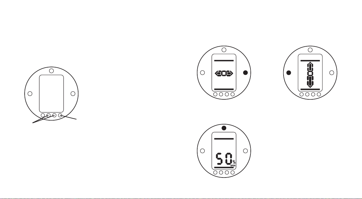
The liquid crystal display screen has 2
modes of position indication:
1. Valve position – power on
2. Valve position – power off
On power up the actuator’s liquid
crystal display screen is back-lit with a
“soft amber” light and one of the
indicator lamps will be on, dependent
on position. The display screen will
show percentage open or an end of
travel symbol. (See Figs 3.3, 3.4 and
3.5)
As standard, red lamp signifies valve
open, yellow intermediate, and green
lamp signifies valve closed. Open and
closed colour functions can be reversed
on request.
Open
Red indicator and open symbol
displayed
Fig. 3.3
Mid Travel
Yellow indicator and percentage open
value displayed
Fig. 3.4
Closed
Green indicator and closed symbol
displayed
Fig. 3.5
With the main power supply switched
off, the liquid crystal display screen is
powered by a battery and continues to
display actuator position. However, the
battery does not support screen backlighting, or position indicator lamps.
4
1
4
3
2
6
5
Page 9

3.4 Display–Alarm Indication
The IQT display incorporates valve,
control system, actuator and battery
alarm indication in the form of four
display icons. Located in the top portion
of the display, each icon represents
certain alarm conditions. Standard help
screens are also available to assist in
determining the actuator operational
and alarm status (refer to Help Screens
page 64).
Valve Alarm
Fig. 3.6
The valve alarm icon, Fig 3.6, is
displayed when a valve problem causes
the actuator to “trip-off’’ due to the
configured torque value being
developed (refer to [tC]/[tO] pages
20/21).The possible causes are:
•
Valve tight or obstructed in mid travel.
• Valve stuck or jammed
• Valve process conditions changed
(increase in pressure, flow etc.)
Once the actuator has tripped off on
torque, electrical operation in the same
direction is inhibited. The icon will
remain displayed until movement in the
opposite direction takes place.
The valve alarm icon will not be
displayed when stopping at end of
travel for valves configured to torque
seat or torque back seat at end of
travel (refer to [C2]/[C3] pages 18/19).
Tr y handwheel operation of the valve to
‘‘feel’’ for stiffness (refer to page 3).
Control Alarm
Fig. 3.7
The control system alarm icon, Fig 3.7,
is displayed when the remote control
system maintains an active ESD or
interlock signal (the ESD, interlock
function or conditional control having
been enabled.)
Local and Remote operation will be
inhibited while an active ESD or
interlock signal is present (refer to [A1]
ESD Action page 30, [A8] External
Interlocks page 32 and Conditional
Control [A9] page 32.)
Investigate the operational conditions
of the actuator remote control system.
5
Page 10

Actuator Alarm
Fig. 3.8
The actuator alarm icon, Fig. 3.8, is
displayed when an active actuator
alarm is present.
Electrical operation will be inhibited
while an alarm is present. The possible
causes are:
• Transformer thermostat tripped
• Battery low on power up*
• Power supply fault
*see Battery Alarm
(To identify the specific cause of the
alarm refer to Help Screens).
Battery Alarm
Fig. 3.9
The battery alarm icon, Fig. 3.9, is
displayed when the actuator detects its
battery as being low, discharged or
missing.
If, on power up, the actuator detects a
discharged battery and actuator power
loss inhibit feature [OS] is enabled
(refer to page 58), both battery and
actuator alarm icons (Fig.3.8 and 3.9)
will be displayed. Electrical operation
will be inhibited.
When the battery alarm icon
is displayed, the battery should be
replaced immediately (refer to page 62).
The actuator checks the battery status
at approximately 10 minute intervals.
After replacing a battery the alarm icon
will continue to be displayed until the
next check indicates the battery is
healthy. This may take up to 10
minutes.
6
Page 11

4.1 Bases F05 to F07
and FA05 to FA07
The base adaptor must be removed to
give access to the drive bush. Remove
the four capscrews and base adaptor as
shown in figure 4.
Fig. 4
Clear access to the drive bush is now
available as shown in figure 4. Using
the a 3mm allen key, unscrew the two
capscrews retaining the drive bush and
remove the drive bush from the
actuator.
Fig. 4.1
4.2 Bases F10 to F14
and FA10 to FA14
Removal of the drive bush does not
require the removal of the actuator
base. Using a 3mm allen key, unscrew
the two capscrews retaining the drive
bush.
Capscrews can be used to remove the
drive bush by screwing into the drive
bush as shown in figure 4.2.
Fig. 4.2
The range of IQT drive bushes is shown
in figure 4.3. Please refer to publication
E110E for maximum stem acceptance
details.
Fig. 4.3
4.3 Machining the Drive Bush
Once removed, the drive bush can be
machined to suit the valve stem. Ensure
machined position allows correct
orientation of actuator-to valve flange
and correct direction to close the valve.
4.4 Fitting the Drive Bush
Note: The drive bush can be fitted in
two possible positions, 180º apart. Fit
the drive bush into the centre column
ensuring that the stem orientation,
actuator position and direction of
operation are correct for valve
operation. Secure the drive bush with
the capscrews. For F05, FA05, F07 and
FA07 bases, refit the base adaptor and
secure with the four capscrews.
7
Preparing Drive Bush
4
Page 12

5.1 IQT Actuators
The IQT range of actuators are suitable
for part turn applications requiring up
to 60 starts per hour.
5.2 IQTM Actuators
The IQTM range of actuators are
suitable for modulating control duty of
up to 1200 starts per hour in
accordance with IEC 34-1 to S4 50%.
Commissioning of IQTM range
actuators is identical to the standard
IQT (refer to Sections 7, 8 and 9).
5.3 IQTF Actuators
The IQTF range of actuators are
suitable for part-turn and multi-turn,
non-thrust applications requiring low
speed and low operating turns.
Commissioning of IQTF range actuators
is similar to the standard IQT (refer to
Sections 7, 8 and 9).
5.4 Lifting the Actuator
(Refer to Weights and Measures page
71 for actuator weight.)
Ensure the valve is secure before fitting
the actuator, as the combination may
be top heavy and therefore unstable.
If it is necessary to lift the actuator
using mechanical lifting equipment
certified slings should be attached as
indicated in Figure 5. At all times
trained and experienced personnel
should ensure safe lifting, particularly
when mounting actuators.
A suitable mounting flange conforming
to ISO 5210 or USA Standard MSS
SP101 must be fitted to the valve.
Actuator to valve fixing must conform
to; Material Specification ISO Class 8.8,
yield strength 628 N/sq mm.
WARNING:
Do not lift the actuator and valve
combination via the actuator. Always
lift the valve/actuator assembly via the
valve.
Fig. 5
WARNING:
The actuator should be fully supported
until full valve stem engagement is
achieved and the actuator is secured to
the valve flange.
Fig. 5.1
5.5 Securing Actuator to Valve
Before engagement ensure that the
actuator and valve are in the same
position (i.e. closed) and the drive bushmachining matches the stem position.
Actuator position can be determined
using the display (refer to section 3.3
page 4) and if necessary can be moved
using the handwheel (refer to section
3.1 page 3). It may be necessary to
adjust the stop bolts to enable
sufficient travel. Refer to section 5.6
page 9.
8
Mounting the Actuator
5
Page 13

Secure actuator to valve with four fixing
bolts. Check that the cast groove in
actuator base is not obstructed see Fig
5.1. Its purpose is to protect the
actuator in the event of a product leak
from the valve stem/gland packing.
Check base fixing bolts are tight.
5.6 Stop Bolts
It is recommended that stop bolt
adjustment be carried out by the
valvemaker/supplier before the valve is
fitted into pipework. Once installed, the
valve maker/supplier should be
consulted before stop bolt readjustment is carried out. Stop bolts
can be wired to prevent tampering.
After setting or adjustment of stop
bolts the actuator limits must be reset,
refer to Limits LC, LO page 22.
The IQT stop bolts are located below
the terminal compartment. Stop bolt
adjustment allows +/- 5º variation of
travel at each end position. Screwing
bolts in reduces movement, out
increases movement. For clockwise
closing valves the right hand bolt is the
closed stop as shown with spanner in
fig 5.2. The left is the open stop. Stop
bolts are factory set to give a nominal
90º travel.
Fig. 5.2
Stop Bolt sizes.
IQT 125 to 500: M12 bolt requiring
19mm AF spanner.
IQT1000 & 2000: M20 bolt requiring
30mm AF spanner.
Adjustment for non seating
valves types
For closed and open stop position
adjustment:
Undo stop bolt lock-nut. Move actuator
and valve to the required stopping
position (it may be necessary to
unscrew stop bolt to allow more travel).
Screw stop bolt in until a stop is felt.
Tighten stop bolt lock nut.
Adjustment for seating valves
types
For closed and open stop position
adjustment:
Undo stop bolt lock-nut. Move actuator
and valve to the required seating
position of the valve (it may be
necessary to unscrew stop bolt to allow
more travel). Screw stop bolt in until a
stop is felt and then back off by 3
turns. Tighten stop bolt lock-nut.
Reset actuator limits
Refer to Limits LC, LO page 22.
9
Page 14

Ensure all power supplies are
isolated before removing
actuator covers.
Check that the supply voltage agrees
with that stamped on actuator
nameplate.
A switch or circuit breaker must be
included in the wiring installation of the
actuator. The switch or circuit breaker
shall be mounted as close to the
actuator as possible and shall be
marked to indicate that it is the
disconnecting device for that particular
actuator. The actuator must be
protected with overcurrent protection
devices rated in accordance with Rotork
publication No. E135E Electric motor
performance data for IQT range
actuators.
WARNING:
Actuators for use on phase to
phase voltages greater than 600V
a.c.must not be used on supply
systems such as floating, or
earth-phase systems, where
phase to earth voltages in excess
of 600V a.c. could exist.
6.1 Earth/Ground Connections
A lug with a 6mm diameter hole is cast
adjacent to the conduit entries for
attachment of an external protective
earthing strap by a nut and bolt. An
internal earth terminal is also provided,
however it must not be used alone as
the protective Earth Connection.
6.2 Removing Terminal Cover
Using a 6mm Allen key loosen the four
captive screws evenly. Do not attempt
to lever off the cover with a screwdriver
as this will damage the “O” ring seal
and may damage the flamepath on a
certified unit.
Actuators containing a Setting Tool
fitted to the inside of the terminal
compartment cover are identified with
a self-adhesive yellow label on the
outside of the terminal compartment
cover.
The wiring code card fixed in the cover
is particular to each actuator and must
not be interchanged with any other
actuator. If in doubt check the serial
number on the code card with that of
the actuator.
Fig. 6
A plastic bag in the terminal
compartment contains: Terminal screws
and washers, spare cover “O” ring
seal,wiring diagram and instruction
book.
6.3 Cable Entry
Only appropriate certified ExplosionProof entry reducers, glands or conduit
may be used in hazardous locations.
Remove red plastic transit plugs. Make
cable entries appropriate to the cable
type and size. Ensure that threaded
adaptors, cable glands or conduit are
tight and fully waterproof. Seal unused
cable entries with a steel or brass
threaded plug. In hazardous areas an
appropriately certified threaded
blanking plug must be used.
6.4 Connecting to Terminals
On EExde enclosure units connections
to the power and control terminals
must be made using AMP type 160292
ring tabs for power and earth terminals
and AMP type 34148 ring tabs for the
control terminals.
Refer to the wiring diagram inside the
terminal cover to identify functions of
terminals. Check that supply voltage is
the same as that marked on the
actuator nameplate.
Remove power terminal screen.
Begin by connecting these cables and
replace screen.
When all connections are made ensure
wiring diagram is replaced in the
terminal compartment.
6.5 Replacing Terminal Cover
Ensure cover “O” ring seal and spigot
joint are in good condition and lightly
greased before re-fitting cover.
10
Cable Connections
6
Page 15

7.1 The Setting Procedure
The Rotork IQ range of actuators is the
first that enables commissioning to be
carried out without removing covers.
Setting torque, limit and other
functions is achieved by using the InfraRed Setting Tool. The Setting Tool is
certified Intrinsically Safe to allow
commissioning in hazardous areas.
All the commissioning functions are
stored in non-volatile memory in the
actuator. The Setting Tool enables the
user to view all the functions in turn via
the actuator display window. As each
function is viewed its setting can be
checked and, if required, changed
within the bounds of that function.
Commissioning may be carried out with
main power switched on or off. Refer
to page 15 for Power Off Setting.
The setting procedure is divided into
two stages:
1. Primary Functions
Settings for end of travel limit
actions, torque values, limit
positions etc.
2. Secondary Functions
Settings covering the control,
indication and optional
equipment functions.
All IQT actuator functions are
configured before dispatch to
Rotork standard default settings
unless alternatives have been
specified with the order. Should
difficulty be encountered during
commissioning the default
settings can be reinstated,
returning the actuator
configuration to its original
manufactured state. Site
commissioning can then begin
again
(refer to Section 9.17).
The default function should be used
with caution as settings selected after
manufacture may be essential for the
safe operation of the valve and/or
plant.
Actuator Display
11
Commissioning
7
Position Display 50 This may be an open or closed symbol
or a percentage open value.
Q
To rque and Position Refer to Section 10.
Q
Password P?
O
PC
O
Ir
O
Ic
Q
Setting Branch cr
O
(crossroad)
Q
Primary Functions Secondary Functions
Direction Indication Contacts
Limit Actions Control Mode
To rque Values Options
Limit Positions Help Screens
Defaults
Note: The Primary Functions
must be commissioned first.
Page 16

7.2 The Setting Tool
Specification
Enclosure IP67
Certification EEx ia IIC T4 (intrinsically safe)
FM, INT SAFE, Class I & II Div 1 Groups A B C D E F G, T4A
CSA, Exia, Class I, II Div 1 Groups A B C D
Power supply 9V Battery (supplied and fitted)
Operating range 0.75m (from actuator display window)
Name Instruction
1. Q Key* Display next function down
2.
O
Key* Display next function across
3.
-
Key Decrease/change displayed function’s value or option setting
4.
+
Key Increase/change displayed function’s value or option setting
5. Key Enter displayed value or option setting
* Pressing the two arrow keys together returns the actuator display to the position
indication mode
Infra-red local operation (when enabled)
5. Key Stop actuator
6. Key Open actuator
7. Key Close actuator
8. Infra-red Transmitter Window
Fig. 7 The Setting Tool
Setting Tool Battery Replacement
Battery status can be checked by looking at the Infra-red transmitter window while
depressing any Setting Tool button. A flashing red indicator should be seen.
Battery replacement must be carried out in a safe area. To replace the battery
remove the six caphead screws in the back of the Setting Tool. Remove the back
cover to expose the battery.
In order to maintain hazardous area certification fit only Duracell MN1604 or
Rayovac Alkaline Maximum NoAL-9V battery types. Refit cover ensuring red
indicator LED faces the transmitter window in the back cover.
When a button is depressed the Setting Tool transmits the relevant instruction to
the actuator by infra-red pulses and must therefore be directly in front of the
actuator indicator window and at a distance no greater than 0.75m.
12
8
2
4
6
7
5
3
1
Page 17

7.3 Entering the Actuator
Setting Procedure
With the actuator securely mounted on
the valve, the mains supply on and
Local control or Stop selected.
PRESS THE Q KEY.
The actuator display will change and
the Torque & Position display will be
seen. (For instantaneous torque &
position monitoring, refer to Section
10, page 62.)
PRESS THE Q KEY.
The actuator display will change and
the password protection display will
be seen.
The Actuator Function Settings
can be protected by the Use
of a Password
7.4 Setting Mode – Password
To enable setting and adjustment of the
actuator functions the correct password
must be entered. The factory set (default)
password is [ld]. If the actuator has
previously been set with a site password
this must be displayed.
Use the
+
or -keys to scroll through the
available passwords 00–FF (hexadecimal).
With the correct password displayed press
the enter key.
PRESS THE KEY
.
Two “setting” bars will appear and will
remain visible on every function display
screen.
Default Password,
Setting Mode Enabled
7.5 New Password [PC]
To configure a new password, the
actuator must be in setting mode with
the password display – setting mode
enabled – showing,
PRESS THE OKEY.
The display will change to [PC]. Using the
+
or -key scroll through the available
passwords until the desired password is
displayed.
PRESS THE KEY.
Password Changed to [IE]
NOTE: The new password becomes
effective the next time setting mode is
entered.
7.6 Checking Mode
The actuator function settings can be
checked without entering the correct
password. The settings can only be
viewed and not altered. The setting bars
will not be seen.
Password Display, Checking Mode
Once the procedure has been entered in
the required mode
PRESS THE Q KEY.
The procedure branch [Cr] (crossroad)
display
can now be seen (refer to Section
7.7 page 14).
13
Page 18

7.7 Procedure Branch –
Crossroad [Cr]
To access the Primary Function settings
press the arrow Q key (refer to
Section 8 Commissioning Primary
Functions page 15).
To access the Secondary Function
settings press the arrow
O
key (refer
to Section 9 Commissioning Secondary
Functions page 25).
7.8 The Actuator Display –
Setting/Checking Mode
Actuator functions as laid out in the
Primary and Secondary commissioning
stages, can be individually displayed by
using the Setting Tool arrow keys.
The
Q arrow key will always display
the FIRST function on the next level
DOWN within the procedure.
The
O
arrow key will always display
the NEXT function on the SAME level
and will wrap around the functions on
the same level.
The actuator display indicator lamps will
continue to indicate valve position.
Actuator functions are displayed in
code form in the top portion of the
liquid crystal display screen.
The setting for the displayed function is
shown in the lower portion of the
screen. Depending on the actuator
function displayed, its setting may be
an option or a value. In setting mode
the Setting
Tool
+
or
-
keys will cause the setting
to be changed. In checking mode the
settings cannot be altered.
In setting mode, once displayed, a new
setting can be entered into the actuator
memory by pressing the key.
The setting will flash off and back on,
confirming its selection.
TOP PORTION
Function e.g.
tC = Torque Close
LOWER PORTION
Function Setting
e.g. Value = 40%
Typical Actuator Function Display
Setting Mode Enabled
7.9 Returning to
Valve Position Display
There are four ways of returning to
valve position display:
1. Approximately 5 minutes after the
last Setting Tool operation the
display will automatically return to
position display.
2. Press the
Q and
O
arrow keys
together.
3. Press the Q arrow key until the
display returns to position.
4. With any actuator function screen
displayed, select Remote control
using the red Local/Stop/Remote
selector.
14
Page 19

Fig. 8
The actuator’s Primary Function settings
affect the correct operation of the valve
by the actuator. If the actuator has
been supplied with the valve, the valve
maker or supplier may have already
made these settings.
ELECTRICAL OPERATION MUST NOT
TAKE PLACE UNTIL THE PRIMARY
SETTINGS HAVE BEEN MADE AND
CHECKED.
This instruction assumes setting mode
has been entered (refer to section 7.4
page 13).
Viewing the Primary
Function Settings
With the actuator mounted on the
valve, the power supply on and Local or
Stop control selected, point the Setting
Tool at the actuator indicator window
from a distance of no more than
0.75m. By pressing the Q key and,
when appropriate, the Okey, it is
possible to move through the
procedure, displaying the various
functions and their settings as shown in
Fig. 8.1 (refer to page 16).The righthand side of Fig.8.1 explains the
function of each LCD display.
Power Off Setting
IQT allows settings to be viewed and
set without main power. To enable this
function, engage handwheel drive and
rotate until the output drive moves
(refer to page 3). The Setting Tool can
now be used. As long as a Setting Tool
key press takes place within the 30
seconds timeout period, Power Off
Setting will remain enabled. If no infrared Setting Tool communication takes
place the display will return to
indicating position. The actuator must
then be operated by handwheel to
re-enable Power Off Setting.
Settings and operation must be
verified by electric operation and
function test of the actuator to
ensure correct operation.
15
8
Commissioning –
Primary Functions
Page 20

Viewing the Primary Function Settings
Position Display
50
(This may be an open or closed symbol or a % open value.)
Refer to Section 7
QQ
Commissioning
To rque and Position Display
QQ
P? OPC OIr OIc Password
O
Password ChangeOIrDAOCell Phone
QQ
cr Procedure Branch (crossroad)
QQ
c1 Oc2 Oc3 Direction to Close
O
Close ActionOOpen Action
QQ
tC OtO To r que Value Closing
O
To rque Value Opening
QQ
LC OLO Limit Closed
O
Limit Open
QQ
50 Position Display
Fig. 8.1 Primary Setting Function Displays
16
PRIMARY FUNCTIONS CONTENTS
page
C1 Direction to Close 17
C2 Close Action 18
C3 Open Action 19
tC Torque Value Closing 20
tO Torque Value Opening 21
LC Set Limit Closed 22
LO Set Limit Open 22
AA Actuator Speed Setting 23
The actuator can be configured to be clockwise or anti-clockwise to close.
Page 21

Manually operate actuator and valve to
establish correct closing direction. If the
handwheel labelling is found to be
incorrect please apply to Rotork for
conversion labels.
50
Q
Q
P? OPC OIr OIc
Q
cr
Q
c1 Oc2 Oc3
Q
tC OtO
Q
LC OLO
Q
50
Using the +or -key, display character
conforming to correct closing direction.
[C] in the Setting Field Indicating
Clockwise to Close
[A] in the Setting Field Indicating
Anti-clockwise to Close
Having ensured that the display
corresponds to the established
closing direction
PRESS THE KEY.
The displayed option will flash,
indicating that it has been set.
PRESS THE OKEY.
17
Direction to Close
C1
Page 22

IQT actuators are designed to stop at
the end of travel by torque limitation
against the actuator stop bolts. Stop
bolts should therefore be set to the
precise stopping position required, refer
to section 5.6.
IQTF actuators can be configured to
close on torque or limit. Refer to valve
manufacturers instructions.
50
Q
Q
P? OPC OIr OIc
Q
cr
Q
c1 Oc2 Oc3
Q
tC OtO
Q
LC OLO
Q
50
Using the +or -key, display the
desired option.
[Ct] in the Setting Field Indicating
Close on Torque - defualt setting.
[CL] in the Setting Field Indicating
Close on Limit
Having selected the required option
PRESS THE KEY.
The displayed option will flash,
indicating that it has been set.
PRESS THE OKEY.
NOTE:
When set to close on torque,
the actuator will apply the value of
torque as set for [tC] in seating the
valve (refer to [tC] page 20).
18
Close Action
C2
Page 23

IQT actuators are designed to stop at
the end of travel by torque limitation
against the actuator stop bolts. Stop
bolts should therefore be set to the
precise stopping position required, refer
to section 5.6.
IQTF actuators can be configured to
close on torque or limit. Refer to valve
manufacturers instructions.
50
Q
Q
P? OPC OIr OIc
Q
cr
Q
c1 Oc2 Oc3
Q
tC OtO
Q
LC OLO
Q
50
Using the +or -key display the desired
option.
[Ot] in the Setting Field Indicates
Open on Torque - defualt setting.
[OL] in the Setting Field Indicates
Open on Limit
PRESS THE KEY.
The displayed option will flash,
indicating that it has been set.
PRESS THE OKEY.
NOTE:
When set to open on torque,
the actuator will apply the value of
torque as set for [tO] in back seating
the valve (refer to [tO] page 21).
19
Open Action
C3
Page 24

The value of torque available in the
close direction can be configured. Refer
to valve manufacturer for
recommended value.
The closing torque value can be varied
between 40% and Rated, in 1%
increments.
50
Q
Q
P? OPC OIr OIc
Q
cr
Q
c1 Oc2 Oc3
Q
tC OtO
Q
LC OLO
Q
50
Using the +and -keys display
recommended value. In the absence of
a recommended torque value, try a low
setting and increase until satisfactory
valve operation is achieved.
PRESS THE KEY.
The displayed value will flash, indicating
that it has been set.
Should the set value of torque be
developed in closing, the actuator will
torque trip and stop.
PRESS THE OKEY.
NOTE: Rated torque is quoted on the
actuator nameplate.
40% of Rated Torque
99% of Rated Torque
Rated Torque
20
To rque Value Closing
tC
Page 25

The value of torque available in the
open direction can be configured. Refer
to valve manufacturer for
recommended value.
50
Q
Q
P? OPC OIr OIc
Q
cr
Q
c1 Oc2 Oc3
Q
tC OtO
Q
LC OLO
Q
50
The opening torque value can be varied
between 40% and Rated, in 1%
increments. In addition “Boost” can be
configured when no open torque
protection is required.
BOOST SHOULD NOT BE
SELECTED WHEN THE ACTUATOR
HAS BEEN CONFIGURED TO OPEN
ON TORQUE (refer to [C3] page 19)
unless back seating at Rated torque is
acceptable.
Using the
+
and -keys display the
recommended torque value.
In the absence of a recommended
torque value, try a low setting and
increase until satisfactory valve
operation is achieved.
NOTE: Rated torque is quoted on the
actuator nameplate. Boost torque is at
least 140% of Rated torque.
PRESS THE KEY.
The displayed value will flash, indicating
that it has been set.
Should the set value of torque be
developed in opening, the actuator will
torque trip and stop.
PRESS THE Q KEY.
40%
99%
Rated
Boost
In checking mode, on pressing the
Q
key after reviewing open torque setting,
the display will revert to valve position.
21
To rque Valve Opening
tO
Page 26

NOTE: It is possible to set the Open
Limit Position [LO] first.
50
Q
Q
P? OPC OIr OIc
Q
cr
Q
c1 Oc2 Oc3
Q
tC OtO
Q
LC OLO
Q
50
NOTE:
When in checking mode Set
Limit Closed [LC] does not appear.
With [LC] displayed
Limit Closed
Move valve manually to the closed
position. Allow for overrun by winding
actuator output open by two
handwheel turns.
PRESS THE KEY.
The two bars will flash and the closed
indicator lamp will illuminate, indicating
closed limit position has been set.
PRESS THE OKEY.
To check closed limit position hand
wind valve open until the amber lamp
illuminates. Wind valve back closed
until the closed lamp illuminates.
50
Q
Q
P? OPC OIr OIc
Q
cr
Q
c1 Oc2 Oc3
Q
tC OtO
Q
LC OLO
Q
50
NOTE:
When in checking mode Set
Limit Open [LO] does not appear.
With [LO] displayed
Limit Open
Move valve manually to the open
position. Allow for overrun by winding
actuator output closed by two
handwheel turns.
PRESS THE KEY.
The two bars will flash and the open
indicator lamp will illuminate, indicating
open limit position has been set.
PRESS THE Q KEY.
The open symbol (refer to Fig. 3.3.
page 4) should now appear.
22
Set Limit Closed
LC
Set Limit Open
LO
Page 27

With [AA] displayed
Use the
+
and -key to select the
required actuator operating time. The
settings are displayed in hexadecimal
and can be related to the actuator
speed as shown in Fig 8.2.
PRESS THE KEY.
The displayed value will flash, indicating
that it has been set.
All speed settings are adjustable in unit
increments of hexadecimal. Any value
of hex outside of the range stated will
not be accepted into the actuator
memory.
% Speed Hex Setting
25 19
30 1E
35 23
40 28
45 2D
50 32
55 37
60 3C
65 41
70 46
75 4B
80 50
85 55
90 5A
95 5F
100 64
Fig 8.2
NOTE: Mains power has to be on
for speed setting to be carried out.
23
Speed Setting
AA
Positional Display
Q
Q
P?
OPCOIrO
Ic
Q
Contact Function
cr
O
Contact S1
r1
Q
Contact S2
r2
Q
Contact S3
r3
Q
Contact S4
r4
Q
ESD Action
Control Mode
Configuration
A1
Q
Extra Indication Folomatic Remote Bus
Contacts CPT
Remote Control Control Source
System
Option Selection OE O OI O OF O Od O OP
[On]
Q
PA
Q
50
IQT operating time can be adjusted
between 25% and 100% of the
maximum time (50% and 100% for
IQT2000). IQT are factory set at the
maximum speed. IQTM actuators are
dispatched with the minimum speed set.
To access speed setting [AA] screen, bus
system [OP] has to be set to [O
n], using
the +and -key.
After this setting, proceed to screen [AA].
IrDA
comms
Primary
Functions
IQT Speed
Setting
AA
Q
Cell
Phone
Page 28

50
Q
Q
P? OPC OIr OIc
Q
cr
Q
c1 Oc2 Oc3
Q
tC OtO
Q
LC OLO
Q
50
If the procedure has been followed as
described, the positional display will
indicate that the actuator is in the open
position.
Select Remote control momentarily,
using the red selector to exit setting
procedure and then select required
control: Local, Stop or Remote.
With the correct settings made electric
operation can now be carried out
safely.
24
Return to
Positional Display
Page 29

Fig. 9
The Secondary Functions can be
configured to suit site control and
indication requirements. It is important
that Primary Functions such as limits
and torque switch settings are set
before work commences on
commissioning the Secondary
Functions. The layout of the Secondary
Functions accessed with the Setting
Tool are detailed in Fig. 9.1. To
successfully commission the Secondary
Functions, information about the site or
process control system will be required.
The supplied actuator Wiring Diagram
details control and indication devices
fitted to the actuator along with
terminal connection detail and standard
remote control wiring systems.
Power Off Setting
IQT allows settings to be viewed and
set without main power. To enable this
function, engage handwheel drive and
rotate until the output drive moves by
one turn (refer to section 3).The
Setting Tool can now be used. As long
as a Setting Tool key press takes place
within the 30 seconds timeout period,
Power Off Setting will remain enabled.
If no infra-red Setting Tool
communication takes place the display
will return to indicating position. The
actuator must then be operated by
handwheel to re-enable Power Off
Setting.
Settings and operation must be
verified by electric operation and
function test of the actuator to
ensure correct operation.
25
9
Commissioning –
Secondary Functions
Page 30

26
Positional Display
Q
Q
P?
OPCOIrO
Ic
Q
Contact Function
Value Contact Form
cr
O
Contact S1
r1
O
r1
O
r1
Q
Contact S2
r2
O
r2
O
r2
Q
Contact S3
r3
O
r3
O
r3
Q
Contact S4
r4
O
r4
O
r4
Q
ESD ESD Thermostat ESD Overide ESD Override Maintained 2-wire External Conditional Torque Switch
ESD Action Contact Type Bypass Interlocks Local Stop Local Control Control Interlocks Control Bypass
Control Mode
Configuration
A1 O A2 O A3 O A4 O A5 O A6 O A7 O A8 O A9 O At
Q
Extra Indication Folomatic Remote Bus Interrupter Setting Tool Power Loss
Contacts CPT
Remote Control Control Source
System Timer Local Control Inhibit
Option Selection OE O OI O OF O Od O OP O OJ O Or O OS
Q
Option Functions - If OE, OF, OP, or OJ are fitted and selected “ON” their appropriate set-up screens will be inserted here.
Q
Help Screens H1 O H2 O H3 O H4 O H5 O H6 O H7 O H8 O H9
Q
Default Option d1 O d2
Q
Return to Positional Display Fig. 9.1 Secondary Functions
50
IrDA
comms
Primary
Functions
Q
Cell
Phone
Page 31

Having established that the Primary
Functions have been correctly set, the
Secondary Functions can now be
configured to suit site control and
indication requirements.
It is possible to move through the
various Secondary Functions as shown
in Fig. 9.1 using the
O
and Q keys.
The actuator wiring diagram will
indicate any options fitted.
Options Setting Tool Local Control [Or]
and Power Loss Inhibit [OS] are
standard features, their use being
optional.
In order to display the Secondary
Functions it is necessary to press the
Qkey until [Cr] appears.
If you have chosen to enter Secondary
Functions in the checking mode the
display will be as Fig. 9.2.
If you have chosen to enter Secondary
Functions in the setting mode the
display will be as Fig. 9.3 (refer to
Section 7).
Fig. 9.2 Fig. 9.3
PRESS THE O KEY.
27
9.1
SECONDARY FUNCTIONS CONTENTS
page
9.0 Commissioning Secondary Functions 25
9.1 Accessing the Secondary Settings 27
9.2 Indication Contacts S1, S2, S3 and S4 28
9.3 Control Mode Configuration 30
9.4 Option Extra Indication Contacts S5–S8 33
9.5 Option CPT (Current Position Transmitter) 34
9.6 Option Folomatic Remote Control 35
9.7 Remote Control Source 38
9.8 Bus System Option Pakscan 39
9.9 Bus System Option Modbus 43
9.10 Bus System Option Profibus DP 47
9.11 Bus System Option DeviceNet 51
9.12 Bus System Positioning Control Settings 54
9.13 Option Interrupter Timer 56
9.14 Setting Tool Local Control 58
9.15 Inhibit Operation After Power Loss 58
9.16 Actuator Type Setting 59
9.17 Default Options 60
9.18 Default Options 61
10.0 Maintenance,Monitoring and Troubleshooting 62
10.1 Help Screens 64
10.2 IrDA Diagnostics and Configuration 69
Accessing the
Secondary Functions
Page 32

Contact S1 - Function
r1
Contact S1 - Value
r1
Indication contacts S1 [r1], S2 [r2], S3
[r3] and S4 [r4] may each be set to trip
for any one of the following functions:
Code Function
[CL] closed end position
[OP] open end position
[Po] intermediate position
[tC] torque trip close
[tO] torque trip open
[tt] torque trip any position
[tl] torque trip mid travel
[dC] actuator closing
[dO] actuator opening
[d?] actuator rotating
[St] motor stalled
[bA] battery low
[HA] hand operation
[bL] blinker
[LS] local stop
[Ol] open interlock
[Cl] close interlock
[lL] interlock active
[ES] ESD signal
[LP] lost phase
[Lo] local selected
[
rE] remote selected
[AA] actuator alarm *
[24] 24V power failure
[
rr] motor running
[UA] Valve alarm*
[Ht] thermostat tripped
[CA] Control alarm*
[
rP] relay parity
The S contact form can be set normally
open [no] or normally closed [nc].
The procedures for setting up contacts
S2, S3 and S4 are the same as those
shown for S1.
Unless specified with order, the
default settings for indication
contacts are as follows:
S1 – [CL] closed end position [no]
S2 – [OP] open end position [no]
S3 – [CL] closed end position [nc]
S4 . [OP] open end position [nc]
* Contact alarm indication will operate
under the same conditions as the
display alarm indication icons (refer to
page 5 for information).
Using the
+
or -key display the desired
function.
PRESS THE KEY.
The displayed function will flash
indicating that it has been set.
Contact S1 Configured to Trip
at Valve Closed Limit
PRESS THE O KEY.
When the S contact function is set to
[P0], the required intermediate position
value must be set.
No other contact function requires
a value to be set.
The value can be set from 1% open to
99% open in 1% increments.
Using the
+
or -key, display the
required value.
PRESS THE KEY.
The displayed value will flash indicating
that it has been set.
Value Set to Indicate
25% Open
PRESS THE O KEY.
28
9.2
Indication Contacts
S1, S2, S3 and S4
Page 33

Use the +or -keys to select between
[nO] (normally open) and [nC]
(normally closed).
PRESS THE KEY.
The displayed option will flash
indicating that it has been set.
Contact S1 Configured as a
Normally Open Contact
NOTE: If function [PO] is selected and
it is configured as a normally open
contact it will make at the set value
with the actuator moving in the open
direction.
To access S2–S4
PRESS THE Q KEY.
(Refer to Fig 9.1)
29
r1
Contact S1
Contact Form
Page 34

The Control Mode Configuration affects
how the actuator will respond under
conditions of emergency shut down,
local control, remote control interlocks,
and 2-wire remote control. Also
included is an unseating torque switch
bypass function. Unless specified with
order, the control mode configuration
will be set as shown for default
configuration on page 60.
If it is necessary to change the
configuration follow the instructions in
this section.
There are 10 configurable control
functions:
A1 ESD action
A2 ESD contact type
A3 ESD thermostat bypass
A4 ESD override interlock
A5 ESD override local stop
A6 Maintained local control
A7 2-wire remote control
A8 External interlocks
A9 Conditional Control
At Torque switch bypass.
An active ESD signal applied to the
actuator will override any existing or
applied local or remote control signal.
ESD can be configured to override the
transformer thermostat, active
interlocks or local stop selection. Refer
to A3, A4 and A5.
The default action under an active ESD
signal is to stay put [SP].
Press the
+
or -key to select the
required ESD action:
[CL] Close on ESD
[SP] Stay put on ESD
[OP] Open on ESD
PRESS THE KEY.
The displayed option will flash
indicating that it has been set.
ESD Set to Close
The default setting for ESD Contact
Type is [
nO].
The actuator responds to a remote
control ESD signal derived from a
normally open contact making. For ESD,
where a remote control ESD signal is
derived from a normally closed contact
breaking, the signal being removed,
press the
+
or -key.
The display will change to [
nC].
PRESS THE KEY.
The displayed option will flash
indicating that it has been set.
Actuator Responds to a Remote,
Normally Open ESD Contact
Making (Signal Applied)
Note: If Folomatic analogue control is
required A2 must be set to [
nO].
The default setting for Thermostat
Bypass is [OF] during ESD. The
thermostats remain in circuit and
enabled during ESD.
The thermostats can be bypassed
during ESD as a factory set, hard-wired
option only. Contact Rotork for
information.
Danger: Actuator hazardous area
certification is invalidated while
the thermostats are bypassed.
A3 should be set to reflect the factory
set configuration of thermostat bypass.
During an ESD event:
[A3]=[OF] thermostats enabled
[A3]=[O
n] thermostats bypassed
Thermostats Enabled During ESD
30
9.3
ESD Action
A1
ESD Contact Type
A2 A3
Control Mode
Configuration
ESD Thermostat
Bypass
Page 35

The default setting for ESD Override
Interlocks is [OF]. ESD action will not
override an active interlock applied to
the actuator.
If an applied ESD signal is required to
override active interlocks causing the
ESD action as set for A1, press the
+
or
-
key. The display will change to [On].
PRESS THE KEY.
The displayed option will flash
indicating that it has been set.
ESD Override Interlock – Off
The default setting for ESD Override
Local Stop is [OF]. ESD will not override
local stop when selected.
If an applied ESD signal is required to
override local stop causing the ESD
action as set for A1, press the
+
or
-
key. The display will change to [On].
PRESS THE KEY.
The displayed option will flash
indicating that it has been set.
ESD Override Local Stop – Off
The default setting for Local Actuator
Pushbutton control is self-maintained
[O
n].
If non-maintained actuator pushbutton
control is required (jogging, inching,
push to run), press the
+
or -key. The
display will change to [OF].
PRESS THE KEY.
The displayed option will flash
indicating that it has been set.
Self-Maintained Local Control
The default setting for 2-wire Remote
Control is Stayput [SP]. If a open and
closed remote control signal are applied
simultaneously the actuator will stayput
(stop if running). Refer to actuator
wiring diagram or publication E120E.
Use the
+
or -key to select the
required priority:
[OP] Open
[SP] Stay put
[CL] Close
PRESS THE KEY.
The displayed option will flash
indicating that it has been set.
2-wire Control – Stayput Priority
31
A4
ESD Override
Interlocks
A5
ESD Override
Local Stop
A6
Maintained
Local Control
A7
2-wire Remote
Control
Page 36

Actuators are delivered with the
interlock facility disabled [OF] Refer to
the actuator wiring diagram or
publication E120E for interlock control
circuits.
To enable remote external interlocks
press the
+
or -key.
The display will change to [O
n].
PRESS THE KEY.
The displayed option will flash
indicating that it has been set.
Interlocks Disabled
Note: If interlocking is required in only
one direction, it will be necessary to
connect a link between the actuator
terminals associated with the other
direction.
Where a high level of safety integrity is
required, Conditional Control can be
configured. In this mode two discreet
signals are required for remote
operation. Remote control will be
conditional on both a control signal
(open or close) and the appropriate
interlock signal being applied
simultaneously. Failure of either or a
spurious signal will not cause operation.
Interlocks [A8] must be set [O
n].
Interlock signals are not required for
local operation.
The default setting for conditional
control is [OF]. To enable conditional
control press the
+
or -key.The display
will change to [On].
PRESS THE KEY.
The displayed option will flash
indicating that it has been set.
Conditional Control Off
The default setting for Torque Switch
Bypass is [OF], the torque switches are
not bypassed during the unseating
movement.
To bypass the torque switches during
the unseating movement press the
+
or
-
key.
The display will change to [O
n].
PRESS THE KEY.
The displayed option will flash
indicating that it has been set.
The torque switches will be bypassed
from closed limit to 5% open when
opening and from open limit to 95%
when closing. Bypassing the torque
switches makes torque in excess of
rated and up to actuator stall available
for unseating a ‘‘sticky’’ valve. Outside
these positions the torque setting will
revert to the values set for [tC], see
page 20 and [tO] page 21.
Torque Switch Bypass Off
32
External Interlocks
A8
Conditional Control
A9
To rque Switch Bypass
At
Page 37

Extra indication contacts S5 [r5], S6
[r6], S7 [r7] and S8 [r8] are available as
an option.
Check actuator circuit diagram for
inclusion.
When the Extra Contact Option is
included the set-up procedure and
available contact functions for S5 – S8
are identical to S1–S4 (refer to Section
9.2 page 28).
Unless specified with order the default
setting for the extra indication contacts
will be as follows:
S5 [r5] Close limit indication
S6 [r6] Open limit indication
S7 [r7] To r que trip mid travel
S8 [r8] Remote control selected
NOTE: If the Extra Contact Option is
not included in the actuator build, any
settings made for S5–S8 will have no
effect on the indication output of the
actuator.
The action of turning on the Extra
Contact Option makes an additional
series of set-up screens available
Enabled Disabled
Extra Contact Set-up Displays
Press the
+
or -key to select the Extra
Contact Option set-up screens [O
n].
PRESS THE KEY.
The displayed option will flash
indicating that it has been set.
PRESS THE Q KEY TO ACCESS S5
TO S8 SET-UP DISPLAYS.
The procedure for setting S5 to S8
is the same as that for S1 to S4
(refer to Section 9.2 page 28).
33
9.4
Option Extra
Indication Contacts
OE
Display Extra Contact
Set-up Screens
Page 38

Setting instructions for actuators
including a CPT providing 4-20
mA analogue position feedback.
The CPT is an optional extra. It may be
internally or externally powered.
Check wiring diagram for inclusion and
connection details.
With [HI] Displayed, the (CPT)
20mA Output will Correspond to
Actuator Fully Open
If 20mA is required to correspond to
actuator closed use the
+
or -key to
change to [LO].
PRESS THE KEY.
The displayed option will flash
indicating that the option has been set.
NOTE: If the actuator has options
Folomatic and CPT, redefining the CPT,
will require the Folomatic to be
recommissioned (refer to Section 9.6
Folomatic [OI] page 35).
34
9.5
Option CPT [OI]
(Current Position Transmitter)
Page 39

Setting instructions for actuators
including a Folomatic
(proportional) Controller for use
in (analogue) valve position
control.
The Folomatic is an optional
control device. Check actuator
wiring diagram for inclusion.
Before setting the parameters for
Option Folomatic ensure Remote
Control Source [Od] has been
selected to [bo] in Section 9.7.
Folomatic set-up screens can be turned
OFF to provide extra security.
Once selected ON the option function
displays allow commissioning of the
Folomatic to be undertaken.
NOTE: Tu rning ON/OFF the Folomatic
set-up screens (when fitted) does not
affect its operation.
This instruction lists the Folomatic
function displays in their sequence and
assumes that all Folomatic functions are
to be checked/set.
The actuator should be selected in Local
or Stop with the set point signal
connected to terminals 26(+ve) and
27(-ve) (refer to wiring diagram).
Before commissioning of the Folomatic
functions can begin, the Folomatic
Feedback must be set to suit the
applied set point signal.
With [HI] displayed, an increasing set
point signal will correspond to valve
opening.
If a high set point signal is required to
correspond to valve closing use the
+
or
-
key to change to [LO].
PRESS THE KEY.
The displayed option will flash
indicating that it has been set.
If setting [OI] is modified after
commissioning the Folomatic, it will be
necessary to recommission the
Folomatic.
Press the
O key to access the
Folomatic set-up display [OF].
The action of turning on the Folomatic
option makes an additional series of
settings available.
Folomatic Folomatic
Set-up Screens Set-up Screens
OFF ON
Use the +or -key to select Folomatic
Display [On].
PRESS THE KEY.
The displayed option will flash
indicating that it has been set.
Press the
Q key to access the
Folomatic set-up displays.
35
9.6
Option Folomatic
Remote Control
Folomatic Feedback
OI 9.4
Display Folomatic
Set-up Screens
Page 40

Using the +or -key select [ l] for
current set point signal or [ U] for
voltage set point signal.
Current Mode Selected
PRESS THE KEY.
The displayed option will flash
indicating that it has been set.
Press the
O key to display [Fr].
Using the
+
or -key select [05], [10] or
[20] to correspond with the set point
signals within the range of 0–5mA or
volts, 0–10mA or volts or 0–20mA or
volts (i.e. 4–20mA).
0–20mA or Voltage
Range Selected
PRESS THE KEY.
The displayed option will flash
indicating that it has been set.
Press the
O key to display [FL].
APPLY MINIMUM
SET POINT SIGNAL
Using the +or -key select:
[
][ ] = valve closed
[01] to [99] = percent open
[] = valve open
to correspond with the LOW set point
signal.
Valve Closed
on LOW Signal
PRESS THE KEY.
The displayed value will flash indicating
that it has been set.
Press the
O key to display [FH].
APPLY MAXIMUM
SET POINT SIGNAL
Using the +or -key select:
[
][ ] = valve closed
[01] to [99] = percent open
[] = valve open
to correspond with the HIGH set point
signal.
Valve Open
on HIGH Signal
PRESS THE KEY.
The displayed value will flash indicating
that it has been set.
Press the
O key to display [Fd].
36
FI
Set Point
Signal Type
Fr
Set Point
Signal Range
FL
Valve Position
LOW Set Point
FH
Valve Position
HIGH Set Point
Page 41

If the actuator hunts or responds
unnecessarily to a fluctuating set point
signal the deadband must be increased.
If more accurate control is required the
deadband may be decreased.
Use the
+
or -key to select the
deadband width. Range 00–99
corresponds to 0–9.9% of setpoint
signal.
NOTE: Maximum deadband is 9.9% of
valve stroke. Normally minimum
deadband should not be less than 1%.
Deadband Set to 1.2%
of Valve Stroke
PRESS THE KEY.
The displayed value will flash indicating
that it has been set.
Press the
O key to display [Ft].
The motion inhibit timer introduces a
delay in the actuator response to a
rapidly fluctuating set point signal,
preventing unnecessary movement.
Once the system stabilises the actuator
will respond to steady changes in the
set point signal as necessary.
Use
+
or -key to adjust motion inhibit
time in seconds: range 0–99. Normally
it is recommended that motion inhibit
time should not be set to less than 5
seconds (refer to note on page 58).
Motion Inhibit
Time Set to 5 Seconds
PRESS THE KEY.
The displayed value will flash indicating
that it has been set.
Press the
O key to display [FA].
Use
+
or -key to enable [On] or disable
[OF] action on loss of set point signal.
[O
n] – Failsafe as determined by [FF].
[OF] – Failsafe to position
corresponding to low set point.
Enabled
PRESS THE KEY.
The displayed option will flash
indicating that it has been set.
NOTE: Failsafe action “ON” will be
effective only for systems using an
offset or live zero signal range, for
example 4–20 mA.
Press the
O key to display [FF].
Failsafe action when [FA] enabled.
Use
+
or -key to select, on loss of set
point signal:
[Lo] – move valve to position
corresponding to minimum set
point.
[SP] – stayput on loss of set point.
[Hl] – move valve to position
corresponding to maximum set
point.
PRESS THE KEY.
The displayed option will flash
indicating that it has been set.
Commissioning of the Folomatic is now
complete. Remote control may be
selected.
37
Ft
Motion Inhibit
Timer Adjustment
Fd
Deadband
Adjustment
FA
Action On Loss of
Set Point Signal
Failsafe Action
FF
Page 42

The available forms of remote control
are listed below:
Standard hardwired control
Analogue control-Option Folomatic
Network control including:
Option Pakscan
Option Modbus
Option Profibus
The setting for Remote Control Source
will depend on the type of remote
control required and the option
specified and fitted. Check actuator
circuit diagram for remote control form.
The setting of Remote Control Source
will be determined by the option that
has been fitted, if any.
[
rE] Standard hardwired remote
control.
[bO] Option Folomatic.
[OP] Options Pakscan, Profibus,
Modbus, Foundation Fieldbus
or DeviceNet.
[OF] All remote control disabled
(Actuator available for local
control only).
To change the remote source press the
+
or -key until the required setting is
displayed.
PRESS THE KEY.
The displayed option will flash
indicating that it has been set.
Standard Hardwired
Remote Control
38
Remote Control Source
9.7
Remote Control Source
Od
Page 43

Setting instructions for actuators
including an optional Pakscan Field
Control Unit – check wiring diagram for
inclusion.
Before setting the parameters for
Option Pakscan ensure Remote
Control Source [Od] has been
selected to [oP] in Section 9.7.
Pakscan set-up screens can be turned
off to provide extra security. The action
of turning screens on or off does not
affect its operation.
Use the
+
or -key to turn on Pakscan
set-up screens.
Pakscan Set-up Screens ON
PRESS THE KEY.
The displayed option will flash
indicating that it has been set.
Press the
Q key to display the Pakscan
set-up screens.
The actuator Pakscan Field Control Unit
must be allocated a unique loop
address.
The actuator must be in “Loopback”
for its address to be set or changed.
Loopback can be achieved in two ways:
1. Turn OFF the master station.
2. Isolate the actuator from the
2-wire control loop.
Using the
+
or -keys display the
required loop address.
Address to be set within the range
01–F0 Hexadecimal. (refer to table on
page 72).
PRESS THE KEY.
The displayed option will flash
indicating that it has been set.
Press the
O key to display [Pb].
The actuator Pakscan Field Control Unit
baud rate must be set to the loop baud
rate. For a Pakscan 2-wire control loop
the selected baud rate must be common
to the master station and all the field
control units included in the loop.
The actuator must be in “Loopback”
for its baud rate to be set or changed.
Loopback can be achieved in two ways:
1. Turn OFF the master station.
2. Isolate the actuator from the
2-wire control loop.
Continued
39
9.8
Bus System
Option Pakscan [OP]
Pakscan Address
PA Pb
Pakscan
Baud Rate
Page 44

Using the +or -keys display the
required baud rate.
01 = 110 baud
03 = 300 baud
06 = 600 baud
12 = 1200 baud
24 = 2400 baud
2400 baud rate set
PRESS THE KEY.
The displayed option will flash
indicating that it has been set.
Press the
O key to display [PF].
40
Pakscan Baud Rate
Pb
The IQT actuator has the facility to accept 4 auxiliary inputs (AUX1–AUX4). These
are used when supplementary remote control or digital auxiliary inputs are required
in addition to the standard control and feedback features incorporated into the
Pakscan card. It is also possible to have a combination of both remote control and
volt-free inputs to provide, for example, open and close control as well as a high
and low tank level alarm indication, supplied via an external transducer.
The hexadecimal number displayed under PF can be considered as a ‘‘software
mask’’. It is this mask that tells the Pakscan card what type of input to expect,
control or input signal, and what form the input will be, normally open or normally
closed (refer to page 72 for Binary, Hexadecimal and Decimal Conversion Table).
To decipher the mask the number needs to be split into two separate hexadecimal
characters, each of which can be sub-divided into 4 binary bits. The first 4 bits
represent the function and the second 4 represent the input source (known as
invert). Pictorially this can be represented as:
Left side hex character Right side hex character
Aux 4 to 1 (function) AUX 4 to 1 (Invert)
Bits 4 3 2 1 4 3 2 1
When used for remote control of the actuator bits 4 to 1 of the function character
have been designated as follows:
Bit 4 (AUX4) – ESD
Bit 3 (AUX3) – Stop/Maintain
Bit 2 (AUX2) – Close
Bit 1 (AUX1) – Open
(When used for digital signal inputs they are simply designated as AUX 4 to AUX 1)
PF
Pakscan Remote
Auxiliary Input
Page 45

Rules
1. Function bit set to ‘‘0’’
Any function bit set to ‘‘0’’ indicates that the particular aux input is to be treated as
a digital signal for field status reporting, e.g. a level switch or motor running status.
If the corresponding invert bit is set to a ‘‘0’’, an open contact is reported as a logic
"1" and a closed contact is reported as a logic ‘‘0’’ (i.e. this will invert the input).
If the corresponding invert bit is set to a ‘‘1’’, an open contact is reported as a logic
"0" and a closed contact is reported as a logic ‘‘1’’ (i.e. this gives a noninverting
input).
2. Function bit set to ‘‘1’’
Any function bit set to ‘‘1’’ indicates that the particular aux input is to be treated as
a digital command to operate the actuator.
When the corresponding invert bit is set to a ‘‘0’’ this represents an N.C. contact as
being the command source, i.e. a closing contact de-energises the input and an
opening contact energises the input.
When the corresponding invert bit is set to a ‘‘1’’, this represents an N.O. contact as
being the command source, i.e. a closing contact energises the input and an
opening contact de-energises the input.
3. ESD Control
When using ESD (aux input 4), the ESD contact mode setting [A2] should be set to
the default value of [nO]. The [A1]–ESD direction setting should be set to either
Open or Close the valve (refer to page 30).
4. Stop/Maintain Control
When energised this will make the Aux input Open/Close/ESD control push-to-run,
(non-maintained).
When de-energised, the Aux input Open/Close/ESD control will be maintained.
5. Remote I/P Setting
Ensure that the correct [Od] setting is selected (refer to page 38).
For Pakscan this is [oP].
The factory default for [PF] is [OF].
Examples
1. The full range of remote controls is needed. Open and Close are NO and ESD
and Stop/maintain is NC.
Aux I/P 4 3 2 1
Function 1 1 1 1 = F
Invert 0 0 1 1 = 3 i.e. set [PF] to [F3]
2. Open and close control is required along with 2 inverted digital signal inputs
(Note that with this setting the open and close commands will be maintained.)
Aux I/P 4 3 2 1
Function 0 0 1 1 = 3
Invert 0 0 1 1 = 3 i.e. set [PF] to [33]
3. Only an ESD input is needed. The requirement is for push to run control with a
NO contact input.
Aux I/P 4 3 2 1
Function 1 1 0 0 = C
Invert 1 0 0 0 = 8 i.e. set [PF] to [C8]
41
PF
Pakscan Remote
Auxiliary Input
Page 46

Using the +or -keys display the
required mask setting.
Auxiliary Input Mask [OF]
PRESS THE KEY.
The displayed option will flash
indicating that it has been set.
If Pakscan positioning control is
required, return to the position display
by pressing
Q and O keys together.
Display [OF] (refer to page 54).
Setting [PP] is not used by
Pakscan. Entered settings will be
ignored.
42
PF
Pakscan Remote
Auxiliary Input
PP
Page 47

Setting instructions for actuators
including an optional Modbus RTU
module – check wiring diagram for
inclusion.
Before setting the parameters for
Option Modbus ensure Remote
Control Source [Od] has been
selected to [oP] in Section 9.7.
Modbus module set-up screens can be
turned off to provide extra security. The
action of turning screens on or off does
not affect its operation.
Use the +or -keys to turn on Modbus
set-up screens.
Modbus Set-up Screens [O
n]
PRESS THE KEY.
The displayed option will flash
indicating that it has been set.
Press the
Q key to display the Modbus
set-up screens.
The Modbus module must be allocated
a unique address.
To set the address the Modbus module
must be isolated from the host by
disconnecting the RS485 highway or
turning off the host device.
Using the
+
or -keys display the
required address.
Address to be set within the range 01
to F7 Hexadecimal (refer to page 72 for
conversion). If an address value outside
this range is entered, the address set
will revert to 01 (for 00) or F7 (for value
above F7).
PRESS THE KEY.
The displayed option will flash
indicating that it has been set.
Press the
O key to display [Pb].
The Modbus module must be set to the
RS485 highway baudrate. To set the
baudrate the Modbus module must be
isolated from the host by disconnecting
the RS485 highway or turning off the
host device.
Using the or keys display the required
baudrate:
[01] 110
[03] 300 [06] 600
[12] 1200 [24] 2400
[48] 4800 [96] 9600
[19] 19200 [38] 38400
2400 Baud
PRESS THE KEY.
The displayed option will flash
indicating that it has been set.
Press the
O key to display [PF].
43
9.9
Bus System
Option Modbus [OP]
Modbus Address
PA
Modbus Baudrate
Pb
Page 48

The IQT actuator has the facility to accept 4 auxiliary inputs (AUX1 – AUX4). These
are used when supplementary remote control or digital auxiliary inputs are required
in addition to the standard control and feedback features incorporated into the
Modbus module. It is also possible to have a combination of both remote control
and volt-free inputs to provide, for example, open and close control as well as a
high and low tank level alarm indication, supplied via an external transducer.
The hexadecimal number displayed under PF can be considered as a ‘‘software
mask’’. It is this mask that tells the Modbus module what type of input to expect,
control or input signal, and what form the input will be, normally open or normally
closed (refer to page 72 for Binary, Hexadecimal and Decimal Conversion Table).
To decipher the mask the number needs to be split into two separate hexadecimal
characters, each of which can be sub-divided into 4 binary bits. The first 4 bits
represent the function and the second 4 represent the input source (known as
invert). Pictorially this can be represented as:
Left side hex character Right side hex character
Aux 4 to 1 (function) AUX 4 to 1 (Invert)
Bits 4 3 2 1 4 3 2 1
When used for remote control of the actuator bits 4 to 1 of the function character
have been designated as follows:
Bit 4 (AUX4) – ESD
Bit 3 (AUX3) – Stop/Maintain
Bit 2 (AUX2) – Close
Bit 1 (AUX1) – Open
(When used for digital signal inputs they are simply designated as AUX 4 to AUX 1.)
Rules
1. Function bit set to ‘‘0’’
Any function bit set to ‘‘0’’ indicates that the particular aux input is to be treated as
a digital signal for field status reporting, e.g. a level switch or motor running status.
If the corresponding invert bit is set to a ‘‘0’’, an open contact is reported as a logic
‘‘1’’ and a closed contact is reported as a logic ‘‘0’’ (i.e. this will invert the input).
If the corresponding invert bit is set to a ‘‘1’’, an open contact is reported as a logic
"0" and a closed contact is reported as a logic ‘‘1’’ (i.e. this gives a noninverting
input).
2. Function bit set to ‘‘1’’
Any function bit set to ‘‘1’’ indicates that the particular aux input is to be treated as
a digital command to operate the actuator.
When the corresponding invert bit is set to a ‘‘0’’ this represents an N.C. contact as
being the command source, i.e. a closing contact de-energises the input and an
opening contact energises the input.
When the corresponding invert bit is set to a ‘‘1’’, this represents an N.O. contact as
being the command source, i.e. a closing contact energises the input and an
opening contact de-energises the input.
3. ESD Control
When using ESD (aux input 4), the ESD contact mode setting [A2] should be set to
the default value of [nO]. The [A1]–ESD direction setting should be set to either
Open or Close the valve (refer to page 30).
44
PF
Modbus Remote
Auxiliary Input
Page 49

Using the or keys display the required
mask setting.
Auxiliary Input Mask [OF]
PRESS THE KEY.
The displayed option will flash
indicating that it has been set.
Press the
O key to display [PP].
Where Modbus parity bit detection is
used the module must be set with the
parity bit setting of the host.
Using the
+
or -keys display the
required parity bit:
[
no] No parity bit
[En] Even parity bit
[Od] Odd parity bit
No Parity Bit
PRESS THE KEY.
The displayed option will flash
indicating that it has been set.
Continued
45
PF
Modbus Remote
Auxiliary Input
Modbus Parity
PP
4. Stop/Maintain Control
When energised this will make the Aux input Open/Close control push-to-run.
When de-energised, the Aux input Open/Close control will be maintained. ESD is
always push to run (non maintained).
5. Remote I/P Setting
Ensure that the correct [Od] setting is selected (refer to page 38).
For Modbus this is [
rE].
The factory default for [PF] is [OF].
Examples
1. The full range of remote controls is needed. Open and Close are NO and ESD
and Stop/maintain is NC.
Aux I/P 4 3 2 1
Function 1 1 1 1 = F
Invert 0 0 1 1 = 3 i.e. set [PF] to [F3]
2. Open and close control is required along with 2 inverted digital signal inputs.
(Note that with this setting the open and close commands will be maintained.)
Aux I/P 4 3 2 1
Function 0 0 1 1 = 3
Invert 0 0 1 1 = 3 i.e. set [PF] to [33]
3. Only an ESD input is needed. The requirement is for push to run control with a
NO contact input.
Aux I/P 4 3 2 1
Function 1 1 0 0 = C
Invert 1 0 0 0 = 8 i.e. set [PF] to [C8]
Page 50

For Modbus module positioning
settings and action on loss of signal
setting [OF] (refer to page 54).
If Modbus positioning control and
action on loss of communication are
required, return to the position display
by pressing
Q and O keys together.
Display [OF] (refer to page 54).
46
Page 51

Setting instructions for actuators
including an optional Profibus DP
module – check wiring diagram for
inclusion.
Before setting the parameters for
Option Profibus ensure Remote
Control Source [Od] has been
selected to [oP] in Section 9.7.
Profibus module set-up screens can be
turned off to provide extra security. The
action of turning screens on or off does
not affect its operation.
Use the +or -keys to turn on Profibus
set-up screens.
Profibus set-up screens [O
n]
PRESS THE KEY.
The displayed option will flash
indicating that it has been set.
Press the
Q key to display the Profibus
set-up screens.
The Profibus DP module must be
allocated a unique address.
To set the address the Profibus module
must be isolated from the host by
disconnecting the RS485 highway or
turning off the host device.
Using the
+
or -keys display the
required address.
Address to be set within the range 01
to 7E Hexadecimal (refer to page 72 for
conversion). If an address value outside
this range is entered, the address set
will revert to 01 (for 00) or 7E (for value
above 7E).
PRESS THE KEY.
The displayed option will flash
indicating that it has been set.
Press the
O to display [Pb].
47
9.10
Bus System
Option Profibus DP [OP]
Profibus Address
PA
Page 52

Proflags 2 setting determines the port
used for communication and whether
the host has the ability to change the
Profibus module address.
Using the
+
or -keys display the
required setting:
Set: Port Host address change
[01] 2 disabled
[03] 1 disabled
[06] 2 enabled
[12] 1 enabled
The default setting is [12]. On failure to
establish communication the setting
will cycle between [12] and [06] at 4
1
/
4
minute intervals until communication is
established.
Port 1, Host Enabled
PRESS THE KEY.
The displayed option will flash
indicating that it has been set.
The power to the actuator must
now be cycled in order for the
Proflags 2 setting to take effect.
Press the O key to display [PF].
48
Profibus Proflags 2
Pb PF
Profibus Remote
Auxiliary Input
The IQT actuator has the facility to accept 4 auxiliary inputs (AUX1–AUX4). These
are used when supplementary remote control or digital auxiliary inputs are required
in addition to the standard control and feedback features incorporated into the
Profibus module. It is also possible to have a combination of both remote control
and volt-free inputs to provide, for example, open and close control as well as a
high and low tank level alarm indication, supplied via an external transducer.
The hexadecimal number displayed under PF can be considered as a ‘‘software
mask’’. It is this mask that tells the Profibus module what type of input to expect,
control or input signal, and what form the input will be, normally open or normally
closed (refer to page 72 for Binary, Hexadecimal and Decimal Conversion Table).
To decipher the mask the number needs to be split into two separate hexadecimal
characters, each of which can be sub-divided into 4 binary bits. The first 4 bits
represent the function and the second 4 represent the input source (known as
invert). Pictorially this can be represented as:
Left side hex character Right side hex character
Aux 4 to 1 (function) AUX 4 to 1 (Invert)
Bits 4 3 2 1 4 3 2 1
When used for remote control of the actuator bits 4 to 1 of the function character
have been designated as follows:
Bit 4 (AUX4) – ESD
Bit 3 (AUX3) – Stop/Maintain
Bit 2 (AUX2) – Close
Bit 1 (AUX1) – Open
(When used for digital signal inputs they are simply designated as AUX 4 to AUX 1.)
Page 53

Rules
1. Function bit set to ‘‘0’’
Any function bit set to ‘‘0’’ indicates that the particular aux input is to be treated as
a digital signal for field status reporting, e.g. a level switch or motor running status.
If the corresponding invert bit is set to a ‘‘0’’, an open contact is reported as a logic
‘‘1’’ and a closed contact is reported as a logic "0" (i.e. this will invert the input).
If the corresponding invert bit is set to a ‘‘1’’, an open contact is reported as a logic
‘‘0’’ and a closed contact is reported as a logic ‘‘1’’ (i.e. this gives a noninverting
input).
2. Function bit set to ‘‘1’’
Any function bit set to ‘‘1’’ indicates that the particular aux input is to be treated as
a digital command to operate the actuator.
When the corresponding invert bit is set to a ‘‘0’’ this represents an N.C. contact as
being the command source, i.e. a closing contact de-energises the input and an
opening contact energises the input.
When the corresponding invert bit is set to a ‘‘1’’, this represents an N.O. contact as
being the command source, i.e. a closing contact energises the input and an
opening contact de-energises the input.
3. ESD Control
When using ESD (aux input 4), the ESD contact mode setting [A2] should be set to
the default value of [nO]. The [A1]–ESD direction setting should be set to either
open or close the valve (refer to page 30).
4. Stop/Maintain Control
When energised this will make the Aux input Open/Close control push to run When
de-energised, the Aux input Open/Close control will be maintained. ESD is always
push to run (non maintained).
5. Remote Source Setting [Od]
Ensure that the correct [Od] setting is selected (refer to page 38).
For Profibus this is [OP].
The factory default for [PF] is [OF]
Examples
1. The full range of remote controls is needed. Open and Close are NO and ESD
and Stop/maintain is NC.
Aux I/P 4 3 2 1
Function 1 1 1 1 = F
Invert 0 0 1 1 = 3 i.e. set [PF] to [F3]
2. Open and close control is required along with 2 inverted digital signal inputs.
(Note that with this setting the open and close commands will be maintained.)
Aux I/P 4 3 2 1
Function 0 0 1 1 = 3
Invert 0 0 1 1 = 3 i.e. set [PF] to [33]
3. Only an ESD input is needed. The requirement is for push to run control with a
NO contact input.
Aux I/P 4 3 2 1
Function 1 1 0 0 = C
Invert 1 0 0 0 = 8 i.e. set [PF] to [C8]
49
PF
Profibus Remote
Auxiliary Input
Page 54

Using the +or-keys display the
required mask setting.
Auxiliary Input Mask OF
PRESS THE KEY.
The displayed option will flash
indicating that it has been set.
If Profibus positioning control and
action on loss of communication are
required, return to the position display
by pressing
Q and O keys together.
Display [OF] (refer to page 54).
Setting [PP] is not used by
Profibus. Entered settings will
be ignored.
50
PF
Profibus Remote
Auxiliary Input
PP
Page 55

Setting instructions for actuators
including an optional DeviceNet DFU
module – check wiring diagram for
inclusion.
DeviceNet module set up screens can
be turned off to provide extra security.
The action of turning screens on or off
does not effect its operation.
Use the
+or-
key to turn on
DeviceNet set up screens.
DeviceNet Set-up Screens ON
PRESS THE KEY.
The displayed option will flash
indicating that it has been set.
Press the
Q key to display the
DeviceNet set up displays.
The DeviceNet module must be
allocated a unique address.
Using the
+or-
keys display the
required address.
Address to be set within the range 01
to 3F Hexadecimal. See page 72 for
conversion. If an address value outside
this range is entered, the address set
will revert to 01 (for 00) or 3F (for value
above 3F).
PRESS THE KEY.
The displayed option will flash
indicating that it has been set.
Press the
O key to display [Pb].
The DeviceNet module must be set to
the DeviceNet highway baudrate.
Using the
+or-
keys display the
required baudrate:
[01] 125 k baud
[03] 250 k baud
[06] 500 k baud
PRESS THE KEY.
The displayed option will flash
indicating that it has been set.
Press the
O key to display [PF].
51
Option DeviceNet
9.11
DeviceNet Address
PA
DeviceNet Baudrate
Pb
Page 56

Press the O key to display [PF].
The IQT actuator has the facility to accept 4 auxiliary inputs (AUX1–AUX4). These
are used when supplementary remote control or volt free digital auxiliary inputs are
required in addition to the standard control and feedback features incorporated
into the DeviceNet module. It is also possible to have a combination of both remote
control and volt free inputs to provide, for example, open and close control as well
as a high and low tank level alarm indication, supplied via an external transducer.
The hexadecimal number displayed under PF can be considered as a ‘‘software
mask’’. It is this mask that tells the DeviceNet module what type of input to expect,
control or input signal, and what form the input will be, normally open or normally
closed.
To decipher the mask the number needs to be split into two separate hexadecimal
characters, each of which can be sub-divided into 4 binary bits. The first 4 bits
represent the function and the second 4 represent the input source (known as
invert). Pictorially this can be represented as:
Left side hex character Right side hex character
Aux 4 to 1 (function) AUX 4 to 1 (Invert)
Bits 4 3 2 1 4 3 2 1
When used for remote control of the actuator bits 4 to 1 of the function character
have been designated as follows:
Bit 4 (AUX4) – ESD
Bit 3 (AUX3) – Stop/Maintain
Bit 2 (AUX2) – Close
Bit 1 (AUX1) – Open
(When used for digital signal inputs they are simply designated as AUX 4 to AUX 1.)
Rules
1. Function bit set to ‘‘0’’
Any function bit set to ‘‘0’’ indicates that the particular aux input is to be treated as
a digital signal for field status reporting, e.g. a level switch or motor running
status.If the corresponding invert bit is set to a "0", an open contact is reported as
a logic ‘‘1’’ and a close contact is reported as a logic ‘‘0’’ (i.e. this will invert the
input).
If the corresponding invert bit is set to a ‘‘1’’, an open contact is reported as a logic
"0" and a close contact is reported as a logic ‘‘1’’ (i.e. this gives a non-inverting
input).
2. Function bit set to ‘‘1’’
Any function bit set to ‘‘1’’ indicates that the particular aux input is to be treated as
a digital command to operate the actuator.
When the corresponding invert bit is set to a "0" this represents an N.C. contact as
being the command source, i.e. a closing contact de-energises the input and an
opening contact energises the input.
When the corresponding invert bit is set to a ‘‘1’’, this represents an N.O. contact as
being the command source, i.e. a closing contact energises the input and an
opening contact de-energises the input.
3. ESD Control
When using ESD (aux input 4), the ESD contact mode setting [A2] should be set to
the default value of [nO]. The [A1]–ESD direction setting should be set to either
open or close the valve (refer to page 30).
52
PF
DeviceNet Remote
Auxiliary Input
Page 57

Using the +or-keys display the
required mask setting.
Auxiliary Input Mask OF
PRESS THE KEY.
The displayed option will flash
indicating that it has been set.
Press the
O key to display [PP].
This option is not used by the
DeviceNet DFU Module.
No Parity Bit
PRESS THE KEY.
The displayed option will flash
indicating that it has been set.
53
DeviceNet Parity
AAPF
DeviceNet Remote
Auxiliary Input (continued)
4. Stop/Maintain Control
When energised this will make the Aux input Open/Close control push-to-run.
When de-energised, the Aux input Open/Close control will be maintained. ESD is
always push to run (non maintained).
5. Remote I/P Setting
Ensure that the correct “Od” setting is selected (refer to page 38).
For DeviceNet this is [OP].
The factory default for [PF] is [OF].
Examples
1. The full range of remote controls is needed. Open and Close are NO and ESD
and Stop/maintain is NC.
Aux I/P 4 3 2 1
Function 1 1 1 1 = F
Invert 0 0 1 1 = 3 i.e. set [PF] to [F3]
2. Open and close control is required along with 2 inverted digital signal inputs.
(Note that with this setting the open and close commands will be maintained.)
Aux I/P 4 3 2 1
Function 0 0 1 1 = 3
Invert 0 0 1 1 = 3 i.e. set [PF] to [33]
3. Only an ESD input is needed. The requirement is for push to run control with a
NO contact input.
Aux I/P 4 3 2 1
Function 1 1 0 0 = C
Invert 1 0 0 0 = 8 i.e. set [PF] to [C8]
Page 58

If the system control strategy for
Pakscan, Modbus or Profibus requires
intermediate valve travel positioning,
certain control parameters need to be
checked: the Limited Range Position
Settings, the Motion Inhibit Time and
its Deadband. There are an additional
two ‘‘Action on Loss of Signal’’
parameters relating only to Modbus
and Profibus systems that also need to
be checked.
Limited Range Positioning is a selectable
option whereby positioning limits, 0%
and 100%, can be at different positions
to those used for digital Closed and
Open limit commands. Limited range
positioning can be set using the [FL]
and [FH] screens.
It should be noted that the actuator will
respond to a digital Open or Close host
command by moving the valve to the
set limits irrespective of settings made
for positioning control.
Settings for Deadband and Motion
Inhibit Time affect accuracy and
response time.
Bus system positioning control set-up
screens can be suppressed to provide
extra security.
Use the
+or-
key to turn on the
positioning set-up screens.
Bus System Positioning Control
Screens [O
n]
PRESS THE KEY.
The displayed option will flash
indicating that it has been set.
Press the
Q key to display Bus System
Positioning Control Settings.
Once [FI] is displayed, press the
O key
to display [FL].
[FL] is the position to which the
actuator will move if a 0% command is
sent and is the position at which the
actuator will report 0% to the host.
The default setting is for 0% to be the
Close limit.
If altered, it is possible that the position
indicated by the actuator display will
differ to that indicated by the host.
Use the
+or-
key to select the desired
valve position for a 0% command.
0% DV = Valve Closed
PRESS THE KEY.
The displayed option will flash
indicating that it has been set.
Press the
O key to display [FH].
[FH] is the position to which the
actuator will move if a 100% command
is sent and is the position at which the
actuator will report 100% to the host.
The default setting is for 100% to be
the Open limit.
If altered, it is possible that the position
indicated by the actuator display will
differ to that indicated by the host.
Use the
+or-
key to select the desired
valve position for a 100% command.
100% DV = Valve Open
PRESS THE KEY.
The displayed option will flash
indicating that it has been set.
Press the
O key to display [Fd].
54
9.12
Bus System Positioning
Control Settings
OF
Display Bus System
Positioning Set-up Screens
FL
Bus System Valve
Position at 0% DV
FH
Bus System Valve
Position at 100% DV
Page 59

All positioning commands are subject to
a deadband tolerance.
The deadband sets the expected
positioning accuracy of the actuator
and is dependent on various factors
including, actuator output speed,
number of turns and valve torque. If
the deadband is set too low the valve
may ‘‘hunt’’ around the set point.
Use the
+or-
key to display the
required setting:
[00] to [99] – 0% to 9.9% of valve
stroke.
2.5% Deadband
PRESS THE KEY.
The displayed option will flash
indicating that it has been set.
Press the
O key to display [Ft].
MIT sets the minimum time between
successive position commands being
actioned. It is used in situations to
reduce the number of starts per hour
and to smooth out fluctuations if
continuous positioning is implemented.
Setting the longest possible time while
maintaining acceptable control will
maximise the life of the motorised
valve.
Use the
+or-
key to display the
required setting:
[02] to [99] – 2 to 99 seconds.
5 Second MIT
PRESS THE KEY.
The displayed option will flash
indicating that it has been set.
Press the
O key to display [FA].
Modbus, Profibus & DeviceNet modules
can be set to respond on loss of host
communication by positioning the
valve. Modbus checks for a loss of
general highway communications
whereas Profibus checks for a loss of
communications addressed specifically
to itself.
The default setting is off [OF] and the
default timeout is 255 sec.
Use the
+or-
key to display the
required setting:
[O
n]
Failsafe determined by setting [FF]
[OF] No failsafe action
Failsafe Action Enabled
PRESS THE KEY.
The displayed option will flash
indicating that it has been set.
Press the
O key to display [FF].
Modbus, Profibus & DeviceNet failsafe
action when [FA] is enabled.
Use the
+or-
key to display the
required setting:
[Lo] Close valve
[SP] Stay put
[HI] Open valve
Failsafe Close
PRESS THE KEY.
The displayed option will flash
indicating that it has been set.
55
Fd
Bus System Deadband
Adjustment
Ft
Bus System
Motion Inhibit Time (MIT)
FA
Modbus, Profibus &
DeviceNet
Action on Loss of Signal
FF
Modbus, Profibus
& DeviceNet
Failsafe Action
Page 60

Setting instructions for actuator
including an interrupter timer.
The interrupter timer enables pulsed
“stop/start” operation by the actuator
as a response to local and remote
control commands.
This effectively increases the valve
stroke time and can be adjusted to
prevent hydraulic shock (water
hammer) and flow surges in pipelines.
The interrupter timer is an optional
extra – check wiring diagram for
inclusion.
When fitted, the timer will be
made available for operation.
The Interrupter cannot be
enabled or disabled using the
Setting Tool.
Interrupter Timer Interrupter Timer
Disabled Enabled
When the timer option is available an
additional series of settings can be
accessed by pressing the Q key.
NOTE: If the timer option is not
available pressing the Q key will not
access setting.
Press the
Q key to display interrupter
timer set-up screens.
The default for timer direction is [CL],
timer operation will start in closing
and stop in opening – pulsing
operation around the close position.
If pulsing operation is required to stop
in closing and start in opening – around
the open position, use the
+or-
key.
The display will change to [OP].
PRESS THE KEY.
The displayed option will flash
indicating that it has been set.
Pulsed Operation Around the
Closed Position
NOTE: Instructions [JC] and [JO] are for
timer operation around the Closed
position. For timing around the Open
position, read stop for start [JC] and
start for stop [JO].
Press the
O key to display [JC].
Using the
+or-
key select the position
for the TIMER TO START WHEN THE
VALVE IS CLOSING.
[
][ ] = valve closed
[01] to [99] = percentage open
[] = valve open
Timer Set to Start Pulsing when
Closing Valve Reaches 25% Open
PRESS THE KEY.
The displayed option will flash
indicating that it has been set.
If the timing is not required in the
closing stroke select [JC] to [
][ ] valve
closed position.
Press the
O key to display [JO].
56
9.13
Option
Interrupter Timer
OJ
Interrupter Timer
Enabled/Disabled
9.13
Interrupter Timer
Direction
9.13
Position in Valve
Closing Stroke for
Timer to Start
Page 61

Using the +or-key select the position
for the TIMER TO STOP WHEN THE
VALVE IS OPENING.
[
][ ] = valve closed
[01] to [99] = percentage open
[] = valve open
Timer Set to Stop Pulsing
when Opening Valve
Reaches 25% Open
PRESS THE KEY.
The displayed option will flash
indicating that it has been set.
If timing is not required in the opening
stroke select [JO] to [
][ ].
Press the
O key to display [Jn].
Using the
+or-
key select the actuator
run period in the range 1–99 seconds.
Actuator Run Period
Set for 5 Seconds
PRESS THE KEY.
The displayed option will flash
indicating that it has been set.
Press the
O key to display [JF].
Using the
+or-
key select the actuator
stop period in the range 1–99 seconds.
Actuator OFF Period
Set for 25 Seconds
PRESS THE KEY.
The displayed option will flash
indicating that it has been set.
Press the
O key to display [JE] (refer
to note on Page 58).
The interrupter timer may be overridden
when the actuator is under ESD signal
command. This will mean the actuator
will run to limit without “stop/start”
action under ESD command.
Refer to A1–A3 (refer to page 30 for
ESD settings).
The default for ESD override interrupter
timer is [OF]. The interrupter timer will
continue “stop/start” action during ESD
action.
If ESD must override the timer use the
+or-
to display [On].
ESD Override Timer OFF
PRESS THE KEY.
The displayed option will flash
indicating that it has been set.
57
JO
Position in Valve Opening
Stroke for Timer to Stop
Contactor On Time
Jn
Contactor Off Time
JF JE
ESD Override
Interrupter Timer
Page 62

An actuator fitted with the interrupter
timer and set as the example shown in
these instructions would operate at:
Rated speed from full Open to 25%
Open.
1
/6rated speed from 25% Open to Fully
Closed and from Fully Closed to 25%
Open.
Rated speed from 25% Open to Fully
Open.
With a Folomatic option fitted and the
Interrupter Timer enabled, the
Folomatic Motion Inhibit Timer must be
adjusted to the same time as that set
for the Interrupter Timer “contactor
off”.
Failure to do so will cause the actuator
response to defer to the lower time
which may cause control or process
problems.
For “ON” and “OFF” times in excess of
99 seconds apply to Rotork.
The default setting for Setting Tool
Local Control is [OF].
To enable Setting Tool Control press the
+or-
key to select [On].
PRESS THE KEY.
The displayed option will flash
indicating that it has been set.
With the red control selector in Local,
the Setting Tool control keys are active
(refer to page 12).
Local Setting Tool Control Enabled
Vandal resistant actuators ONLY
(red/black selectors not supplied).
For control, the selection of [Or] is as
follows:
[O
n] Local Setting Tool control only.
[OF] Local/Remote Control disabled.
[
rE] Remote Control only.
58
Example Note
9.14
Setting Tool
Local Control [Or]
9.15
Inhibit Operation
After Power Loss [OS]
The default setting for this protection option
is disabled [OF]. When disabled it is
important that the actuator is not manually
operated during a power failure if the battery
is low as changes in position cannot be
tracked - refer to page 6 for battery level
status display. Should this occur the limits
must be reset before electric operation takes
place- refer to LC/LO page 27. Locking the
hand auto lever can prevent manual
operation - refer to 3.1 page 2.
The protection may be enabled by using the
+
or
-
key to select [On]
PRESS THE KEY.
The displayed option will flash indicating that
it has been set.
When protection is enabled, on power up if a
low battery is detected, the actuator will
inhibit electrical operation and display Power
Loss Inhibit via actuator alarm display (refer
to page 6) and the monitor relay will deenergise. Limits must reset and the battery
replaced – refer to page 65.
Page 63

With [Ab] displayed
Use the
+
and-key to select the
required actuator type. The selectable
values are related to actuator type as
follows:
Value Type
1 IQT125
3 IQT250
6 IQT500
12 IQT1000
24 IQT2000
PRESS THE KEY.
The displayed value will flash,
indicating that it has been set.
Any value of hex outside of the range
stated will not be accepted into the
actuator memory.
NOTE: Mains power has to be on for
actuator type setting to be carried out.
59
Actuator Type Setting
9.16
Positional Display
Q
Q
P?
OPCOIrO
Ic
Q
Contact Function
cr
O
Contact S1
r1
Q
Contact S2
r2
Q
Contact S3
r3
Q
Contact S4
r4
Q
ESD Action
Control Mode
Configuration
A1
Q
Extra Indication Folomatic Remote Bus
Contacts CPT
Remote Control Control Source
System
Option Selection OE O OI O OF O Od O OP
Q
PA
Q
O
50
IrDA
comms
Primary
Functions
IQT Speed
Setting
AA
Actuator
Type
Ab
Q
Cell
Phone
Actuator type determines the speed range and is factory set. Should the actuator Motor Speed Control PCB be replaced with
a spare, the actuator type must be set. Failure to set the correct type will invalidate the actuator performance specification
and warranty. To set the actuator types go to setting [Ab] in the secondary functions.
Page 64

All IQT functions are configured to a set of Rotork default (standard) settings before
despatch, see the table opposite. When requested, alternative settings specified
with the order will be used. When site commissioning takes place, entered settings
overwrite Rotork defaults and these ‘‘current’’ settings are used for operation along
with the remaining unadjusted defaults.
Should difficulty be encountered during commissioning the default settings can be
reinstated, returning the actuator configuration to its original manufactured state.
Site commissioning must then begin again.
There are two levels of default:
d1 Rotork standard or customer specified primary and secondary settings.
d2 Limit positions only – factory set limits.
NOTE: Settings associated with control options Folomatic, Pakscan, Modbus
Profibus and Foundation Fieldbus are not affected by d1 or d2.
Functions will remain as set.
If d1 is entered, all Primary and Secondary Functions except limit positions
will return to their default setting. See the table opposite for Rotork
standard settings. Primary setting (except limits) and secondary settings
must then be checked and reset as required (refer to Primary Functions page 15
and Secondary Functions page 25).
If d2 is entered the limits will be reset, with the actuator positioned at
50%. Limits must then be reset to the suit the valve (refer to Primary
Functions page 15).
Rotork standard [d1] Default settings for IQT:
Function [d1] Default Setting
[P?] Password
Unaffected – will remain as set
[Ir] IrDA – Insight [On] IrDA Enabled
[Ic] Cell Phone [OF] Disabled
Primary Functions
[C1] Close Direction [C] Clockwise
[C2] Close Action [Ct] Close Torque
[C3] Open Action [Ot] Open Torque
[tC] Close Torque [40] 40% of rated
[tO] Open Torque [40] 40% of rated
Secondary Functions
[r1] Indication Contact S1 [CI]/[nO] Close, Normally Open
[r2] Indication Contact S2 [OP]/[
nO] Open, Normally Open
[r3] Indication Contact S3 [CI]/[
nC] Close, Normally Closed
[r4] Indication Contact S4 [OP]/[
nO] Open, Normally Closed
[A1] ESD Action [SP] Stay put on ESD
[A2] ESD Contact Type [
nO]
Normally Open (make for ESD)
[A3] ESD Thermostat Override [OF]
Thermostats Active during ESD
[A4] ESD Override Interlocks [OF] Interlocks Active during ESD
[A5] ESD Override Local Stop [OF] Local Stop Active during ESD
[A6] Maintained Local Control [O
n] Maintains in Local Control
60
9.17
Default Options
[d1] and [d2]
Page 65

Rotork standard [d1] Default settings continued:
Function [d1] Default Setting
[A7] 2-wire Remote Control [SP] Stayput on 2-wire signal
[A8] Interlocks [OF] I/L function disabled
[A9] Conditional Control [OF] Function disabled
[AE] To r que Switch Bypass [OF] Function disabled
[OE] Option Extra Indication Contacts [OF]
Unless fitted. See wiring diagram
[OI] Option CPT [HI] 4mA at Closed
[OF] Option Folomatic [OF]
Unless fitted. See wiring diagram
[Od] Remote Source [rE] Unless option fitted
(refer to 9.7 page 38.)
[OP] Option Bus System Control [OF]
Unless fitted. See wiring diagram
[OJ] Option Interrupter Timer [OF]
Unless fitted. See wiring diagram
[Or] Setting Tool Local Control [OF] Setting Tool Control disabled
[OS] Power Loss Inhibit [OF] Protection off
Option Extra Indication Contacts (when fitted) - refer to wiring diagram
[r5] Indication Contact S5 [CI]/[nO] Close, normally open
[r6] Indication Contact S6
[OP]/[nO]
Open, normally open
[r7] Indication Contact S7 [tI]/[
nO] To rque Trip Mid Travel,
normally open
[r8] Indication Contact S8
[rE]/[nO]
Remote Selected,
normally open
The Rotork standard default settings are subject to change without notice.
If specified with order, [d1] settings will be configured as requested.
To r einstate [d1] settings, with [d1] displayed.
PRESS THE KEY.
The setting bars will flash, indicating the [d1] default settings have been reinstated.
To r einstate factory set limits (actuator positioned at 50%) with [d2] displayed,
PRESS THE KEY.
The setting bars will flash, indicating the [d2] default limits have been reinstated.
[d1] Displayed [d2] Displayed
61
9.17
Default Options
[d1] and [d2]
Page 66

Maintenance
Every Rotork actuator has been fully
tested before dispatch to give years of
trouble-free operation providing it is
installed, sealed and commissioned in
accordance with the instructions given
in this publication.
The IQT actuator’s unique double
sealed, non-intrusive enclosure provides
complete protection for the actuator
components.
Covers should not be removed for
routine inspection as this may be
detrimental to the future reliability of
the actuator.
The electrical control module cover is
bonded by the Rotork quality control
seal. It should not be removed as the
module contains no site-serviceable
components.
All electrical power supplies to the
actuator must be isolated before any
maintenance or inspection is carried
out, except replacement of the battery.
Electrical supplies must be isolated
before actuator covers are removed
refer to Battery replacement
instructions.
Routine maintenance should include
the following:
* Check actuator to valve fixing bolts
for tightness.
* Ensure valve stems and drive nuts are
clean and properly lubricated.
* If the motorised valve is rarely
operated, a routine operating schedule
should be set up.
* Replace actuator battery every 5
years.
* Check the actuator enclosure for
damage, loose or missing fasteners.
* Ensure there is not an excessive build
up of dust or contaminant on the
actuator.
* Check for any loss of lubricant.
The Actuator Battery
The battery supports the actuator
position updating circuits and the
position (LCD) display when the main
power supply is turned off. It ensures
the current position is updated and
displayed when manual operation takes
place with the main power turned off.
The battery is not required to retain any
actuator settings.
WARNING:
The battery holder in the actuator
gearcase also protects the user from
the hazardous live connections
inside the actuator and therefore it
must not be damaged. The actuator
must be isolated or disconnected if
the battery holder has to be
removed from the actuator
gearcase.
A unique circuit has been incorporated
into the battery function of the IQT,
effectively reducing the overall drain
and significantly increasing the battery
life.
Tests show for a typical actuator, a
battery life of 7 years can be expected.
Allowing for a conservative margin,
Rotork recommend that the battery
should be replaced every 5 years.
Battery level status is indicated by an
icon on the actuator display, refer to
Section 3.4 Alarm Indication (refer to
page 5).
If the battery icon is displayed the
battery must be replaced.
Battery Replacement
If the actuator is located within a
hazardous area permission must be
obtained in the form of a ‘‘hot work
permit’’ or other local regulation before
removal and/or replacement of the
battery.
Removal of the battery with the main
electrical power switched off will result
in stored Datalogger records being lost.
It is therefore recommended that the
battery is replaced with the main
electrical supply to the actuator
switched on.
If main electrical power is not available
or if main power has been switched off
while the battery was discharged, it is
recommended that the actuator limits
be checked after battery replacement
(refer to Section 8 Commissioning
Primary Functions).
Battery Removal
The actuator must be selected to Stop
using the red selector (refer to page 3).
Access to the battery is via a labelled
sealing plug situated on the main
gearcase near the handwheel hub.
62
10
Maintenance, Monitoring
and Troubleshooting
Page 67

Use an 8mm Allen key to remove the
sealing plug, ensuring the ‘‘O’’ ring seal
remains on the plug. Disconnect the
battery wiring loom from the battery
terminals. Using the black pull strap, lift
the battery out of the rubber sealing
pocket.
Fig. 10
Battery Types
For European hazardous area certified
actuators (ATEX) use an Ultralife U9VL
lithium manganese dioxide battery only.
For FM and CSA certified enclosures
use an Ultralife U9VL lithium
manganese dioxide battery. Equivalent,
UL recognised, batteries may be used.
For watertight (WT) actuator enclosures
use an Ultralife U9VL lithium
manganese dioxide battery or any
equivalent 9V battery.
If in doubt regarding the correct battery
type, contact Rotork.
Fitting Replacement Battery
Fit the pull strap around the
replacement battery and insert into the
rubber sealing pocket. Reconnect the
battery wiring loom to the battery
terminals. Refit the battery sealing plug
ensuring ‘‘O’’ ring is in good condition
and correctly fitted. Hand tighten
sealing plug using an 8mm Allen key.
Oil
The IQT range are factory filled with
80% Texaco Texamatic 9330 automatic
transmission fluid (ATF) and 20%
Kerosene. Equivalent ATF lubricants
meeting the Dexron® 2 or Mercon®
specification may be used. For
operating ambient temperatures below
-20ºC / -4ºF, 20% kerosene by volume
should be added.
IQT actuators do not require regular oil
changes (refer to Weights and
Measures Section 11, page 71).
To rque and Position Monitoring
The IQT range of actuators incorporate
real time, instantaneous Torque &
Position monitoring as standard.
To rque & Position can be used to
monitor valve performance during
operation. The effect of process
changes (differential pressure etc.) can
be evaluated. Tight spots in valve travel
can be pinpointed as well as gauging
torque developed through stroke for
torque value setting.
Using the Setting Tool, the display can
be set to indicate Torque and Position
as follows:
With the actuator displaying Current
Position and selected to Local or Stop,
using the Setting Tool,
PRESS THE KEY.
The display will split, the top indicating
the instantaneous torque (as a % of
rated), the bottom indicating the
measured position (% open).
Example shows 19% (of rated) torque
at 50% open position. Display torque
range: [00] to [99]% of rated torque in
1% increments. For values of torque
above 99% the display will indicate
[HI].
Display position range:
[
][ ] = valve closed
[01] to [99] = percentage open
[] = valve open
For a stationary actuator the display will
indicate the actual torque value as
applied by the actuator.
To keep the torque + position display
active press the
+or-
keys. The display
will remain active for approximately 5
minutes from the last key operation.
63
10
Maintenance, Monitoring
and Troubleshooting cont.
Page 68

Troubleshooting
The IQT range of actuators is the
world’s first that can be commissioned
and interrogated without removing
electrical covers. Help Screen
diagnostics enable fast and complete
fault finding to be carried out.
With power off, the actuator
display is not backlit. Position
indicator lamp not illuminated.
With mains power on, the actuator’s
display should be backlit (refer to
Section 3.3 page 4 – The Actuator
Display).
Check that 3 phase supply is available
and is of the correct voltage as stated
on the actuator nameplate. Measure
voltage phase to phase across terminals
1, 2 and 3 of the actuator terminal
bung.
With power Off, the actuator does
not display position.
With mains power off the actuator
battery supports position indication
liquid crystal display only.
(Refer to Section 3.3 page 4 – The
Actuator Display).
If the display is blank the actuator
battery must be replaced and the limits
of travel reset .
With the actuator powered up and
Local or Stop selected, eight Help
Screens can be accessed using the
Setting Tool (refer to Fig. 9.1 page 26
for their location).
With Remote selected press the
Q key
on the Setting Tool twice. The Help
Screens will displayed.
Each screen uses bars to indicate the
status of a particular control or
indication function. Each bar reacts to
changes in the status of its actuator
function by turning ‘‘on’’ or ‘‘off’’.
For troubleshooting, access the
following Help Screens and refer to
text:
H1 – Factors inhibiting electrical
operation.
H2 – Monitor battery level and ESD
control input.
H3 – Monitor the position limit and
actuator power supply status.
H4 – Monitor remote control inputs to
the actuator.
H5 – Monitor remote interlocks local
control inputs and motor
thermostats.
H6 – Monitor torque switch status and
IR Setting Tool communication for
vandal proof applications.
H7 – Monitor travel limits, centre
column and position limit status.
H8 – Monitor the actuator’s position-
sensing devices.
H9 – Rotork use only.
Help screen bars shown
are undefined and may be ON, OFF or
flashing.
64
Help Screens
10.110
Maintenance, Monitoring
and Troubleshooting cont.
Page 69

H1
Phase Position
Loss Error
Local
Controls
Error
Battery Low
on
Power-up
Help Screen 1
POSITION ERROR
Bar ON = Current Position Error
Present.
During power up the actuator position
processor compares the current position
to that stored in the eeprom. If there is
a discrepancy this is shown as a current
position error.
Re-setting of both actuator limits
should now be carried out (refer to
section 8).
BATTERY LOW ON POWER UP
Bar ON = Low battery detected On
Power Up.
If [OS] is selected [O
n] (set as default )
the actuator operation will be inhibited
when powered up with a discharged
battery (refer to [OS] page 58).
The battery should be replaced at the
earliest opportunity (refer to section
10).
LOCAL CONTROLS ERROR
Bar ON = Invalid Local Control
Signals Detected.
For example if a Local Open and Close
signal is detected at the same time this
would be classed as an invalid or fault
condition.
PHASE LOSS
Bar ON = Phase Lost (3 Phase
Actuators Only).
Loss of third monitored power supply
phase connected to actuator terminal 3.
H2
ESD
Active
Low
Battery
Battery
Discharged
Help Screen 2
BATTERY DISCHARGED
Bar ON = Battery Discharged.
Bar ON when the battery is no longer
able to support actuator functions
under loss of power conditions.
The battery must be replaced (refer to
Section 10) and limit positions reset
(refer to [LC] and [LO] section 8).
LOW BATTERY
Bar ON = Battery level low.
Bar OFF = Battery OK.
Bar ON when the battery is low but still
able to support the necessary actuator
functions.
The battery should be replaced at the
earliest possible opportunity.
ESD SIGNAL ACTIVE
Bar ON = ESD Signal is present.
When applied, an Emergency
Shutdown Signal will override any
existing local or remote control signal,
causing the actuator to respond in the
direction selected for ESD.
The ESD function will be determined by
the settings on Control Mode
Configuration screens [A1] to [A5]
(refer to Section 9.3).
The actuator will not respond to any
local or remote control while an ESD
signal is maintained.
65
H1
Factors Inhibiting
Electrical Operation
H2
Battery Level and
ESD Control Input
Page 70

H3
Clockwise
Limit
Anti
Clockwise
Limit
Inhibit
Help Screen 3
CLOCKWISE LIMIT
Bar ON = Actuator has reached
clockwise limit of travel.
ANTI-CLOCKWISE LIMIT
Bar ON = Actuator has reached
Anti-clockwise limit.
INHIBIT
Bar ON = Actuator inhibited.
Possible Causes:
Phase Loss (3 phase only).
Power Loss Inhibit (page 58).
Internal Failure.
H4
Remote Remote
Maintain 2 Open 1
ESD 2 Remote
Close 1
Remote
Close 2 ESD 1
Remote Remote
Open 2 Maintain 1
Help Screen 4
All remote signals designated with ‘1’
are standard hard wired remote inputs.
When a Pakscan, Profibus or
Foundation Fieldbus card is fitted,
remote control inputs are designated
with a ‘2’.
REMOTE OPEN 1
Bar OFF = Remote Open Signal
Present
.
REMOTE CLOSE 1
Bar OFF = Remote Close Signal
Present.
ESD 1
Bar OFF = ESD signal present.
REMOTE MAINTAIN 1
Bar OFF = Remote Maintain
signal present.
Bar ON = Remote Maintain not
present and/or Remote Stop
active.
REMOTE OPEN 2
Bar OFF = Remote Open signal
present from BUS option pcb.
REMOTE CLOSE 2
Bar OFF = Remote Close signal
present from BUS option pcb.
ESD 2
Bar OFF = ESD signal present
from BUS option pcb.
REMOTE MAINTAIN 2
Bar OFF = Remote Maintain
signal present from BUS option
pcb.
H5
Local Stop
not
Open
Selected Interlock
Thermostat Close
Tripped Interlock
Local Open Local not
not Present Selected
Local Close Remote
not not
Present Selected
Help Screen 5
OPEN INTERLOCK
Bar ON = Open Interlock Active.
(Actutator disabled)
Unauthorised Open electrical operation
can be prevented by interlocking the
actuator (Open) control with an
external interlock contact.
If external interlocks are not required
the interlock function must be selected
OFF.
66
H3
Factors Inhibiting
Electrical Operation
H4
Remote Control
Inputs
H5
Remote Interlocks,
Local Control
Inputs, & T/stat
Page 71

CLOSE INTERLOCK
Bar ON = Close Interlock Active.
(Actuator disabled)
Unauthorised Close electrical operation
can be prevented by interlocking the
actuator (Close) control with an
external interlock contact.
If external interlocks are not required
the interlock function must be selected
OFF.
REMOTE NOT SELECTED
Bar ON =
Remote control not selected.
Bar OFF = Remote control selected.
LOCAL CLOSE NOT PRESENT
Bar ON =
Local Close signal not present.
Bar OFF = Local Close signal present.
LOCAL OPEN NOT PRESENT
Bar ON = Local Open signal not present.
Bar OFF = Local Open signal present.
THERMOSTAT TRIPPED
Bar ON = Thermostat tripped.
The actuator motor is protected by
thermostats.
Should the motor become overheated
the thermostats will trip and the
actuator will stop. On cooling the
thermostat will automatically reset,
enabling operation. See the actuator
nameplate for the motor rating.
LOCAL STOP NOT SELECTED
Bar ON = Local Stop not selected.
Bar OFF = Local stop selected.
LOCAL NOT SELECTED
Bar ON = Local control not selected.
Bar OFF = Local control selected.
H6
IR Remote
Control
not
Selected
IR Local Local
Control Controls
Disabled not Fitted
IR Closed
Signal not
Present
IR Open Torque
Signal not Switch
Present Tripped
Help Screen 6
When actuators are supplied for Vandal
Proof applications the local control
knobs are removed to prevent
unauthorised operation.
The local control functions are then
carried out by using the Infra-red
Setting Tool.
LOCAL CONTROLS NOT FITTED
Bar OFF = Local controls fitted
(standard).
Bar ON = Local controls not fitted
(vandal proof).
TORQUE SWITCH TRIPPED
Bar OFF = Torque switch tripped.
When the actuator generates a value of
torque equal to that set for Open
(when opening) or Close (when closing)
it will stop, protecting itself and the
valve from damage. This feature is
known as Over Torque Protection.
Once a torque trip has occurred further
operation IN THE SAME DIRECTION is
prevented.
This ‘‘latching’’ of the event protects the
actuator and valve from repeated
“hammering” against the obstruction
as a response to a maintained control
signal.
To ‘ ‘de-latch’’ the actuator it must be
reversed.
(For actuator torque adjustment, refer
to [tC ] and [tO] section 8)
67
H6
Tor que Switch Status & IR
Setting Tool Comms for
Vandal Proof Applications
H5
Remote Interlocks,
Local Control Inputs,
& T/stat continued
Page 72

IR OPEN SIGNAL NOT PRESENT
Bar OFF = IR Open signal present.
IR CLOSE SIGNAL NOT PRESENT
Bar OFF = IR Close signal present.
IR LOCAL CONTROL DISABLED
Bar OFF = IR Local control enabled.
To operate the actuator locally with the
IR Setting Tool refer to the option
selection screen [Or] Section 9.14 page
58.
[Or] must be selected to [O
n].
IR REMOTE CONTROL NOT
SELECTED
Bar OFF = IR Remote control
selected (vandal-proof units only).
When actuator is supplied without local
controls for vandal proof applications
the option selection screen [Or] must
be set to [
rE] for
Remote operation (refer to Section 9.14
page 58).
H7
Open
Relay 4 Limit
Relay 3 Close
Actuator
Relay 2 Moving
Relay 1
Help Screen 7
OPEN LIMIT
Bar ON = Actuator has reached
open limit.
CLOSE LIMIT
Bar ON = Actuator has reached
Close limit.
ACTUATOR MOVING
Bar ON = Actuator moving.
SWITCH CONTACTS S1, S2, S3, S4
Bar ON = S contact is close circuit.
Bar indication is real time and reactive
(refer to Section 9.2 [r1] page 28 for
configuration of ‘‘ S’’contacts).
H8
Position
Sensor A
Position
Sensor B
Help Screen 8
POSITION SENSOR A
Senses output rotation. Used for the
position sensing circuit. Correct
operation of the sensor is indicated by
the bar being ON and OFF alternately.
When the motor is running, ON and
OFF bit duration should be equal.
POSITION SENSOR B
Senses output rotation. Used for the
position sensing circuit. Correct
operation of the sensor is indicated by
the bar being ON and OFF alternately.
When the motor is running, ON and
OFF bit duration should be equal.
68
H6
Tor que Switch Status &
IR Setting Tool Comms for
Vandal Proof Applications cont.
H7
Travel Limits,
Centre Column &
Remote Indication Outputs
H3
Actuator Position
Sensing Devices
Page 73

IQ Insight software tool for PC has been
developed to enable the actuator
configuration and onboard datalogger
to be reconfigured and analysed.
To enable communication with IQ
Insight the actuator IrDA interface must
be enabled.
A PC running IQ Insight software may
be located at the actuator or, using a
cell phone link, at a remote site (for
information on IQ Insight see
www.rotork.com).
The default setting for IQT IrDA is
[O
n], enabling IrDA.
To disable IrDA use the
+or-
key. The
display will change to [OF].
PRESS THE KEY.
The displayed option will flash
indicating it has been set.
IQ Insight – IrDA Communication
Enabled.
Using IQ Insight software tool, remote
diagnostics can be enabled using a cell
phone located at the actuator to
transmit and receive data to and from a
remote PC running IQ Insight software.
The cell phone must be IrDA
compatible and have access to a
transmit/receive data line (contact your
cell phone manufacturer and service
provider).
(For information on IQ Insight software
refer to publication E111E).
The actuator IrDA feature must be
enabled (refer to [Ir] IQ Insight – IrDA
Comms).
Before starting, the cell phone must be
configured for "data" as opposed to
‘‘voice’’ and be positioned in direct line
of sight to the actuator display, no
more than 0.5m (2ft) from the display.
The default setting for IQ Insight – Cell
Phone is [OF].
To enable remote diagnostics use the
+
or-key. The display will change to
[On].
PRESS THE KEY.
The actuator display will automatically
return to indicating the current
position.
The actuator will search for a
compatible IrDA device within range for
approximately 30 seconds.
On establishing communication, the
actuator display will indicate the symbol
shown below.
69
10.2
IrDA Diagnostics &
Config. IQ Insight –
IrDA Comms [Ir]
10.2
IrDA Diagnostics &
Config. IQ Insight –
Cell Phone [Ic]
Page 74

The cell phone must be kept within
range for the duration of the remote
diagnostic session.
If communication is not established or
is lost, after 30 seconds the actuator
will stop searching.
To r esume remote cell phone
diagnostics the process outlined above
must be started again.
IQ Insight software is available free of
charge from the Rotork web site,
www.rotork.com, or for sale as a ‘‘pak’’
which includes an IrDA serial link for
convenient connection when using a
notebook PC in the field.
NOTE: The use of a notebook PC or
cell phone with actuators located in
hazardous areas will be subject to local
regulations.
It is the responsibility of the user to
seek guidance and permission.
The IQ Setting Tool is certified
Intrinsically Safe (IS) and therefore can
be used in defined hazardous areas
(refer to page 12).
Diagnostic devices are available for local
configuration, analysis and
transportation of actuator data to other
areas.
Contact Rotork for further information.
70
10.2
IrDA Diagnostics &
Config. IQ Insight –
Cell Phone [Ic] cont.
Page 75

Oil
The IQT range are factory filled with
80% Texaco Texamatic 9330 automatic
transmission fluid (ATF) and 20%
Kerosene. Equivalent ATF lubricants
meeting the Dexron® 2 or Mercon®
specification may be used. For
operating ambient temperatures below
-20ºC / -4ºF, 20% kerosene by volume
should be added.
NOTE: Excludes second stage gearbox
if fitted.
Food grade lubricating oil is available
as an alternative: contact Rotork.
71
Weights and Measures
11
Actuator Size Nett Weight Oil Capacity
kg/lbs litres/pt.-US
IQT 125 23/51 0.5/1.1
IQT 250 23/51 0.5/1.1
IQT 500 23/51 0.5/1.1
IQT 1000 37/82 0.75/1.6
IQT 2000 37/82 0.75/1.6
Page 76

0000 0000 00 0
0000 0001 01 1
0000 0010 02 2
0000 0011 03 3
0000 0100 04 4
0000 0101 05 5
0000 0110 06 6
0000 0111 07 7
0000 1000 08 8
0000 1001 09 9
0000 1010 0A 10
0000 1011 0B 11
0000 1100 0C 12
0000 1101 0D 13
0000 1110 0E 14
0000 1111 0F 15
0001 0000 10 16
0001 0001 11 17
0001 0010 12 18
0001 0011 13 19
0001 0100 14 20
0001 0101 15 21
0001 0110 16 22
0001 0111 17 23
0001 1000 18 24
0001 1001 19 25
0001 1010 1A 26
0001 1011 1B 27
0001 1100 1C 28
0001 1101 1D 29
0001 1110 1E 30
0001 1111 1F 31
0010 0000 20 32
0010 0001 21 33
0010 0010 22 34
0010 0011 23 35
0010 0100 24 36
0010 0101 25 37
0010 0110 26 38
0010 0111 27 39
0010 1000 28 40
0010 1001 29 41
0010 1010 2A 42
0010 1011 2B 43
0010 1100 2C 44
0010 1101 2D 45
0010 1110 2E 46
0010 1111 2F 47
0011 0000 30 48
0011 0001 31 49
0011 0010 32 50
0011 0011 33 51
0011 0100 34 52
0011 0101 35 53
0011 0110 36 54
0011 0111 37 55
0011 1000 38 56
0011 1001 39 57
0011 1010 3A 58
0011 1011 3B 59
0011 1100 3C 60
0011 1101 3D 61
0011 1110 3E 62
0011 1111 3F 63
0100 0000 40 64
0100 0001 41 65
0100 0010 42 66
0100 0011 43 67
0100 0100 44 68
0100 0101 45 69
0100 0110 46 70
0100 0111 47 71
0100 1000 48 72
0100 1001 49 73
0100 1010 4A 74
0100 1011 4B 75
0100 1100 4C 76
0100 1101 4D 77
0100 1110 4E 78
0100 1111 4F 79
0101 0000 50 80
0101 0001 51 81
0101 0010 52 82
0101 0011 53 83
0101 0100 54 84
0101 0101 55 85
0101 0110 56 86
0101 0111 57 87
0101 1000 58 88
0101 1001 59 89
0101 1010 5A 90
0101 1011 5B 91
0101 1100 5C 92
0101 1101 5D 93
0101 1110 5E 94
0101 1111 5F 95
0110 0000 60 96
0110 0001 61 97
0110 0010 62 98
0110 0011 63 99
0110 0100 64 100
0110 0101 65 101
0110 0110 66 102
0110 0111 67 103
0110 1000 68 104
0110 1001 69 105
0110 1010 6A 106
0110 1011 6B 107
0110 1100 6C 108
0110 1101 6D 109
0110 1110 6E 110
0110 1111 6F 111
0111 0000 70 112
0111 0001 71 113
0111 0010 72 114
0111 0011 73 115
0111 0100 74 116
0111 0101 75 117
0111 0110 76 118
0111 0111 77 119
0111 1000 78 120
0111 1001 79 121
0111 1010 7A 122
0111 1011 7B 123
0111 1100 7C 124
0111 1101 7D 125
0111 1110 7E 126
0111 1111 7F 127
1000 0000 80 128
1000 0001 81 129
1000 0010 82 130
1000 0011 83 131
1000 0100 84 132
1000 0101 85 133
1000 0110 86 134
1000 0111 87 135
1000 1000 88 136
1000 1001 89 137
1000 1010 8A 138
1000 1011 8B 139
1000 1100 8C 140
1000 1101 8D 141
1000 1110 8E 142
1000 1111 8F 143
1001 0000 90 144
1001 0001 91 145
1001 0010 92 146
1001 0011 93 147
1001 0100 94 148
1001 0101 95 149
1001 0110 96 150
1001 0111 97 151
1001 1000 98 152
1001 1001 99 153
1001 1010 9A 154
1001 1011 9B 155
1001 1100 9C 156
1001 1101 9D 157
1001 1110 9E 158
1001 1111 9F 159
1010 0000 A0 160
1010 0001 A1 161
1010 0010 A2 162
1010 0011 A3 163
1010 0100 A4 164
1010 0101 A5 165
1010 0110 A6 166
1010 0111 A7 167
1010 1000 A8 168
1010 1001 A9 169
1010 1010 AA 170
1010 1011 AB 171
1010 1100 AC 172
1010 1101 AD 173
1010 1110 AE 174
1010 1111 AF 175
1011 0000 B0 176
1011 0001 B1 177
1011 0010 B2 178
1011 0011 B3 179
1011 0100 B4 180
1011 0101 B5 181
1011 0110 B6 182
1011 0111 B7 183
1011 1000 B8 184
1011 1001 B9 185
1011 1010 BA 186
1011 1011 BB 187
1011 1100 BC 188
1011 1101 BD 189
1011 1110 BE 190
1011 1111 BF 191
1100 0000 C0 192
1100 0001 C1 193
1100 0010 C2 194
1100 0011 C3 195
1100 0100 C4 196
1100 0101 C5 197
1100 0110 C6 198
1100 0111 C7 199
1100 1000 C8 200
1100 1001 C9 201
1100 1010 CA 202
1100 1011 CB 203
1100 1100 CC 204
1100 1101 CD 205
1100 1110 CE 206
1100 1111 CF 207
1101 0000 D0 208
1101 0001 D1 209
1101 0010 D2 210
1101 0011 D3 211
1101 0100 D4 212
1101 0101 D5 213
1101 0110 D6 214
1101 0111 D7 215
1101 1000 D8 216
1101 1001 D9 217
1101 1010 DA 218
1101 1011 DB 219
1101 1100 DC 220
1101 1101 DD 221
1101 1110 DE 222
1101 1111 DF 223
1110 0000 E0 224
1110 0001 E1 225
1110 0010 E2 226
1110 0011 E3 227
1110 0100 E4 228
1110 0101 E5 229
1110 0110 E6 230
1110 0111 E7 231
1110 1000 E8 232
1110 1001 E9 233
1110 1010 EA 234
1110 1011 EB 235
1110 1100 EC 236
1110 1101 ED 237
1110 1110 EE 238
1110 1111 EF 239
1111 0000 F0 240
1111 0001 F1 241
1111 0010 F2 242
1111 0011 F3 243
1111 0100 F4 244
1111 0101 F5 245
1111 0110 F6 246
1111 0111 F7 247
1111 1000 F8 248
1111 1001 F9 249
1111 1010 FA 250
1111 1011 FB 251
1111 1100 FC 252
1111 1101 FD 253
1111 1110 FE 254
1111 1111 FF 255
72
BINARY HEX DEC BINARY HEX DEC BINARY HEX DEC BINARY HEX DEC BINARY HEX DEC BINARY HEX DEC BINARY HEX DEC BINARY HEX DEC
BHD
Binary, Hexadecimal and
Decimal Conversion Table
Page 77

Refer to actuator nameplate for unit specific approval details
Eur
opean – Hazardous area
EExd IIB T4. ATEX (94/9/EC) II 2GD
CENELEC Norm EN50014 and EN50018
Temperature -20°C to +70°C (-4°F to +158°F).
*Option -30°C to +70°C (-22°F to +158°F).
*Option -40°C to +70°C (-40°F to +158°F).
*Option -50°C to +40°C (- 58°F to +104°F).
EExd IIC T4. ATEX (94/9/EC) II 2GD
CENELEC Norm EN50014 and EN50018.
Temperature -20°C to +70°C (-4°F to +158°F).
EExde IIB T4. ATEX (94/9/EC) II 2GD
CENELEC Norm EN50014, EN50018 and EN50019.
Temperature -20°C to 70°C (-4°F to +158°F).
*Option -30°C to +70°C (-22°F to +158°F).
*Option -40°C to +70°C (-40°F to +158°F).
*Option -50°C to +40°C (-58°F to +104°F).
EExde IIC T4. ATEX (94/9/EC) II 2GD
CENELEC Norm EN50014, EN50018 and EN50019.
Temperature -20°C to +70°C (-4°F to +158°F).
International – Hazardous area
IEC. Exd IIB T4
IEC60079-0 and IEC60079-1 for Exd IIB T4
Temperature -20°C to +60°C (-4°F to +140°F)
IEC. Exd IIC T4
IEC60079-0 and IEC60079-1 for Exd IIC T4
Temperature -20°C to +60°C (-4°F to +140°F)
USA – hazardous Area
FM. Class 1, Division 1, Groups C, D, E, F, G hazardous areas.
Factory Mutual - Explosionproof to NEC Article 500.
Temperature -30°C to +60°C (-22°F to +140°F).
*Option -40°C to +60°C (-40°F to +40°F).
*Alternative for Group B hazardous area. Temperatures as for Groups C and D.
Canada – hazardous Area
CSA EP. Class 1, Division 1, Groups C and D hazardous areas.
Canadian Standard Association - Explosionproof
Temperature -30°C to +70°C -22°F to +158°F).
*Option -50°C to +40°C (-58°F to +104°F).
*Alternative for Group B hazardous area. Temperatures as for Groups C and D.
International Non hazardous
WT: Standard watertight, BS EN 60529 :1992, IP68, 7 metres/72 hours.
Temperature -30°C to +70°C (-22°F to +158°F).
*Option -40°C to +70°C (-40°F to +158°F).
*Option -50°C to +40°C (-58°F to +104°F).
US – Non hazardous
NEMA 4, 4X and 6.
Temperature -30°C to +70°C (-22°F to +158°F).
*Option -40°C to +70°C (-40°F to +158°F).
*Option -50°C to +40°C (-58°F to +104°F).
Canada – Non hazardous
CSA WT: Canadian Standard Association –Watertight.
Wiring and components complying with CSA Enclosure 4 and 4X.
Temperature -30°C to +70°C (-22°F to +158°F).
*Option -40°C to +70°C (-40°F to +158°F).
*Option -50°C to +40°C (-58°F to +104°F).
Rotork can supply actuators to national standards not listed above.
For details please contact Rotork.
73
IQ Approvals
12
Page 78

If your Rotork actuator has been correctly
installed and sealed, it will give years of
trouble-free service.
Should you require technical assistance or
spares, Rotork guarantees the best service
in the world. Contact your local Rotork
representative or the factory direct at the
address on the nameplate, quoting the
actuator type and serial number.
Algeria
Tel: + 213 6 37 4854
Fax: + 213 6 37 2613
E-Mail:
Argentina
Tel: +54 11 4755 5560/4753 7533
Fax: +54 11 4755 5560/4753 7533
E-Mail: metalart@ciudad.com.ar
Australia
Rotork Company HQ
Tel: +61 3 53 381566
Fax: +61 3 53 381570
E-Mail: mail@rotork.com.au
Australia
Brisbane
Rotork Company
Tel: +61 7 3373 2050
Fax: +61 7 3255 5388
E-Mail:
Australia
Sydney
Rotork Company
Tel: +61 2 9 567 2735
Fax: +61 2 9 567 2739
E-Mail:
Australia
Western Australia Agent
Tel: +61 8 9314 1827
Fax: +61 8 9314 1837
E-Mail: sales@pipact.com.au
Austria
Agent
Tel: +43 7224 66008
Fax: +43 7224 66008
E-Mail: kilches_keg@magnet.at
Bahrain
Rotork Regional Office
Tel: +973 791 976
Fax: +973 791 976
E-Mail: hmrotork@batelco.com.bh
Bahrain
Agent
Tel: +973 727790
Fax: +973 727811
E-Mail: aeradio@batelco.com.bh
Belgium
Agent
Tel: +32 2 7263300
Fax: +32 2 7263633
E-Mail: prodim@brutele.be
Bolivia
Agent
Tel: +591 3 532615
Fax: +591 3 552528
E-Mail: inca@roble.entelnet.bo
Brazil
Agent
Tel: +55 71 235 6588
Fax: +55 71 235 3299
E-Mail: bahia@fluxopet.com.br
Brunei
Agent
Tel: +673 3 336122
Fax: +673 3 336142
E-Mail: cnets@brunet.bn
Canada
Rotork Company HQ
Tel: +1 403 569 9455
Fax: +1 403 569 9414
E-Mail: info@rotork.ca
Canada
Edmonton
Rotork Company
Tel: +1 780 449 6663
Fax: +1 780 449 6578
E-Mail: info@rotork.ca
Canada
Montreal
Rotork Company
Tel: +1 514 355 3003
Fax: +1 514 355 0024
E-Mail: info@rotork.ca
Canada
S.W. Ontario
Rotork Company
Tel: +1 519 337 9190
Fax: +1 519 337 0017
E-Mail: info@rotork.ca
Canada
Tor onto
Rotork Company
Tel: +1 905 602 5665
Fax: +1 905 602 5669
E-Mail: info@rotork.ca
Caribbean (Puerto Rico)
Agent
Tel: +1 787 751 4415
Fax: +1 787 250 1842
E-Mail:
Chile
Agent
Tel: +56 2 441 1033/699 2001
Fax: +56 2 441 1023
E-Mail: valvulas@ineco.cl
China
North/Beijing
Rotork Company
Tel: +86 10 6497 4142/94590
Fax: +86 10 6499 4591
E-Mail: rotorkbj@public3.bta.net.cn
China
Shanghai
Rotork Company
Tel: +86 21 6478 5015
Fax: +86 21 6478 5035
E-Mail: rotorksh@public6.sta.net.cn
China
Sichuan
Rotork Branch
Tel: +86 28 6521191
Fax: +86 28 6521056
E-Mail: rotorkcd@mail.sc.cninfo.net
China (South)
Guangzhou
Rotork Branch
Tel: +86 20 81320500
Fax: +86 20 81320499
E-Mail:
rotorkgz@public.guangzhou.gd.cn
China
Hong Kong
Rotork Company
Tel: +852 2520 2390
Fax: +852 2528 9746
E-Mail:rotorkhk@netvigator.com
Colombia
Agent Main Office
Tel: +57 1 621 27 40
Fax: +57 1 621 25 61
E-Mail: autom2@col1.telecom.com.co
Costa Rica
Agent
Tel: +506 228 8630/1
Fax: +506 289 4350
E-Mail:eiomega@sol.racsa.co.cr
Croatia
Agent
Tel: +385 1 4 577 217
Fax: +385 1 4 577 220
E-Mail:
Cyprus
Agent
Tel: +357 2 434131
Fax: +357 2 433416
E-Mail: ltdinfo@stavrinides.com.cy
Czech Republic
Agent
Tel: +420 5 48321534
Fax: +420 5 48216240
E-Mail:
Page 79

Denmark
Agent
Tel: +45 32531777
Fax: +45 32530504
E-Mail:
Ecuador
Agent
Tel: +593 2 222 585
Fax: +593 2 569 950
E-Mail: ecuador@cadrai.com
Egypt
Agent
Tel: +20 2 2574830/2573456
Fax: +20 2 2575695
E-Mail: mamer@pyramid.com.eg
Finland
Agent
Tel: +358 9 350 7410
Fax: +358 9 374 3590
E-Mail:
France
Rotork Company
Tel: +33 1 43 11 15 50
Fax: +33 1 48 35 42 54
E-Mail: (name)@rotork.fr
Germany
Rotork Company
Tel: +49 2103 95876
Fax: +49 2103 54090
E-Mail: info@rotork.de
Greece
Agent
Tel: +30 1 6549433/6536610
Fax: +30 1 6517810
E-Mail: melco@otenet.gr
Hungary
Agent
Tel: +36 76 495932
Fax: +36 76 495936
E-Mail: galatea@externet.hu
India
Bangalore
Rotork Factory
Tel: +91 80 8395576
Fax: +91 80 8391601
E-Mail: rotorkblr@vsnl.com
India
Calcutta
Rotork Branch
Tel: +91 33 282 3306
Fax: +91 33 282 3473
E-Mail: rotorkcal@vsnl.com
India
Chennai
Rotork Company
Tel: +91 44 625 4219/625 8136
Fax: +91 44 625 7108
E-Mail: rotork@vsnl.com
India
Mumbai
Rotork Branch
Tel +91 22 5584578
Fax: +91 22 5584540
E-Mail: rotorkbom@vsnl.com
India
New Delhi
Rotork Branch
Tel +91 11 5616305
Fax: +91 11 5502840
E-Mail: rotorkdel@vsnl.com
Indonesia
Rotork Company
Tel +62 21 5806764
Fax: +62 21 5812757
E-Mail: rotork@indosat.net.id
Ireland (Northern)
Agent
Tel: +44 28 90 841004
Fax: +44 28 90 841007
E-Mail: flotecsales@aol.com
Ireland (Southern)
Dublin Agent
Tel: +353 1 2952182
Fax: +353 1 2953713
E-Mail: pkelly@pli.ie
Italy
Rotork Company
Tel: +39 02 45703300
Fax: +39 02 45703301
E-Mail: rotork.italia@rotork.it
Japan
Osaka
Rotork Company
Tel: +81 728 35 7555
Fax: +81 728 35 7548
E-Mail:
Japan
Tokyo
Rotork Company HQ
Tel: +81 3 3294 8551
Fax: +81 3 3294 6460
E-Mail: mail@rotork.co.jp
Jordan
Agent
Tel: +962 6 581 9982
Fax: +962 6 582 5818
E-Mail: tcops@go.com.jo
Korea (South)
Rotork Company
Tel: +82 331 265 0962
Fax: +82 331 265 1369
E-Mail: rotork@unitel.co.kr
Kuwait
Agent
Tel: +965 241 5921
Fax: +965 241 2485
E-Mail: Unetcon@hotmail.com
Latvia
Agent
Tel: +371 7 315086/315087
Fax: +371 7 315084
E-Mail: rino@mailbox.neonet.lv
Libya
Agent
Tel: +218 21 47 72628/78598
Fax: +218 21 47 72782
E-Mail: cpsi@go.com.jo
Lithuania
Agent
Tel: +370 7 202410
Fax: +370 7 207414
E-Mail: agava@kaunas.aiva.lt
Malaysia
East Malaysia
Agent
Tel: +60 85 410079
Fax: +60 85 419484
E-Mail:
Malaysia
West Malaysia
Rotork Company
Tel: +60 3 7880 9198
Fax: +60 3 7880 9189
E-Mail: rotork@rotork.com.my
Mexico
Agent
Tel: +52 5 559 2959/2777
Fax: +52 5 575 1092
E-Mail: rotork@iwm.com.mx
Netherlands
Rotork Company
Tel: +31 10 414 6911
Fax: +31 10 414 4750
E-Mail: sales@rotork.nl
New Zealand
Auckland
Agent North Island
Tel: +64 9 634 0456
Fax: +64 9 625 2678
E-Mail:
New Zealand
Christchurch
Agent South Island –
Head Office
Tel: +64 3 353 4665
Fax: +64 3 353 4666
E-Mail:
Page 80

New Zealand
Wellington
Agent North Island
Tel: +64 4 477 5070
Fax: +64 4 477 5049
E-Mail:
Nigeria
Agent
Tel: +234 1 4522955/523225
Fax: +234 1 4522887
E-Mail: cakasa3@linkserve.com.ng
Norway
Stavanger
Agent HQ
Tel: +47 51 844204
Fax: +47 51 844102
E-Mail:
Norway
Bergen
Agent Sales Office/Workshop
Tel: +47 56 312900
Fax: +47 56 312910
E-Mail:
Norway
Oslo
Agent Sales Office
Tel: +47 67 906120
Fax: +47 67 906472
E-Mail:
Oman
Agent
Tel: +968 601438
Fax: +968 699446
E-Mail:techsales@gpsoman.com
Pakistan
Agent
Tel: +92 21 5861509/5861510
Fax: +92 21 5874674
E-Mail: tumair@attglobal.net
Peru
Agent
Tel: +51 1 330 7728
Fax: +51 1 330 7728
E-Mail:
autinsa@mail.cosapidata.com.pe
Philippines
Manila Agent
Tel: +63 2 7312610/7326125
Fax: +63 2 7312610
E-Mail:resi@evoserve.com
Poland
Agent
Tel: +48 22 723 1770
Fax: +48 22 723 1780
E-Mail:
Portugal
Agent
Tel: +351 21 486 43 25
Fax: +351 21 483 57 17
E-Mail:Lca.Lcaeng@clix.pt
Qatar
Agent
Tel: +974 44 19603
Fax: +974 44 19604
E-Mail:petrotec@qatar.net.qa
Romania
Agent
Tel: +40 44 114187/114664
Fax: +40 44 114664 Manual
E-Mail:technoplus@technoplus.ro
Russia
Rotork Company
Tel: +7 095 229 24 63
Fax: +7 503 234 91 25
E-Mail: rotork.russia@mtu-net.ru
Saudi Arabia
Agent/J.V.
Tel: +966 3 833 1661
Fax: +966 3 833 9369
E-Mail:
Saudi Arabia
Rotork Company
Tel: +966 3 858 1464
Fax: +966 3 858 1464
E-Mail: rotork@concept.net.sa
Singapore
Rotork Company
Tel: +65 4571233
Fax: +65 4576011
email:
South Africa
Rotork Company
Tel: +27 11 453 9741-3
Fax: +27 11 453 9894
E-Mail:
Spain
Rotork Company
Tel: +34 94 676 60 11
Fax: +34 94 676 60 18
E-Mail:rotork@rotork.es
Sweden
Partille
Agent Head Office
Tel: +46 53 3763952
Fax: +46 53 3763955
E-Mail:alnab@alnab.se
Sweden
Saffle
Agent Local Office
Tel: +46 533 763952
Fax: +46 533 763955
E-Mail:alnab@alnab.se
Syria
Agent
Tel: +963 31 230 289
Fax: +963 31 237 867
E-Mail:
Taiwan
Agent
Tel: +886 2 2577-1717
Fax: +886 2 2577-5588
E-Mail:jerdiing@ms24.hinet.net
Thailand
Rotork Company
Tel: +66 2 272 7165-6
Fax: +66 2 272 7167
E-Mail:mail@rotork.co.th
Trinidad
Agent
Tel: +1 868 6524889/6523422
Fax: +1 868 6522651
E-Mail:trinval@tstt.net.tt
Turkey
Agent
Tel: +90 216 327 34 71
Fax: +90 216 327 34 72
E-Mail:orhant@omasteknik.com
U.K.
Head Office,
Tel: +44 1225 733200,
Fax +44 1225 333467
E-mail: mail@rotork.co.uk
United Arab Emirates
Agent
Tel: +971 2 632 5111
Fax: +971 2 621 1934
E-Mail: unitech@emirates.net.ae
United States of America
Rotork Company HQ
Rochester
Tel: +1 716 328 1550
Fax: +1 716 328 5848
E-Mail:info@rotork.com
United States of America
Rotork Company
Duluth
Tel: +1 770 623 6301
Fax: +1 770 623 6124
E-Mail:miguel.lopez@rotork.com
United States of America
Chicago & Mid West
Rotork Company
Tel: +1 815 436 1710
Fax: +1 815 436 1789
E-Mail:
Page 81

United States of America
Houston
Rotork Company
Tel: +1 713 7825888
Fax: +1 713 7828524
E-Mail:
United States of America
New York City
Rotork Company
Tel: +1 716 328 1550
Fax: +1 716 328 5848
E-Mail:dave.littlejohns@rotork.com
United States of America
North East
Rotork Company
Tel: +1 814 835 8349
Fax: +1 814 835 8909
E-Mail:
United States of America
Northern California
Rotork Company
Tel: +1 707 769 4880
Fax: +1 707 769 4888
E-Mail:
United States of America
Northwest Area
Rotork Company
Tel: +1 253 838 5500
Fax: +1 253 838 5400
E-Mail: info@rotork.com
United States of America
Philadelphia
Rotork Company
Tel: +1 609 223 1926
Fax: +1 609 223 9012
E-Mail: charlie.haynes@rotork.com
United States of America
South Central Region
Rotork Company
Tel: +1 972 459 4957
Fax: +1 972 745 2041
E-Mail: skip.kuehn@rotork.com
United States of America
Southern California
Rotork Company
Tel: +1 949 348 2913
Fax: +1 707 769 4888
E-Mail:
Venezuela & N. Antilles
Rotork Company HQ
Tel: +58 2 212 5232/4208
Fax: +58 2 212 8050
E-Mail: rotorkvz@cantv.net
Venezuela & N. Antilles
Cagua
Rotork Company
Tel: +58 4 4635911
Fax: +58 4 4635911
E-Mail:
Venezuela & N. Antilles
Maracaibo
Rotork Company
Tel: +58 61 579315/492611
Fax: +58 61 579315
E-Mail:rotorkvgz@cantv.net
Venezuela & N. Antilles
Puerto La Cruz
Rotork Company
Tel: +58 281 268 0759
Fax: +58 281 266 3554
E-Mail:
Vietnam
Agent
Tel: + 84 8 84 62525
Fax: + 84 8 8423218
E-Mail:info@vam-net.com
Yemen
Agent
Tel: +967 1 272988
Fax: +967 1 271890
E-Mail:ssl@y.net.ye
Page 82

Addendum to:
IQT Range
Installation and Maintenance Instructions
Battery Failsafe information
Please ensure that this publication is thoroughly read and understood
Addendum for E175E
Date of issue 09/04
Page 83

1. Introduction.
The IQT battery failsafe actuator
provides electrical operation after
loss of main AC electrical supply,
allowing the valve to be controlled
to a process, mains fail safe position
.
On loss of AC supply, power is
provided from integral batteries
located in a extended version of the
terminal cover. With AC power
applied to the actuator, the batteries
are charged from the actuator.
There are three possible failsafe
actions that can be customer
configured:
Failsafe Close -
Close valve on loss of AC supply
Failsafe Open -
Open valve on loss of AC supply
Stayput waiting for command -
The actuator can then be directed
to operate via local or standard
remote control signals* within 30
minutes of AC power being
removed.
*Remote signals must be applied to
standard remote control inputs,
close on terminal 33, open on
terminal 35 or ESD on terminal 3 of
battery pack connector. On loss of
AC supply remote control via
Folomatic proportional control or
serial digital network signals are not
available.
*On loss of AC supply the IQT
battery failsafe does not support
customer nominal 24V DC supply
on terminals 4 (-ve) and 5 (+ve) and
therefore control signal supply must
be externally powered. Refer to
wiring diagram.
On loss of AC supply the IQT
battery failsafe does not support
analogue current position
transmitter (CPT) position feedback
or serial network communication.
The IQT monitor relay will deenergise on loss of AC supply.
W
ARNING—CONTAINS BATTERIES:
FIRE, EXPLOSION AND SEVERE
BURN HAZARD. DO NOT SHORT
CIRCUIT. DO NOT INCINERATE.
DO NOT DISASSEMBLE BATTERY
PACK. RECHARGE ONLY AS PART
OF THE IQT. DO NOT EXPOSE
BATTERIES TO AMBIENT
TEMPERATURES ABOVE 60°C
THE IQT BATTERY FAILSAFE
ACTUATOR CONTAINS HIGH
CAPACITY BATTERIES WHICH ARE
CONNECTED TO ACTUATOR
TERMINALS 14 (+) AND 21 (_). DC
BATTERY POWER MAY BE
SUPPLIED TO THESE TERMINALS
WHEN THE AC ELECTRICAL
SUPPLY IS SWITCHED ON AND
SWITCHED OFF.
For safety the IQT Failsafe battery
pack is shipped with DC power
fuses FS3 and FS4 removed. It is
essential that the fuses are
removed before any maintenance
work is carried out on the
actuator or the battery assembly.
Before fitting Fuses FS3 and FS4
the IQT actuator must be
commissioned in accordance with
Publication no. E175E.
2. Battery Failsafe
Specification
Environmental:
Operating temperature -30°C to +
60°C.
Enclosure (IQT battery Failsafe
actuator): Watertight IP68 — 7m /
72 Hrs.
Battery Pack:
Type: Sealed lead–acid batteries
located in a vented enclosure.
Voltage & Capacity: 28V— 2.5Ah.
Float life: 8 Years at 20°C, 3 years at
40° C.
Storage Life: 2 years at 23°C, 2
months at 60° C.
Battery pack assembly weight:
5.5Kg. For total IQT battery failsafe
weight, add 5.5Kg to the actuator
weights listed in E175E, page 71.
IQT Battery Failsafe
Page 84

3
2. Battery Failsafe Specification continued
Failsafe Operation Performance:
Number of operations at 75% rated torque.
Temperature °C IQT125 IQT250 IQT500 IQT1000 IQT2000
-30 15 12 6 3 1
-20 50 40 20 10 5
-0 63 50 25 12 6
20 75 60 30 15 7
40 75 60 30 15 7
60 75 60 30 15 7
Charger :
The IQT battery failsafe is
despatched with the batteries in a
charged state, however once the
IQT is connected to AC power the
batteries will automatically begin
charging to bring them to the float
charge state. For correct battery
charging, the IQT supply voltage
must not be less than 90% of
nominal.
Charging Time—typically 4 hours
from a discharged state (depending
on ambient temperature).
Charge state - Tri-colour LED
indication in IQT main display* fig 2
• Red—Battery charge depleted
< 80%—Boost charge
• Amber—Battery charge low 80%
to 100%—Overcharge charge
• Green—Battery fully charged—
Float charge
* AC Power ON indication. When
AC supply is OFF, LED status
indication is approximate due to
termination of battery charging.
Protection :
DC power supply—Fuses FS 3 and
FS4 are rated at 20A, automobile
type ATO Fast acting.
Charge/control— Fuses FS1 and FS2
are rated 2A, 20mm quick blow.
The battery supply will auto
disconnect at 20V or 30 minutes
after AC supply is removed from the
actuator to prevent damage caused
by deep discharge of batteries.
Maintenance :
Ensure the two vents located in the
battery pack cover are not removed,
plugged or covered. The batteries
are sealed lead acid type and require
no maintenance. Refer to E175E for
IQT range maintenance.
3. Failsafe Commissioning
Instructions
Before commissioning the
failsafe operation it is essential
that the IQT actuator has first
been commissioned in
accordance with publication
E175E - IQT Range Installation
and Commissioning Instructions.
1. Remove cover. Figure 3
Ensure the AC power supply to the
actuator is switched OFF.
Using a 6mm allen key remove the
four screws securing the IQT battery
failsafe cover and remove cover
from actuator housing. The cover
Fig. 2Fig. 1
Page 85

4
houses the battery pack and
charging/control circuitry and care
must be taken that it does not drop.
Ensure the two 20A fuses located in
a plastic bag are kept safely - DO
NOT FIT
The cover is restrained with an
external chain to support its weight
(5.5 Kg approx) and prevent
interconnecting cables being damaged.
The battery failsafe cover assembly
is supported by the restraining chain
during commissioning.
2. Set control Links. Figure 4
Referring to the label, locate PCB
links LK1 and LK2. Links determine
required action on loss of AC supply
to the actuator.
Using pliers, fit links LK1 and LK2 in
required positions.
Links bridge between pins 1-2 or 23 and must be set for the desired
action as detailed in table the below:
*The direction required for
failsafe operation and ESD
contact form (if being used) is
set with the IQT setting tool.
Refer to 6, page 4.
LK1 LK2 Required action
1-2 1-2 Failsafe on loss of supply,
ESD [A2] set [NO]*
2-3 1-2 Failsafe on loss of supply,
ESD [A2] set [NC]*
1-2 2-3 Stayput waiting for
command (30 Min max)
3. Connect ESD/Interlock
control wiring. Figure 5
If the control of the IQT actuator
with AC supply switched ON
requires emergency shut down
and/or interlocks, ESD and/or
interlock field wiring must be
connected to the green terminal
plug located on the battery pack
assembly.
If ESD and/or interlocks do not form
part of the IQT control scheme then
no wiring is necessary.
Remove plug by pulling it straight
up and connect field wiring for ESD
and/or interlocks as indicated on the
label and actuator wiring diagram.
Once connected, re-fit the wired
plug into its socket. The plug and
socket are polarised, ensuring they
cannot be mated incorrectly.
Fig. 3
Fig. 4
Fig. 5
Fig. 6
Page 86

5
4. Fit Battery Fuses. Figure 6
Referring to the label, locate 20A
fuses FS3 and FS4 holders located
on the battery pack assembly.
Remove 20A fuses from the plastic
bag and fit into fuse holders FS3
and FS4 as shown.
5. Refit Cover. Figure 7
Make sure cover O ring is fitted and
the cover spigot is lightly greased.
Refit cover making sure no field or
interconnecting wires are trapped
between cover and gearcase.
Tighten the 4 fixing bolts using a
6mm allen key.
Set up of the battery pack is now
complete.
To enable failsafe operation, settings
within the IQT actuator must now
be made.
6. IQT Actuator failsafe Settings.
The actuator can be operated by
standard remote control signals
(open/close/interlocks/ESD) under
AC supply control.
On AC supply loss, the actuator will
automatically perform an ESD using
battery power.
For the required failsafe operation,
using the supplied Infra-red Setting
Tool, set secondary settings [A1],
[A2] and [A4] for the desired failsafe
action. Refer to publication E175E
IQT Range Installation instructions,
page 30, [A1] ESD Action, [A2] ESD
contact type and [A4] ESD override
interlocks actuator settings must be
checked and/or set .
Switch ON AC supply power to the
IQT actuator. Refer to table below
for settings
Failsafe action on loss of AC supply
LK1* LK2* [A1] [A2] [A4]
Close
1-2 1-2 [CL] [NO] [OF]
(no user ESD)
Open
1-2 1-2 [OP] [NO] [OF]
(no user ESD)
Close
1-2 1-2 [CL] [NO] [OF]
ESD = N/O contact, “makes” for ESD
Open
1-2 1-2 [OP] [NO] [OF]
ESD = N/O contact, “makes” for ESD
Close
2-3 1-2 [CL] [NC] [OF]
ESD = N/C contact, “breaks” for ESD
Open
2-3 1-2 [OP] [NC] [OF]
ESD = N/C contact, “breaks” for ESD
NOTE. If ESD is being used for AC supply control the user must decide if ESD
is to override local stop. If ESD override local stop is required set [A5] to [NO].
Testing
To test the failsafe function, switch off AC supply to IQT actuator. Actuator
will perform the set failsafe function.
Refer to section 2, page 4 of this addendum.
Fig. 7
Page 87

Page 88

As we are continually developing our products,
the design of Rotork actuators is subject to
change without notice. The latest product and
technical information is available at our
website: www.rotork.com.
The name Rotork is a registered trade mark.
Rotork recognises all registered trade marks.
Published and produced in the U.K. by Rotork Controls Ltd.
ATTENTION: RED PLASTIC PLUGS IN CONDUIT ENTRIES ARE FOR TRANSIT ONLY.
FOR LONG TERM PROTECTION FIT SUITABLE METAL PLUGS.
ATTENZIONE: I TAPPI IN PLASTICA ROSSA PER L'ENTRATA CAVI SONO SOLO
TEMPORANEI. PER UNA PROTEZIONE PERMANENTE PREGO SOSTITUIRLI CON
APPOSITI TAPPI METALLICI.
ATENCION: LOS TAPONES ROJOS DE PLASTICO EN LAS ENTRADAS DE CABLE
SON UNICAMENTE PARA TRANSPORTE. PARA PROTECCION PERMANENTE
COLOCAR TAPONES METALICOS APROPIADOS.
ACHTUNG: DIE ROTEN PLASTIKSTOPFEN SIND NUR FÜR DEN TRANSPORT
GEEIGNET. FÜR DAVERHAFTEN SCHUTZ SIND DIESE GEGEN GEEIGNETE
BLINDSTOPFEN AUSZÜTAUSCHEN.
ATTENTION: LES BOUCHONS PLASTIQUES ASSURENT UNE PROTECTION
TEMPORAIRE. POUR UNE PROTECTION DEFINITIVE UTILISER DES BOUCHONS
METALLIQUES.
 Loading...