

Page 1

‘IQM’ & ‘IQML’ RANGE
Publication E420E issue 7/02
CONTROL AND
MONITORING
FACILITIES
Page 2

SPECIFICATION
The type IQM actuator specification is generally as described in
Publication No. E410E having a solid state reversing starter in
place of the electro-mechanical contactors, suitably rated 4pole winding, low inertia motor and with the “hammerblow”
backlash omitted from the output gear train.
All other standard and optional IQ actuator features are
available with IQM modulating actuators subject to the
following:
Supply Voltage - maximum 480 volts, 50/60Hz.
Apply for higher voltages up to 575 volts.
Minimum voltage for the size IQM30 is 380 volts, 50/60Hz.
PERFORMANCE
The actuators are suitable for up to 1200 starts per hour with a
duty in accordance with IEC 34-1 to S4 50%. See E410E for
temperature rating.
SOLID STATE STARTER
The actuator design incorporates a solid state starter to
achieve an increased design life. Five pairs of 1600 volt
thyristors switch all three phases of the incoming power
supply. Thyristors are considered to be more suitable than
triacs for reversing applications and have a higher resistance to
transients in the power supply.
The design also includes snubbing and transient protection
circuits.
DYNAMIC BRAKING
The facility for dynamic braking is included as standard with
the ability to select this function by fitting an electrical link at
the actuator terminal block.
POSITIONAL ACCURACY
Repeatability with pulse control is 0.1 output turns.
POWER FUSE
It is essential that the power supply for each actuator is
protected by suitably rated high speed fuses mounted at the
power distribution panel. The required fuse characteristics are
as follows:
IQM10 to IQM20 IQM25 and IQM35
Rated current 10A 20A
Pre-arcing 1
2
t 5.4 A2s1
2
t 30 A2s
Total 12t 55 A2s1
2
T 250 A2s
Rated voltage 660V (IEC) 660V (IEC)
Suggested fuse Ferraz G330010 Ferraz K330013
CIRCUIT DIAGRAM
Standard IQM actuators are in accordance with wiring diagram
5000-000 as shown on page 6.
For aplications requiring seperately mounted starters, please
see details of M Range Syncroset actuators given on page 11.
CONTROL
Opto-isolators are used to interface the actuator’s internal
logic circuits with the remote controls. The basic circuits permit
various control facilities to be selected whether internally or
externally fed. As standard the actuators are designed for
positive switching remote control from digital signals.
Various control functions may be configured on site at the
time of commisioning using the Rotork IQ Setting Tool. In the
absence of specific instructions, actuators will be dispatched
with the control functions configured as shown on the
diagram on page 6.
PULSE CONTROL
Where pulse control is used the minimum pulse length should
be 18ms and the minimum time between pulses should be
500ms. Typical duration of motor energisation in response to
each minimum pulse control signal in the same direction will
be between 20 and 30ms. Where special units designed for use
with AC remote control supplies are required, the minimum
pulse length should be 300ms.
REMOTE CONTROL POWER SUPPLIES
Remote controls may be powered by the internally derived 24
volt DC power supply. Alternatively remote controls may be
powered by an external supply of 24DC. The appropriate
connections are shown on page 6. Please apply if suitability for
other remote control supplies is required.
LOCAL CONTROLS
The actuator is provided with Open, Close and Stop facilities
and Local/Remote selection, Local, Open and Close control is
configurable to either self-maintained or push-to-run.
EXTERNAL INTERLOCKS
Facilities are provided for the connection of external contacts
to inhibit Open and/or Close valve operation.
STATUS FEEDBACK
Four configurable status feedback contacts and monitor relay
are available as standard with IQM actuators.
PROTECTION
The motor is protected against single phasing or incorrect
phase rotation by the Rotork patented, Syncrophase circuit and
against overheating by the thermostat in the motor winding.
Opto-isolators provide protection against high voltage
transients for the interface with the remote controls.
EMERGENCY SHUTDOWN (ESD)
The ESD facility may be configured for Open or Close
operation with the option of by-passing the motor protection
thermostat, using the IQ Setting Tool.
IQM - STANDARD FACILITIES
Page 3
3
OPTIONAL FACILITIES
The following optional facilities are available, and are covered
by the appropriate alternative wiring diagrams as indicated in
the wiring diagram number matrix on page 5.
FOLOMATIC CONTROLLER
The Folomatic enables standard IQM actuators to control the
position of a valve in proportion to an analogue current or
voltage signal.
A voltage derived from the actuator position sensor is
electronically compared with a voltage proportional to the
input signal. The difference between them (error) triggers the
open or close thyristor circuit, via logic circuits, to drive the
actuator in the direction which will cancel the error. Valve
position is therefore automatically adjusted in proportion to
analogue signal. Unnecessarily frequent switching is prevented
by the Motion Inhibit feature.
The Folomatic can be configured to suit the following:
Analogue signals/ 0-5mA/1k ohm 0-5v/1 M ohm
input impedence: 0-10mA/500 ohm 0-10v/78 kohm
0-20mA/250 ohm 0-20V/52 kohm
Position corresponding Closed limit, or percentage Open
to low input signal: or Open limit.
Position corresponding Closed limit, or percentage Open
to high imput signal: or Open limit.
Deadband: 0-9.9% of travel between Open
and Closed limit positions.
Motion Inhibit time: 2-99 secs. between actuator
movements.
Action on loss of Stay-put or move to high signal
input signal: position or move to low signal
position. Available for minimum
set ‘low’ signal of 0.5mA.
Response on loss of signal will
occur if signal falls below 50% of
set ‘low’ signal.
Overall accuracy (actuator 0.5% of maximum signal with
mechanical output position/
dynamic braking and minimum
demand value): of 10 turns for full valve stroke,
assuming a deadband setting of
<0.2%.
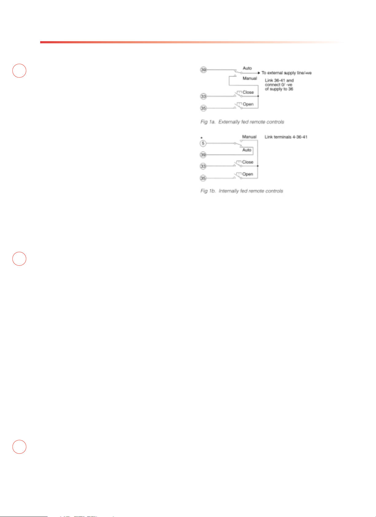
CONNECTIONS
The analogue signal should be connected to terminals 26 (+ve)
and 27 (-ve). If no remote manual control is required, link
terminals 39 to 5 and 41 to 4. Terminal 39 is provided for
remote manual/auto selection. The remote control connections
for actuators to standard wiring diagrams are as follows:
CURRENT POSITION TRANSMITTER (CPT)
The CPT provides an internally powered electrically isolated 420mA analogue valve position feedback signal, which is
available at terminals 22 (+ve) and 23 (-ve). The maximum
external impedence that may be connected to the signal is 500
ohms. Repeatability is within ±1% and linearity ±2.5% of total
valve travel.
ALARM RELAYS
A set of three alarm relays can be provided with the following
functions:
Relay 1 ‘Battery low’ signal (Normally open contact
rated for 5A 250 volts AC, 30 volts DC).
Relay 2 ‘Thermostat tripped’ signal (change-over
contact rated for 30 Watts, 62.5VA, 110 Volts).
Relay 3 ‘Remote selected’ signal (contact as Relay 2)
The following optional facilities available on standard IQ
actuators are also available on IQM units.
Negative Switching (see publication E120E)
Interrupter Timer (see publication E120E)
Pakscan (see publication S000E)
IQM - OPTIONAL FACILITIES
Page 4

4
IQM - ACTUATOR CONTROL CIRCUITS
BASIC IQM ACTUATOR WIRING DIAGRAM 5000-000
Positive switching remote controls. Refer to Rotork for nonstandard voltage option. Circuit is drawn with power supply off.
Transformer Tapping Options
Type 1
TAP NOM 50/60HZ 50HZ 60HZ
W 220/230 176-242 198-259
X 380/400 304-418 342-446
Y 415/420 332-457 374-487
Z 440/460 352-484 396-517
Fuse FS1 - 250mA Anti-Surge
Type 2
TAP NOM 50/60HZ 50HZ 60HZ
W 346/380 285-388 321-419
X 480/500 406-552 432-564
Y 240/240 192-261 216-282
Z* 550/575 445-605 501-654
Fuse FS1 250mA Anti-Surge
NOTE *150mA Anti-Surge
The actuator must be protected using
suitably rated high speed semi-conductor
fuses on the incoming supply.
Suggested fuses:-
IQ10-20: 10 Amp Ferraz G330010
IQ25-35: 20 Amp Ferraz K330013
All transformer types - PS1 Self resetting fuse
NOTE
Where customers wish to have the
thermostat by-passed during emergency
shutdown operation, it should be noted that
any actuator hazardous enclosure
certification will be invalidated while the
thermostat is by-passed.
Max external load on terminals 4&5 to be
5W.
For typical remote control
indicating,monitoring and alarm circuits see
publication E420E
Control signal threshold voltages to be
minimum ‘ON’ 20V AC/DC maximum ‘OFF’=
3V minimum control signal duration to be
100mS.
Current drawn from each remote control
signal is 5mA on 24V DC
Wires are identified at each end by terminal
No. or tag No.
Iindication contacts S1-S4 are shown in their
default configuration. Contacts may be
configured for any of the functions described
in E170E.
OPEN
%
S4
S1
S2
S3
MONITOR
RELAY
SK.3
SK.1
SK.4
2
1
3
1
2
3
4
5
6
7
8
24
30
SK.14
SK.10
SK2
SK1 SK4
SSS MODULE
SK9
SK11
MOTOR
3456
2A 2B
1
LK1
U
V
U
W
XWYZ
24V DC SUPPLY
0V DC SUPPLY
3
24VDC
0VDC
24VDC
NOMINAL SUPPLY
2
1
5
4
1
5
4
PS1
W
U
V
1
3
2
SK.1
SK.3
FS1
E
3
PHASE
SUPPLY
CIRCUIT DRAWN WITH POWER SUPPLY OFF
9
7
10
13
11
12
8
6
43
44
42
SK.12SK.1
LOCAL
CONTROL
PCB
SK.7
SK.9
2
1
LIMIT
PCB
SENSING
SK.1
-
+
BATTERY
FS2 100mA(ONLY FITTED
ON CENELEC ACTUATORS)
32
31
38
25
36
34
37
40
35
33
T/STAT BYPASS - ESD
OPEN
CLOSE INTERLOCK
OPEN INTERLOCK
STOP/MAINTAIN
CLOSE
COMMON -VE 24V DC
COMMON -VE 24V DC
SK.2
SK.8
3
4
2
1
5
1
4
3
5
2
TORQUE
SENSOR
4
5
SK.6
SK.5
FS2
INFRA-RED
DIGITAL POSITION
INDICATION UNIT
2W
1
V
U
1pm
2pm
3pm
3
MAKE AT FULLY
SHUT
MAKE AT FULLY
OPEN
BREAK AT FULLY
SHUT
BREAK AT FULLY
OPEN
Page 5

5000-000 5100-000 5000-100 5100-100
5010-000 5110-00 5010-100 5110-100
5
IQM - OPTIONAL FEATURES
STANDARD ACTUATOR DIAGRAMS
The typical remote control interlock and monitoring circuits
illustrated are applicable to actuators with the following
standard Rotork wiring diagrams.
NOTES
1 Data logger - diagram number changes to ‘1’ for fifth
digit, e.g. 600-000 becomes 600-010.
2 For negative switching - diagram number changes to ‘7’
for first digit, e.g. 600-000 becomes 700-000.
IQ SETTING TOOL
The IQ Setting Tool makes it possible to read and set all the
actuator functions, such as valve travel and torque or travel
limit control, without removing any covers. The IQ Setting Tool
transmits signals to an infra-red receiver built into the actuator.
The IQ Setting Tool has a ‘programming’ mode which enables
the valve manufacturer to configure the actuator to suit his
valve and the site commisioning engineer to configure the
actuator for a variety of different control functions. The IQ
Setting Tool also has a ‘checking’ mode which enables all the
existing actuator settings to be interrogated. Protection against
unauthorized changes to setting is provided by a ‘password’.
CONFIGURATION
The following actuator functions are configured by the IQ
Setting Tool:
• Direction of actuator output rotation for closing the valve.
• Selection of torque or turns limitation for valve opening
and closing travel.
• Torque setting for Open and Close valve operation.
• Setting of actuator output turns to suit the valve travel.
• “Open/close” remote control signal priority.
• Selection of function and contact mode for each of the
four standard indication contacts.
• Valve to Open or Close with ESD signal.
• External interlock facility.
The standard configuration for the IQM actuator is given on page 6.
In addition, the IQ Setting Tool will enable configuration of the
following optional assemblies when fitted to the actuator:
• CPT - selection of open or closed valve position
corresponding to a maximum signal.
• Pakscan - address, baud rate and protocol.
• Folomatic - signal range, increasing signal is to correspond
to opening or closing of the valve, action on loss of signal,
amount of deadband and the motion inhibit time delay.
Publication E170E, supplied with each actuator gives full
instructions for the operation of the IQ Setting Tool.
Page 6

6
IQM - REMOTE DIGITAL CONTROL CIRCUITS
The infra red setting tool enables various different remote
controls to be configured. Unless specified requirements are
stated with the order, actuators will be supplied configured as
follows:
Maintained local control
Clockwise to close
Thermostat by-passed on ESD
Open and closed interlocks enabled
Close signal priority
The typical remote control circuits shown below apply to these
unless otherwise stated.
Max. external load on 24v DC supply from
acutuator terminals 4 - 5 to be 5W.
Form A
Open/close push to run control
(local control remains self maintained).
Form F
Emergency shut-down to close valve overriding
thermostat (actuator hazardous enclosure
certification is invalidated while thermostat
overidden) and any existing signal may be
added to any of the circuits above.
Actuators may be configured so that thermostat
is not by-passed during ESD operation.
To override external interlocks on ESD additional
remote contacts must be provided.
Brake enable connections
† Note
Remote controls may be fed from the internal 24V DC supply at
terminal 5 when terminals 4-36 must be linked, or from an
external supply when the zero/-ve of the supply should be
connected to terminal 36.
Terminals 4-36 also to be linked for form A and F control.
The input to the IQ series actuator logic circuits associated with
the remote controls may be used with cable capacitance of up
to 2µF between cores.
Page 7

7
IQML10 TO IQML25 ACTUATOR DIMENSIONS
IQML10 IQML25
Page 8

As part of a process of on-going product
development, Rotork reserves the right
to amend and change specifications
without prior notice.
Published data may be subject to change.
For the very latest version release, visit
our website at www.rotork.com
The name Rotork is a registered trademark.
Rotork recognizes all registered trademarks.
Published and produced in the UK by
Rotork Controls Limited.
A full listing of our worldwide
sales and service network
is available on our website at
www.rotork.com
UK head office
Rotork Controls Limited
telephone Bath 01225 733200
telefax 01225 333467
email mail@rotork.co.uk
USA head office
Rotork Controls Inc
telephone Rochester (585) 328 1550
telefax (585) 328 5848
email info@rotork.com
Rotork Controls Ltd, Bath, UK
Rotork Controls Inc, Rochester, USA
‘IQM’ & ‘IQML’ RANGE
CONTROL AND
MONITORING
FACILITIES
 Loading...