

Page 1

Page 2

1.0 INTRODUCTION .......................................................................................................................................... 7
1.1 INSTALLING INSIGHT 2 .................................................................................................................................. 7
1.2 UNINSTALLING INSIGHT 2 .............................................................................................................................. 7
1.3 UPDATING INSIGHT 2 ................................................................................................................................... 7
2.0 LOGGING IN ............................................................................................................................................... 8
2.1 LOGIN SCREEN ............................................................................................................................................ 8
2.2 USER LEVELS .............................................................................................................................................. 8
2.2.1 Viewer ............................................................................................................................................. 8
2.2.2 User ................................................................................................................................................ 9
2.2.3 Service_Engineer ............................................................................................................................. 9
2.2.4 Administrator .................................................................................................................................. 9
3.0 HOME SCREEN ......................................................................................................................................... 10
3.1 LAYOUT .................................................................................................................................................. 11
3.2 MENU BAR .............................................................................................................................................. 12
3.2.1 File ................................................................................................................................................ 12
3.2.2 Connection .................................................................................................................................... 15
3.2.3 Security ......................................................................................................................................... 15
3.2.4 Tools ............................................................................................................................................. 16
3.2.5 Help .............................................................................................................................................. 17
3.3 ICON BAR ................................................................................................................................................ 18
3.3.1 Open Configuration ....................................................................................................................... 18
3.3.2 Save As .......................................................................................................................................... 18
3.3.3 Save .............................................................................................................................................. 18
3.3.4 Print .............................................................................................................................................. 18
3.3.5. Send Configuration ....................................................................................................................... 18
3.3.6 Read Configuration ........................................................................................................................ 18
3.3.7 Discard .......................................................................................................................................... 18
3.4 SIDE PANEL .............................................................................................................................................. 19
3.4.1 Offline ........................................................................................................................................... 19
3.4.2 Bluetooth ...................................................................................................................................... 19
3.5 RANGE PANEL .......................................................................................................................................... 20
3.6 PRESENTATION WINDOW ............................................................................................................................ 21
3.7 STATUS BAR ............................................................................................................................................. 21
3.7.1 Connection Status .......................................................................................................................... 21
3.7.2 Actuator Login Level ...................................................................................................................... 21
3.7.3 Insight 2 Login Level ...................................................................................................................... 21
4.0 CONNECTING AND DISCONNECTING DEVICES .......................................................................................... 22
4.1 SEARCHING FOR DEVICES ............................................................................................................................. 22
4.2 CONNECTING TO AN ACTUATOR .................................................................................................................... 23
4.3 CONNECTING TO A BLUETOOTH SETTING TOOL ................................................................................................. 23
4.4 DISCONNECTING FROM DEVICES .................................................................................................................... 23
5. CVA ............................................................................................................................................................ 24
5.1 CVQ/CVL DEVICE INFORMATION ................................................................................................................. 25
5.1.1 Valve Tag ...................................................................................................................................... 25
5.1.2 CVA/CVQ Type ............................................................................................................................... 25
5.1.3 CVA Main PCB Software Version .................................................................................................... 25
5.1.4 Manufacturing Data ...................................................................................................................... 25
5.1.5 Service Notes ................................................................................................................................. 25
5.1.6 Date of Manufacture ..................................................................................................................... 25
5.1.7 CVA Hardware ............................................................................................................................... 25
2
Page 3

5.1.8 Main Controller Serial No. .............................................................................................................. 25
5.1.9 UPS Controller Serial No. ................................................................................................................ 25
5.1.10 Position Sensor Serial No. ............................................................................................................. 25
5.1.11 Motor Sensor Serial No. ............................................................................................................... 25
5.1.12 Force Sensor Serial No. ................................................................................................................ 26
5.1.13 User Interface Serial No. .............................................................................................................. 26
5.2 ACTUATOR CONFIGURATION - CVA VALVE SETUP ............................................................................................. 26
5.2.1 Valve Action Settings ..................................................................................................................... 26
5.2.2 MOVTag ........................................................................................................................................ 26
5.2.3 Valve Action Settings ..................................................................................................................... 26
5.2.4 Input / Output Setup ...................................................................................................................... 27
5.3 ADVANCED SETTINGS 1 ............................................................................................................................... 27
5.3.1 Tight Shut Off ................................................................................................................................ 27
5.3.2 Obstruction Action Active .............................................................................................................. 27
5.3.3 Obstruction Values Setup ............................................................................................................... 28
5.3.4 Manual Test Knob Setup ................................................................................................................ 28
5.4 ADVANCED SETTINGS 2 ............................................................................................................................... 28
5.4.1 Travel Alarm Thresholds ................................................................................................................ 28
5.4.2 Bumpless Transfer Setup ................................................................................................................ 28
5.5 UPS CONFIGURATION AND STATUS ............................................................................................................... 29
5.5.1 UPS Configuration ......................................................................................................................... 29
5.5.2 UPS Status Information .................................................................................................................. 30
5.6 CVA STATUS ............................................................................................................................................ 30
5.6.1 Actuator Position (%) ..................................................................................................................... 30
5.6.2 Actuator Torque (%) ...................................................................................................................... 30
5.6.3 Analogue Demand Input (mA) ........................................................................................................ 30
5.6.4 Analogue Position Feedback (mA) .................................................................................................. 30
5.6.5 ESD Input Status ............................................................................................................................ 30
5.7 CVA MAIN DATALOGGER ............................................................................................................................ 31
5.7.1 Event Logger ................................................................................................................................. 31
5.7.2 CVA Dwell Log ............................................................................................................................... 34
5.7.3 CVA Torque Logs ............................................................................................................................ 34
5.7.4 CVA Movement Log ....................................................................................................................... 35
6.0 IQ3 SETTINGS ........................................................................................................................................... 36
6.1 ACTUATOR INFORMATION ........................................................................................................................... 38
6.1.1 Actuator User Information ............................................................................................................. 38
6.1.2 Actuator Serial Numbers ................................................................................................................ 38
6.1.3 Actuator Manufacturing Information ............................................................................................. 39
6.2 ACTUATOR NAME PLATE ............................................................................................................................. 40
6.2.1 Actuator Name Plate Info .............................................................................................................. 40
6.2.2 Valve Manufacturing Information .................................................................................................. 41
6.2.3 Gearbox Manufacturing Information ............................................................................................. 42
6.3 ACTUATOR SETTINGS .................................................................................................................................. 43
6.3.1 Basic Settings ................................................................................................................................ 43
6.3.2 ESD Configuration.......................................................................................................................... 44
6.3.3 REMOTE CONFIGURATION ........................................................................................................................ 45
6.3.4 Local Configuration........................................................................................................................ 45
6.3.5 Special Mode Configuration ........................................................................................................... 46
6.4 TORQUE SETTINGS ..................................................................................................................................... 47
6.4.1 Current Torque Readings ............................................................................................................... 47
6.4.2 Actuator Torque Settings ............................................................................................................... 47
6.4.3 Torque Advanced Settings.............................................................................................................. 47
6.4.4 Torque Profile Settings ................................................................................................................... 48
6.5 POWER SETTINGS ...................................................................................................................................... 48
6.5.1 Power Type.................................................................................................................................... 48
6.6 DIGITAL INPUT SETTINGS ............................................................................................................................. 49
3
Page 4

6.6.1 DI Function .................................................................................................................................... 49
6.6.2 DI Input Type ................................................................................................................................. 49
6.7 PARTIAL STROKE SETTINGS........................................................................................................................... 50
6.7.1 Partial Stroke Enable ..................................................................................................................... 50
6.7.2 Partial Stroke Initial Position .......................................................................................................... 50
6.7.3 Partial Stroke Position (%) .............................................................................................................. 50
6.7.4 Partial Stroke Time to Position (sec) ............................................................................................... 50
6.7.5 Partial Stroke Time to Limit (sec) .................................................................................................... 50
6.8 RELAY SETTINGS ........................................................................................................................................ 51
6.8.1 Monitor Relay Function.................................................................................................................. 51
6.8.2 Relay Settings ................................................................................................................................ 52
6.9 OPTION CONTROL ..................................................................................................................................... 53
6.9.1 Option Source Selection ................................................................................................................. 53
6.9.2 Auxiliary Mask Configuration ......................................................................................................... 54
6.9.3 Option 1-4 Configuration ............................................................................................................... 54
6.10 CONTROL SETTINGS ................................................................................................................................. 55
6.10.1 Position Settings .......................................................................................................................... 55
6.10.2 Interrupter Timer ......................................................................................................................... 56
6.11 UI SETTINGS .......................................................................................................................................... 57
6.11.1 Indication Configuration .............................................................................................................. 57
6.11.2 Communication Configuration ..................................................................................................... 58
6.12 LANGUAGE SETTINGS................................................................................................................................ 58
6.12.1 Display Language ........................................................................................................................ 58
6.12.2 Language Option Details .............................................................................................................. 59
6.13 NAMUR SETTINGS ................................................................................................................................... 59
6.13.1 Namur Status .............................................................................................................................. 59
6.13.2 Namur Mask Settings (All groups) ................................................................................................ 60
6.14 ANALOGUE CONTROL/CPT/CTT/AIO OPTION............................................................................................... 60
6.15 EXTRA RELAYS S5-S8 ............................................................................................................................... 60
7.0 IQ3 DATA LOGGER.................................................................................................................................... 61
7.1 EVENT LOGGER ......................................................................................................................................... 62
7.1.1 Time Line ....................................................................................................................................... 62
7.1.2 Trace View..................................................................................................................................... 63
7.1.3 List View ........................................................................................................................................ 64
7.2 TORQUE PROFILE ...................................................................................................................................... 65
7.3 TORQUE LIMIT PROFILES ............................................................................................................................. 65
7.4 TORQUE REFERENCE PROFILE ....................................................................................................................... 66
7.5 TORQUE REFERENCE LIMIT PROFILES .............................................................................................................. 67
7.6 STARTS LOG ............................................................................................................................................. 68
7.7 MOVEMENT LOG ...................................................................................................................................... 69
7.8 CURRENT PARTIAL STROKE PROFILE ............................................................................................................... 70
7.9 VIBRATION TREND LOG ............................................................................................................................... 71
7.10 BATTERY VOLTAGE AND TEMPERATURE TREND LOG ......................................................................................... 72
7.10.1 Battery Voltage Trend .................................................................................................................. 72
7.10.2 Temperature Trend ...................................................................................................................... 72
7.11 MOTOR STARTS AND OUTPUT TURNS TREND LOG ........................................................................................... 73
7.12 MISCELLANEOUS DATALOG DATA ................................................................................................................ 74
7.12.1 Motor Related Data ..................................................................................................................... 74
1.12.2 Power Related Data ..................................................................................................................... 74
1.12.3 Limit Related Data ....................................................................................................................... 75
1.12.4 Environmental Related Data ........................................................................................................ 75
8.0 EH PRO AND SI PRO SCREENS ................................................................................................................... 76
8.1 BASIC SETTINGS ........................................................................................................................................ 78
8.1.1 Valve Tag ...................................................................................................................................... 78
8.1.2 Close Action ................................................................................................................................... 78
4
Page 5

8.1.3 Open Action................................................................................................................................... 78
8.1.4 Close Pressure (Limit) (%) ............................................................................................................... 78
8.1.5 Close Pressure (Mid) (%) ................................................................................................................ 78
8.1.6 Open Pressure (Limit) (%) ............................................................................................................... 78
8.1.7 Open Pressure (Mid) (%) ................................................................................................................ 78
8.1.8 Closed Limit ................................................................................................................................... 78
8.1.0 Open Limit ..................................................................................................................................... 78
8.2 CONTACT RELAYS ...................................................................................................................................... 79
8.2.1 Contact – Function ......................................................................................................................... 79
8.2.2 Contact – Value ............................................................................................................................. 79
8.2.3 Contact – Form .............................................................................................................................. 79
8.3 GENERAL SETTINGS .................................................................................................................................... 80
8.3.1 Remote Select ................................................................................................................................ 80
8.3.2 Configure Local Controls ................................................................................................................ 80
8.3.3 Low Power Mode ........................................................................................................................... 80
8.3.4 Closed LED Colour .......................................................................................................................... 80
8.4 DIGITAL CONTROL ..................................................................................................................................... 81
8.4.1 Remote Priority ............................................................................................................................. 81
8.4.2 Hold Position ................................................................................................................................. 81
8.4.3 Position Hysteresis ......................................................................................................................... 81
8.4.4 Over Pressure Hysteresis ................................................................................................................ 81
8.4.5 Under Pressure Hysteresis .............................................................................................................. 81
8.5 ESD/PARTIAL STROKE ................................................................................................................................ 82
8.5.1 ESD ............................................................................................................................................... 82
8.5.2 Partial Stroke ................................................................................................................................. 83
8.5.3 Reference Partial Stroke Test Recorded Values ............................................................................... 83
8.6 ANALOGUE CONTROL ................................................................................................................................. 84
8.6.1 Analogue Control ........................................................................................................................... 84
8.6.2 Flow Characterisation .................................................................................................................... 85
8.7 INTERRUPTER TIMER .................................................................................................................................. 86
8.7.1 Interrupter Timer ........................................................................................................................... 86
8.7.2 Interrupter Timer Direction ............................................................................................................ 86
8.7.3 Interrupter Timer Start (%) ............................................................................................................. 86
8.7.4 Interrupter Timer Stop (%) ............................................................................................................. 86
8.7.5 Interrupter Timer Interval .............................................................................................................. 86
8.7.6 Interrupter Timer On Time ............................................................................................................. 86
8.7.7 Interrupter Timer Off Time ............................................................................................................. 86
8.7.8 Interrupter Timer with ESD Enabled ............................................................................................... 86
8.8 ACTUATOR STATISTICS ................................................................................................................................ 87
8.8.1 Number of Times Open Limit Reached ............................................................................................ 87
8.8.2 Number of Times Close Limit Reached ............................................................................................ 87
8.8.3 Time Spent Moving Open (sec) ....................................................................................................... 87
8.8.4 Time Spent Moving Closed (sec) ..................................................................................................... 87
8.8.5 Number of ESD Events ................................................................................................................... 87
8.8.6 Number of Motor Starts ................................................................................................................. 87
8.8.7 Number of Accumulator Recharges ................................................................................................ 87
9.0 BLUETOOTH SETTING TOOL SCREENS ....................................................................................................... 88
9.1 BTST INFORMATION .................................................................................................................................. 88
9.1.1 Firmware Version .......................................................................................................................... 88
9.1.2 Battery Status (mV) ....................................................................................................................... 88
9.1.3 Number of Files ............................................................................................................................. 88
9.1.4 Free Space on the BTST (Bytes) ...................................................................................................... 88
9.1.5 Flash Memory size on BTST (Bytes)................................................................................................. 88
9.2 CVA ...................................................................................................................................................... 88
9.3 IQ2 ....................................................................................................................................................... 89
9.4 EHP ...................................................................................................................................................... 89
5
Page 6

9.5 IQ3 ....................................................................................................................................................... 89
9.6 SIP ........................................................................................................................................................ 89
9.7 MISSIONS ................................................................................................................................................ 89
9.7.1 Create Missions ............................................................................................................................. 89
9.7.2 Custom Mission ............................................................................................................................. 92
9.7.3 Review/Edit Mission ...................................................................................................................... 93
9.7.4 Delete Mission ............................................................................................................................... 93
9.7.5 Delete All Missions......................................................................................................................... 93
9.7.6 Format BST .................................................................................................................................... 94
6
Page 7

1.0 Introduction
1.1 Installing Insight 2
1.2 Uninstalling Insight 2
1.3 Updating Insight 2
1.1 Installing Insight 2
The Insight 2 program can be downloaded from the Insight 2 download page on:
www.rotork.com/en/support/index/downloads
You will be required to Log in with your Rotork Internet Portal Account to access this page.
(To register for a free Rotork Internet Portal Account click register and fill out the application form)
On the IQ Insight 2 download page you can view information about the software and the minimum
PC operating requirements. It is worth noting down the program access passwords for future use.
When you are satisfied that your machine is compatible with Insight 2, click Download IQ-Insight 2
Software for PC. This will begin the software package download for the latest version of Insight 2.
Once the download is complete, extract the install package to a user specified save location. Open
the Setup.exe file to load the installation wizard and begin the program install process. Follow the
on-screen prompts to install Insight 2.
1.2 Uninstalling Insight 2
To uninstall Insight 2 use the Uninstall Insight 2 start menu shortcut or proceed through the standard
Windows software management feature. This can be found within the control panel.
For XP users use the “Add/Remove Programs” feature.
For Vista and 7 users use the “Uninstall a program”
feature.
Select Insight 2 from the program list and select uninstall. Follow the onscreen wizard to complete
the removal of Insight 2.
1.3 Updating Insight 2
Insight 2 will be updated periodically to add new features and increased compatibility with new
Rotork actuators. To update your copy of Insight 2 please follow instructions detailed on the
download page of the Rotork website www.rotork.com/en/support/index/downloads.
7
Page 8

2.0 Logging In
2.1 Login Screen
2.2 User Levels
2.2.1 Viewer
2.2.2 User
2.2.3 Service Engineer
2.2.4 Administrator
2.1 Login Screen
Below is the login screen for Insight 2.
This screen provides the user with four access levels on a drop down menu that require the
corresponding passwords to be entered. The check box in the bottom left allows Insight 2 to
remember your login details for easy access to the program in the future.
2.2 User Levels
The Privilege Level drop down menu presents 4 selections.
This selection will determine the available access levels visible when connecting to a Rotork
Bluetooth device.
2.2.1 Viewer
As a Viewer you can connect to any Bluetooth equipped Rotork device. These include: IQ3, CVA, EH
Pro, SI Pro and Rotork Bluetooth Setting Tool Pro. Viewer level prevents operators from modifying
the settings of an actuator.
Default Insight 2 Viewer Password: ROTORK
8
Page 9

2.2.2 User
As a User you can perform all the tasks of a Viewer with the ability to modify setting values. An
actuator User login allows you to change some settings within the actuators configuration.
Default Insight 2 User Password: ROTORK
2.2.3 Service Engineer
This login is reserved for the use of Rotork Service Engineers.
2.2.4 Administrator
This Login is reserved for the use of Rotork Engineers.
9
Page 10

3.0 Home Screen
3.1 Layout
3.2 Menu Bar
3.2.1 File
3.2.2 Connection
3.2.3 Security
3.2.4 Tools
3.2.5 Help
3.3 Icon Bar
3.3.1 Open Configuration
3.3.2 Save As
3.3.3 Save
3.3.4 Print
3.3.5 Send
3.3.6 Receive Configuration
3.3.7 Discard
3.4 Side Panel
3.4.1 Offline
3.4.2 Bluetooth
3.5 Range Panel
3.6 Presentation Window
3.7 Status Bar
3.7.1 Connection Status
3.7.2 Actuator Login level
3.7.3 Insight 2 Login Level
10
Page 11

3.1 Layout
Description
Colour
Menu Bar
Blue Icon bar
Orange
Side Panel
Purple
Range Panel
Yellow
Presentation Window
Green
Status Bar
Red
For the purpose of this manual the main Insight 2 screen has been split into six areas as shown
below.
11
Page 12
3.2 Menu Bar
3.2.1 File
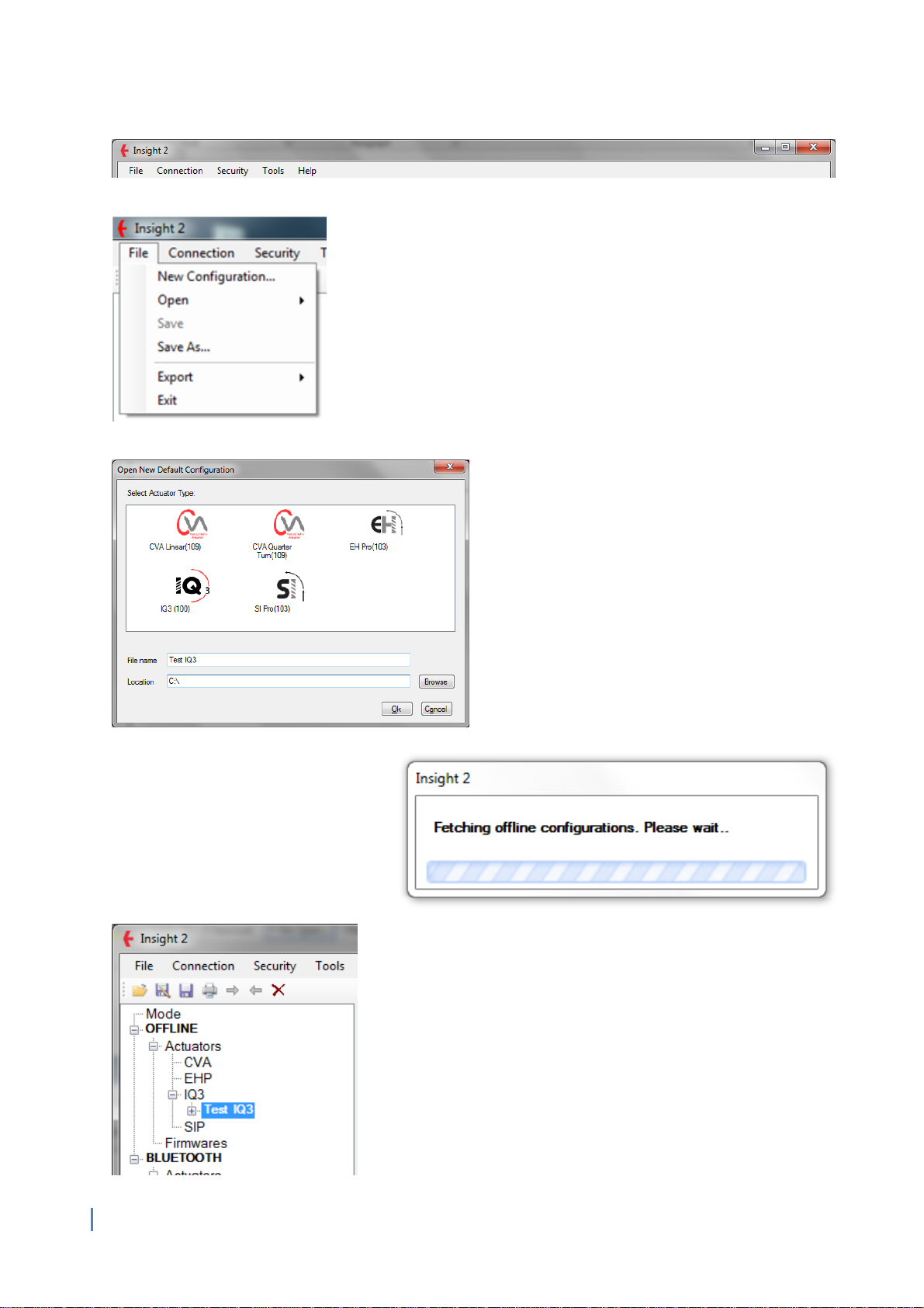
New Configuration
Use this function to create a new
default configuration for a compatible
Rotork product. There are 5 types of
actuator that can be configured with
Insight 2. The name and save location
of the configuration can be modified
appropriately if required.
Once “Ok” is selected the loading screen will appear as Insight 2
prepares the new configuration. This will appear in the Offline
section of the side menu (for side menu information see section
3.4.1) under the correct actuator type.
NOTE: using this function on a live actuator will clear any
previous configuration. Ensure a copy of the existing
configuration is saved before using this feature.
12
Page 13

Open
Configuration
The configuration option allows the user to open saved configuration files. Opened files will be shown in
the Offline section of the Side menu under the relevant actuator type.
Firmware
This function is only available for Rotork Service Engineers and Service centres.
Save
When a configuration in the Offline section is changed the user can save those changes.
13
Page 14

Save As
This function enables the user to save configuration files from the Offline or Online sections of the side
menu to a directory on the PC. These will be available for future offline use. This feature is to be used
for saving the configuration and datalogger files in the format to be read by Insight 2. For other formats
use the export feature.
Export
Configuration
This exports the current actuator configuration as either a Comma Separated Value (.csv) or a Text file
(.txt)
Configuration and DataLogs
This exports the current actuator configuration and data log file as either a Comma Separated Value
(.csv) or a Text file (.txt). The data log must be viewed within Insight 2 prior to exporting the data.
Exit
The Exit function will close Insight 2 and disconnect from any active Bluetooth device.
14
Page 15

3.2.2 Connection
Discover Devices
This initialises a search for all Bluetooth enabled actuators* and setting tools within the Bluetooth
adaptor range (setting tools can only be found whilst in slave mode, refer to the Bluetooth Setting Tool
manual for more information).
Recent Discovered Devices
This provides a list of previously connected devices that the operator can connect to without requiring a
Bluetooth search*.
*Actuators must be in a Bluetooth visible mode and within range of the Bluetooth adapter to be
discovered with Insight 2.
3.2.3 Security
Change Privilege
This enables the user to change their privilege level within Insight 2 by re-opening the Login screen (see
section 2 Logging In).
Change Application Password
This function enables the current user to change the Insight 2 login passwords for the current privilege
level and any lower privilege level.
15
Page 16

Change Actuator Password
This function is reserved for Rotork Service Engineer use only.
3.2.4 Tools
Sensor Calibration
This function is reserved for Rotork Service Engineer use only.
Zero Thrust
This function is reserved for Rotork Service Engineer use only.
CP Chat
This function is reserved for Rotork Service Engineer use only.
Unit Setting
The units displayed within Insight 2 can be set to Metric or Imperial to suit various global markets
(Insight 2 default = Metric).
Install Actuator Devices
This function enables Insight 2 to be updated using a compressed ADF file package provided by Rotork.
All future updates will be supported via this feature to ensure reliable compatibility with the continually
expanding Rotork product offering.
To download the latest ADF file please visit the Insight 2 download page:
http://www.rotork.com/customers/index/iqinsight2.
Save the ADF file to an accessible PC directory and then browse to the file through the Install Actuator
Devices function.
16
Page 17

On successful installation of the update you will be requested to restart Insight 2.
3.2.5 Help
View Help
Insight 2 Help
This help file is currently under construction. Future releases will include information about various
Insight 2 functions.
Actuator Help
This help file is currently under construction. Future releases will include information about various
Rotork actuator functions relevant to the connected actuator type.
About Us
Shows the current version number of the Insight 2 program and contains a brief description about the
purpose of Insight 2.
17
Page 18

3.3 Icon Bar
3.3.1 Open Configuration
This allows the user to open a saved Configuration file (.icf) from a PC directory in the Offline
section of the Side panel.
3.3.2 Save As
This function enables configuration files from the Offline or Online sections of the side menu to
be saved in a PC directory.
3.3.3 Save
When a configuration is open in the Offline Section, this function enables the user to save any
modifications to the settings.
3.3.4 Print
This will print the current information in the presentation window as it is shown on the screen
(only available when actuator information is displayed within the window).
3.3.5. Send Configuration
This function will send all visible configuration changes to the connected actuator. Send
Configuration will only be possible when connected to a Bluetooth device.
3.3.6 Read Configuration
This function will read a device’s current configuration. Read Configuration will only be possible
when connected to a Bluetooth device.
3.3.7 Discard
Removes any unsaved configuration changes (highlighted yellow) displayed within the
presentation window.
18
Page 19

3.4 Side Panel
Fig 1
Fig 2
3.4.1 Offline
Actuators
All offline actuator configurations opened in Insight 2 are stored for the session under their respective
actuator type (see Fig 1). Configurations can be edited and viewed (with the correct privilege level) from
the expanded menu (See fig 2).
Firmware
This function is reserved for Rotork Service Engineer use only.
3.4.2 Bluetooth
Actuators
All actuators that have been found by after a Bluetooth search (see 1.0 and 4.0) will be visible here. The
expanded menu can only be accessed once a connection to the device has been established.
19
Page 20

Bluetooth Setting Tool
All visible Bluetooth Setting Tools currently in slave mode and available for connection (See Bluetooth
Setting Tool Manual for details) will be visible in this section. The expanded menu can only be accessed
once a connection to the Bluetooth Setting Tool has been established.
3.5 Range Panel
The Range Panel will indicate which actuator range the current configuration or data log belongs to. If
the device is currently connected through Insight 2 the serial number and valve tag will also be
displayed.
20
Page 21

3.6 Presentation Window
The presentation window is where all configuration and data log information is displayed. Any setting
entries that are shaded grey are non-editable at the current privilege level.
3.7 Status Bar
Current status of actuator connection, actuator privilege level and Insight 2 privilege level are displayed
at all times within the Insight 2 window.
3.7.1 Connection Status
Connection status for Insight 2 is visible in the left portion of the status bar. An online connection will
show the actuator Bluetooth tag or Bluetooth Setting Tool tag and the connection method. If a
Bluetooth connection is not currently active an offline status will be displayed.
3.7.2 Actuator Login Level
Current actuator login level is shown in the middle portion of the status bar. There are three levels
available: Viewer, User and Engineer.
3.7.3 Insight 2 Login Level
The current privilege level access for Insight 2 is displayed in the right portion of the status bar. To
change access level, click on this part of the status bar or use the change privilege level option (See
3.2.3.1).
21
Page 22

4.0 Connecting and Disconnecting Devices
4.1 Searching for Devices
4.2 Connecting to an Actuator
4.3 Connecting to a Bluetooth Setting Tool
4.4 Disconnecting from Devices
4.1 Searching for Devices
Use the Discover Devices function (as detailed in 3.2). This will begin a search for all Rotork Bluetooth
enabled devices and setting tools within range of the Bluetooth adapter.
Please note only actuators with a Bluetooth Security setting of Medium or Low are visible within Insight
2. Bluetooth setting Tools have to be in slave mode to be found by Insight 2 (refer to the Bluetooth
Setting Tool Manual for information on how to activate Slave Mode).
Once the search is complete, all actuators found will be displayed in the expanded menu under the
relevant range heading. Each unit will be identified by Serial Number and Bluetooth Friendly Tag.
Bluetooth Setting Tools will be identified by the acronym BST and the Bluetooth MAC address.
22
Page 23
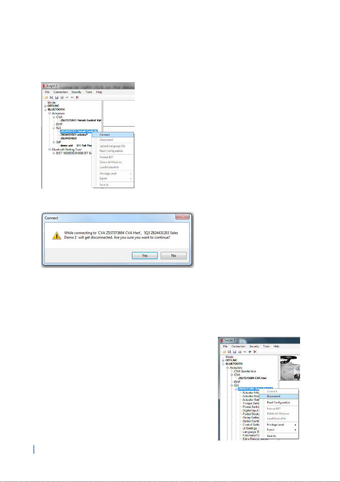
4.2 Connecting to an Actuator
To connect to an actuator, double click on the actuator name or right click on the actuator name and
click Connect.
If you try to connect to more than one actuator the warning box below will be shown.
4.3 Connecting to a Bluetooth Setting Tool
Connecting to a Bluetooth Setting Tool is performed in the same manner as connecting to an actuator.
Upon connection with Insight 2 the Setting Tool’s Enter key will rapidly flash blue indicating a
connection has been established. The connection privilege Level of the Bluetooth Setting Tool is
dictated by the current Insight 2 Privilege Level.
4.4 Disconnecting from Devices
You can disconnect from a device by right clicking the device and
selecting Disconnect from the drop down menu, this is applicable
to all Bluetooth devices.
23
Page 24

5. CVA
5.1 CVQ/CVL Device Information
5.1.1 Valve Tag
5.1.2 CVA/CVQ Type
5.1.3 CVA Main PCB Software Version
5.1.4 Manufacturing Data
5.1.5 Service Notes
5.1.6 Date of Manufacture
5.1.7 CVA Hardware
5.1.8 Main Controller Serial No.
5.1.9 UPS Controller Serial No.
5.1.10 Position Sensor Serial No
5.1.11 Motor Sensor Serial No.
5.1.12 Force Sensor Serial No.
5.1.13 User Interface Serial No.
5.2 Actuator Configuration - CVA Valve Setup
5.2.1 Valve Action Settings
5.2.2 MOVTag
5.2.3 Valve Action Settings
5.2.4 Input / Output Setup
5.3 Advanced Settings 1
5.3.1 Tight Shut Off
5.3.2 Obstruction Action Active
5.3.3 Obstruction Values Setup
5.3.4 Manual Test Knob Setup
5.3.5 CVA Status Relay Setup
5.4 Advanced Settings 2
5.4.1 Travel Alarm Thresholds
5.4.2 Bumpless Transfer Setup
5.4.3 Manual Test Knob Setup
5.4.4 CVA Status Relay Setup
5.4.5 Travel Alarm Thresholds
5.4.6 Bumpless Transfer Setup
5.5 UPS Configuration and Status
5.5.1 UPS Configuration
5.5.2 UPS Status Information
5.6 CVA Status
5.6.1 Actuator Position (%)
5.6.2 Actuator Torque/Thrust (%)
5.6.3 Analogue Demand Input (mA)
5.6.4 Analogue Position Feedback (mA)
5.6.5 ESD Input Status
24
5.7 CVA Data logger
Page 25

5.7.1 Event Log
5.7.2 Dwell Log
5.7.3 Torque/Thrust Logs
5.7.4 Movement Log
5.1 CVQ/CVL Device Information
Please note that CVA actuators should be configured using dedicated Enlight support software. This is
available to download free of charge from www.rotork.com.
5.1.1 Valve Tag
This is a user defined name for the actuator consisting of up to 32 alpha-numeric or symbolic characters.
It is normally used by operators to specify a unique tag based on location or a description of the
actuator. This setting is linked directly to the MOVTag in the CVA Valve Setup Menu (See Section 5.2.2).
5.1.2 CVA/CVQ Type
This displays the size of the actuator, along with any options fitted. Rotork Service Engineer use only.
5.1.3 CVA Main PCB Software Version
Shows the current Main PCB software version in the actuator. Rotork Service Engineer use only.
5.1.4 Manufacturing Data
Shows the manufacturing data for the actuator. Rotork Service Engineer use only.
5.1.5 Service Notes
This is where service notes can be entered and stored for future reference. This field accepts up to 64
characters. Rotork Service Engineer use only.
5.1.6 Date of Manufacture
Shows the date of manufacture in the format YYYY/MM/DD. Rotork Service Engineer use only.
5.1.7 CVA Hardware
Shows the current CVA Hardware Number. Rotork Service Engineer use only.
5.1.8 Main Controller Serial No.
This is where the Main Controller serial number can be entered and viewed. Rotork Service Engineer use
only.
5.1.9 UPS Controller Serial No.
This is where the UPS Controller serial number can be entered and viewed. Rotork Service Engineer use
only.
5.1.10 Position Sensor Serial No.
This is where the Position Sensor serial number can be entered and viewed. Rotork Service Engineer use
only.
5.1.11 Motor Sensor Serial No.
This is where the Motor Sensor serial number can be entered and viewed. Rotork Service Engineer use
only.
25
Page 26

5.1.12 Force Sensor Serial No.
This is where the Force Sensor serial number can be entered and viewed. Rotork Service Engineer use
only.
5.1.13 User Interface Serial No.
This is where the User Interface serial number can be entered and viewed. Rotork Service Engineer use
only.
5.2 Actuator Configuration - CVA Valve Setup
5.2.1 Valve Action Settings
Valve Open Torque/Thrust Setting (%)
The slider sets the percentage of rated torque/thrust the actuator will be limited to during operation in
the open direction. This is adjustable between 40% and 100%.
Valve Close Torque/Thrust Setting (%)
The slider sets the percentage of rated torque/thrust the actuator will be limited to during operation in
the closed direction. This is adjustable between 40% and 100%.
5.2.2 MOVTag
Valve Tag
This is a user defined name for the actuator consisting of up to 32 alpha-numeric or symbolic characters.
It is normally used by operators to specify a unique tag based on location or a description of the
actuator. This setting is linked directly to the Valve Tag in the CVQ/CVL Device Information Menu (See
Section 5.1.1).
5.2.3 Valve Action Settings
Shaft Action
Specify the output direction of the actuator. CVL actuators can be configured for extend to close or
extend to open operation. CVQ actuators can be configured for clockwise to close or anti-clockwise to
close.
26
Page 27

Open Stop Action
The actuator can be set to stop in the open direction when it reaches the open position limit or when it
reaches the defined open torque/thrust setting value (see section 5.2.1).
Close Stop Action
The actuator can be set to stop in the close direction when it reaches the close position limit or when it
reaches the defined close torque/thrust setting value (see section 5.2.1).
5.2.4 Input / Output Setup
Demand Deadband (%)
The demand deadband sets the expected positioning accuracy of the actuator and is dependent on
various factors including actuator output speed, number of turns and valve torque. The actuator will run
until it reaches a position within the demanded deadband. The actuator will not restart until the
demanded position exceeds the extent of the deadband.
Demand Damping Clockwise (secs)
Setting a value greater than 0 will apply a delay in the clockwise direction, temporarily inhibiting
movement when a change to the set point signal occurs.
Demand Damping Anti-Clockwise (secs)
Setting a value greater than 0 will apply a delay in the anti-clockwise direction, temporarily inhibiting
movement when a change to the set point signal occurs.
4-20mA Output
Specify whether the 4-20mA output provides feedback for Valve Position or Valve Torque/Thrust.
5.3 Advanced Settings 1
5.3.1 Tight Shut Off
Valve tight shut off Open position (%)
This is the minimum position required to fully open (tight shut off) the valve.
Valve tight shut off Closed position (%)
This is the maximum position required to fully close (tight shut off) the valve.
5.3.2 Obstruction Action Active
If enabled, the actuator will back off movement if the maximum torque/thrust is exceeded during
travel. The actuator will make 3 attempts to back off and return to the set point. If disabled, the
27
Page 28
actuator will remain stationary until a request to move in the opposite direction is received or the
obstruction is removed. To set up obstruction settings see section 5.3.3.
5.3.3 Obstruction Values Setup
Backoff Distance (%)
The distance the actuator will back off as a percentage of total travel.
Backoff Time (Sec)
The time in seconds before a back off command is executed.
5.3.4 Manual Test Knob Setup
Manual Test Knob Active
Enables or disables the Manual Test knob option provided it is fitted to the actuator.
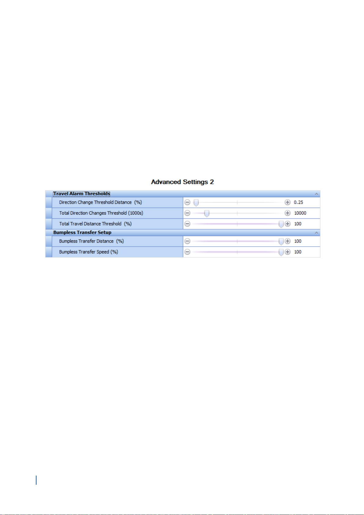
5.4 Advanced Settings 2
5.4.1 Travel Alarm Thresholds
Direction Change Threshold Distance (%)
The distance the actuator must move (as a percentage of full travel) before a direction change is
registered by the data logger as a start. The default setting is 0.25%.
Total Direction Changes Threshold (1000s)
This can be used to generate a Travel Alarm when a set number of direction changes have been
performed by the actuator.
Total Travel Distance Threshold (%)
This can be used to generate a Travel Alarm when a set distance has been travelled by the actuator.
5.4.2 Bumpless Transfer Setup
Bumpless Transfer Distance (%)
This is the percentage of position error that will reduce the actuator speed to the Bumpless Transfer
Speed.
Bumpless Transfer Speed (%)
This is the speed that the actuator will revert to if the bumpless transfer distance is exceeded. It is
measured as a percentage of rated maximum speed and the default setting is 40%.
28
Page 29
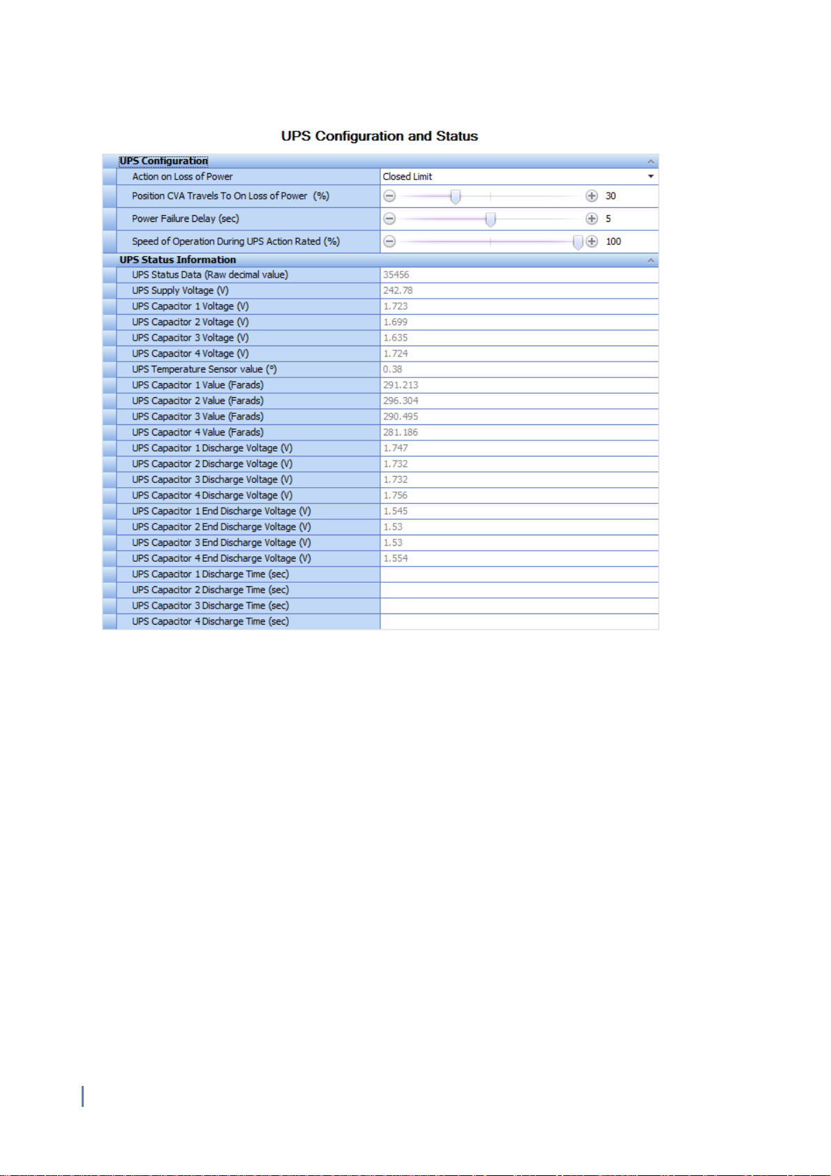
5.5 UPS Configuration and Status
5.5.1 UPS Configuration
Action on Loss of Power
The actuator can be configured to perform four different actions on loss of power. These are:
Closed Limit: The actuator will move to the closed limit.
Open Limit: The actuator will move to the open limit.
Stayput: The actuator will remain at the current position (Default Setting).
Go To Position: The actuator will move to a pre-determined position.
Position CVA travels to on Loss of Power (%)
The position the actuator will travel to on Loss of power, provided the Power Loss Action is set for Go To
Position. The position is a percentage of the full stroke and can be configured in increments of 0.1%.
Powerloss Action Delay timeout (sec)
The delay in seconds before the Power Loss Action is executed. The maximum allowable delay to
guarantee a failsafe action will perform is 10 seconds.
Speed of Operation during UPS action rated (%)
The speed of operation during the UPS action can be adjusted as a percentage of normal operating
speed.
29
Page 30

5.5.2 UPS Status Information
UPS Status Data (Raw Decimal Value)
For indication only, shows the raw decimal value that the UPS supplies to the actuator.
UPS Supply Voltage (V)
For indication only, shows the UPS supply voltage received by the actuator.
UPS Capacitor Voltages (V)
For indication only, shows the charge stored by each capacitor.
UPS Temperature Sensor Value (°C)
For indication only, shows the temperature measured at the UPS.
UPS Capacitor Values (Farads)
For indication only, shows the UPS capacitor values for all fitted capacitors.
UPS Capacitor Discharge Voltages (V)
For indication only, shows the separate discharge voltage for all fitted capacitors.
UPS End Discharge Voltage (V)
For indication only, shows the separate end discharge voltage for all fitted capacitors.
UPS Discharge Time (sec)
For indication only, shows the separate discharge time for each of the fitted capacitors.
5.6 CVA Status
5.6.1 Actuator Position (%)
For indication only, shows the position of the actuator as a percentage of full travel.
5.6.2 Actuator Torque (%)
For indication only, shows the percentage of rated torque currently measured through the actuator
drive train.
5.6.3 Analogue Demand Input (mA)
For indication only, shows the analogue input signal being received by the actuator.
5.6.4 Analogue Position Feedback (mA)
For indication only, shows the output signal being transmitted by the actuator with reference to
position or force (see 5.2.4).
5.6.5 ESD Input Status
For indication only, denotes whether the actuator ESD input is presently active or not.
30
Page 31

5.7 CVA Main Datalogger
The size of the Insight 2 window can be adjusted to expand or retract the visible range on graphical
screens for increased or decreased detail.
5.7.1 Event Logger
The Event Logger will store information related to actuator actions and condition changes. All events
are date and time stamped to accurately assess the actuator operations.
The top scroll bar can be used to navigate from the first recorded event (far left) to the most recent
event (far right). The recorded event number is shown with the event date and event time above the
navigation bar.
Time Line
The Time Line display style provides the user with a visual indication of active conditions for the specific
event selected with the top scroll bar. An active condition is indicated by a checked box. The dropdown
menu is included to apply a filter. The Prev and Next actions buttons chronologically skip to the next
recorded event for the chosen condition.
31
Page 32

Trace View
The trace view provides a comparison between various event triggers during each period between
events. The Position (%) trace is an analogue recorded value whilst other event conditions can be
configured as Digital Traces.
The top scroll bar can be used to navigate through various events. There is
also an additional scroll bar within the Trace view window. This can be
used to adjust the scaling of both traces for more detailed analysis.
Each digital trace can be allocated a different function by opening the
associated drop down menu and selecting the required condition.
32
Page 33

List View
This type of display depicts the Data Log of the CVA in tabular format as a chronological series of events.
The top slider bar can be used to navigate through all available events currently in the data log.
Alternatively the scroll bar on the right side of the event information can be used to navigate events in
the same fashion.
33
Page 34

5.7.2 CVA Dwell Log
The Dwell Log Graph indicates the amount of time spent at each position between the limits of travel.
The graph range extends 25% beyond both limits to account for any actions closing or opening on
torque/thrust beyond the set limits.
Graph detail can be enhanced by dragging a selection area over a section of the graph. This will adjust
the axis to zoom into a full sized graph of that area.
5.7.3 CVA Torque Logs
The torque profile graphs show various traces of torque experienced by the actuator across a full stroke.
The torque reference is a saved stroke trace that is configured during the auto-setup stage when
commissioning the unit. These graphs will display thrust profiles for CVL actuators.
Graph detail can be enhanced by dragging a selection area over a section of the graph. This will adjust
the axis to zoom into a full sized representation of that area. All traces can be selected/deselected to
provide bespoke comparisons.
34
Page 35

5.7.4 CVA Movement Log
The movement profile graph displays the actuator position and the demanded position of the CVA. This
will include all controlling actions and any failsafe action under UPS power.
35
Page 36

6.0 IQ3 Settings
6.1 Actuator Information
6.1.1 Actuator User Information
6.1.2 Actuator Serial Numbers
6.1.3 Actuator Manufacturing Information
6.1.4 Actuator Software Information
6.2 Actuator Name Plate
6.2.1 Actuator Name Plate Info
6.2.2 Valve Manufacturing Information
6.2.3 Gearbox Manufacturing Information
6.3 Actuator Settings
6.3.1 Basic Settings
6.3.2 ESD Configuration
6.3.3 Remote Configuration
6.3.4 Local Configuration
6.3.5 Special Mode Configuration
6.4 Torque Settings
6.4.1 Current Torque Readings
6.4.2 Actuator Torque Settings
6.4.3 Torque Engineering Settings
6.4.4 Torque Advanced Settings
6.4.5 Torque Profile Settings
6.5 Power Settings
6.5.1 Power Type
6.5.2 Battery Settings
6.6 Digital Input Settings
6.6.1 DI Function
6.6.2 DI Input Type
6.7 Partial Stroke Settings
6.7.1 Partial Stroke Enable
6.7.2 Partial Stroke Initial Position
6.7.3 Partial Stroke Position (%)
6.7.4 Partial Stroke Time to Position (sec)
6.7.5 Partial Stroke Time to Limit (sec)
6.8 Relay Settings
36
6.8.1 Monitor Relay Function
6.8.2 Relay Settings
Page 37

6.9 Option Control
6.9.1 Option Source Selection
6.9.2 Auxiliary Mask Configuration
6.9.3 Option 1-4 Configuration
6.10 Control Settings
6.10.1 Position Calibration
6.10.2 Position Settings
6.10.3 Movement Settings
6.10.4 Interrupter Timer
6.11 UI Settings
6.11.1 Indication Configuration
6.11.2 Communication Configuration
6.12 Language Settings
6.12.1 Display Language
6.12.2 Language Option Details
6.13 AMS Encoder
6.13.1 Position Encoder Absolute Position
6.13.2 Position Encoder Status
37
Page 38

6.1 Actuator Information
The Actuator Information comprises of technical information about the actuator that will help to
identify spare parts and important test dates.
6.1.1 Actuator User Information
Valve Label
This is a user defined description of up to 32 Characters long. It is normally used to denote the function
or location of the actuator or valve.
6.1.2 Actuator Serial Numbers
Actuator
Shows the serial number of the connected actuator.
Main Controller
For indication only, shows the serial number of the main controller board.
Position Sensor
For indication only, shows the serial number of the Position Sensor.
Torque Sensor
For indication only, shows the serial number of the Torque Sensor.
User Interface
For indication only, shows the serial number of the User Interface.
Option 1
For indication only, shows the serial number of Option card 1 (if fitted).
Option 2
For indication only, shows the serial number of Option card 2 (if fitted).
38
Page 39

Option 3
For indication only, shows the serial number of Option card 3 (if fitted).
Option 4
For indication only, shows the serial number of Option card 4 (if fitted).
DC Power board
For indication only, shows the serial number of the DC power board (for DC only).
Power Board
For indication only, shows the serial number of the power board (for AC only).
Solid State Starter board
For indication only, shows the serial number for the Solid State Starter board (if fitted).
6.1.3 Actuator Manufacturing Information
Date of Manufacture
For indication only, shows the manufacture date of the actuator.
Service Commission Date
Shows the date the actuator was commissioned by a Rotork Engineer.
For indication only, shows Inspection Date
For indication only, shows when the actuator is due its next inspection.
Factory Acceptance Test Date
For indication only, shows when the actuator was factory tested by Rotork.
Wiring Diagram
For indication only, shows the wiring diagram number for the actuator.
39
Page 40

6.2 Actuator Name Plate
This menu replicates the physical name plate information visible on the actuator gear case. Should the
nameplate become damaged, the correct information will still be retained in this section.
6.2.1 Actuator Name Plate Info
Actuator Rated Torque
For indication only, shows the rated output torque of the actuator.
Actuator Voltage
For indication only, shows the supply voltage the actuator is configured to receive.
Actuator Frequency
For indication only, shows the actuator supply voltage frequency (Hz).
Actuator Wiring Diagram
For indication only, shows the actuator wiring diagram number which determines the specific internal
wiring of the actuator.
Actuator Wiring Diagram Issue
For indication only, shows the issue number of the wiring diagram upon installation. This is important as
the wiring diagram may have been superseded at a later date.
Actuator Size
For indication only, shows the actuator size and type. For example an IQS12 is a single phase IQ12.
40
Page 41

Actuator Speed
For indication only, shows the speed of the actuator in revolutions per minute (RPM).
Actuator Base
For indication only, shows what size base flange is fitted to the actuator.
Actuator Coupling
For indication only, shows what size coupling the actuator is fitted with.
Actuator Enclosure
For indication only, shows what enclosure type the actuator has.
Actuator Gearbox
For indication only, shows what gearbox is attached to the actuator. If there is no gearbox is fitted to
the actuator this will be listed as N.
6.2.2 Valve Manufacturing Information
Valve Tag
This is similar to the actuator valve label (see section 6.1.1). A user defined label consisting of 16 alphanumeric or symbolic characters. It is normally used to denote valve location or function.
Valve Serial Number
Input for the serial number of the attached valve. 10 alpha-numeric or symbolic characters are available
to input the valve serial number.
Valve Type
Input for the type of the attached valve. 10 alpha-numeric or symbolic characters are available to input
the valve type.
Valve Size
Input for the size of the attached valve. 10 alpha-numeric or symbolic characters are available to input
the valve size.
Valve Class
Input for the valve classification. 10 alpha-numeric or symbolic characters are available to input the
valve classification.
Valve Manufacturer
Input for detail of the valve manufacturer. 10 alpha-numeric or symbolic characters are available to
input the valve classification.
Valve Service Fluid
Input for the fluid flowing through the valve. 10 alpha-numeric or symbolic characters are available to
input the valve classification.
Valve Service Temperature
Input for the maximum operating temperature of the valve before requiring a service. 5 alpha-numeric
or symbolic characters are available to input the valve classification.
Valve Location
Input for detail of the valve’s location. 10 alpha-numeric or symbolic characters are available to input
the valve location.
41
Page 42

Valve Installation Date
Record for when the valve was installed. 8 alpha-numeric or symbolic characters are available to input
the valve installation date.
6.2.3 Gearbox Manufacturing Information
Gearbox Serial Number
Record for the serial number of the actuator gearbox. If no gearbox is fitted the default value will be
blank or GearSerial.
Gearbox Mechanical Advantage
Record for the mechanical advantage of the gearbox. If no gearbox is fitted the default value will be
blank or MechAdv.
Gearbox Ratio
Record for the internal gear ratio of the gearbox. If no gearbox is fitted the default value will be blank or
GearRati.
42
Page 43

6.3 Actuator Settings
This screen displays the current actuator settings. These settings are all relevant to standard actuator
control functions.
6.3.1 Basic Settings
Close Action
The actuator can be configured to close on torque for seating valve types or limit for non-seating valve
types. Limit means the actuator will stop moving once it reaches the set closed travel limit. Torque
means the actuator will stop when it reaches the set closed torque limit (Default 40% of Rated).
Open Action
The actuator can be configured to open on torque for back-seating valve types or limit for non-backseating valve types. Limit means the actuator will stop moving once it reaches the set open travel limit.
Torque means the actuator will stop when it reaches the set open torque limit (Default 40% of Rated).
Direction to Close
This sets the direction of rotation for the actuator to perform a close operation to the valve. There are
two available settings; clockwise and anti-clockwise. A close command will always operate in the set
direction; therefore a reversal of controls is not required when changing the operating direction to suit
the valve.
43
Page 44

6.3.2 ESD Configuration
ESD Action
This function sets the emergency shutdown action. There are four options.
ESD CLOSE: Upon receiving an ESD signal this setting will cause the actuator to close using the action set
in the ‘Close Action’ screen. See section 6.3.1.
ESD Stop: Upon receiving an ESD signal this option will cause the actuator to stop.
ESD Open: Upon receiving an ESD signal this option will cause the actuator open using the action set in
the ‘Open Action’ screen. See section 6.3.1.
ESD OFF: The ESD function has been disabled. Applying an ESD signal will not affect the actuator
operation.
ESD Normally Closed
This setting dictates if the ESD action will be performed when a signal is applied (normally open) or
removed (normally closed).
ESD Override interlock
This setting specifies if the ESD action should override an active interlock. (Default Setting: No)
ESD Override Local stop
This setting specifies if the ESD action should override a local stop command. The local control selector
has to be in the stop position to actively apply a local stop command. (Default Setting: No)
ESD Override Thermostat
This setting specifies if the ESD action should override an active thermostat trip. (Default Setting: No)
ESD Override Interrupter Timer
This setting specifies if the ESD action should override the interrupter timer function. (Default Setting:
No)
ESD Input Function
The function of the ESD input can be configured in two different ways.
ESD: When an ESD signal is received by the actuator it will perform its ESD action taking into account
any override settings.
Network Control Disable: When an ESD signal is received by the actuator it will disable all network
control inputs until the ESD signal is removed. During this period the actuator can only be controlled via
hardwired remote inputs determined by the auxiliary mask setting.
44
Page 45

6.3.3 Remote Configuration
Two Wire Priority
This sets the action the actuator will take when a close and open signal are applied simultaneously.
Open Priority: The actuator will run open if both signals are applied.
Stop Priority: The actuator will stay put or stop moving if both signals are applied.
Close Priority: The actuator will run closed if both signals are applied.
Interlock Mode
This sets the mode for the interlock inputs. Refer to the actuator wiring diagram for installation details.
To operate the actuator when an interlock mode is enabled, an interlock signal must be applied in the
appropriate direction whilst providing a control signal.
Disabled: The interlock inputs are disabled.
Interlocks Enabled: Interlocks are enabled for local and remote operation.
Conditional Control Enabled: Interlocks are enabled in remote control only.
Partial Stroke On Open Interlock Enabled: The open interlock will act as a remote input to initiate a
partial stroke test.
Fast Remotes (DC Only)
For indication only, this setting reduces the minimum required control signal pulse length. (Default
Setting: Disabled) Rotork Service Engineer use only.
Push to run past limit
This function will cause the actuator control signal to be Maintained once the actuator limit setting has
been passed. (Default: Enabled)
6.3.4 Local Configuration
Local Push to Run
When enabled this changes the local open/close control knob function to a push to run operation. The
knob position must be manually maintained for the actuator to run, upon removal of the signal the
actuator will stop.
Local Close Dominant Mode
For indication only, this setting means that when a local close control command is applied it will
override all other types of control. (Default: Disabled) Rotork Service Engineer use only.
Setting Tool Local Control
This setting enables the actuator to be controlled using the open, close and stop commands on the
setting tool.
Vandal Resist Mode
The vandal resist mode is aimed at preventing unauthorised actuator operation. There are four options
available.
Vandal Resist Off: All control knobs are active and the actuator will respond to all inputs, providing the
unit is in the correct control mode. (Default)
Vandal Resist Local: In this mode the local and remote controls are disabled. The actuator can only be
controlled by the open, close and stop commands on the setting tool.
Vandal Resist Remote: In this mode all local controls, including the setting tool, are disabled. The
actuator can only be controlled by remote inputs.
Vandal Resist Local/Remote Switch: Ignore this option as it is currently not a valid setting in the IQ
software.
45
Page 46

Local Control Special Modes
There are various special local control modes that can be configured for the IQ3 actuator. Rotork Service
Engineer use only.
External Local\Remote Switch: An external local/remote switch will be used to switch modes instead of
the local control knob.
Allow Remote Commands In Local: This allows remote controls to operate the actuator whilst it is in
local control mode.
Allow Remote Commands In Local Plus External Local\Remote Switch: Remote control commands can
operate the actuator whilst it is in local control mode. To switch between local and remote modes an
external local/remote switch will be used instead of the local control knob selector.
Remote selection of Remote/Local via Relays DO5 and DO6 write.
Local Qualification time (sec)
This is where the local qualification time in seconds can be viewed and set. The local qualification time
of the actuator is how long a local control signal must be present before the actuator will accept that
signal and respond accordingly. Rotork Service Engineer use only.
Local Controls Action on Network Comms Loss
This setting specifies the reaction of the actuator during a network communications loss condition.
Rotork Service Engineer use only.
Local Controls Selector Control
This setting specifies the local control selector controlling element. Rotork Service Engineer use only.
Aux1 Indicates Local Controls Selector in Remote
This setting reassigns Aux1 as remote indication of the local controls selector state. Rotork Service
Engineer use only.
6.3.5 Special Mode Configuration
Special Mode Setup
Refer to the full IQ3 configuration manual for more information on special operating modes. Rotork
Service Engineer use only. The special modes available are:
Special Modes Disabled: This setting is for standard operation and feedback. (Default)
Fetterolf Mode Enabled: This enables the Fetterolf operating mode.
Velan Mode Enabled: This enables the Velan operating mode.
Velan Mode with Reset Enabled: This enables the Velan operating mode with the reset function
available (must be used in conjunction with the optional Digital Input / Output card).
Velan Switch Compensation
Adjust the Velan switch compensation function when Velan reset is enabled. Rotork Service Engineer
use only.
46
Page 47

6.4 Torque Settings
This section shows all the information and settings relevant to actuator torque.
6.4.1 Current Torque Readings
Current Torque Value (%)
For indication only, shows the current torque value as a percentage of rated torque.
6.4.2 Actuator Torque Settings
Torque percent close
The percentage of rated torque permitted to close the valve. This is configurable between 40% - 100%.
(Default = 40%)
Torque percent open
The percentage of rated torque permitted to open the valve. This is configurable between 40% -100%.
(Default = 40%)
6.4.3 Torque Advanced Settings
Torque Boost Open Direction
Gives the option to enable or disable the torque boost function in the open direction.
Torque Boost Close Direction
Gives the option to enable or disable the torque boost function in the closed direction.
Boost Level
This enables the user to choose the percentage of rated torque the actuator will output when
performing a boost function. The options are:
150% Rated Torque: This allows the actuator to output 150% of rated torque. (Default)
Stall Torque: This allows the actuator to apply between 140% and 200% of rated torque.
Torque Boost Open Position (%)
This option allows the user to set the position from which the torque boost will activate in the open
direction. This is shown as a percentage of total travel. (Default: 5%)
Torque Boost Close Position (%)
This option allows the user to set the position from which torque boost will activate in the close
direction. This is shown as a percentage of total travel. (Default: 5%)
47
Page 48

6.4.4 Torque Profile Settings
Torque Profile Open
Allows the plotting of the torque profile in the open direction to be enabled or disabled.
Torque Profile Close
Allows the plotting of the torque profile in the close direction to be enabled or disabled.
6.5 Power Settings
This menu displays power settings relating to the actuator type and battery.
6.5.1 Power Type
Power Type
For indication only, shows the power type of the actuator. The power type options are:
Three Phase Standard: For three phase supply actuators which are not built to modulating specification.
Single Phase: For single phase supply actuators.
DC: For direct current supply actuators.
Three Phase Modulating: For three phase supply actuators which are built to a modulating
specification.
Solid State Starter Brake
The Solid State Starter brake injects a DC voltage into the motor in order to slow the magnetising of the
fields and bring the motor to a halt. In this setting, the option for the Solid State Starter brake is viewed
and set, only available for actuators with a Solid State Starter fitted. The options available are;
Brake Off: The Solid State Starter brake is off.
Brake Open: The brake is active in the open direction only.
Brake Close: The brake is active in the close direction only.
Brake Open and Close: The brake is active in both the open and close direction.
Modulating Actuator
For indication only, shows whether the actuator is built for Isolating or Modulating duty.
48
Page 49

6.6 Digital Input Settings
The following settings are applicable to Digital Inputs 7-14.
6.6.1 DI Function
This is where the function of a digital input can be viewed and set. The available options are:
Disabled: The selected digital input is disabled.
Remote Open: The digital input will trigger a remote open signal.
Remote Close: The digital input will trigger a remote close signal.
Remote Maintain: The digital input will trigger a remote maintain signal.
Remote ESD: The digital input will trigger a remote ESD signal.
Open Interlock: The digital input will trigger an open interlock signal (local and remote).
Close Interlock: The digital input will trigger a close interlock signal (local and remote).
Network Disable: The digital input will disable network control.
Partial Stroke: The digital input will trigger a partial stroke test.
Hand / Auto: The digital input will switch between hand and auto mode (H/W control and Analogue
control)
Velan Reset: The digital input will perform a Velan reset.
Conditional Open: The digital input will trigger an open interlock signal (remote only)
Conditional Close: The digital input will trigger an Close interlock signal (remote only)
Local / Remote Switch: The digital input will toggle between Local/ Remote producing the relevant
signals.
6.6.2 DI Input Type
Here the digital input can be configured to Normally Open or Normally Closed contact type.
49
Page 50

6.7 Partial Stroke Settings
6.7.1 Partial Stroke Enable
This specifies whether partial stroke is enabled or disabled.
6.7.2 Partial Stroke Initial Position
The position that the actuator must be in before it will perform a partial stroke test. This can be set to
either the open or closed limit.
6.7.3 Partial Stroke Position (%)
The position the actuator will run to during the partial stroke test.
6.7.4 Partial Stroke Time to Position (sec)
The maximum allowable time the actuator can take to run from the initial position to the partial stroke
position. If the actuator fails to perform this part of the partial stroke test in the specified time an alarm
will trigger for partial stroke test failure.
6.7.5 Partial Stroke Time to Limit (sec)
The maximum allowable time the actuator can take to run from the partial stroke position back to its
initial position. If the actuator fails to perform this part of the partial stroke test in the specified time
and alarm will trigger for partial stroke test failure.
50
Page 51

6.8 Relay Settings
6.8.1 Monitor Relay Function
Denotes the function of the monitor relay. This can be set to either Available or Fault. In Available mode
the relay is active when the actuator is ready and available for remote control. In fault mode the relay
will be active when the actuator has an active fault condition and will ignore the status of the local /
remote selector.
51
Page 52

6.8.2 Relay Settings
IQ3 Function
Insight 2 Function
IQ3 Function
Insight 2
The following settings are applicable to Relays S1-S12
Relay Function
Disabled None Open Interlock Active Open Interlock
Closed Limit Closed Limit Close Interlock Active Close Interlock
Open Limit Open Limit Interlock Active Interlock
End Position End Position Actuator Alarm Actuator Alarm
Pos % open Intermediate Position Lost Phase Phase Loss
Mid Travel Actuator Mid Travel 24v Supply Fail Customer 24V Fail
Motor Running Motor Running P Stroke Active Partial Stroke Active
Closing Closing P Stroke Fail Partial Stroke Fail
Opening Opening P Stroke Pass Partial Stroke Pass
Moving Moving Bluetooth Bluetooth Connected
Handwheel Manual Override Switch Battery Low Battery Low
Blinker Blinker Battery Discharged Battery Flat
Valve Alarm Valve Alarm Digital Output S1-12 Digital Output
(Number depends on relay
number)
Torque Trip CL Torque Trip Close Maintenance Maintenance Required
Torque Trip OP Torque Trip Open Hi Torque Alarm Hi Torque Alarm Active
Torque Trip Torque Trip Hi Hi Torque Alarm Hi Hi Torque Alarm Active
Torque Trip Mid Torque Trip Mid-Travel Option Source 1 Comms Loss Option Source 1 Comms Loss
Motor Stall Stall (any Position) Option Source 2 Comms Loss Option Source 2 Comms Loss
Mid Travel Stall Stall (Mid-Travel) Namur Maintenance Level Namur Maintenance Level
Stop Selected Stop Selected Namur Out of Specification
level
Local Selected Local Selected Namur Function Check Level Namur Function Check Level
Remote Selected Remote Selected Namur Failure level Namur Failure level
Control Alarm Control Alarm
Monitor Monitor Output
ESD Active ESD Active
For descriptions of the various relay function please refer to the IQ3 Full Configuration Manual
Namur Out of Specification level
Relay Control Value (%)
This is used for relevant positional relay functions and is configurable from 0% to 100% in increments of
0.1%.
Relay Contact Type
This allows the relays contact type to be configured for normally open or normally closed operation.
52
Page 53

6.9 Option Control
6.9.1 Option Source Selection
Source 1 Control Type
Configure the source 1 control type from a list of fitted control options.
Source 2 Control Type
Configure the source 2 control type from a list of fitted control options.
Remote Source Selection
This is where the source for remote control is selected. The options for source selection are:
Hardwired Control: The actuator can be controlled by hardwired remote controls.
Source 1 Option Control: The actuator is controlled by the network selected in Source 1.
Hardwired Switched Source 1 Control: The actuator can be controlled by either hardwired remote
controls or Source 1. A remote switch must be used to change between control sources.
Source 1 Switched Source 2 Control: The actuator can be controlled by either network selected in
source 1 and source 2. A remote switch must be used to change between control sources.
Remote Control Disabled: The actuator will not respond to remote controls.
53
Page 54

6.9.2 Auxiliary Mask Configuration
Digital Input 1 Type
Configure Digital Input 1 to either Digital Input or Remote Open.
Digital Input 1 Active State
The user can configure Digital Input 1 to a normally open or normally closed digital contact.
Digital Input 2 Type
Configure Digital Input2 to either Digital Input or Remote Close.
Digital Input 2 Active State
The user can configure Digital Input 2 to a normally open or normally closed digital contact.
Digital Input 3 Type
Configure Digital Input 3 to either Digital Input or Remote Maintain.
Digital Input 3 Active State
The user can configure Digital Input 3 to a normally open or normally closed digital contact.
Digital Input 4 Type
Configure Digital Input 4 to either Digital Input or Remote ESD.
Digital Input 4 Active State
The user can configure Digital Input 4 to a normally open or normally closed digital contact.
6.9.3 Option 1-4 Configuration
Option Type
This is where option card slots 1 – 4 can be configured to recognise the following option cards:
Profibus
Pakscan
Modbus
Folomatic
Foundation Fieldbus
Hart
None
Extra Relay board
Digital IO Board
Folomatic Board Two
Foundation Fieldbus Board Two
Modbus Board Two
Pakscan Board Two
Extra Relay Board Two
Profibus Board Two
Digital IO Board Two
Hart Board 2
54
Page 55

Option Communication Loss Action
Configure how the actuator will respond to a loss of option communication. The available actions are:
Off: The communication loss action is turned off.
Open Action: The actuator will run to the open limit.
Close Action: The actuator will run to the closed limit.
Stop Action: The actuator will stop.
Go To Position Action: The actuator will run to a predetermined position.
Option Communication Loss Time
The user can specify the amount of time before a loss of communications is recognised as an alarm. This
is configurable between 0 and 65.
Coms Loss Timeout Scale
The units for Option Communication Loss Time can be adjusted from Milliseconds to Seconds to suit the
specific application.
Option Communications Loss Position (%)
Upon loss of communication to the option card, the actuator will move to this position. This is only
applicable if the actuator is configured to Go To Position on loss of communications. Position is shown
as a percentage of total travel.
6.10 Control Settings
6.10.1 Set Limits
Set Open Limit
This sets the open limit at the current position of the actuator.
Set Closed Limit
This sets the closed limit at the current position of the actuator.
55
Page 56

6.10.2 Position Settings
Min Span Position (%)
This setting can restrict the minimum allowable travel position without adjusting the set limits.
Max Span Position (%)
This setting can restrict the maximum allowable travel position without adjusting the set limits.
Deadband (%)
Shows the Deadband setting for the actuator. Refer to the IQ3 Full Configuration Manual for Details.
Hysteresis Band (%)
Shows the Hysteresis Band setting for the actuator. Refer to the IQ3 Full Configuration Manual for
Details.
Motion Inhibit Time (Sec)
This is the amount of time the actuator will not respond to a control signal after moving to a new
position. This is configurable from 0 – 1000 seconds.
6.10.3 Interrupter Timer
Interrupter Timer Enable
For indication only, shows whether the interrupter timer is enabled or disabled.
Interrupter Timer Close Position (%)
This is the position the interrupter timer will activate when running in the closed direction. Setting this
to 0% will result in non-interrupted travel.
Interrupter Timer Open Position (%)
This is the position the interrupter timer will activate when running in the open direction. Setting this to
100% will result in non-interrupted travel.
Interrupter Timer On Time (sec)
The time the interrupter timer will be active for before turning off. This is the pause length while the
interrupter timer acting on a movement.
Interrupter Timer Off Time (sec)
The time the interrupter timer will be inactive for before turning on. This is the period of movement
between each interruption.
56
Page 57

6.11 UI Settings
6.11.1 Indication Configuration
Home Screen
There are four different home screen options:
Position: This shows the position of the actuator as a percentage.
Torque Analogue Plus Position: This shows the position of the actuator and an analogue torque meter.
Torque Digital Plus Position: This shows the position of the actuator and a digital torque readout in Nm.
Positioner: This shows a digital and analogue readout of position and demand. Demand will only be
shown when the actuator is controlled by a network or a 4-20mA signal.
Mid Travel LED Function
Shows the current function of the Mid Travel LED, the functions available are:
Disabled: The LED will be off.
Enabled: The LED will be active when the actuator is not at its limits.
Blinker: The yellow lights will blink when the actuator is travelling and will remain on when the actuator
is stopped.
LED Blinks When Alarm present: The yellow lights are on during mid-travel and will blink alternately
when an alarm is present.
LED ON when Alarm present: The yellow lights will only come on blinking alternately when an alarm is
present.
Alarm LED Setting
Shows the current setting for the Alarm LED.
No Alarms Indicated: The yellow lights will not indicate an active alarm.
Active on any Alarm: The LED will be active when an actuator or valve alarm is present if the
appropriate option is set above.
Active on any Service alarm: The LED will be active when a Service alarm is present if the appropriate
option is set. A service alarm indicates the actuator requires service, due to set duty parameters being
met.
Active on any Service or Alarm: The yellow lights indicate active alarms and active service alarms if the
appropriate option is set above. A service alarm indicates the actuator requires service due to set duty
parameters being met.
Close Limit LED Colour
The colour of the close limit LED can be set, either red or green. The open limit LED will be the inverse of
the close limit setting.
57
Page 58

LED Luminosity Level (%)
Shows the LED luminosity as a percentage of maximum luminosity.
Display Language
Shows the language currently used on the display. This is linked to Display Language Section 6.12.1.
Backlight Timeout on Mains (0 = Always ON) (sec)
Specify a period of time before the backlight is turned off whilst on mains power supply.
6.11.2 Communication Configuration
Bluetooth Enabled
Specify whether the actuator Bluetooth is enabled or disabled. Do not disable the internal Bluetooth
without prior authority from Rotork.
Bluetooth Access Mode
The available options are:
Very High Security – Infra Red Only: All Bluetooth communication is disabled. Communication is by
infrared commands from the Setting Tool only.
High Security – Infra Red Initiation Only: The actuator is not available for Bluetooth communication
using a PC running Insight 2. Communication with the Bluetooth Setting Tool is available by holding the
key to initiate the Bluetooth connection using the Infrared initiation.
Discover in Local and Stop: The actuator is available for Bluetooth communication when it is in local or
stop using the red selector. Connection is unavailable in Remote. The Local/Stop/Remote selector can
be padlocked in all three positions. Communication with the Bluetooth Setting Tool is available.
Discover Always: The actuator is available for Bluetooth communication at all times using the Insight 2
PC software. This setting provides convenient connection when Insight 2 is used. Communication with
the Bluetooth Setting Tool is available.
6.12 Language Settings
6.12.1 Display Language
Shows the language currently used on the display. This is linked to Display Language Section 6.11.1
58
Page 59

6.12.2 Language Option Details
Language
For indication only, shows the current language installed in the relevant language slot. Blank slots will be
indicated with Last ID 0.
6.13 Namur Settings
6.13.1 Namur Status
Namur Maintenance Status Flag
Specify whether the Namur Maintenance alarm will trigger an actuator status should a configured
condition become active.
Namur Out of Specification Status Flag
Specify whether the Namur Out of Specification alarm will trigger an actuator status should a configured
condition become active.
Namur Function Check Status Flag
Specify whether the Namur Function Check alarm will trigger an actuator status should a configured
condition become active.
59
Page 60

Namur Failure Status Flag
Specify whether the Namur Failure alarm will trigger an actuator status should a configured condition
become active.
6.13.2 Namur Mask Settings (All groups)
This specifies the conditions that will trigger the Namur category alarm. Refer to PUB002-040 for further
details on Namur settings for IQ3.
6.14 Analogue Control/CPT/CTT/AIO Option
6.15 Extra Relays S5-S8
60
Page 61

7.0 IQ3 Data Logger
All the main IQ3 data logger functions have an adjustable scale that is proportional to the size of the
Insight 2 window. Adjustment of graphical data, for increased or decreased detail, can be performed by
expanding or contracting the program window.
7.1 Event Logger
7.1.1 Time Line
7.1.2 Trace View
7.1.3 List View
7.2 Torque Profile
7.3 Torque Limit Profiles
7.4 Torque Reference Profile
7.5 Torque Reference Limit Profiles
7.6 Starts Log
7.7 Movement Log
7.8 Current Partial Stroke Profile
7.9 Vibration Trend Log
7.10 Battery Voltage and Temperature Trend Log
7.10.1 Battery voltage Trend
7.10.2 Temperature Trend
7.11 Motor Starts and Output Turns Trend Log
7.11.1 Output Turns Trend
7.11.2 Starts Trend
7.12 Miscellaneous Datalog Data
7.12.1 Motor Related Data
7.12.2 Power Related Data
7.12.3 Limit Related Data
7.12.4 Environmental Related Data
61
Page 62

7.1 Event logger
The Event Logger will store information related to actuator actions and condition changes. All events
are date and time stamped to accurately assess the actuator operations.
The top scroll bar can be used to navigate from the first recorded event (far left) to the most recent
event (far right). The recorded event number is shown with the event date and time stamp above the
navigation bar.
7.1.1 Time Line
The Time Line display style provides the user with a visual indication of active conditions for the specific
event selected with the top scroll bar. An active condition is indicated by a checked box. The dropdown
menu is included to apply a filter. The Prev and Next actions buttons chronologically skip to the next
recorded event for the chosen condition.
62
Page 63

7.1.2 Trace View
The trace view provides a comparison between various event triggers during each period between
events. The Position (%), Demand (%) and Torque (%) traces are analogue recorded values whilst other
event conditions can be configured as Digital Traces.
The top scroll bar can be used to navigate through various events. There is
also an additional scroll bar within the Trace view window. This can be
used to adjust the scaling of both traces for more detailed analysis.
Each digital trace can be allocated a different function by opening the
associated drop down menu and selecting the required condition.
63
Page 64

7.1.3 List View
This type of display depicts the data event Log of the IQ3 in tabular format as a chronological series of
events.
The top slider bar can be used to navigate through all available events currently in the data log.
Alternatively the scroll bar on the right side of the event information can be used to navigate events in
the same fashion.
64
Page 65

7.2 Torque Profile
The torque profile graphs show graphical traces detailing the last recorded and average opening or
closing torque as a percentage of rated torque by the actuator across a full stroke. This graphical display
can be used to identify excessive valve wear.
Graph detail can be enhanced by dragging a selection area over a section of the graph. This will adjust
the axis to zoom into a full sized representation of that area. All traces can be selected/deselected to
provide bespoke comparisons.
7.3 Torque Limit Profiles
Torque limit profile graphs show the measured torque in both directions around each position limit. The
average torque is provided as a reference against the last recorded torque. This will help to identify any
valve degradation at the fully closed or fully open positions.
65
Page 66

Graph detail can be enhanced by dragging a selection area over a section of the graph. This will adjust
the axis to zoom into a full sized representation of that area. All traces can be selected/deselected to
provide bespoke comparisons.
7.4 Torque Reference Profile
This screen displays the reference stroke for the actuator. The reference data is collected by stroking
the valve during commissioning and saving the valve torque within the actuator settings.
Graph detail can be enhanced by dragging a selection area over a section of the graph. This will adjust
the axis to zoom into a full sized graph of that area.
66
Page 67

7.5 Torque Reference Limit Profiles
This screen provides greater detail of the reference torque at each position limit. The reference data is
collected by stroking the valve during commissioning and saving the valve torque within the actuator
settings.
Graph detail can be enhanced by dragging a selection area over a section of the graph. This will adjust
the axis to zoom into a full sized representation of that area. All traces can be selected/deselected to
provide bespoke comparisons.
67
Page 68

7.6 Starts Log
This screen displays the total number of movements initiated in each direction against a position of full
valve stroke.
Graph detail can be enhanced by dragging a selection area over a section of the graph. This will adjust
the axis to zoom into a full sized graph of that area.
68
Page 69

7.7 Movement Log
The movement log records the actuator position, demand and torque as a percentage of rated across
the data log period.
Graph detail can be enhanced by dragging a selection area over a section of the graph. This will adjust
the axis to zoom into a full sized graph of that area.
69
Page 70

7.8 Current Partial Stroke Profile
This screen displays a torque graph of the last partial stroke movement for both directions. The torque
required to operate the valve during the last partial stroke operation may help to diagnose problems
with the valve and its condition.
Graph detail can be enhanced by dragging a selection area over a section of the graph. This will adjust
the axis to zoom into a full sized graph of that area.
70
Page 71

7.9 Vibration Trend Log
The vibration trend log screen displays the peak and average vibration detected by the actuator. The
sensor is located on the circuit board and records vibration (G) in three axes. Peak values shown will be
the highest recorded for that period. Vibration analysis graphs may help the user understand how plant
induced vibration affects actuator/valve operation.
71
Page 72

7.10 Battery Voltage and Temperature Trend Log
7.10.1 Battery Voltage Trend
Battery voltage is constantly monitored to ensure that actuator position and status can still be viewed
during a power loss. The trend graph will identify a replacement battery is required if the measured
voltage drops significantly.
7.10.2 Temperature Trend
The actuator ambient temperature is monitored to identify if the internal electronics are being exposed
to an excessively high operating temperature. Operators can use this trend to issue a protective action
should heat rise be witnessed (e.g. fitment of a sun shade in a hot outside unclouded environment).
72
Page 73

7.11 Motor Starts and Output Turns Trend Log
The Output Turns trend provides a quick visual indication of actuator activity over a number of days.
The Starts trend can be used in conjunction with the Output Turns trend to identify if the actuator is
moving in an isolating fashion (large movements) or modulating fashion (small step changes).
73
Page 74

7.12 Miscellaneous Datalog Data
7.12.1 Motor Related Data
Total Number Open Contactor Operations
A decimal count of the number of experienced contactor operations in the Open direction.
Total Number Close Contactor Operations
A decimal count of the number of experienced contactor operations in the Close direction.
Total Number Output Turns
A decimal count of the total output turns throughout the actuator life.
Maximum Number of Starts per Hour
The maximum number of starts per hour witnessed throughout the actuator life. This can identify if an
actuator has exceeded the rated duty cycle maximum starts per hour.
1.12.2 Power Related Data
Number of Power Cycles
Displays the total number of times the actuator has been powered up after a main supply loss.
Total Battery Run Time in ¼ seconds
Displays the total time period across the actuator life that the actuator has been functioning on battery
power without a main power supply. The value is shown in ¼ seconds as this is the sample rate of the
data log.
Maximum Powered on Time in ¼ Seconds
Displays the total time period across the actuator life that the actuator has been operating on the main
power supply. The value is shown in ¼ seconds as this is the sample rate of the data log.
Maximum Powered Down Time in ¼ Seconds
Displays total time period across the actuator life that the actuator has been powered off. The value is
shown in ¼ seconds as this is the sample rate of the data log.
74
Page 75

1.12.3 Limit Related Data
Maximum Open Limit Torque Recorded
Displays the maximum measured torque the actuator has experienced in the open direction at the open
position limit.
Maximum Close Limit Torque Recorded
Displays the maximum measured torque the actuator has experienced in the close direction at the
closed position limit.
1.12.4 Environmental Related Data
Maximum Recorded Temperature
Displays the maximum temperature (⁰C) recorded within the internal electronics enclosure.
Minimum Recorded Temperature
Displays the minimum temperature (⁰C) recorded within the internal electronics enclosure.
75
Page 76

8.0 EH Pro and SI Pro Screens
The settings for EH Pro and SI Pro have been collated into one section because of the similarities
present during configuration of each type of actuator. This means that some settings shown in this
manual may not be visible for your specific actuator.
8.1 Basic Settings
8.1.1 Valve Tag
8.1.2 Close Action
8.1.3 Open Action
8.1.4 Close Pressure (Limit) (%)
8.1.5 Close Pressure (Mid) (%)
8.1.6 Open Pressure (Limit) (%)
8.1.7 Open Pressure (Mid) (%)
8.1.8 Closed Limit
8.1.9 Open Limit
8.2 Contact Relays
8.2.1 Contact – Function
8.2.2 Contact – Value
8.2.3 Contact – Form
8.3 General Settings
8.3.1 Remote Select
8.3.2 Configure Local Controls
8.3.3 Low Power Mode
8.3.4 Closed LED Colour
8.4 Digital Control
8.4.1 Remote Priority
8.4.2 Hold Position
8.4.3 Position Hysteresis
8.4.4 Over Pressure Hysteresis
8.4.5 Under Pressure Hysteresis
8.5 ESD/Partial Stroke
8.5.1 ESD
8.5.2 Partial Stroke
8.5.3 Reference Partial Stroke Test Recorded Values
8.6 Analogue Control
8.6.1 Analogue Control
8.6.2 Flow Characterisation
76
Page 77

8.7 Interrupter Timer
8.7.1 Interrupter Timer
8.7.2 Interrupter Timer Direction
8.7.3 Interrupter Timer Start (%)
8.7.4 Interrupter Timer Stop (%)
8.7.5 Interrupter Timer Interval
8.7.6 Interrupter Timer On Time
8.7.7 Interrupter Timer Off Time
8.7.8 Interrupter Timer with ESD Enabled
8.8 Actuator Statistics
8.8.1 Number of Times Open Limit Reached
8.8.2 Number of Times Close Limit Reached
8.8.3 Time Spent Moving Open (sec)
8.8.4 Time Spent Moving Closed (sec)
8.8.5 Number of ESD Events
8.8.6 Number of Motor Starts
8.8.7 Number of Accumulator Recharges
77
Page 78

8.1 Basic Settings
8.1.1 Valve Tag
User defined name for the actuator consisting of up to 32 alpha-numeric or symbolic characters. It is
normally used by operators to specify a unique tag based on location or a description of the actuator.
8.1.2 Close Action
The actuator can be configured to close on pressure for seating valve types or limit for non-seating valve
types. Limit means the actuator will stop moving once it reaches the set closed position limit. Pressure
means the actuator will stop when it reaches the set closed pressure limit.
8.1.3 Open Action
The actuator can be configured to open on pressure for back-seating valve types or limit for non-back
seating valve types. Limit means the actuator will stop moving once it reaches the set open position
limit. Pressure means the actuator will stop when it reaches the set open pressure limit.
8.1.4 Close Pressure (Limit) (%)
This setting is the maximum cut-off pressure while travelling from the closed limit to the mechanical
end stop. The value set is a percentage of the maximum available pressure, which is limited by the
pressure relief valve.
8.1.5 Close Pressure (Mid) (%)
This setting is the maximum mid-travel cut-off pressure, between the open and closed limit, while
travelling in the close direction. If the value is set to 0, the pressure-off value from 8.1.7 Open
Pressure is used.
8.1.6 Open Pressure (Limit) (%)
This setting is the maximum cut-off pressure while travelling from the open limit to the mechanical end
stop. The value set is a percentage of the maximum available pressure, which is limited by the pressure
relief valve.
8.1.7 Open Pressure (Mid) (%)
This setting is the maximum mid-travel cut-off pressure, between the closed and open limit, while
travelling in the open direction. If the value is set to 0, the pressure-off value from 8.1.5 Close
Pressure is used.
8.1.8 Closed Limit
This setting shows the raw positional value for the set closed limit. Rotork Service Engineer use only.
8.1.0 Open Limit
This setting shows the raw positional value for the set open limit. Rotork Service Engineer use only.
78
Page 79

8.2 Contact Relays
Condition
Description
Closed Limit
The actuator has reached its closed limit
Open Limit
The actuator has reached its open limit
Fault Alarm
The actuator has
detected a fault and is
displaying an actuator alarm
Position % Open
The actuator has reached a user defined position
Motor Running
The motor is running
Closing
The actuator is moving closed
Opening
The actuator is moving open
Moving
The actuator is
moving in either direction
Stall (Mid
-
Travel)
The motor has stalled whilst away from the
limits
Stall (Any Position)
The motor has stalled whilst at either limit
Over Pressure (Mid
-
Travel)
The motor has stalled at any position
Over Pressure (End of Tra
vel) Active when an over pressure is present at either
limit Over Pressure (Any Position)
Active when an over pressure is present at any
position of travel
Stop Selected
The Local/Stop/Remote switch is switched to
stop Local Selected
The
Local/Stop/Remote switch is switched to
Local
Remote Selected
The Local/Stop/Remote switch is switched to
Remote
Control Alarm
The actuator is portraying a control alarm
ESD Active
The actuator is performing its ESD Function
Temperature (
⁰C)
The
actuator has reached a set Temperature
Manual Override Switch
Manual override is active
Accumulator Pressure Switch
Accumulator pressure has been exceeded
External Manual Reset Switch
External manual reset switch is active
Motor Thermostat Switch
Motor
thermostat is active
Partial Stroke Passed
The actuator has passed its partial stroke test
Partial Stroke Failed
The actuator has failed its partial stroke test
Monitor Output
The actuator is available for remote operation
None
The relay is disabled
8.2.1 Contact – Function
This setting determines the function of the selected relay contact. The drop down box enables the user
to select from the following function settings.
8.2.2 Contact – Value
This is directly related to some of the relay functions shown above. The setting is configurable from 0%
to 100% in increments of 0.1%.
8.2.3 Contact – Form
Set the relay contact type to normally open (make on active) or normally closed (break on active).
79
Page 80

8.3 General Settings
8.3.1 Remote Select
Specify the actuator remote control source. The available options are:
Digital Control: The actuator is controlled with hardwired pushbutton controls.
Analogue Control: The actuator is controlled using a 4-20mA or 0-10 Volt signal.
Option Card: The actuator is controlled using an option card over a network communication platform
(e.g. Profibus, Modbus, Pakscan, Foundation Fieldbus or DeviceNet).
Option ESD: The actuator is controlled using an option card and a hardwired ESD function.
Off: There is no remote control option for the actuator.
8.3.2 Configure Local Controls
Local controls can be configured to behave in two different ways.
Push to Run: The actuator will only move when the open or close signal is manually maintained.
Maintained: The actuator will self-maintain a fleeting open or close signal and will run until it reaches its
respective limit or a pressure trip. The user can manually stop a maintained signal using the local
controls.
8.3.3 Low Power Mode
Low power mode can be activated for particular low power consumption applications. For more
information on the functionality during low power states please contact Rotork. There are three
available options:
Off: Low Power Mode is disabled and the actuator will remain powered as normal.
On: Low Power Mode is enabled and the actuator power consumption will decrease.
Extra Low: Extra Low Power Mode is enabled and the actuator power consumption will decrease to the
lowest setting.
8.3.4 Closed LED Colour
Set the LED colour when the actuator is at its closed limit. The open limit LED will always be the
opposite colour to this setting.
80
Page 81

8.4 Digital Control
8.4.1 Remote Priority
Remote priority defines what the actuator will do when open and close signals are applied
simultaneously. There are three available options:
Stay Put: The actuator will stop in the current position.
Close: The actuator will close until it reaches a travel limit, over pressure or manual stop.
Open: The actuator will open until it reaches a travel limit, over pressure or manual stop.
8.4.2 Hold Position
The actuator hold position setting can be configured to reduce the effects of back driving forces acting
on the valve.
On: The actuator will maintain the current position by compensating for position drift using the solenoid
valve or pump.
Off: The actuator position drift will not be compensated for; therefore the actual position may fluctuate.
8.4.3 Position Hysteresis
The position hysteresis setting works in conjunction with the hold position setting to set the amount of
travel permitted before the actuator should automatically reposition itself. This is set from 0.1% to
9.9%.
8.4.4 Over Pressure Hysteresis
This feature will vent the internal hydraulic pressure in the actuator if it reaches a set defined value
while the actuator is at a position limit. The setting range is 1% to 99%. By default this is set to 110% of
the Close Pressure (Limit) 8.1.4 or Open Pressure (Limit) 8.1.6 for the respective limit position.
8.4.5 Under Pressure Hysteresis
This feature will increase the internal hydraulic pressure in the actuator if it falls below the set value
while the actuator is at a position limit. The setting range is 1% to 99%. By default this is set to 90% of
the Close Pressure (Limit) 8.1.4 or Open Pressure (Limit) 8.1.6 for the respective limit position.
81
Page 82

8.5 ESD/Partial Stroke
8.5.1 ESD
Software ESD Action
This is where the ESD action of the actuator is defined. There are four available options:
De-energise all Solenoid Valves: On receiving an ESD signal the actuator will de-energise all solenoid
valves fitted.
Close Actuator: When receiving an ESD signal the actuator will run to its closed limit position.
Open Actuator: When receiving an ESD signal the actuator will run to its open limit position.
Stay Put: When receiving an ESD signal the actuator will not move from its position and stop if it is
currently travelling in either direction.
ESD Local Stop Override
This feature dictates whether an active ESD signal will override a present local stop. There are two
available options:
No: Select this option if a software ESD command should NOT override the local stop.
Yes: Select this option if a software ESD command should override a present local stop.
ESD Contact Type
This setting determines if a signal should be applied or removed to initiate a software ESD action. There
are two available options:
Normally Open: The ESD signal has to be applied to perform a software ESD function.
Normally Closed: The ESD signal has to be removed to perform the set software ESD function.
ESD Manual Reset
This feature dictates the reset option for the ESD state. There are four available options:
No Reset: Set this option if the actuator does not need to be reset after an ESD event or loss of mains
power.
After ESD: Set this option if the actuator must be manually reset after an ESD event.
After Mains Loss: Set this option if the actuator must be manually reset after loss of mains power.
ESD/Mains Loss: Set this option if the actuator must be manually reset after an ESD event of loss of
mains power.
82
Page 83

ESD Temporary Loss of Signal
This shows the options for the actuator under a temporary loss of an ESD signal. The available options
are:
Stop Actuator, Move if Signal is Present: Meaning the actuator will stop and wait for the ESD signal to
be restored before continuing the ESD actions
Stop Actuator, Wait for New Signal: Meaning the actuator will stop and wait for a new ESD signal to be
sent before continuing the ESD action
Continue ESD action: Meaning if the signal is temporarily lost the actuator will continue to perform its
ESD action.
8.5.2 Partial Stroke
Partial Stroke Position (%)
This is the set position that the actuator will move to when a partial stroke test is performed. The
current settings for the analogue input deadband and hysteresis values will be used during the partial
stroke test. The available range is 1% to 99% at 1% increments.
General Tolerance (sec)
This is the acceptable tolerance for the partial stroke test time in addition to 8.5.3 reference strokes.
E.g. with a 1.5 second tolerance and 15 second reference stroke time to total allowable time before a
failure is recognised is 16.5 seconds.
8.5.3 Reference Partial Stroke Test Recorded Values
The partial stroke reference test values are recorded by performing the partial stroke setup at the
actuator (refer to pub021-033).
Time to Partial Stroke Position (1st Stroke)
For indication only, displays the time from the set end of travel limit, for the actuator to reach the set
partial stroke position (refer to 8.5.2).
Time to Partial Stroke Position (2nd Stroke)
For indication only, displays the time from the set end of travel limit, for the actuator to reach the set
partial stroke position (refer to 8.5.2).
Time from the Partial Stroke Position to Limit (1st Stroke)
For indication only, displays the time from the set partial stroke position (refer to 8.5.2), for the actuator
to reach the set end of travel limit.
Time from the Partial Stroke Position to Limit (2nd Stroke)
For indication only, displays the time from the set partial stroke position (refer to 8.5.2), for the actuator
to reach the set end of travel limit.
83
Page 84

8.6 Analogue Control
8.6.1 Analogue Control
Demand Analogue Input
The analogue position control can accept either a 4-20mA (current) control signal or a 0-10Vdc (voltage)
control signal. This setting configures the analogue card for the appropriate control signal type.
Set Demand Input at Closed Limit
For indication only, shows the raw value witnessed by the actuator during analogue input calibration.
Set Demand Input at Open Limit
For indication only, shows the raw value witnessed by the actuator during analogue input calibration.
84
Page 85

Set CPT Output
CPT (current position transmitter) is the analogue output signal that provides feedback of the current
actuator status. There are two available options for CPT output:
Position Output: Displays a 4-20mA (0-10V) signal scaled to the actuator position.
4mA (0V) = 0% and 20mA (10V) = 100%.
System Pressure: Displays a 4-20mA (0-10V) signal scaled to the actuator system pressure.
4mA (0V) = 0% and 20mA (10V) = 100%.
Analogue Signal Failure Action
This dictates the actuator action if an analogue signal failure occurs. The three options are:
Alarm Off: The actuator will not present an alarm.
Alarm On: The actuator will present an alarm under loss of analogue signal.
Alarm and Software ESD: The actuator will present an alarm and perform its Software ESD action (refer
to 8.5.1).
Deadband Closing (%)
This setting specifies the deadband for the analogue control signal in the close direction. The available
range is 0.1% to 9.9% at 0.1% increments.
Deadband Opening (%)
This setting specifies the deadband for the analogue control signal in the open direction. The available
range is 0.1% to 9.9% at 0.1% increments.
Hysteresis Closing (%)
This setting specifies the hysteresis for the analogue control signal in the close direction. The available
range is 0.1% to 9.9% at 0.1% increments.
Hysteresis Opening (%)
This setting specifies the hysteresis for the analogue control signal in the open direction. The available
range is 0.1% to 9.9% at 0.1% increments.
Minimum Percentage Demand (%)
The minimum demand required through the analogue input before the actuator will move away from
the closed limit. The available range is 0% to 9.9% at 0.1% increments.
8.6.2 Flow Characterisation
Flow Characterisation Enabled
This enables or disables flow characterisation. The analogue input for the SI Pro can be characterised to
suit the valve type. For example, equal percentage flow can be configured for the analogue input.
Demand input to position at (0% - 100%)
Each setting relates to an actuator position, every 5% across the full range of travel. The editable
setting value relates to a percentage of the analogue signal span (0% is 4mA or 0Vdc, 100% is 20mA or
10Vdc).
85
Page 86

8.7 Interrupter Timer
The Interrupter Timer is designed to increase the valve operating time by periodically inhibiting
movement of the unit. This can be used to reduce the effects of hydraulic shock “water hammer” in the
process pipeline.
8.7.1 Interrupter Timer
Enable or disable the Interrupter Timer function.
8.7.2 Interrupter Timer Direction
This setting dictates which direction the Interrupter Timer will function.
Closing: The Interrupter Timer will only be active in the close direction.
Opening: The Interrupter Timer will only be active in the open direction.
8.7.3 Interrupter Timer Start (%)
Specify the valve position that timed operation will begin, the available range is 0% to 100% at 1%
increments.
8.7.4 Interrupter Timer Stop (%)
Specify the valve position that timed operation will stop, the available range is 0% to 100% at 1%
increments.
8.7.5 Interrupter Timer Interval
Specify the setting units for the Interrupter Timer on and off times. The available options are:
Seconds: The values associated to 8.7.6 and 8.7.7 will be in seconds.
Milliseconds: The values associated to 8.7.6 and 8.7.7 will be in milliseconds.
8.7.6 Interrupter Timer On Time
The set time for the movement period during timed operation. Configurable from 1 to 99.
8.7.7 Interrupter Timer Off Time
The set time for the inhibited period during timed operation. Configurable from 1 to 99.
8.7.8 Interrupter Timer with ESD Enabled
This setting will enable or disable the Interrupter Timer during an ESD action.
No: The ESD action will override the Interrupter Timer and operate at full actuator speed.
Yes: The ESD action will operate with the Interrupter Timer settings inhibiting movement.
86
Page 87

8.8 Actuator Statistics
8.8.1 Number of Times Open Limit Reached
For indication only, shows the number of times the actuator has reached its open limit.
8.8.2 Number of Times Close Limit Reached
For indication only, shows the number of times the actuator has reached its closed limit.
8.8.3 Time Spent Moving Open (sec)
For indication only, shows the time the actuator has spent moving in the open direction.
8.8.4 Time Spent Moving Closed (sec)
For indication only, shows the time the actuator has spent moving in the closed direction.
8.8.5 Number of ESD Events
For indication only, shows the number of ESD events that have occurred.
8.8.6 Number of Motor Starts
For indication only, shows the number of motor starts experienced by the actuator.
8.8.7 Number of Accumulator Recharges
For indication only, shows the number of times the accumulator has been recharged.
87
Page 88

9.0 Bluetooth Setting Tool Screens
9.1 BTST Information
9.1.1 Firmware Version
9.1.2 Battery Status (mV)
9.1.3 Number of Files
9.1.4 Free Space on the BTST (Bytes)
9.1.5 Flash Memory Size on BTST (Bytes)
9.2 CVA
9.3 IQ2
9.4 EHP
9.5 IQ3
9.6 SIP
9.7 Missions
9.7.1 Create Missions
9.7.2 Custom Mission
9.7.3 Review/Edit Mission
9.7.4 Delete Mission
9.7.5 Delete All Missions
9.7.6 Format BST
To connect to the Bluetooth Setting Tool Pro please refer to section 4.3 of this manual.
9.1 BTST Information
This screen is found by clicking on the Bluetooth Setting Tool in Insight 2.
9.1.1 Firmware Version
Shows the firmware version of the connected Bluetooth Setting Tool.
9.1.2 Battery Status (mV)
Shows the battery status of the connected Bluetooth Setting Tool.
9.1.3 Number of Files
Shows the number of files stored on the Bluetooth Setting Tool. This includes configuration, data log
and mission files but excludes any system files used for Bluetooth communication.
9.1.4 Free Space on the BTST (Bytes)
Shows the remaining space left on the Bluetooth Setting Tool.
9.1.5 Flash Memory size on BTST (Bytes)
Shows the capacity of the Bluetooth Setting Tool.
9.2 CVA
This is where configuration and data log files for CVA actuators are stored. They are stored under their
individual serial numbers. Double clicking a serial number will open the stored configuration file and
associated data log. For information on all CVA Screen see section 5.0 CVA and CVA Quarter Turn
Screens.
88
Page 89

9.3 IQ2
This feature is currently unavailable but will be introduced in a future version of Insight 2.
Support for our IQ2 range of actuators is through the first iteration of Insight.
9.4 EHP
This is where configuration and data log files for EH Pro Actuators are stored. They are stored under
their individual serial numbers. Double clicking a serial number will open the stored configuration file
and associated data log. For information on all EH Pro Screens see section 7.0 EH Pro and SI Pro Screens.
9.5 IQ3
This is where configuration and data log files for IQ3 actuators are stored. They are stored under their
individual serial numbers. Double clicking a serial number will open the stored configuration file and
associated data log. For information on all IQ3 Screens see section 6.0 – IQ3 Screens.
9.6 SIP
This is where configuration and data log files for SI Pro Actuators are stored. They are stored under their
individual serial numbers. Double clicking a serial number will open the stored configuration file and
associated data log. For information on all SI Pro Screens see section 7.0 EH Pro and SI Pro Screens.
9.7 Missions
A mission is a defined set of instructions programmed to perform a variety of tasks when
communicating with an actuator. Missions are used to send and receive actuator configuration files,
upload firmware and collect data log files.
9.7.1 Create Missions
To create a mission, right click on the missions menu under Bluetooth Setting Tool.
From here the Setup Mission screen will appear and you can start to create your mission.
89
Page 90

Here you can select the mission type from the drop down menu.
For Missions which upload firmware or configuration files, the browse button can be used to find the
file necessary for the upload. Select the appropriate actuator type from the list as shown below.
90
Page 91

If the mission is intended for a specific actuator, the serial number can be entered in the Serial Number
field. If the connected actuator does not match the entered serial number then the mission will be
skipped. If the mission is intended for all actuators that satisfy the actuator type criteria, select “Send to
All” on the right hand side of the Serial Number field.
Depending upon the type of mission, Insight 2 will require you to input the corresponding actuator
privilege level password. The required privilege level will be shown in brackets.
Note: If the wrong password is entered, the mission will still write to the setting tool however it will
fail when you attempt to run it once connected to an actuator.
91
Page 92

When all the mission details are complete, select “Done” and wait for it to be uploaded to the setting
tool.
9.7.2 Custom Mission
Custom Missions can be used to configure more complicated settings in a Rotork actuator.
To add a custom mission file to the Bluetooth setting tool right click on the Missions menu and select
Load Custom Mission File. The window below will appear allowing the user to browse for the custom
mission file they wish to load.
Alternatively create a new mission and select Custom Mission File from the drop down mission type
menu or right click the setting tool name and select “LoadMissionFile”.
92
Page 93

9.7.3 Review/Edit Mission
To review/edit a mission on the Bluetooth setting tool the user must right click on the mission they wish
to edit and select the Review/Edit Mission option from the drop down menu.
This will bring up the screen below and allow the user to change all the mission settings.
9.7.4 Delete Mission
To remove a mission from the setting tool, just right click on the mission and click Delete Mission.
9.7.5 Delete All Missions
To delete all missions currently present on the Bluetooth Setting Tool, right click the setting tool tag and
select Delete All Missions. A confirmation window will appear before you can continue. This function
will only delete mission files. Any configuration or data log files currently held in memory will remain on
the tool.
93
Page 94

9.7.6 Format BST
To format the Bluetooth Setting Tool Pro to the factory default state, right click the setting tool name
and select Format BST. Formatting the setting tool will remove all missions, configurations and data log
files currently held in memory.
94
 Loading...