

Page 1

GT Range
Pneumatic Actuator
Single-Acting and Double-Acting Configuration
Keeping the World Flowing
Installation, Commissioning and
Maintenance Manual
Page 2
Contents
Section Page Section Page
1.0 Introduction 3
2.0 Standards & Regulations 3
3.0 General Information 4
4.0 Health & Safety 4
4.1 Residual Risks 4
4.2 Thermal Risks 4
4.3 Noise 4
4.4 Health Risks 4
4.5 Mechanical Risks 4
4.6 Magnetic Risks 5
5.0 Labels & Nameplates 5
6.0 Operating Limits 6
6.1 Allowed Fluid Types 6
6.2 Expected Lifetime 6
6.3 Tightening Torque Chart 6
7.0 Handling & Lifting 7
7.1 Lifting Recommendations 7
7.2 Lifting Instructions 7
8.0 Storage 8
9.0 Long Term Storage 8
10.0 Installation on Valve 9
10.1 Preliminary Actions 9
10.2 Instructions 9
10.3 Assembly Configurations 10
11.0 Removal from Valve 10
12.0 Operation 11
12.1 Description 11
12.2 Single and Double Limit Stop 12
12.3 Angular Stroke Setting 13
12.4 Pneumatic Power Supply 14
12.5 Pneumatic Connections 14
12.6 Electrical Connections 15
12.7 Start Up 15
13.0 Dismantling & Disposal 16
14.0 Rotork Sales and Service 16
15.0 Troubleshooting 17
16.0 Periodic Maintenance 18
17.0 Part List 32
18.0 Grease Specification 34
18.1 Grease 34
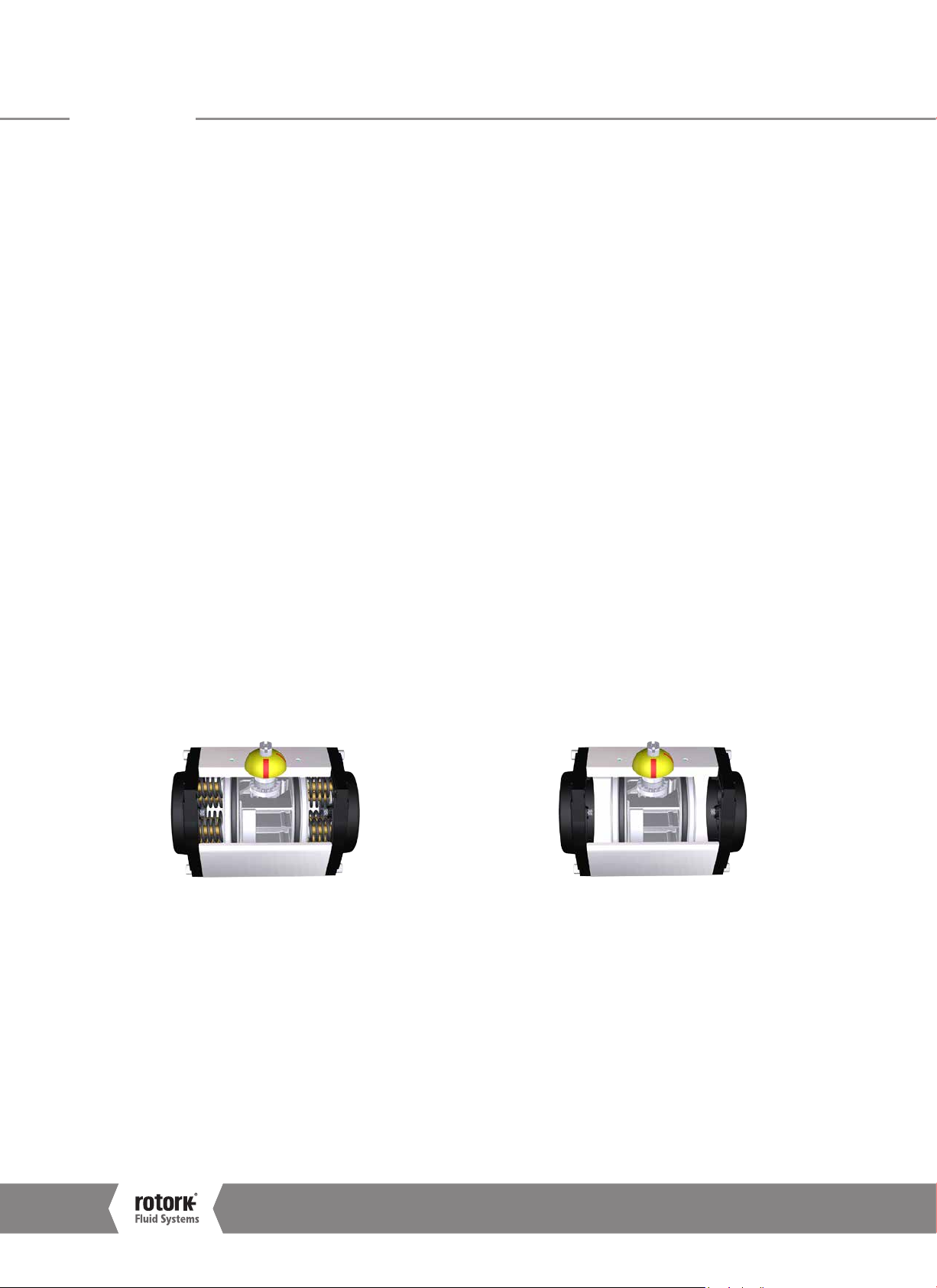
Single-acting actuator Double-acting actuator
This manual contains important safety information.
Please ensure it is throughly read and understood
before installing, operating or maintaining the
equipment.
Rotork Fluid Systems reserves the right to modify,
amend and improve this manual without notice.
2
Installation, Commissioning and Maintenance Manual
Due to wide variation in the terminal numbering of
actuator products, actual wiring of this device should
follow the print supplied with the unit.
Page 3
1.0 Introduction 2.0 Standards & Regulations
This manual covers maintenance aspects and instructions
specific to the GT range actuators. General information on
Rotork Fluid Systems actuators are described in the User
Manual, delivered separately.
In this manual, warning indications are represented by icons,
according to ISO 7010 Safety Signs:
Generic danger
Hand crush / pinch point
Electrocution
Explosive material
Customer Service
For technical assistance, please contact the
Rotork Fluid Systems Customer Service:
E-mail: rfs.internationalservice@rotork.com
Rotork Fluid Systems, Via Padre Jaques Hamel 138B,
Porcari, Lucca, IT. Tel: +39 0583-222-1
Rotork plc, Brassmill Lane, Bath, UK. Tel +44 (0)1225 733200
Actuators destined for European member states have been
designed, built and tested according to the Quality Control
System, in compliance with the EN ISO 9001:2015 standard
and with the following regulations/directives.
•
2006/42/EC: Machinery Directive
•
2014/34/EU: Directive for safety equipment and systems
to be used in potentially explosive atmospheres (ATEX)
•
ISO 80079-36: Non-electrical equipment for explosive
atmospheres – Basic method and requirements
•
ISO 80079-37: Non-electrical equipment for explosive
atmospheres – Non-electrical type of protection
construction safety "c", control of ignition sources "b",
liquid immersion "k".
Keeping the World Flowing
3
Page 4

3.0 General Information 4.0 Health & Safety
This manual is produced to enable a competent user to install,
operate and maintain the Rotork Fluid Systems GT Actuator
Single- and Double-Acting.
The mechanical installation should be carried out as outlined
in this manual and also in accordance with any relevant
national standard codes of practice.
Maintenance and operation should be carried out in
accordance with National Legislation and Statutory Provisions
relating to the safe use of this equipment, applicable to the
site of installation.
Any inspection or repair in a Hazardous Area should not be
undertaken unless it conforms to National Legislation and
Statutory Provisions relating to the specific Hazardous Area.
Only Rotork approved replacement parts should be used.
Under no circumstances should any modification or alteration
be carried out on the equipment, as this could invalidate the
conditions under which its certification was granted.
Only trained and experienced operators should be allowed
to install, maintain and repair Rotork Actuators. Work
undertaken must be carried out in accordance with
instructions in this manual. The user and those persons
working on this equipment should be familiar with their
responsibilities under any statutory provisions relating to the
Health and Safety of their workplace.
Operators should always wear appropriate Personal
Protection Devices (PPDs) in line with the existing plant
regulations.
Appropriate Usage
Rotork Fluid Systems GT actuators have been specifically
developed to motorize part turn valves, such as ball valves,
butterfly valves or plug valves installed on pipelines for oil &
gas transport and distribution.
Improper use can damage the equipment or cause
dangerous situations for health and safety. Rotork
Fluid Systems declines any responsibility for damage
to people and/or objects resulting from the use of
the equipment for applications different from those
described in the manual.
Before installing the equipment, verify it is suitable for the
intended application. If unsure consult Rotork Fluid Systems.
4.1 Residual Risks
Residual risks resulting from equipment risk evaluation
performed by Rotork Fluid Systems.
4.2 Thermal Risks
Risk Hot/Cold surface during normal
operation (RES_01).
Preventive measures
Operators should wear protective gloves.
4.3 Noise
Risk
Preventive measures Operators should wear ear protections.
Noise >85 dB during operation (RES_05).
Operators should not stand near the
equipment during operation.
4.4 Health Risks
Risk Pressurized fluid ejection during
normal operation (RES_02).
Preventive measures All fittings must be properly sealed.
All fixing clamps must be correctly
tightened and sealed.
Risk Risk of intoxication (according to the
type of medium utilized) (RES_06).
Preventive measures Operators must use P.P.Ds and any
other equipment (breathing apparatus)
based on the type of supply medium.
4.5 Mechanical Risks
Risk Uncontrolled movement (remote
operation) (RES_03) (This risk is
applicable only for actuators provided
with control panel).
Preventive measures Assure that the actuator cannot be
operated remotely. Prior to starting,
remove pneumatic supply, vent all
pressure vessels, and remove
electrical power.
Risk Presence of moving parts (center body,
valve adapter) (RES_04).
Preventive measures Do not perform start-up or test
the actuator if the cylinder tube is
removed.
4
Installation, Commissioning and Maintenance Manual
Page 5
4.0 Health & Safety
5.0 Labels & Nameplates
Risk Loss of stability with possible parts
projection (RES_08).
Preventive measures Do not disassemble the actuator
in case of malfunctioning. Follow
instructions in the manual and contact
Rotork Fluid Systems.
Preventive measures Foresee periodic maintenance
procedure to verify tightening.
Risk Presence of potential energy (RES_10)
during dismantling.
Preventive measures Do not disassemble the actuator
during dismantling. Follow instructions
in the manual and contact Rotork
Fluid Systems.
4.6 Magnetic Risks
Risk Risk of magnetic field/disturbance and
exothermic reactions.
Preventive measure The End User shall assure that actuator
and its components are installed
far from magnetic field, electromagnetic field, radioactive source,
electroacoustic transducer which could
modify its behaviour.
(This mitigation is applicable only for
actuators provided with control panel).
Avoid maintenance operations with
acid/basic solutions.
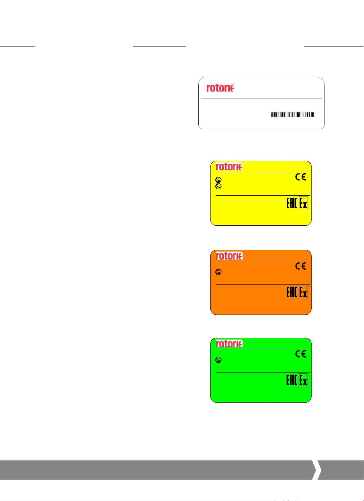
The following label is applied externally to the each Actuator:
Via Padre jacques Hamel, 138B
PORCARI, LUCCA 55016 - ITALY
Fluid Systems
PRODUCT
MAX PRESSURE : 1,0MPa/10bar/150Psi
MAX VOLUME dm :
Serial Number
Product of Italy
3
Tel: +00 (039) 0583 2221
MANUFACTURED 10/2017
Information: sales.lu cca@rotork.com
Fig 5.1 Actuator label
In case of ATEX and/or EAC certifications the following labels
with be also applied:
MODEL: GT / RCR - PNEUMATIC ACTUATOR
II 2 G Ex h IIC T5 Gb
II 2D Ex h IIIC T100°C Db
T. amb. -50 °C +70 °C
Модель: GT / RCR - пневматический привод
№ TC RU C-IT.ME92.B.00889
Серийный номер привода указан на корпусе привода
IIGb IIC T5 X
IIIDb IIIC T100°C X
Темп. окр. среды: -50 °C +70 °C
Fig 5.2 Actuator ATEX/EAC label for standard
MODEL: GT / RCR - PNEUMATIC ACTUATOR
T. amb. -15 °C +160 °C
Модель: GT / RCR - пневматический привод
№ TC RU C-IT.ME92.B.00889
Серийный номер привода указан на корпусе привода
IIGb IIC T3 X
Темп. окр. среды: -15 °C +160 °C
Fluid Systems
Tech-File--TR563-X/2017
Deposited in Cesi
0722
Тех. пакет: R563-X/2017
Депозитарий в
г. Чези, Италия:
temperature (-50°C<T<+70°C)
Fluid Systems
II 2G Ex h IIC T3 Gb
Tech-File--TR563-X/2017
Deposited in Cesi
0722
Тех. пакет: R563-X/2017
Депозитарий в
г. Чези, Италия:
0722
0722
Fig 5.3 Actuator ATEX/EAC label for high
temperature (-15°C<T<+160°C)
Fluid Systems
MODEL: GT / RCR - PNEUMATIC ACTUATOR
II 2G Ex h IIC T2 Gb
T. amb. -60 °C +200 °C
Модель: GT / RCR - пневматический привод
№ TC RU C-IT.ME92.B.00889
Серийный номер привода указан на корпусе привода
IIGb IIC T2 X
Темп. окр. среды: -60 °C +200 °C
Fig 5.4 Actuator ATEX/EAC label for low
temperature (-60°C<T<+200°C)
Label removal is not allowed.
Keeping the World Flowing
Tech-File--TR563-X/2017
Deposited in Cesi
0722
Тех. пакет: R563-X/2017
Депозитарий в
г. Чези, Италия:
0722
5
Page 6

6.0 Operating Limits
Temperature: -50 °C to +70 °C (-58 °F to +158 °F)
NBR o-ring, Delrin Guide
-15 °C to +160 °C (+5 °F to +320 °F)
Viton o-ring, IXEF Guide
-60 °C to +200 °C (-76 °F to +352 °F)
Silicon o-ring, PTFE Guide
Operating pressure: 2 to 10 bar (compressed air)
Operating pressure: 2 to 5 bar (methane, ethane,
propane, butane)
Do not use the equipment outside its operating limits.
It is critical that external surface temperature does not reach
or exceed the ignition temperature of potentially explosive
atmospheres when installed in these locations.
The actuator surface temperature is strictly dependent
on the temperature of the process fluid used and by the
irradiation’s conditions. The end-user has to check the surface
temperature of the assembly, so that this cannot exceed the
minimum gas ignition’s temperature, which classifies the area
with the explosion’s risk.
Dust and debris accumulated on the actuator will slow down
its cooling and contribute to the increase of its external
temperature.
6.3 Tightening Torque Chart
Actuator size
52 - 63 M5 8 2
75 - 83 - 92 M6 12 3
110 - 118 M8 15 4.5
127 M8 15 8
143 - 160 M10 20 8
190 - 210 M12 28 13
254 - 255 M14 40 20
300 M14 40 30
Screw
size
Torque
(Nm)
Stop nut
(Nm)
6.1 Allowed Fluid Types
GT pneumatic actuators are designed to be operated with
Gas, Instrument air filtered PNEUROP/ISO class 4; if not
differently specified in specific project documentation.
Do not use the actuator in presence of naked flames.
6.2 Expected Lifetime
Expected Lifetime greater than 25 years, in normal service
conditions and with planned maintenance.
6
Installation, Commissioning and Maintenance Manual
Page 7
7.0 Handling & Lifting
Only trained and experienced personnel should
handle/lift the actuator.
GT actuators are supplied packed in cardboard boxes suitable
for normal handling.
Handle the actuator with care.
7.1 Lifting Recommendations
•
The lifting device and the sling must be suitably rated for
the actuator weight and dimensions
•
Do not use damaged sling(s)
•
The sling must not be shortened with knots or bolts or
any other makeshift device
•
For lifting purposes, use only suitable lifting tools
•
Do not drill holes, weld eye bolts or add any other type of
lifting device on the actuator external surface
•
Do not lift the actuator and valve combination with the
actuator lifting lugs
•
Every assembly must be estimated separately for a safe
and correct lifting
•
Avoid pulls or abrupt movements during lifting. Avoid
pushing the load
•
During lifting operations, do not handle the slings and/or
the actuator
Do not step underneath suspended load.
7.2 Lifting Instructions
NOTE: Indication of weight, center of gravity,
lifting points are reported within project specific
documentation.
Consult project specific documentation before lifting.
•
Prior to lifting the actuator, remove electrical power and
vent all pressure vessels (if present)
•
Actuators up to size 160 can be manually lifted
•
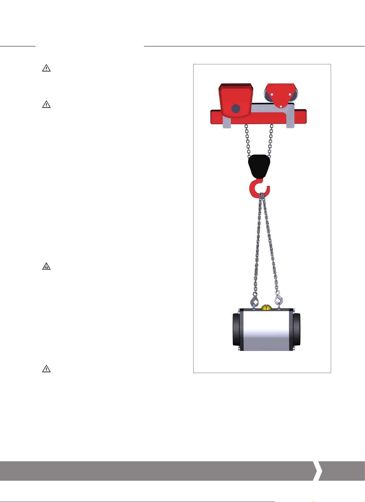
Actuators sizes from 190 to 302 must be lifted using the
lifting lugs to be installed on the top side of the actuator
The actuator must remain horizontal; balance the load.
•
Angle β must between 0° and 45° as shown opposite
β
Fig 7.1 Lifting (size 190)
Keeping the World Flowing
7
Page 8

8.0 Storage
9.0 Long Term Storage
Rotork Fluid Systems actuators have been fully tested before
leaving the factory.
In order to keep the actuator in good condition
until installation, at least the following measures are
recommended:
•
Check presence and assembling of dust plugs
•
Keep the actuator on shipping pallet until installation
Never put the actuator directly on the ground.
•
Actuator must be positioned upwards
•
Protect against adverse weather conditions, covering the
actuators with appropriate polyethylene sheets
•
Check the actuator condition every 6 months and verify
the above protection measures remain in place
Remove package only when required for
installation.
If long term storage is necessary, further operations must
be carried out to maintain the actuator in a good working
condition:
•
Storage should be indoors and the units should be
protected against humidity and other harmful elements
•
Replace the plastic plugs with metal plugs
•
Stroke the actuator every 12-months
•
Cycle the actuator (using filtered, dehydrated air) to the
working pressure indicated on the name plate
•
Cycle the actuator with all the existing controls
(i.e. two complete strokes - one open, one closed)
at least 5 times
•
Cycle the actuator fitted with the mechanical manual
override or hydraulic manual override by means of the
override for 4 complete strokes
•
Disconnect the pneumatic and electric (if present)
supply from the actuator, and carefully close all the
threaded connections of the actuator
•
Remove electrical component covers (if present) to ensure
control terminals are clean and free from oxidation and
humidity. Reassemble the covers
•
In case of storage for over 12 months prior to installation,
it is recommended to operate the actuator to verify
correct operation
8
Installation, Commissioning and Maintenance Manual
Page 9

10.0 Installation on Valve
Before proceeding, read and understand the Health and
Safety information.
Note: The valve should be properly secured prior to
performing the following operations according to
instructions provided by the Valve Manufacturer.
Prior to performing any operations check the
operating drawings and TAG numbers.
Consult Rotork Fluid Systems for any additional information.
10 .1 Preliminary Actions
Verify the Hazardous Area classification of the
actuator is compatible with the plant zoning. Refer to
actuator nameplate.
•
The centreline of the cylinder is usually aligned to the
centreline of the associated pipe work
•
Ensure all fasteners are adequately tightened to avoid
loosening during operation, taking into account the
vibrations induced by the dynamics of the pipeline
•
Piping used to provide power to the actuator must be
free from contaminants and debris. Ensure tubing runs
are adequately fastened and supported to minimize
repetitive stress induced by the dynamics of the pipeline.
Ensure there are no leaks from any gas connections.
Tighten as required
10.2 Instructions
Actuator to valve attachment can be performed by:
•
Mounting directly using the actuator housing bottom
flange drilling
•
Using an adapter and a coupling joint between the
actuator and the valve
Actuator bottom flange drilling is in accordance to ISO 5211
(DIN 3337) standard.
The assembly position of the actuator must be in accordance
with the actuator design, plant requirements and the valve
model. In order to assemble the actuator onto the valve,
proceed as follows:
•
Verify the coupling dimensions of the valve flange and
stem; they must meet the actuator coupling dimensions
(refer to PUB110-001 for metric and PUB110-002 for
imperial)
•
Actuator is supplied in the fail position (for single-acting).
Set the valve in the right position according to the
actuator fail position. Check the position of the actuator
by means of the position indicator on the body or on the
limit switch box (if present)
•
Clean the coupling flange of the valve and remove
anything that might prevent adherence to the actuator
flange. Grease shall be completely removed
•
Inspect, clean and apply grease on the coupling hole
(valve side of coupling joint)
•
Lubricate the valve stem with oil or grease, to facilitate
assembling
Lift the actuator according to instructions in section 7.0.
•
If possible, place the valve stem in a vertical position
to facilitate assembly – in this case the actuator must
be lifted while the coupling flange is kept in the
horizontal position
•
If a direct mounting is applied, insert the valve stem
directly into the actuator pinion
•
If the assembly uses an adapter and a coupling joint,
assemble the coupling joint onto the valve stem before
proceeding with mounting of the actuator
•
Do not exert any force while lowering the actuator
onto the valve
Installation must be performed by qualified personnel.
Hands must be kept away from the coupling area.
Fig 10.1 Actuator bottom connections
Each pinion, as standard, is provided with a female key ISO
5211 double square, allowing direct mating to the valve stem,
or coupling.
Optional valve interfaces are ISO 5211 single square parallel,
ISO 5211 single square diagonal and double D.
•
Fix the actuator to the valve by means of threaded
connections (bolts, stud bolts and nuts)
•
Tighten bolts or nuts of the connecting stud bolts to the
correct torque, in accordance with the size and material
characteristics of the bolts installed by the Customer,
please refer to the Tightening Torque Chart, section 6.3
Support the actuator until fully installed and fixing
bolts are correctly tightened.
Attention: Do not pressurize the actuator/
valve adapter.
Keeping the World Flowing
9
Page 10
10.0 Installation on Valve 11.0 Removal from Valve
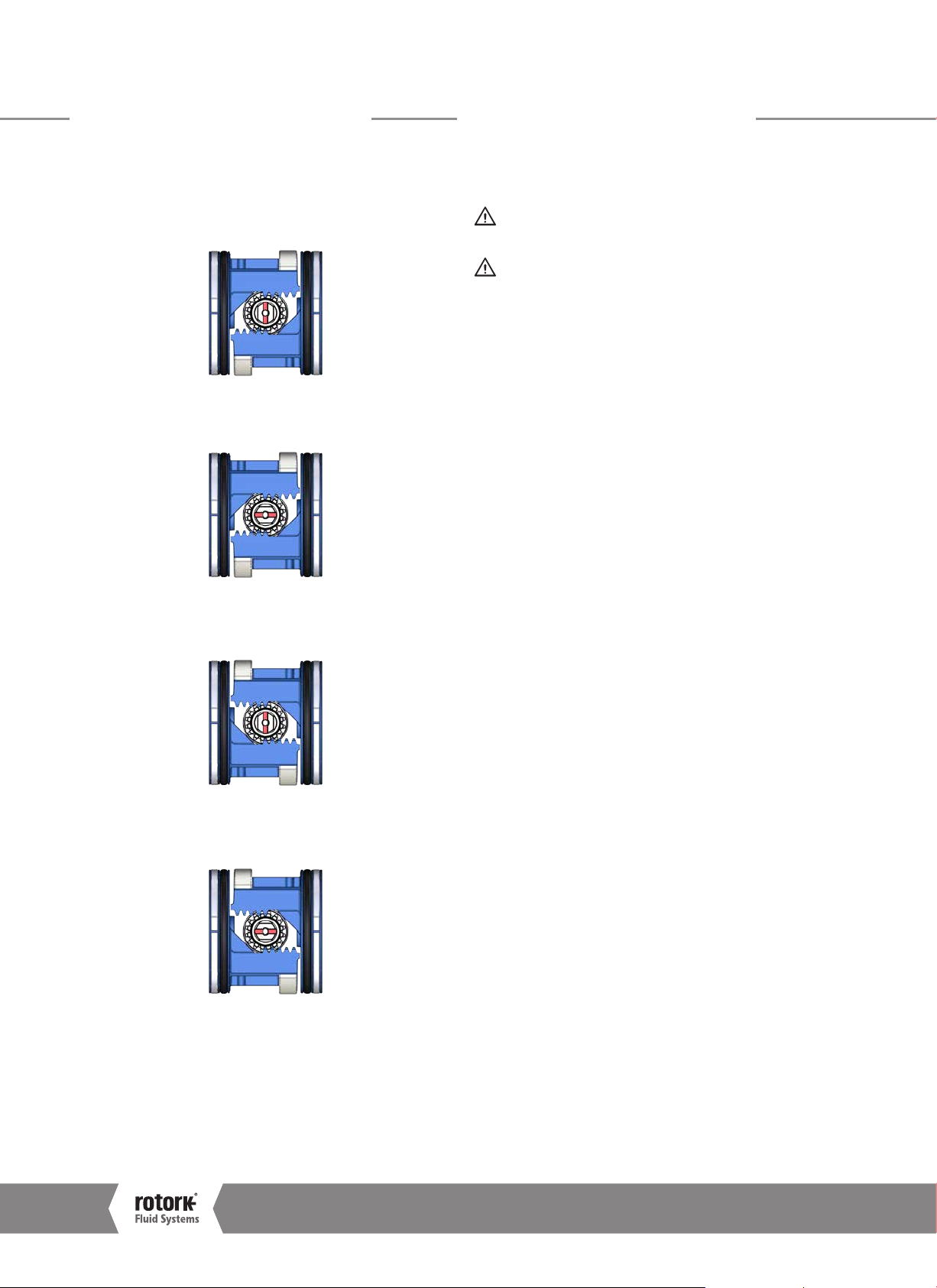
10.3 Assembly Configurations
Different orientations of pinion and pistons are identified
as follows:
Fig 10.2 A ssembly A – Clock wise to close actuators,
upper shaft perpendicular to body
Fig 10.3 A ssembly B – Clock wise to close actuators,
upper shaft parallel to body
The end user is in charge of removing the actuator
from the valve.
Removal shall be performed only by qualified staff,
wearing/using appropriate personal protection devices.
Do not remove the actuator if the valve is blocked in
the intermediate position. Contact Rotork Fluid Systems
Customer Service.
In order to disassemble the actuator from the valve, proceed
as follows:
•
Isolate electrical power supply
•
Isolate pneumatic /hydraulic supply
•
Release any pressure from the control group
•
Remove the supply pipes from the actuator
•
Remove control and signal lines from electric components
(if any)
•
Sling the actuator in line with the instructions given in
section 7.0
•
Unscrew bolts or nuts from the stud bolts fixing the
actuator to the valve
•
Lift and remove the actuator from the valve
Fig 10.4 A ssembly C – Counter-clockwise to close
Fig 10.5 A ssembly D – Counter-clockwise to close
10
actuators, upper shaft perpendicular to body
actuators, upper shaf t parallel to body
Installation, Commissioning and Maintenance Manual
Page 11
12.0 Operation
The following instructions must be followed and integrated
into end user safety program when installing and using
Rotork products. Read and save all instructions prior to
installing, operating and servicing this product.
Follow all warnings, cautions and instructions marked on and
supplied with the product.
Install equipment as specified in Rotork installation
instructions and as per applicable local and national
codes of practice. Connect all products to the proper
pipeline gas sources.
Ensure that the qualified service technician uses only
replacement parts specified by Rotork.
Substitutions will invalidate any hazardous area certification
and may result in fire, electrical shock, other hazards or
improper operation.
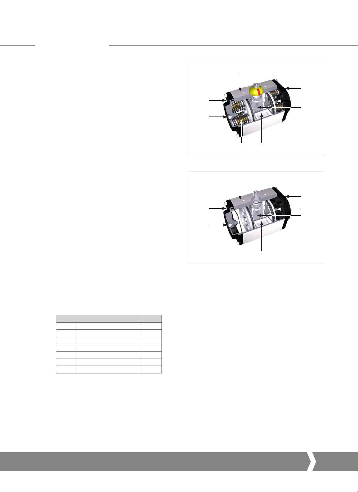
12 .1 Description
GT range actuators are a rack and pinion design, available
in both double-acting and single-acting (spring-return)
configurations.
The rack and pinion design assures constant torque, strength
and reduced overall dimensions. All double-acting actuators
can be easily field converted to spring-return type by inserting
the correct number of spring cartridges to the double-acting
unit without changing the existing end caps. This eliminates
bulky housing extensions and saves weight and space.
For 90° execution, specially designed and patented preloaded
self-containing spring cartridges are completely contained
assuring safe installation and removal. For 120°-180° action
the springs are free.
Standard action is 90°, 120°, 135°, 180° and 240°.
Customised angles are available, as well as three position
versions.
2
3
1
56
Fig 12.1 GT spring-return main components
2
3
1
5
Fig 12.2 GT double-acting main components
3
7
4
3
7
4
Table 1: GT double-ac ting main components
IT DESCRIPTION QTY
1 Mechanical stop bolt 1
2 Body 1
3 End cap 2
4 Pinion 1
5 Rack 2
6 Spring cartridge *
7 Mechanical stop bolt 1
(*) Model dependant
Keeping the World Flowing
11
Page 12

12.0 Operation
12.2 Single and Double Limit Stop
GT Actuators can be provided in 2 versions: single and double
limit stop.
The
single limit stop
stop bolts installed in the end caps and allows adjustment
of the open stroke of a clockwise to close (close stroke of an
anti-clockwise to close) actuator. Adjustability is ±5°.
The
double limit stop
mechanical stop bolts installed in the end caps and allows
the adjustment of both travel directions. Adjustability is
±5° on the open stroke of a clockwise to close (close stroke
of an anticlockwise to close) actuator and -25°/+5° on the
close stroke of a clockwise to close (open stroke of an
anticlockwise to close) actuator.
is provided with 2 identical mechanical
is provided with 2 different
Fig 12.3 Single limit stop
Fig 12.4 Double limit stop
12
Installation, Commissioning and Maintenance Manual
Page 13

12.0 Operation
12.3 Angular Stroke Setting
Single and double-acting actuator, cylinder stop
bolt setting
Perform the following operations as first setting.
Adjust the stop bolt located in the end flange of the
cylinder as follows:
1
A. Verify the absence of pressure
B. Loosen stop nut (1) with a suitable spanner
2
C. With the help of a suitable size Allen (hex.) Key, rotate
the stop bolt (2) clockwise to increase (counter-clockwise
to decrease) the angular stoke
Verify the newly obtained angular position with one stroke
D. Repeat operations A to D, until the desired angle
is obtained
1
2
E. Hold the stop bolt (2) with a Allen (hex.) key and carefully
tighten the stop nut (1)
G: Repeat the operation for the other stop bolt
The above procedure applies to both single limit stop
and double limit stop.
In case of double limit stop, before starting
the procedure to adjust the stop bolt for -25°/+5°
(identifiable from the bronze colour stop nut), make
sure the stop bolt is not against the pinion to avoid a
stick slip movement.
Keeping the World Flowing
13
Page 14

12.0 Operation
12.4 Pneumatic Supply
Verify allowed supply pressure range on actuator label.
Verify medium composition. Contact Rotork Fluid
Systems to check the compatibility with the supply
medium.
12.5 Pneumatic Connections
Preliminary Operations
A. Verify sizes of pipes and fittings according to applicable
plant specifications
B. Clean the inside of the connection pipes by washing them
with a suitable detergent and by blowing air into them
C. The connecting pipes must be properly shaped and fixed
to prevent stress or loosening of threaded connections
Connect the pneumatic source in accordance to the
applicable operating diagram, please refer to specific
job for details.
Depending upon the control circuit design,
pneumatic actuators may exhaust the supply gas into
the atmosphere during normal operation. This may
present an unacceptable hazard.
Port 2 is connected to the inboard side of the pistons.
Port 4 is connected to the outboard side of the pistons.
Port 4
Port 2
Fig 12.5 Inlet port for Single-Acting actuator
Port 4
Port 2
Fig 12.6 Inlet / Exhaust port for Double-Acting actuator
Single-Acting actuators
Pressurising port 2 will move the pistons out. When port 2 is
depressurised, spring force will move the pistons in. Venting
is through port 2. Port 4 is not to be pressurised on springreturn actuators.
Double-Acting actuators
Pressurising port 2 will force the pistons out until they reach
the travel stops. Venting is through port 4.
Pressurising port 4 will force the pistons in until they reach
the travel stops (if fitted). Venting is through port 2.
The direction of pinion rotation is determined by the
assembly configuration described in section 10.3.
14
Installation, Commissioning and Maintenance Manual
Page 15

12.0 Operation
12.6 Electrical Connections
Check electrical component supply voltage,
before start-up.
Access to live electrical conductors is forbidden in
hazardous areas unless done under a special permit.
Otherwise, all power should be isolated and the unit
moved to a non-hazardous area for repair.
Prevent electrostatic charges in potentially
explosive areas.
Electrical connection can be performed as follows:
•
Remove power supply
•
Remove the plastic protection plugs from the cable
entries
•
Use only appropriately certified reduction fittings, cable
glands, fittings and explosion-proof cables
•
The cable glands must be tightened in the threaded
inlets, to guarantee the waterproof and explosion proof
protection
•
Cable gland sealing should be installed correctly to
prevent water or debris ingress to the electrical enclosure
•
The size of the electric supply cable must be suitable for
the electrical power required
•
Insert the connection cables through cable glands
and perform assembly according to the cable gland
manufacturer’s instructions
•
Connect the cable wires to the terminal blocks in
accordance with the applicable wiring diagram
•
Electric connections must be made by using rigid conduits
and trailing cables to prevent mechanical stresses in the
cable entries
•
Unused entries must have metal blanking plugs installed
in order to guarantee sealing and to comply with
explosion safety protection codes
•
Assemble the covers of the electric components, paying
attention to seals
•
Once connections have been completed, check electrical
components functionality
12.7 Start Up
During start-up of the actuator, it is necessary to check if:
•
Medium supply pressure is as prescribed
•
The power supply to electrical components (solenoid
valves coils, limit switches, pressure switches, etc.) are
within specification
•
Actuator controls such as remote control, local control,
emergency control, etc. work properly
•
Input remote signals are correct
•
The setting of control unit components is according to the
plant requirements
•
Pneumatic connections show no leakage. If necessary,
tighten fittings or adjust sealing
•
The painted parts have not been damaged during
transport, assembly or storage operations. Otherwise
adequately repair the damaged parts following the
applicable painting specifications
•
Actuator and all additional equipment work as expected
•
Operating time is in accordance with requirements
The end user must guarantee equal voltage
potential between the valve and the actuator and
provide appropriate grounding. End user shall
indicate and maintain the grounding connections
on the actuator.
Actuator and electrical components must be
protected from electrical sparks, lightning, magnetic or
electro-magnetic fields.
Keeping the World Flowing
15
Page 16

13.0 Dismantling & Disposal 14.0 Rotork Sales and Service
Prior to dismounting the actuator, ensure no parts are still
under pressure.
For Single-Acting Actuator
The spring cartridge module contains potential
energy due to compressed elastic elements.
After removing the spring cartridge from the center body,
the spring cartridge must be returned to the manufacturer’s
plant, upon agreement with Rotork Fluid System.
Grease and oil must be disposed of safely in
accordance with the local environmental laws and
regulations.
•
Dismount the actuator, separate and divide the various
components according to the type of material
•
Dispose steel, cast iron and aluminium alloy components
as metal scraps
•
Dispose rubber, PVC, resins, etc. separately, in accordance
with national and regional regulations
•
Electrical components are to be separately disposed of on
specialized disposal sites
If your Rotork actuator has been correctly installed and
sealed, it will give years of trouble-free service. Should you
require technical assistance or spares, Rotork guarantees
the best service in the world. Contact your local Rotork
representative or the factory direct at the address on the
nameplate, quoting the actuator type and serial number.
Some actuators have a special spare parts list. Refer to the
project specific documentation for further details.
16
Installation, Commissioning and Maintenance Manual
Page 17

15.0 Troubleshooting
ID FAILURE POSSIBLE CAUSES CORRECTIVE MEASURES
1 Incorrect valve position •
2 Incorrect indication of valve position •
3 Incorrect movement
4 Valve stroke not fully completed
5 Leakages
6 Actuator moves too fast
7 Actuator moves too slow
8 Loss of power
Fault of pipeline valve
Incorrect signal from limit switches
•
Irregular supply of operating medium
•
Worn parts
•
Fault in control panel equipment
(if present)
•
Fault of pipeline valve
•
Insufficient gas flow
•
Incorrect assembly between actuator
and valve
•
Valve blocked
•
Stop bolts wrong setting
•
Stop bolts wrong setting
•
Worn seals
•
No pressure on pipeline
•
Supply pressure greater than allowed
range values
•
Fault on pipeline valve (valve hardened)
•
Supply pressure lower than allowed
range values
•
Possible internal undue friction
•
Inadequate supply pressure
•
Leakage from cylinder
•
Consult the valve manufacture’s documentation
•
Check limit switches position (see job
specific documentation and limit switch box
manufacturer’s documentation)
•
Verify the supply pressure and adjust as
necessar y
•
Contact Rotork Fluid Systems
•
Contact Rotork Fluid Systems Customer Service
•
Consult the valve manufacture’s documentation
•
Increase gas supply flow
•
Perform assembly according to section 10.0
•
Consult the valve manufacture’s documentation
•
Adjust stop bolt setting following instructions in
section 12.3
•
Adjust stop bolt setting following instructions in
section 12.3
•
Replace seals according instructions reported in
PM-GT-005/006
•
Restore pipeline pressure
•
Verify the supply pressure and adjust as
necessar y
•
Consult the valve manufacture’s documentation
•
Verify the supply pressure and adjust as
necessar y
•
Contact Rotork Fluid Systems Customer Service
•
Ensure that the supply pressure is above the
minimum operating pressure of the actuator
and that the output torque produced at supply
pressure exceeds the required valve torque
•
Replace seals according instructions reported in
PM-GT-005/006
For other problems, please contact Rotork Fluid Systems Customer Service.
Keeping the World Flowing
17
Page 18

16.0 Periodic Maintenance
Rotork Fluid Systems recommends performing the following checks to help comply with the rules and regulations
of the country of final installation:
Remove pressure before proceeding with maintenance operations, discharge any accumulators
or tanks (if present), except where otherwise indicated.
Periodic Maintenance Schedule
MAINTENANCE ACTIVITY PERIODICITY REFERENCE
Months Years
Visual check of external components and control groups 6* *
Breather cleaning 6* *
Check pneumatic connections for leaks. Tighten pipe fittings as required - 1*
Cleaning - 1* PM-GT-001
Visual check of paint coating. Verify absence of damage. Repair if necessary
according to painting specification
Functional test - 1* PM-GT-002
Functional test by Manual Override - 1*
Check electrical components (if applicable) and grounding connections - 1* PM-GT-004
Check threaded connections (bolts, studs and nuts) with valve. If necessary
tighten to the recommended torque, in accordance with the size and the
characteristics of the fastener material installed by the Customer
Single stop actuator pneumatic cylinder seals replacement
(Spring-Return and Double-Acting Actuator)
Double stop actuator pneumatic cylinder seals replacement
(Spring-Return and Double-Acting Actuator)
(*) The time between maintenance tasks will vary depending on the medium and service conditions. Refer to End User Plant Preventive Maintenance
Program for specific task frequenc y.
- 1*
1*
- 5* PM-GT-005
- 5* PM-GT-006
Corrective Maintenance Task
In case of fault, according to section 15.0, the following operations could be executed by the End User.
MAINTENANCE ACTIVITY REFERENCE
Single limit stop actuator fail mode converting CM-GT-001
Double limit stop actuator fail mode converting CM-GT-002
18
Installation, Commissioning and Maintenance Manual
Page 19

16.0 Periodic Maintenance
Component: Single-Acting actuator
Double-Acting actuator
PM-GT-001 Page:1/1
Task: Cleaning
Equipment, Tools, Materials:
Damp cloth
Project documentation (design and operating pressure values)
Preliminary Operations:
Description:
Remove electric and pneumatic supply before proceeding.
1. Remove dust from actuator external surface with a damp cloth
The tools and cleaning procedures must not produce sparks or create adverse conditions in the environment during maintenance
operations, so as to prevent potential explosion hazards.
Prevent electrostatic charges in potentially explosive areas.
Warnings:
Keeping the World Flowing
19
Page 20

16.0 Periodic Maintenance
Component: Single-Acting actuator
Double-Acting actuator
PM-GT-002 Page:1/1
Task: Functional test
Equipment, Tools, Materials:
Chronometer/timer
Project documentation (required stroke times)
Preliminary Operations:
Description:
NOTE: Actuator must be connected to the pneumatic supply to perform the following test.
1. Operate the actuator
2. Perform the stroke several times by local and remote (if applicable) control
Actuator could exhaust medium supply to the atmosphere during normal operation.
Wear appropriate PPD including breathing device.
3. Verify actuator is correctly working
4. Note the stroke time(s)
5. Verify stroke time(s) are as required
Warnings:
20
Installation, Commissioning and Maintenance Manual
Page 21

16.0 Periodic Maintenance
PM-GT-004 Page:1/1
Component: Electrical components (if present) Task: Check electrical components (if present) and grounding
connections
Equipment, Tools, Materials:
Project documentation
Preliminary Operations:
Description:
Isolate electrical power supply before working on electrical devices.
Read and follow the safety precautions reported in the Manufacturer’s Maintenance Manual.
Risk of temporary modification of the component protection.
Use only antistatic clothes.
1. Remove cover from electric components
2. Check electric device components
3. Verify tightness of terminal blocks
4. Verify absence of humidity and oxidation
5. Check cable gland seals
6. Verify grounding connection and restore if necessary
Warnings:
Keeping the World Flowing
21
Page 22

16.0 Periodic Maintenance
Component: Single limit stop actuator pneumatic cylinder seals
replacement (Spring-Return and Double-Acting Actuator)
PM-GT-005 Page:1/2
Task: Pneumatic cylinder seals replacement
Equipment, Tools, Materials:
Spare seals
Wrench
Lifting tools
Project documentation
Preliminary Operations: Removal from Valve
Description:
Note: the following instructions apply both to Single-Acting and Double-Acting actuators unless otherwise specified.
Isolate pneumatic and electrical supply (if present) before performing any operation.
Preliminary actions
1. Remove any pressure
2. Remove electric supply
3. Remove actuator from valve
4. Position the actuator on a workbench (if possible) or in a stable position in a clean and closed area
5. Remove any control equipment (if present). Refer to the project specific documentation
6. Remove pneumatic pipes
7. With an Allen (hex.) key remove the 4 screws (1) from the
end cap (2)
8. Remove end caps (2)
9. Remove springs (3), if present
Warnings:
1
2
10. With the help of a Key-wrench, rotate the pinion shaft (4)
to extrude the 2 pistons (5)
23
45 5
22
Installation, Commissioning and Maintenance Manual
Page 23

16.0 Periodic Maintenance
Component: Single limit stop actuator pneumatic cylinder seals
replacement (Spring-Return and Double-Acting Actuator)
PM-GT-005 Page:2/2
Task: Pneumatic cylinder seals replacement
Equipment, Tools, Materials:
Spare seals
Wrench
Lifting tools
Project documentation
Preliminary Operations: Removal from Valve
11. Remove o-ring (7) and guide belt (8)
12. Remove sliding guide (9)
13. Carefully clean piston (5) o-ring grooves and all sealing surfaces
14. Replace o-rings (7) and lubricate with a grease layer
15. Replace guide belt (8) and sliding guide (9)
16. Repeat operations 11 to 15 for the other piston (5)
Warnings:
9
8 7
95
17. Reinstall pistons (5) – be careful to respect 0° position and
fail action
18. Reinstall (3) springs, if present
19. Reinstall end caps (2) and tighten screws (1) – refer to
section 6.3
8 7
45 5
1
2
23
Keeping the World Flowing
23
Page 24

16.0 Periodic Maintenance
Component: Double limit stop actuator pneumatic cylinder seals
replacement (Spring-Return and Double-Acting Actuator)
PM-GT-006 Page:1/4
Task: Pneumatic cylinder seals replacement
Equipment, Tools, Materials:
Spare seals
Wrench
Lifting tools
Project documentation
Preliminary Operations: Removal from Valve
Description:
Note: the following instructions apply both to Single-Acting and Double-Acting actuators unless otherwise specified.
Isolate pneumatic and electrical supply (if present) before performing any operation.
Preliminary actions
1. Remove any pressure
2. Remove electric supply
3. Remove actuator from valve
4. Position the actuator on a workbench (if possible) or in a stable position in a clean and closed area
5. Remove any control equipment (if present). Refer to the project specific documentation
6. Remove pneumatic pipes
7. With an Allen (hex.) key remove the 4 screws (1) from the
end cap (2)
8. Remove end cap (2)
9. Remove springs (3), if present
Warnings:
1
2
10. With an Allen (hex.) key remove the 4 screws (1) from the
other end cap (2)
3
1
2
24
Installation, Commissioning and Maintenance Manual
Page 25

16.0 Periodic Maintenance
Component: Double limit stop actuator pneumatic cylinder seals
replacement (Spring-Return and Double-Acting Actuator)
PM-GT-006 Page:2/4
Task: Pneumatic cylinder seals replacement
Equipment, Tools, Materials:
Spare seals
Wrench
Lifting tools
Project documentation
Preliminary Operations: Removal from Valve
11. Loosen the nut (10) with a socket wrench, remove washer (12)
and o-ring (11)
12. Using an Allen (hex.) key rotate the stop bolt (13) clockwise
all the way in
13. Remove the end cap (2)
14. Remove the springs (3), if present
Warnings:
111312 10
3 2
15. With the help of a Key-wrench, rotate the pinion shaft (4)
to extrude the 2 pistons (5) and (6)
45 6
Keeping the World Flowing
25
Page 26

16.0 Periodic Maintenance
Component: Double limit stop actuator pneumatic cylinder seals
replacement (Spring-Return and Double-Acting Actuator)
PM-GT-006 Page:3/4
Task: Pneumatic cylinder seals replacement
Equipment, Tools, Materials:
Spare seals
Wrench
Lifting tools
Project documentation
Preliminary Operations: Removal from Valve
16. Remove o-ring (7) and guide belt (8)
17. Remove sliding guide (9)
18. Carefully clean pistons (5) o-ring grooves and all sealing surfaces
19. Replace o-rings (7) and lubricate with a grease layer
20. Replace guide belt (8) and sliding guide (9)
21. Repeat operations 11 to 15 for the other piston (6)
Warnings:
9
8 7
95
22. Remove stop bolt (13) from piston (6)
23. Remove o-ring (6)
24. Clean the o-ring (6) groove
25. Replace o-ring (6) and lubricate with a grease layer
26. Pull stop bolt (13) back in place
27. Reinstall pistons (5) and (6) – be careful to respect
0° position and fail action
8 7
13
6
6
45 6
26
Installation, Commissioning and Maintenance Manual
Page 27

16.0 Periodic Maintenance
Component: Double limit stop actuator pneumatic cylinder seals
replacement (Spring-Return and Double-Acting Actuator)
PM-GT-006 Page:4/4
Task: Pneumatic cylinder seals replacement
Equipment, Tools, Materials:
Spare seals
Wrench
Lifting tools
Project documentation
Preliminary Operations: Removal from Valve
28. Reinstall (3) springs, if present
29. Reinstall end cap (2) and tighten screws (1) –
refer to section 6.3
30. Reinstall (3) springs, if present
31. Insert the end cap (2)
Warnings:
1
2
3
3 2
32. Using an Allen (hex.) key rotate the stop bolt (13) anti-clockwise
all the way back
33. Replace o-ring (11)
34. Reinstall washer (12)
35. Fasten the nut (10) with a socket wrench
36. With an Allen (hex.) key fasten the 4 screws (1) in the
end cap (2)
111312 10
1
2
Keeping the World Flowing
27
Page 28

16.0 Periodic Maintenance
CM-GT-001 Page:1/1
Component: Single limit stop Spring-Return and Double-Acting actuator Task: Fail mode converting
Equipment, Tools, Materials:
Wrench
Lifting tools
Project documentation
Preliminary Operations: Removal from Valve
1. With an Allen (hex.) key remove the 4 screws (1) from the
end cap (2)
2. Remove end cap (2)
3. Remove springs (3), if present
4. Turn the shaft (4) to help removal of the pistons (5)
5. Rotate pistons 180°
Warnings:
1
2
23
45 5
6. Reinstall pistons, be careful to perfectly match the pinion tooth
to keep the original pinion position
8. Reinstall (3) springs, if present
9. Reinstall end cap (2) and tighten screws (1) –
refer to section 6.3
410 10
1
2
23
28
Installation, Commissioning and Maintenance Manual
Page 29

16.0 Periodic Maintenance
Component: Double limit stop Spring-Return and Double-Acting
actuator
CM-GT-002 Page:1/3
Task: Fail mode converting
Equipment, Tools, Materials:
Wrench
Lifting tools
Project documentation
Preliminary Operations: Removal from Valve
1. With an Allen (hex.) key remove the 4 screws (1) from the
end cap (2)
2. Remove end cap (2)
3. Remove springs (3), if present
4. With an Allen (hex.) key remove the 4 screws (1) from the
other end cap (2)
Warnings:
1
2
23
1
5. Loosen the nut (10) with a socket wrench, remove washer (11)
and o-ring (12)
6. Using an Allen (hex.) key rotate the stop bolt (13) clockwise all
the way in
2
111312 10
Keeping the World Flowing
29
Page 30

16.0 Periodic Maintenance
Component: Double limit stop Spring-Return and Double-Acting
actuator
CM-GT-002 Page:2/3
Task: Fail mode converting
Equipment, Tools, Materials:
Wrench
Lifting tools
Project documentation
Preliminary Operations: Removal from Valve
7. Remove the end cap (2)
8. Remove the springs (3), if present
9. Turn the shaft (4) to help removal of pistons (5)
10. Rotate pistons 180°
Warnings:
3 2
45 5
11. Reinstall pistons, be careful to perfectly match the pinion tooth
to keep the original pinion position.
45 5
30
Installation, Commissioning and Maintenance Manual
Page 31

16.0 Periodic Maintenance
Component: Double limit stop Spring-Return and Double-Acting
actuator
CM-GT-002 Page:3/3
Task: Fail mode converting
Equipment, Tools, Materials:
Wrench
Lifting tools
Project documentation
Preliminary Operations: Removal from Valve
12. Reinstall (3) springs, if present
13. Reinstall end cap (2) and tighten screws (1) –
refer to section 6.3
14. Reinstall (3) springs, if present
15. Insert the end cap (2)
Warnings:
1
2
3
3 2
16. Using an Allen (hex.) key rotate the stop bolt (13) anti-clockwise
all the way back
17. Replace o-ring (12)
18. Reinstall washer (11)
19. Fasten the nut (10) with a socket wrench
20. With an Allen (hex.) key fasten the 4 screws (1) in the
end cap (2)
111312 10
1
2
Keeping the World Flowing
31
Page 32

17.0 Part List
Single Stop Actuator
Fig 17.1 Single Stop Actuator
ITEM DESCRIPTION QTY ITEM DESCRIPTION QTY
1 Piston guide belt
2 Pinion upper washer 1 22 Circlip 1
6 Pinion upper bearing 1 23 Nut 2
8 Pinion bottom washer 2 25 Stop bolt o-ring
9 Piston sliding guide
10 Position indicator 1 28 Bottom pinion o-ring
13 Anti-blow-out ring 1 29 Piston o-ring
15 Pistons 2 30 Washer 2
16 Actuator body 1 31 End cap o-ring
17 Pinion 1 33 Stop bolt 2
20 Body end caps 2 34 Screws 8
● Recommended spare par t
●
●
2 21 Spring cartridge
2 27 Upper pinion o-ring
●
●
●
●
●
2
1
1
2
2
32
Installation, Commissioning and Maintenance Manual
Page 33

17.0 Part List
Double Stop Actuator
Fig 17.2 Double Stop Actuator
ITEM DESCRIPTION QTY ITEM DESCRIPTION QTY
1 Piston Guide Belt
2 Pinion upper washer 1 21 Spring cartridge Model
6 Pinion upper bearing 1 22 Circlip 1
7 Guiding bush 1 23 Nut 2
8 Pinion bottom washer 2 25 Stop bolt o-ring
9 Piston sliding guide
10 Position indicator 1 27 Upper pinion o-ring
13 Anti-blow-out ring 1 28 Bottom pinion o-ring
14 Stop bolt 1 29 Piston o-ring
15 Pistons 2 30 Washer 2
16 Actuator body 1 31 End cap o-ring
17 Pinion 1 33 Stop bolt 2
18 Washer 1 34 Screws 8
● Recommended spare part
●
●
2 20 Body end caps 2
dependant
●
2 26 O-ring
●
●
●
●
●
2
1
1
1
2
2
Keeping the World Flowing
33
Page 34

18.0 Grease Specification
In general, there is no need to lubricate the actuator because
its mechanism is lubricated for life. The standard grease for
Rotork Fluid Systems GT actuators is shown below. If an
alternative was specified and/or supplied, please refer to the
job specific documentation.
18 .1 Grease
Lubricate mechanical components and cylinders of actuators
using the following grease or equivalent for temperature
range -50° < T < +140 °C.
Manufacturer: BECHEM Lubrication Technology
Trade name: BERULUBE FR 16
Colour:
Base OIl
Solid Lubricant
Thickener
Worked penetration (ISO 2137):
Viscosity of oil at 40 °C (104 °F) (DIN 51 562):
Service temperature:
Drop point (IP 396):
Corrosion test on Copper (24h\100 °C) 1 (DIN51 881)
Oxidation stability (100h\99 °C) 0.2 bar (DIN51 805)
Beige
Polyalphaolefin
Microfine PTFE powder
Special lithium soap
265-295 mm/10
32 mm2/s
-50 to 140 °C (-58 to 284 °F)
≥190
34
Installation, Commissioning and Maintenance Manual
Page 35

Keeping the World Flowing
35
Page 36

www.rotork.com
A full listing of our worldwide sales and
service network is available on our website.
Rotork plc
Brassmill Lane, Bath, UK
tel +44 (0)1225 733200
fax +44 (0)1225 333467
email mail@rotork.com
PUB110-009-00
Issue 0 4/18
Rotork is a corporate
member of the Institute
of Asset Management
All Rotork F luid Systems a ctuator s are manufac tured unde r a third par ty accredi ted ISO9 001 qualit y
assurance p rogramme. A s we are contin ually devel oping our pr oducts , their des ign is subjec t to change
without notice.
The name Rot ork is a regis tered trade mark. Rotor k recognis es all regis tered trade marks. Pu blished an d
produced i n the UK by Rotor k Fluid Syste ms. POW TG0518
 Loading...