

rotork CVL 500, CVL 1500, CVQ 1200, CVQ 2400 Installation And Maintenance Instructions Manual
Page 1
Electric Actuators and Control Systems
Established Leaders in Valve Actuation
This Manual contains important safety
information. Please ensure it is thoroughly read
and understood before installing, operating or
maintaining the equipment.
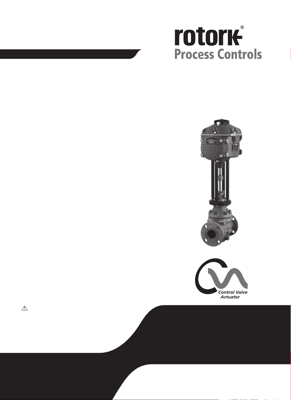
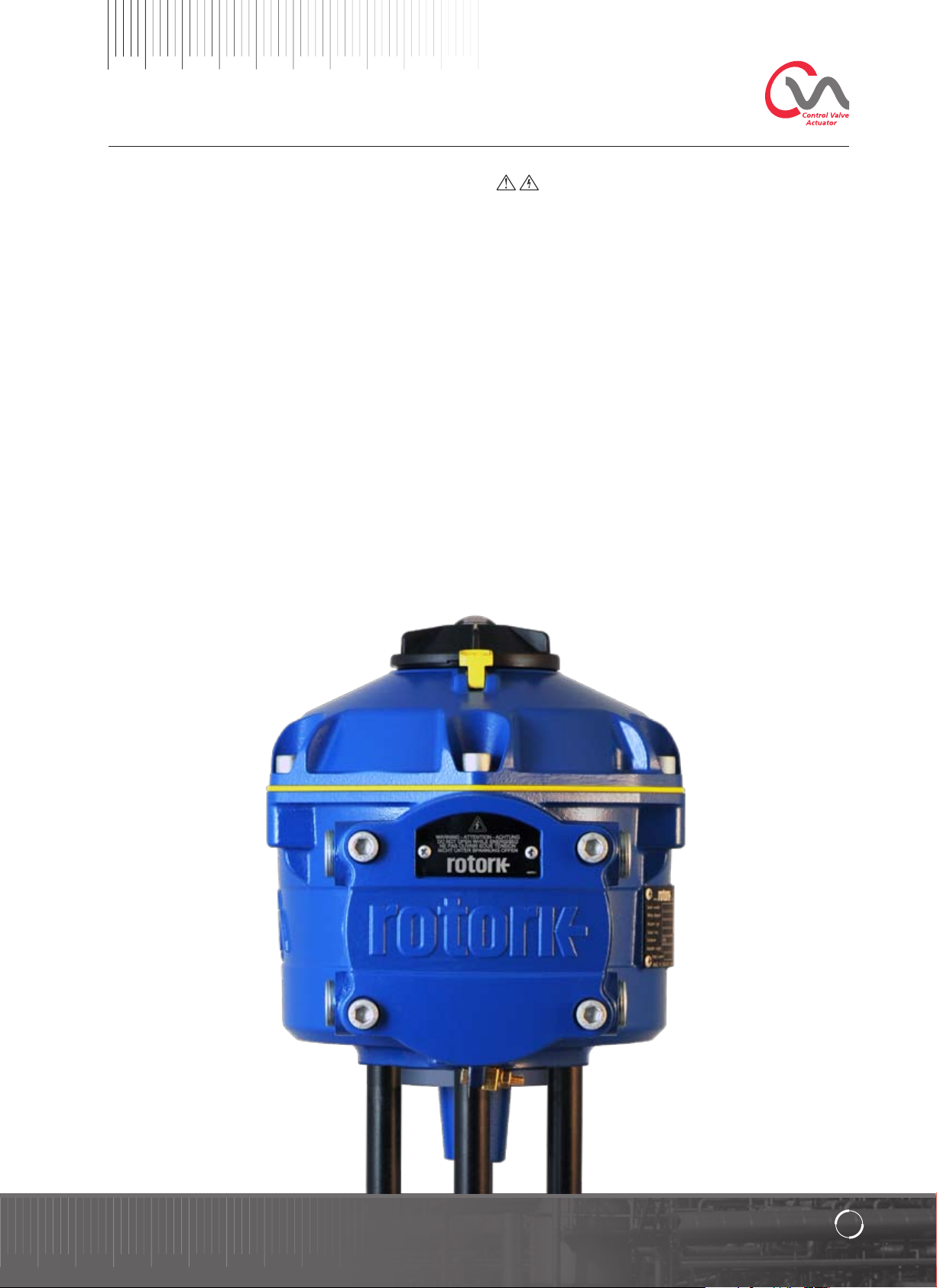
CVL Range
Linear Control Valve Actuator (CVL)
Installation & Maintenance Instructions
Publication P170E Issue 04/09
Page 2

2
Page 3

Contents
Contents
General Information 4
Hazardous Area Approvals 5
Health & Safety 6
Storage 7
Operating your CVA Actuator 8
Installation & Setup Guide 12
Mounting the Actuator 14
Cable Connections 15
Commissioning 17
Diagnostics 45
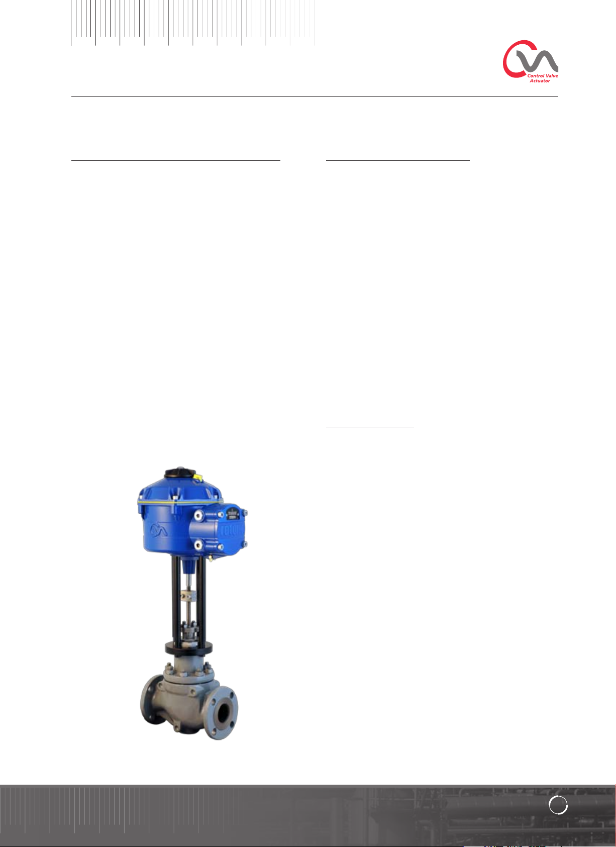
Building on Rotork’s historical success with
innovative technology, the CVL offers a highly
accurate and responsive method of automating
control valves without the complexity and cost
of a pneumatic supply. With an increased focus
on production costs and efficiency, accurate
control of the process variable is paramount.
With resolution figures better than 0.1% and the ability to
eliminate position overshoot, the Rotork CVA range helps to
maximize product quality and plant capacity.
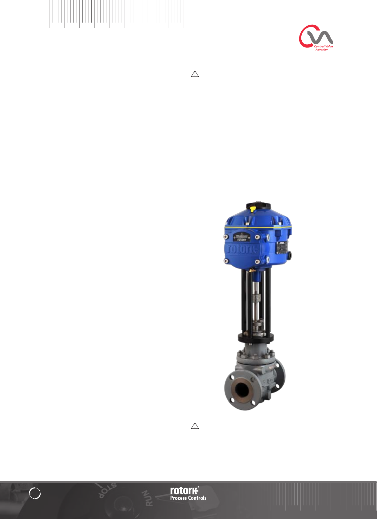
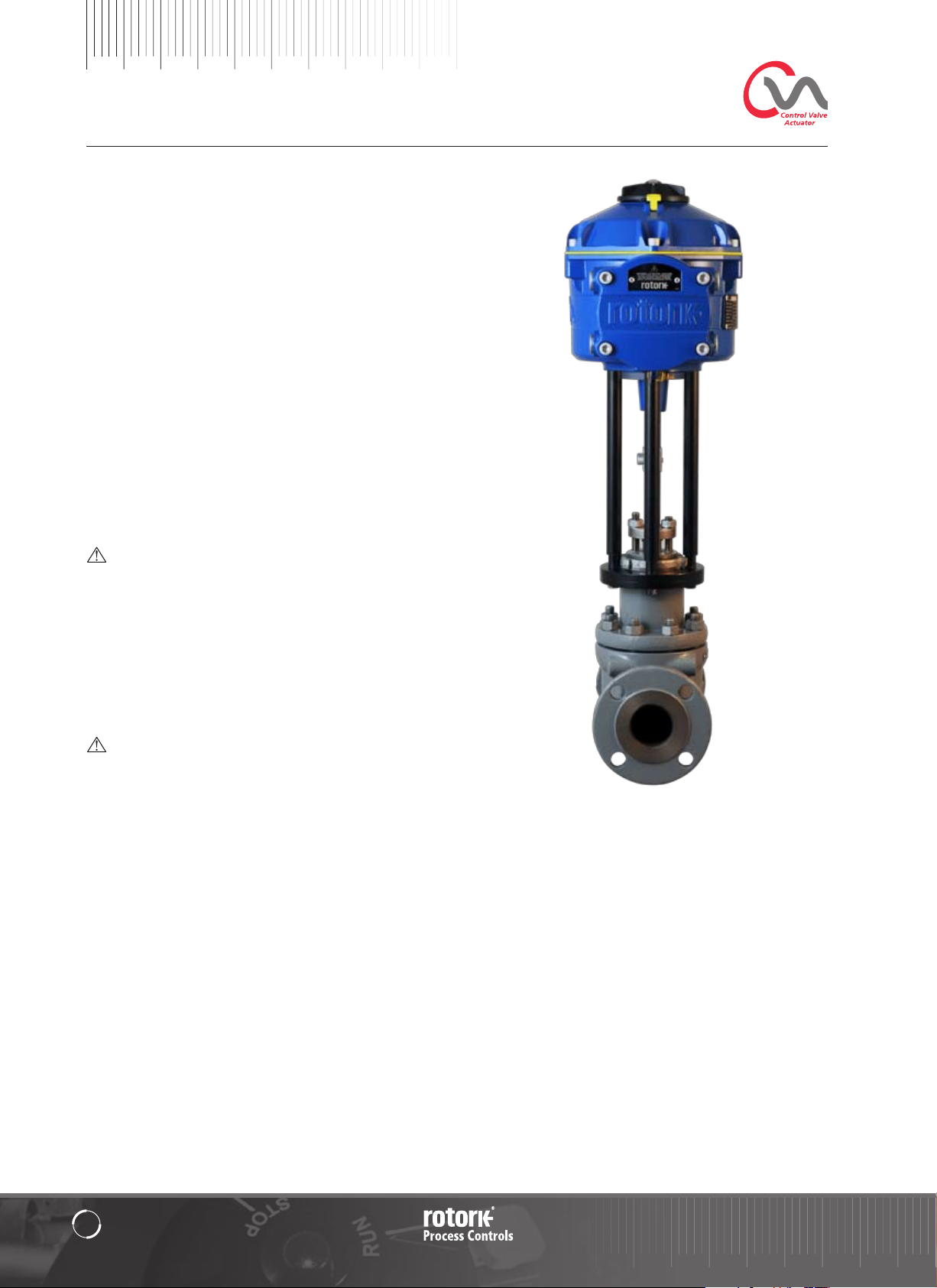
CVL range actuators are self contained, purpose designed
and built for continuous remote electrical operation of
control valves.
This Manual covers the Linear Control valve
Actuator Range (CVL).
Models: CVL 500 & CVL 1500
Refer to Rotork Publication P110E for full specification.
The actuator comprises:
• DC brushless electric motor.
• Reduction gearing with linear output shaft.
• Motor controller with speed, travel and thrust limitation.
• Electronic logic controls and monitoring facilities housed
in a double sealed watertight enclosure.
• Hazardous area certification meeting international and
national requirements.
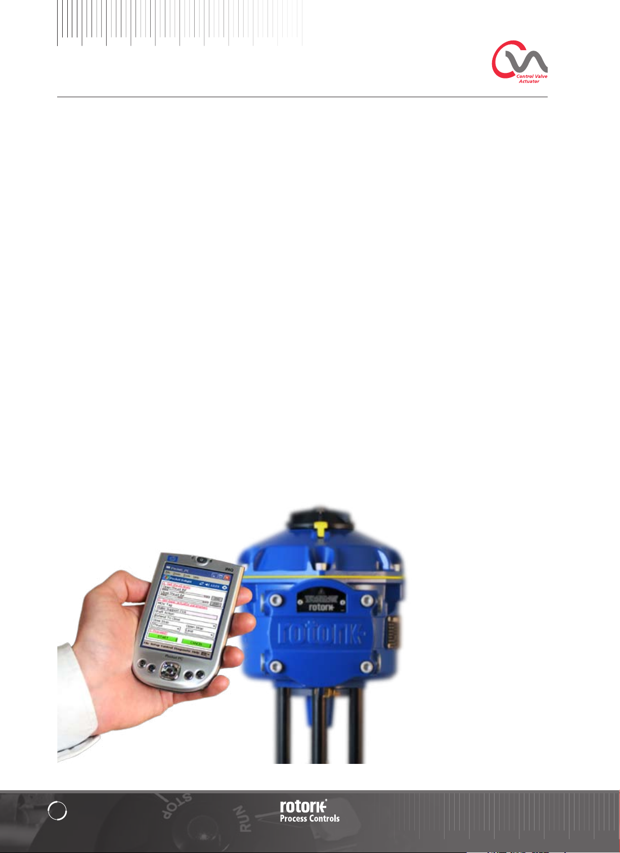
All thrust and position settings as well as configuration of the
actuator are made using a non-intrusive Bluetooth
typically a PDA (not supplied).
Bluetooth
download from www.rotork.com.
™
PDA Enlight software is available for free
™
device,
Established Leaders
in Valve Actuation Technology
3
Page 4
General Information
This manual has been produced to enable
a competent user to install, operate, adjust
and inspect the Rotork Range of Control
Valve Actuators.
The electrical installation, maintenance and use of these
actuators should be carried out in accordance with the
National Legislation and Statutory Provisions relating to
the safe use of this equipment applicable to the site of
installation.
For the UK: Electricity at Work Regulations 1989 and the
guidance given in the applicable edition of the ‘IEE Wiring
Regulations’ should be applied. Also the user should be fully
aware of their duties under the Health and Safety at Work
Act 1974.
For the USA: NFPA70, National Electrical Code
The mechanical installation should be carried out as outlined in
this manual and also in accordance with any relevant national
standard codes of practice. If the actuator nameplate indicates
that it is suitable for use in a Potentially Explosive Atmospheres
(Hazardous Areas) then the actuator is suitable for use in
Zone 1 and Zone 2 (or Div 1 and Div 2) hazardous area
classifications, as defined by the actuator’s nameplate marking.
Any equipment connected to the actuator should be of
an equivalent (or better) hazardous area certification. The
installation, maintenance and use of the actuator installed in
a hazardous area must be carried out by a competent person
and in accordance with all relevant codes of practice for the
particular Hazardous Area certification.
®
is applicable.
Any inspection or repair of Hazardous Area approved
actuators should not be undertaken unless it conforms to
National Legislation and Statutory Provisions relating to the
specific Hazardous Area. Only Rotork approved actuator
replacement parts should be used. Under no circumstances
should any modification or alteration be carried out on the
actuator, as this could invalidate the conditions under which
its certification was granted.
Access to live electrical conductors is forbidden in a Hazardous
Area unless it is done under a special permit to work,
otherwise all power should be isolated and the actuator
moved to a non-hazardous area for repair or attention.
Enclosure Materials
The enclosures on the Rotork Range of Control Valve
Actuators are manufactured from aluminium alloy with
stainless steel fasteners and a polycarbonate window. The
Local Control Knob and Manual Override Knob (when fitted)
are manufactured from a Polycarbonate/PBT plastic blend.
There is a potential electrostatic charging hazard associated
with these components and therefore they must only be
cleaned with a damp cloth.
The user must ensure that the operating environment and any
materials surrounding the actuator cannot lead to a reduction
in the safe use of, or the protection afforded by, the actuator.
Where appropriate the user must ensure the actuator is
suitably protected against its operating environment.
Should further information and guidance relating to the safe
use of the Rotork Control Valve Actuator Range be required,
it will be provided on request.
4
Page 5
Hazardous Area Approvals
Refer to the actuator nameplate for it’s specific approval details.
The CVA is built in accordance with: -
European—Hazardous Area ATEX (94/9/EC) II 2 GD c
Ex d IIB T4 Gb, Ex t IIIC T120°C Db
EN60079-0, EN60079-1, EN13463-1,
EN13463-5 and EN61241-1
Ambient Temperature Range:
-20 °C to +60 °C (-4 °F to +140 °F)
*Option -40 °C to +60 °C (-40 °F to +140 °F)
Ex d IIC T4 Gb, Ex t IIIC T120°C Db
EN60079-0, EN60079-1, EN13463-1,
EN13463-5 and EN61241-1
Ambient Temperature Range:
-20 °C to +60 °C (-4 °F to +140 °F)
*Option -40 °C to +60 °C (-40 °F to +140 °F)
Ex de IIB T4 Gb, Ex t IIIC T120°C Db
EN60079-0, EN60079-1, EN60079-7,
EN13463-1, EN13463-5 and EN61241-1
Ambient Temperature Range:
-20 °C to +60 °C (-4 °F to +140 °F)
*Option -40 °C to +60 °C (-40 °F to +140 °F)
Ex de IIC T4 Gb, Ex t IIIC T120°C Db
EN60079-0, EN60079-1 and EN60079-7,
EN13643-1, EN13463-5 and EN61241-1
Ambient Temperature Range:
-20 °C to +60 °C (-4 °F to +140 °F)
*Option -40 °C to +60 °C (-40 °F to +140 °F)
International-Hazardous Area IECEx
Ex d IIB T4 Gb, Ex t IIIC T120°C Db
IEC60079-0, IEC60079-1 and IEC61241-1
Ambient Temperature Range:
-20 °C to +60 °C (-4 °F to +140 °F)
*Option -40 °C to +60 °C (-40 °F to +140 °F)
Ex d IIC T4 Gb, Ex t IIIC T120°C Db
IEC60079-0, IEC60079-1 and IEC61241-1
Ambient Temperature Range:
-20 °C to +60 °C (-4 °F to +140 °F)
*Option -40 °C to +60 °C (-40 °F to +140 °F)
Ex de IIB T4 Gb, Ex t IIIC T120°C Db
IEC60079-0, IEC60079-1, IEC60079-7 and IEC61241-1
Ambient Temperature Range:
-20 °C to +60 °C (-4 °F to +140 °F)
*Option -40 °C to +60 °C (-40 °F to +140 °F)
Ex de IIC T4 Gb, Ex t IIIC T120°C Db
IEC60079-0, IEC60079-1, IEC60079-7 and IEC61241-1
Ambient Temperature Range:
-20 °C to +60 °C (-4 °F to +140 °F)
*Option -40 °C to +60 °C (-40 °F to +140 °F)
USA– Hazardous Area
FM. Explosionproof, Class I, Div 1, Groups C & D, T4
Ambient Temperature Range:
-20 °C to +60 °C (-4 °F to +140 °F)
*Option -40 °C to +60 °C (-40 °F to +140 °F)
FM. Explosionproof, Class I, Div 1, Groups B, C & D, T4
Ambient Temperature Range:
-20 °C to +60 °C (-4 °F to +140 °F)
*Option -40 °C to +60 °C (-40 °F to +140 °F)
FM. Dust Ignitionproof, Class II, Div 1, Groups E, F & G, T4
Ambient Temperature Range:
-20 °C to +60 °C (-4 °F to +140 °F)
*Option -40 °C to +60 °C (-40 °F to +140 °F)
CVL Linear Actuator
Established Leaders
in Valve Actuation Technology
5
Page 6
Health & Safety
WARNING
Before installing the actuator, make sure that it is suitable for
the intended application. If you are unsure of the suitability
of this equipment for your installation consult Rotork prior
to installation.
WARNING: ELECTRIC SHOCK HAZARD
Installation and servicing must be performed only by
qualified personnel.
WARNING: ELECTROSTATIC DISCHARGE
This equipment houses static sensitive devices. To protect the
internal components never touch the printed circuit boards
without using electrostatic (ESD) control procedures.
WARNING: ENCLOSURE MATERIALS
CVL 500 and CVL 1500 actuator castings are manufactured
from aluminium alloy with stainless steel fasteners. The user
must ensure that the operating environment and any materials
surrounding the actuator cannot lead to a reduction in the safe
use of, or the protection afforded by the actuator.
Where appropriate the user must ensure the actuator is
suitably protected against its operating environment.
WARNING: OPERATING BY HAND
Where actuators are supplied with the optional handwheel, note that under no circumstances should any
additional lever device such as a wheel key or wrench
be applied to the hand-wheel in order to develop more
force when closing or opening the valve. This may cause
damage to the valve and/or actuator and it may also
cause the valve to become stuck in the seated or back
seated position.
WARNING: RESERVE POWER PACK
Where actuators are supplied with the reserve Power
Pack Assembly please note that the actuator output
shaft may move after removal of the power supply.
Move the Knob Selector to the ‘STOP’ position to
prevent any unwanted electrical movement. The CVA
actuator and in particular the power pack contain no
user serviceable components and the top cover assembly
must be removed by suitably qualified personnel only.
6
Page 7
Storage
Receiving / Inspection
Carefully inspect for shipping damage. Damage to the
shipping carton is usually a good indication that it has
received rough handling. Report all damage immediately to
the freight carrier and your local CVA distributor.
Unpack the product and information packet taking care to
save the shipping carton and any packing material should
return be necessary. Verify that the items on the packing list
or bill of lading agree with your own documentation.
Storage
If your actuator cannot be installed immediately store it in a
dry place until you are ready to connect incoming cables.
If the actuator has to be installed but cannot be cabled it is
recommended that any plastic transit cable entry plugs are
replaced with PTFE sealed metal plugs.
The Rotork double sealed construction will preserve internal
electrical components perfectly if left undisturbed. It is not
necessary to remove any electrical compartment covers in
order to commission the CVL actuator.
Rotork cannot accept responsibility for deterioration caused
on-site once the covers are removed. Every Rotork actuator
has been fully tested before leaving the factory to give
years of trouble free operation providing it is correctly
commissioned, installed and sealed.
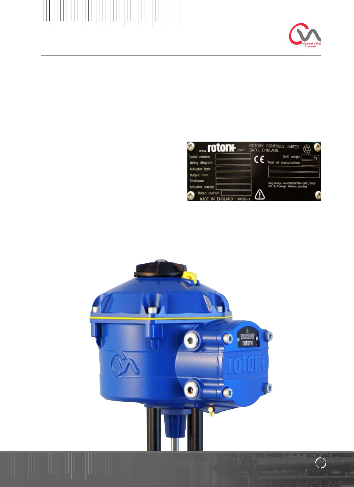
Identification Label
Established Leaders
in Valve Actuation Technology
7
Page 8
Operating your actuator
The following instructions must be followed and integrated
with your safety program when installing and using Rotork
Controls products.
• Read and save all instructions prior to installing,
operating and servicing this product.
• If you don’t understand any of the instructions contact
Rotork for clarification.
• Follow all warnings, cautions and instructions marked on
and supplied with the product.
• Inform and educate personnel in the proper installation,
operation and maintenance of the product.
Install equipment as specified in Rotork Controls
installation instructions and as per applicable local and
national codes of practice. Only connect to electrical
power supplies having the correct voltage, current and
rating (refer to nameplate).
• To ensure proper performance, use only qualified
personnel to install, operate, update and maintain
the unit.
• When replacement parts are required, ensure that the
qualified service technician uses only replacement parts
specified by Rotork.
• Substitutions will invalidate any hazardous area
certification and may result in fire, electrical shock, other
hazards or improper operation.
• Keep all product protective covers in place (except during
installation or maintenance by qualified personnel)
to prevent electrical shock, personal injury or damage
to equipment.
• Operation of the actuator in an inappropriate fashion
may cause harm or damage to the unit or surrounding
equipment.
WARNING: OPERATING BY HAND
Where actuators are supplied with the optional handwheel, note that under no circumstances should any
additional lever device such as a wheel key or wrench
be applied to the hand-wheel in order to develop more
force when closing or opening the valve. This may cause
damage to the valve and/or actuator and may also
cause the valve to become stuck in the seated or back
seated position.
Where actuators are supplied with optional hand wheel device
the valve can be operated manually independent of the power
supply.
Move the Selector Knob to the STOP position before
attempting to operate the actuator manually.
Push and turn simultaneously to manually operate the actuator.
WARNING: OPERATING ELECTRICALLY
Check that the power supply voltage agrees with that on the
actuator nameplate.
Do not switch on the power supply until you have checked
that the actuator has been connected correctly.
8
Page 9
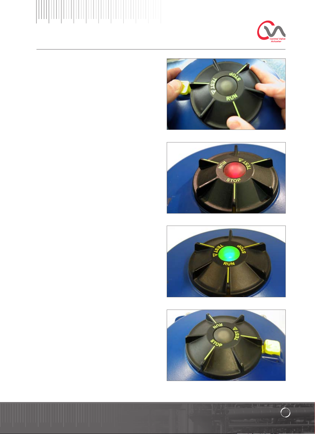
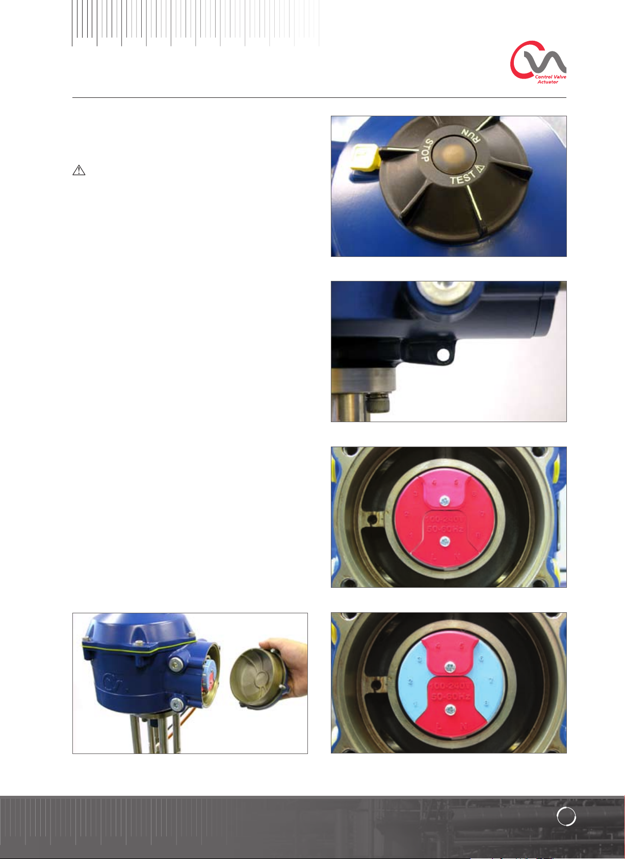
Local Controls
The actuator is supplied with a 3 position selector knob
located on the top cover assembly. The knob assembly has a
locking latch to enable the control knob to be padlocked in
position. In the centre of the knob assembly is a tri state LED.
Refer to Table 1 for full details of LED indication.
The LED has 3 colour states RED, GREEN or BLUE.
The LED can be ‘ON’ or FLASHING depending on the actuator
status.
Stop
With the selector knob in the ‘STOP’ position no electrical
operation is possible.
Run
With the selector knob in the ‘RUN’ position the actuator will
respond to remote control commands. During commissioning
or diagnostic procedures using PDA or Smartphone
Bluetooth
remotely.
Note: When STOP or RUN is selected the control knob
can be rotated between the two positions without
having to depress the locking latch. It is also possible
to lock the selector in the ‘RUN’ or ‘STOP’ only position.
™
enabled devices the actuator may not be operated
Fig. 11.1
Tes t
With the selector knob in the ‘TEST’ position an auto test
routine will be initiated if the function is enabled.
This is a quick method of testing the actuators ability to
control its output independent of the external control system.
The actuator will perform a series of step and cycle routines
centred around the last demand position. No greater than
+/- 4% of last set point.
The test will measure the following parameters:
• Deadtime
• Step Response Time.
• Setting time
• Average Thrust/Torque in each direction of travel
• Full Stroke Speed
• Valve Friction
The user LED on the selector knob will fast flash for
10 seconds.
Flashing Green - All Parameters in acceptable limits
Flashing Red - One or more parameters outside of
acceptable limits.
Fig. 11.2
Fig. 11.3
Established Leaders
Fig. 11.4
in Valve Actuation Technology
9
Page 10
Operating your actuator
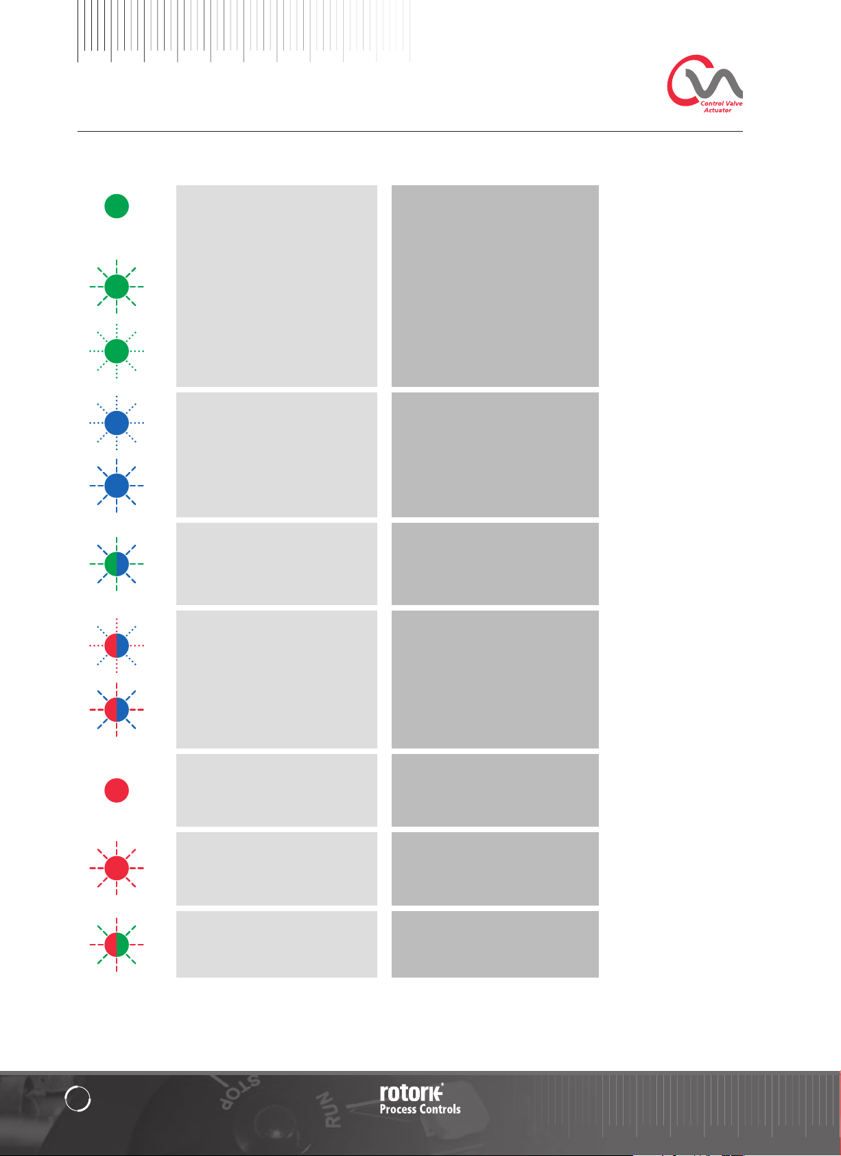
LED Indication Actuator Status Mode of Operation
Solid Green - No Faults Run or Test
Note - Electrical operation
is not possible whilst the
RPP is charging.
Green - Slow Flash
- Auto Test in progress
or Reserve Power Pack (RPP)
charging (if fitted).
Green - Fast Flash
Auto Test completed successfully.
Blue - Fast Flash
Initiating
Run
Green/Blue - Alternate Flash Run or Test
No faults.
Initiating
Stop
Fault found or Stop selected.
Solid Red Run/Test/Stop
Major Fault Found.
Flashing Red Stop
Stop selected or minor fault found.
Red/Green Alternate Flash Run/Test/Stop
Power Failure and UPS active
Bluetooth™ connection
Blue - Slow Flash
Bluetooth™ Communication Active.
Bluetooth™ communication active
Red/Blue - Alternate Fast Flash
Bluetooth™ connection
Red/Blue - Alternate Slow Flash
Bluetooth™ communication active
Note: Slow Flash = 0.5Hz
Fast Flash = 1.0Hz
10
Table 1
Page 11
RESERVE POWER PACK - (OPTIONAL)
The actuator can be fitted with an optional ‘Reserve Power
Pack’ consisting of Super Capacitors to allow the actuator to
go to a pre-determined position on power failure.
On power up the super capacitors require a charging period
during which time the actuator electrical operation will be
inhibited. This could take up to two minutes.
NOTE: Electrical operation is inhibited and the LED will
flash during the charging period.
On loss of power supply the actuator will carry out its
designated fail-to-position function. The LED remains
illuminated until the energy stored in the capacitors has
depleted.
WARNING
Where actuators are supplied with the reserve Power
Pack Assembly please note that the actuator output shaft
may move after removal of the power supply. Move
the Knob Selector to the ‘STOP’ position to prevent any
unwanted electrical movement before carrying out any
maintenance or removal of the unit from the valve.
After disconnection of the actuator power supply wait
until the LED indicator on the top cover assembly has
extinguished before attempting to remove the actuator
from the valve. Under no circumstances attempt to
remove the actuator or adjust the output drive shaft
connection to the valve stem whilst the top cover LED
is illuminated.
The CVA main housing of the actuator and in particular
the power pack contain no user serviceable components
and the top cover assembly must be removed by suitably
qualified personnel only.
DO NOT REMOVE ANY COVER ASSEMBLY TO GAIN
ACCESS TO THE ELECTRICAL COMPARTMENTS WHILST THE
LED LOCATED ON THE SELECTOR KNOB IS ILLUMINATED.
Established Leaders
in Valve Actuation Technology
11
Page 12
Installation & Setup Guide
Commissioning
The Rotork CVA Range of actuators provide simple, safe
and rapid non-intrusive commissioning using a Bluetooth
enabled PDA. Actuator limit setting can be achieved using
the automatic setup feature.
Tools & Equipment Required
BluetoothTM enabled hand held computer (PDA) or
Smartphone (screen resolution 240 x 320 minimum) running
Windows
Note: Local operation is only possible with a PDA or
Smartphone. Alternatively if the HART option card is
fitted a Hart communicator can be used.
Software
The Rotork Enlight CVA software must be installed
on the PDA or Smartphone before carrying out any
commissioning procedures. The software is free issue
and is available for download from the Rotork website
at www.rotork.com.
It is essential that the setup procedure is carried
out when the valve is not under working process
conditions, as full valve movement will occur. If
actuators are fitted with a failsafe capacitor pack
the unit may operate the valve on removal of the
power supply. To prevent this occurrence, it will be
necessary to re-configure the failsafe action, see
Page 39. Alternatively ‘STOP’ can be selected to
prevent unwanted movement.
TM
Mobile operating system.
CAUTION
IMPORTANT
It is essential that the actuator is mounted correctly to
the valve.
The height of the yoke or pillar and mounting plate, in relation
to the top of the valve spindle is critical to ensure full stroke
movement of the valve. Refer to Rotork publication P110E for
further details.
The Installation & Setup will include the following procedures:
1. Ensure valve is closed and safe (Offline).
2. Actuator output shaft is retracted.
(May be necessary to apply power).
3. Mount and align actuator to valve.
4. Use the PDA to set limits of travel.
5. Use the PDA to configure control and
indication parameters.
12
Page 13
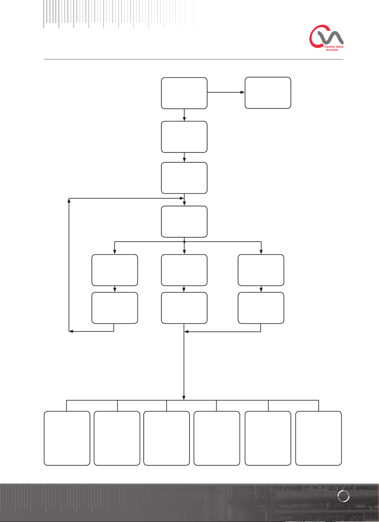
Quick Setup Flow Chart
Align Coupling
Actuator not
fitted
Establish
communication
with actuator
Select Actuator
From list
Yes
Login
Select ‘User’
Password ‘sulis’
Stroke Setup
Quick Setup
Wizard
No
Work Offline
Manual Setup
Valve Actions
Set Output Thrust
and End of Travel
Options
Align Coupling
&
Fit Actuator
Input/Output
Setup
Set Demand
& Feedback
Parameters
Auto Setup
Fail Modes
Set Loss of Power
& Signal Failure
Modes
Advanced 1
Set back off &
Indication Relay
Functions
Manually set
limits of travel
Advanced 2
Set Bumpless
Transfer Functions
Characterisation
Modify Actuator
Response against
Demand profile
Established Leaders
in Valve Actuation Technology
13
Page 14
Installation & Setup Guide
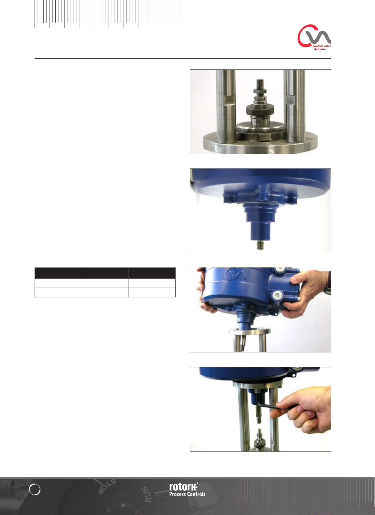
Mounting the Actuator
Move valve stem to the closed position
To enable the actuator to be installed correctly the valve must
be in the closed position to allow fitting of the valve stem/
actuator coupling.
Actuator Output Shaft
The actuator is supplied with the output shaft in the fully
retracted position. If the output shaft is in the extended
position it may be necessary to apply a temporary power
supply or manually operate the actuator using the optional
hand-wheel to the retracted position to allow installation.
Installing Actuator
Whilst no international standard currently exists for linear
flange interfaces, we conform dimensionally to MSS SP-101
and ISO 5212 for the specific flange sizes.
Actuator to mounting flange assembly fixings must conform
to Material Specification ISO Class 8.8. Delta GZ coated
Grade A4 stainless steel fixings are recommended.
Position actuator on to the valve mounting flange.
Fit securing bolts/studs and tighten down to the required
torque.
See Table 2
Fig. 16.1
Fig. 16.2
Thread Size Torque Nm Torque Lbs/ft
5/16 UNC 12.6 Nm 9.3
M8 12.8 Nm 9.4
Table 2
Fig. 16.3
14
Fig. 16.4
Page 15
Cable Connections
Move the mode selector knob on top of the required actuator
to the ‘STOP’ position. This will inhibit electrical operation.
WARNING
Ensure all power supplies are isolated before removing
actuator covers.
Check that the supply voltage agrees with that stamped on
the actuator nameplate. A fuse or circuit breaker must be
included in the wiring installation of the actuator. The switch
or circuit breaker must be installed as close as possible to
the actuator and shall be marked to indicate that it is the
disconnecting device for that particular actuator. The actuator
must be protected with an over current protection device
rated in accordance with publication No. P110E, which details
the electric motor performance data for CVA range actuators.
Earth Ground Connections
An internal earthing point is provided for water tight
applications. In addition a mandatory 6mm external earthing
stud is provided for all explosion proof applications.
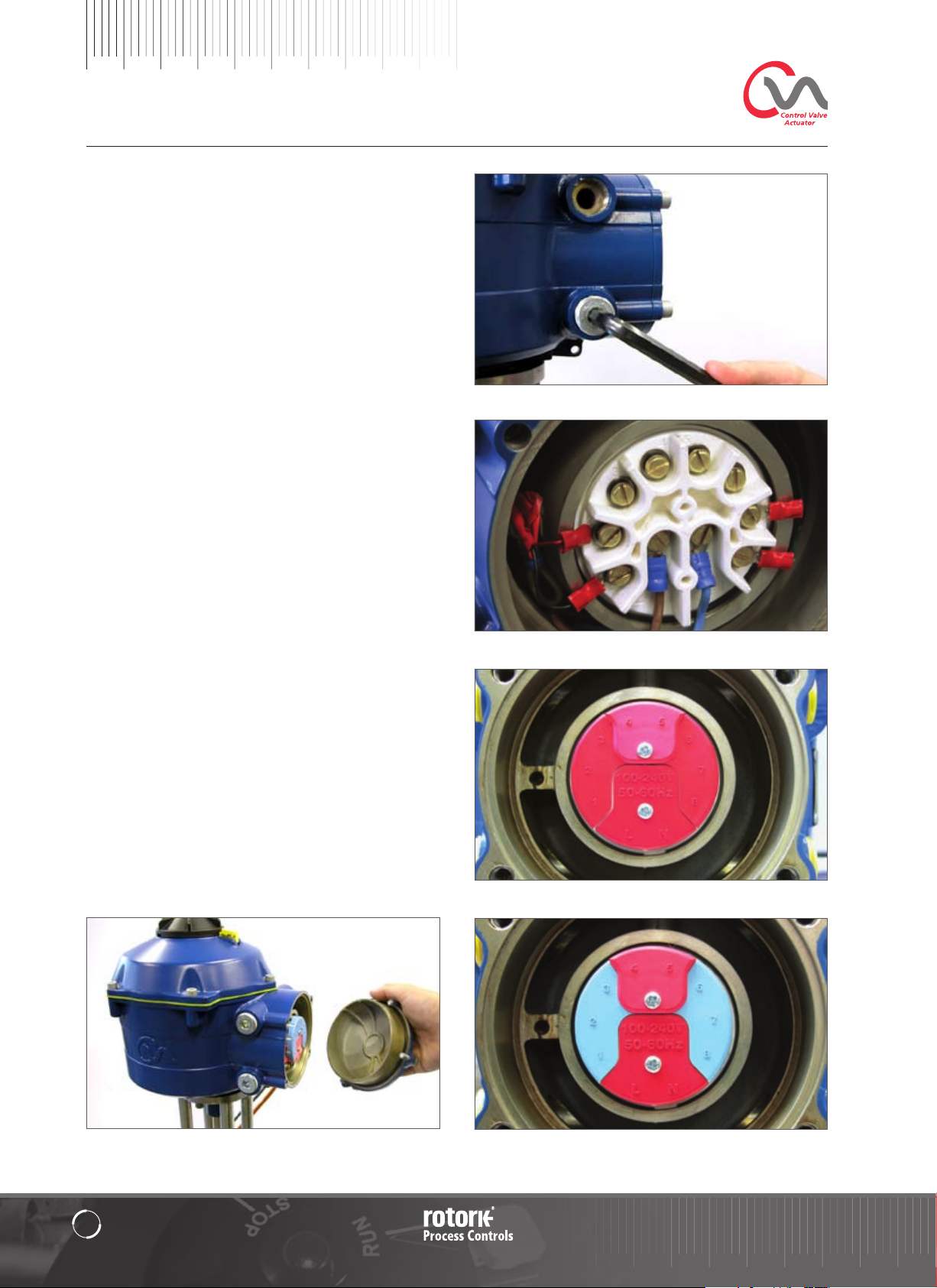
Removing Terminal cover
Using an 8mm Allen key loosen the captive fixings securing
the terminal compartment cover. Do not attempt to lever
off the cover with a screwdriver as this will damage the “O”
ring seal and may damage the flamepath on a certified unit.
Remove the power terminal insulated cover and connect
temporary or site wiring in accordance with the supplied
wiring diagram.
Note: The Red Power and Control terminal protective
covers should be replaced prior to refitting of the
electrical cover assembly.
When the actuator is supplied with an Intrinsically
Safe terminal compartment, the unit is supplied with
a Red and Blue terminal cover. The Blue terminal cover
identifies the IS Circuit connections.
Covers must be fitted to maintain certification.
Fig . 17.1
Fig. 17.2
Fig. 17.5
Established Leaders
Standard Terminal Block - Fig. 17.3
IS Terminal Block Fig. - 17.4
in Valve Actuation Technology
15
Page 16
Installation & Setup Guide
Cable entry
The cable entries are tapped either ¾” NPT or M25. Remove
any plastic transit plugs. Make off cable entries appropriate to
the cable type and size. Ensure that threaded adaptors, cable
glands or conduit are tight and fully waterproof. Seal unused
cable entries with steel or brass threaded plugs.
If the actuator is to be installed in a hazardous area, a suitably
certified cable gland must be fitted with the use of a certified
thread adaptor where appropriate.
Unused entries must be closed with a suitably certified
stopping plug.
Wiring installation must comply with local statutory
regulations.
Connecting to Terminals
On EExde enclosure units, connections to the power and
control terminals must be made using AMP type 160292 ring
tabs for power and earth terminals and AMP type 34148 ring
tabs for the control terminals.
Refer to the wiring diagram to identify functions of terminals.
Check that the supply voltage is the same as that marked on
the actuator nameplate.
Remove power and control terminal screens. Begin by
connecting the power cables followed by the control cables
(as required). Refit power and control terminal screens.
When all connections are made, refit protective terminal
covers.
Note: The Power and the Control terminal protective covers
should be fitted prior to refitting of the electrical cover
assembly.
When the actuator is supplied with an Intrinsically
Safe terminal compartment the Red and Blue terminal
covers MUST be fitted to maintain certification.
Fig. 18.1
Fig. 18.2
Replacing Terminal Cover
Ensure cover ‘O’ ring seal and spigot are in good condition
and lightly greased before refitting cover.
Fig. 18.5
16
Standard Terminal Block - Fig. 18.3
IS Terminal Block Fig. - 18.4
Page 17

Commissioning
Move the actuator selector knob to the
’STOP’ position
Apply Electrical Power
On completion of the correct assembly and electrical
connection procedures, the electrical power supply can now
be applied to the actuator.
NOTE: If the unit is fitted with failsafe capacitors the
Green or Red LED (depending on Mode selected) on the
selector will flash until the capacitors are fully charged.
Movement is not possible whilst the LED is flashing.
Fig. 19.1
Establish Bluetooth
It is now required to establish communications in order to
complete the fitting procedure.
Ensure Bluetooth is enabled on the PDA then click on the
Enlight Icon to start the program.
The maximum range of Bluetooth communication is
10 Meters.
The first screen gives the option to connect to an actuator or
open a saved file.
WORK OFF LINE
If there is a configuration file stored in the PDA it can be
opened to review files.
RECONNECT AN ACTUATOR
If a link between the PDA and actuator has previously been
established a list will appear and a search for new devices will
not occur.
TM
Communications
Fig. 19.2
DISCOVER A NEW ACTUATOR
The PDA will search a radius of 10 meters for CVA actuators.
QUIT
Exit the menu.
Established Leaders
Fig. 19.3
in Valve Actuation Technology
17
Page 18

Installation & Setup Guide
Reconnect or discover an actuator
Searching for Actuator
The PDA will now search for any CVA actuators within
Bluetooth range.
If there is more than one device a list will be generated.
Highlight, then select the required actuator from the list
of units within range.
The actuator will generally report its identity by its serial
number (shown on nameplate).
This can be modified to add an MOV or Tag reference.
(See full PDA menu details)
If there are numerous Bluetooth devices in range the search
process will take longer to complete and in some cases may
have to be repeated.
Login procedure
Before the link can be established it is necessary to log in.
There are three levels of login with password protection
to limit higher level access.
Fig. 20.1
View
Allows review of actuator settings only. No changes can
be made.
Password : view
User
Allows access to review and change actuator settings.
Includes the facility to set limits of travel and take local
control of the actuator.
Default Password : sulis
This password can be changed using the ‘file’ menu to
provide additional site security.
DO NOT LOSE THE PASSWORD INFORMATION
Rotork Engineer
Rotork use only.
Login
Select ‘User ‘ on the User Level drop down menu.
Note, user is the default and will appear in the box.
Using the keyboard at the bottom of the screen, type in
the password then click on ‘OK’ to start the procedure. If
communication is successful you will be prompted to wait
whilst the setup data is retrieved from the actuator.
Fig. 20.2
18
Fig. 20.3
Page 19

Stroke Setup Menu
There are three choices from this menu.
Align Coupling
If the actuator is not fully fitted to the valve this procedure
must be carried out to enable correct assembly and alignment
of the actuator coupling to the valve stem.
Quick Setup Wizard
Use this menu to automatically set actuator limits of travel.
Go to Page 24
Manual Setup
Use this menu to manually set actuator limits of travel.
Go to Page 29
It is possible on this screen to choose Imperial or Metric units.
The actuator serial number, current valve stroke and position
are also displayed.
WARNING
The default setting of a new actuator is minimum thrust
and extend to close. If the actuator has previously been
commissioned it is essential that its basic settings are checked
before fitting the coupling and operating the actuator
electrically. Check the settings in the Manual Setup menu
and adjust if necessary.
Fig. 21.1
WARNING
When RUN mode is selected the actuator will respond to any
active remote control commands.
Select ‘STOP’ on the Actuator Selector Knob to prevent
any unwanted movement.
Fitting Actuator to Valve
Select the ‘ALIGN COUPLING’ option.
Select Metric or Imperial Units as required.
Fig. 21.2
Fig. 21.3
Established Leaders
in Valve Actuation Technology
19
Page 20

Installation & Setup Guide
Fig. 22.1
1. Set thrust limits
The maximum amount of thrust available for the open and
close direction of travel can be adjusted by dragging the
slider from left to right.
2. Set basic actuator parameters
MOV Tag
The actuator can be given a TAG number for ease of
identification in the field.
Shaft Action
Set open or closed direction to extend the output drive shaft.
Close/Open Stop
Thrust - Apply set thrust to the valve stem at end of travel
limit where valve tight shutoff is required.
Limit - Stop the actuator at the set limit where valve does not
require tight shutoff.
Select the START option to save changes and proceed
to align the coupling.
Select basic parameters and thrust limit settings as required.
Fig. 22.2
3. Proceed To Align Coupling
To commence manual alignment of shaft, click on the start
box to align the actuator to the valve.
WARNING
When RUN mode is selected the actuator will respond
to any active remote control commands.
If no Analogue request is applied, the actuator will carry out
its loss of control signal fail to position function. If necessary
go to the Fail Modes Menu and select the Disabled option
and send the settings back to the actuator.
20
Fig. 22.3
Fig. 22.4
Page 21

Align Coupling
It is now possible to operate the actuator using the Enlight
program. Moving the position control slider will extend or
retract the output shaft to enable it to be connected to
the valve spindle. Coarse control will allow full travel of the
actuator. Fine control is used for small adjustments of the
actuator spindle.
Incrementing the position slider using the arrows
will vary position by 1% for coarse and 0.1% for fine
control.
When the position control is operated for the first time a
warning will appear to indicate that the actuator will be taken
offline and will not respond to remote control commands.
CAUTION
The actuator will move to the indicated position on the
Position Control Slider.
Select OK
Click on the ‘OK’ button and the actuator will be taken offline
and will now move to the position as indicated on the position
control slider.
The actuator is now unavailable for remote control.
Connect the output shaft to valve spindle.
Using the position control slider move the output shaft to
the full actuator output shaft travel limit or until it reaches
the valve spindle leaving minimal gap and ensure there is no
misalignment between the two shafts. If the actuator output
shaft reaches its fully extended position it will be necessary
to retract the shaft a sufficient distance to ensure a tight shut
off in thrust seating valves.
Fig. 23.1
WARNING
It is critical that there is correct alignment between
actuator output shaft and the valve stem.
Note: Mis-alignment will result in increased mechanical
wear and possible damage to the valve stem.
If the output shaft and valve stem are not aligned correctly
then adjust the mounting position of the yoke and actuator
as necessary.
Fig. 23.4
Fig. 23.2
Fig. 23.3
Established Leaders
in Valve Actuation Technology
21
Page 22

Title Here
Installation & Setup Guide
Connect the output shaft to the valve spindle using a
suitable coupling.
It is now possible to set the end of travel limits.
Quick Setup Wizard
If the valve is to be commissioned over its full stroke the quick
setup wizard is a fast and efficient way to set the end of
travel limits. The quick set up wizard will allow the actuator to
find the end of travel by measuring the output thrust. If the
valve is not capable of accepting thrust in the open direction
it is possible to set a fixed limit.
Select Quick Setup Wizard
Set thrust limits
The default thrust values for the Auto setup are automatically
set to 40% of rated thrust in both directions. Adjust if more
thrust is required to move the valve through stroke.
Set basic actuator parameters
The MOV tag can be edited. Use the keyboard to edit the
MOV tag field.
Shaft Action
Select Extend or Retract output shaft to suit valve operation.
Close/Open Stop
Set the end of travel stop function for Thrust or Limit to suit
the characteristics of the valve.
Thrust
The actuator can be set to apply its selected output ‘Thrust’ to
the valve at the end of travel where tight shut off is required.
Limit
Alternatively it can be set to the ‘Limit’ function to disengage
motor drive and stop the valve at a predetermined position
where the valve does not require the seating force to be
applied to the valve seat or end of mechanical valve travel.
Click on the ‘START’ box to save changes to the actuator and
initiate the Auto Setup routine.
Fig. 24.1
Fig. 24.2
22
Page 23

0 pt
Move the selector Knob to the ‘RUN’ position
CAUTION
Initiating an Auto Setup will move the valve through
its full stroke.
WARNING
Steps 1 and 2 must be checked to ensure the thrust,
shaft action and end stops are correctly set or damage
to the valve may occur.
AUTO LIMIT will initiate the auto setting procedure.
FIXED LIMIT will allow the actuator to find the closed limit
by measuring the thrust but will allow the open limit to be
set at a measured distance. The distance can be edited in the
text box.
NOTE: Ensure that limit is selected for the open stop if fixed
limit is applied.
Established Leaders
in Valve Actuation Technology
Fig. 25.1
Fig. 25.2
23
Page 24

Installation & Setup Guide
The Auto Setup is fully automatic and requires no user input
Start Auto Setup?
Click on the ‘START’ box to initiate the Auto setup procedure.
Click on the OK box to continue. All other menus will be
disabled until the process is completed.
Fig. 26.1
Finding the Extended (Closed) Limit
The actuator will move its output shaft to the maximum
CLOSED limit of travel.
Fig. 26.3Fig. 26.2
Actuator will then move its output shaft away from the
Closed limit of travel and repeat the procdeure to eliminate
any inertia effects and re-adjust the end of travel limit as
necess ary.
Fig. 26.5Fig. 26.4 Fig. 26.6
Finding the Open Limit
The actuator will move its output shaft to the maximum
CLOSED limit of travel. Actuator will then move its output
shaft away from the Closed limit of travel and repeat the
procdeure to eliminate any inertia effects and re-adjust the
end of travel limit as necessary.
24
The Open position limit is now set and Auto Setup
is Complete.
Page 25

0 pt
ACTUATOR AUTOMATIC SETUP IS NOW COMPLETE
Auto setup is now complete and both ends of travel tight
shut off limits have been defined and set.
PDA screen will return to the Stroke Set up menu.
If no further settings are required move the Mode selector
to the ‘STOP’ or ’RUN’ positions depending on desired
Operation. Exit the menu.
For further settings continue on Page 34.
Fig. 27.1
Established Leaders
in Valve Actuation Technology
25
Page 26

Title Here
Installation & Setup Guide
Manual Setup Flow Chart
Align Coupling
Actuator not
fitted
Establish
communication
with actuator
Select Actuator
From list
Yes
Login
Select ‘User’
Stroke Setup
Quick Setup
Wizard
No
Work Offline
Manual Setup
Valve Actions
Set Output Thrust
and End of Travel
Options
Align Coupling
&
Fit Actuator
Input/Output
Setup
Set Demand
& Feedback
Parameters
Auto Setup
Fail Modes
Set Loss of Power
& Signal Failure
Modes
Advanced 1
Set back off &
Indication Relay
Functions
Manually set
limits of travel
Advanced 2
Set Bumpless
Transfer Functions
Characterisation
Modify Actuator
Response against
Demand profile
26
Page 27

0 pt
Manual Setup
CAUTION
To prevent unwanted electrical operation move the
selector knob to the ’ STOP’ position.
If manual setting is required or if the limits are to be set for a
reduced stroke operation the Manual Setup can be utilised.
From the Stroke Setup page select the Manual Setup option.
WARNING
Before carrying out this procedure verify that the thrust
limits and basic actuator parameters are set correctly to
prevent damage to the valve.
Set Thrust Limits
The default thrust values for the Manual setup are
automatically set to a low value for the commissioning
procedure.
Open value 40% thrust (200lbf on a CVL 500).
Close value 40% thrust.
Increase the thrust if necessary.
Set Basic Actuator Parameters
The MOV tag can be edited by using the keyboard at the
bottom of the screen.
Shaft Action
Select Extend or Retract output shaft to suit valve operation.
Close / Open Stop
Set the end of travel stop function for Thrust or Limit to suit
the characteristics of the valve.
Thrust
The actuator can be set to apply its selected output ‘Thrust’
to the valve at the end of travel where tight shut off is
required.
Limit
Alternatively it can be set to the ‘Limit’ function to disengage
motor drive and stop the valve at a predetermined position
where the valve does not require the seating force to be
applied to the valve seat or end of mechanical valve travel.
Proceed to Manual Setup
Click on the ‘START’ box to confirm changes and commence
the Manual Setup procedure.
Fig. 29.1
Established Leaders
Fig. 29.2
in Valve Actuation Technology
27
Page 28

Title Here
Installation & Setup Guide
To Enable electrical operation move the Selector Knob
to the RUN position.
CAUTION
Note the actuator may respond to any present remote
control requests during loss of Bluetooth commands or
when navigating between screens.
It is now possible to move the output shaft to the desired
Position using the position control slider
CAUTION
The actuator will be taken offline and will respond to
the position control slider.
Confirm that settings are correct before attempting to
move the actuator.
Click on OK to proceed.
.
Fig. 30.1 Fig. 30.2
When the output shaft is in the desired position, the travel
limit can be set using the SET OPEN / SET CLOSE box.
Set Close Limit
Use the Position Control Slider to move the actuator output
shaft to the required Closed position. Fig 30.2.
Click on the ‘Set Close’ box to calibrate the closed limit of
travel. The ‘Set Close’ and the ‘Serial’ number boxes are
‘greyed’ out during the calibration procedure and indicate
acceptance of the new settings when cleared. Fig 30.3.
The new close limit position is now shown on the main
scale Indicator. Fig 30.4.
28
Fig. 30.3
Fig. 30.4
Page 29

0 pt
Set Open Limit
Use the Position Control Slider to move the actuator output
shaft to the required Open position.
Click on the ‘SET OPEN’ box to calibrate the closed limit of
travel. The ‘Set OPEN’ and the ‘Serial’ number boxes are
‘greyed’ out during the calibration procedure and indicate
acceptance of the new settings when cleared.
The new open limit position is now shown on the main
scale indicator.
The new limits of travel are shown on the green and red
scales and as inches/mm position and percentages relative to
the actuators full mechanical stroke.
Fig. 31.1
Manual Setup is now Complete.
Established Leaders
Fig. 31.2
Fig. 31.3
in Valve Actuation Technology
29
Page 30

Title Here
Installation & Setup Guide
Configurations Options
Setup Flow Chart
Establish
communication
with actuator
Select Actuator
From list
Yes
Login
Select ‘User’
Stroke Setup
No
Work Offline
File
Save & Load
Configuration
from Actuators
& Files
Valve Actions
Set Output Thrust
and End of Travel
Options
Input/Output
Setup
Set Demand
& Feedback
Parameters
Setup
Fail Modes
Set Loss of Power
& Signal Failure
Modes
Control
Manual Control
& Test
Advanced 1
Set back off &
Indication Relay
Functions
Diagnostic
Advanced 2
Set Bumpless
Transfer Functions
Characterisation
Modify Actuator
Response against
Demand profile
30
Page 31

0 pt
File
From the lower tool bar the menus allow configuration
settings to be stored and updated.
Load Config from CVA
This option will download the actuator configuration of the
currently connected actuator to the PDA to allow verification
of the settings.
The ‘Transferring data’ screen will be active during the
download.
Save Config to CVA
Upload the current configuration stored from the PDA to
the actuator.
The ‘Transferring data’ screen will be active during the
download.
Load Config from File
VIEW
Use this screen to load a configuration file for review.
On the PDA. This will disconnect the current actuator.
Fig. 33.1
UPDAT E
Use this screen to update the current actuator with a
previously saved file.
Configurations Options
Use this option to Save actuator configuration to the PDA or
actuator memory.
Load configuration data from previously saved files from PDA
to the actuator.
Fig. 33.2
Established Leaders
Fig. 33.3
in Valve Actuation Technology
31
Page 32

Title Here
Installation & Setup Guide
Save Config to file
Save the current actuator configuration to a file location on
the PDA.
‘Save config to file’ will open a new screen to save file in
PDA. File will be identified by actuator serial number.
This can be edited. The file location can also be selected
from this screen.
Save will initiate the process
32
Fig. 34.1
Fig. 34.3
Fig. 34.2
Fig. 34.4
Page 33

0 pt
Macro Update
ROTORK USE ONLY
No USER function.
Configuration Settings
Further menu options are available from the lower tool bar
as follows:
Setup
Stroke Setup
Align Coupling
Quick Setup Wizard
Manual Setup.
Valve Actions
Configure thrust output options, direction to close and
MOV tag.
Input/Output Setup
Configure Analogue demand and Feedback options.
Fail Modes
Configure Power and loss of signal failure actions.
Advanced 1
Configure backoff and status relay options.
Advanced 2
Configure bumpless transfer options.
Characterisation
Configure actuator response to demand characteristic.
Change Password
Change Actuator Password.
DO NOT lose the Password information if changed
from the Default.
Fig. 35.1
Fig. 35.2
Control
Manual control
Operate the actuator manually by Bluetooth
Run test
Run a selection of step and wave tests.
Established Leaders
TM
command.
Fig. 35.3
in Valve Actuation Technology
33
Page 34

Title Here
Installation & Setup Guide
Valve Actions
From the lower tool bar menu select Valve Actions.
Fig. 36.2Fig. 36.1
The following settings are available:
Open/Close Thrust
Maximum allowed output thrust can be varied between 40%
to 100% of rated in both Open and Close directions.
The thrust is displayed in lbf or N.
MOV Tag
Modify as required.
Shaft Action
Extend or Retract to close (Extend is Default).
Close / Open Stop
Set the end of travel stop function for Thrust or Limit to suit
the characteristics of the valve.
Thrust
The actuator can be set to apply its selected output
‘Thrust’ to the valve at the end of travel where tight shut
off is required.
Limit
Alternatively it can be set to the ‘Limit’ function to disengage
motor drive, where the valve does not require the seating
force to be applied.
Send Settings
Send modified settings to the actuator.
34
Page 35

0 pt
Input / Output Setup
From the lower tool bar select Input/Output Setup.
Fig. 37.2Fig. 37.1
Close Demand mA Calibration
Set mA Demand level at fully Closed position.
Apply minimum (0%) Setpoint Signal to the actuator demand
input terminals and use the appropriate ‘SET’ box to calibrate.
The setpoint will be calibrated to the Measured Demand mA
value displayed in the box.
Open Demand mA Calibration
Set mA Demand level at fully Open position.
Apply maximum (100%) Setpoint Signal to the actuator
demand input terminals and use the appropriate ‘SET’ box
to calibrate.
The setpoint will be calibrated to the Measured Demand mA
value displayed in the box.
Close Feedback mA Calibration
Set required mA Feedback level at the fully Closed position by
typing in the value directly to the 0% Feedback box. Select
SEND settings to save changes.
Open Feedback mA Calibration
Set required mA Feedback level at the fully Open position by
typing in directly to the 100% Feedback box. Select SEND
settings to save changes.
Damping
If the actuator responds unnecessarily to a rapidly fluctuating
setpoint signal the Damping feature can be used to ‘damp’
out the response by applying a delay in the response to a
change in signal.
Adjust the damping time delay (milliseconds) setting to
achieve stable system operation.
4-20mA Output
Can be configured to show the actuator position or
output thrust.
Send Settings
Send modified settings to the actuator.
Demand Deadband
If the actuator hunts or responds unnecessarily to a
fluctuating setpoint signal, the Deadband may be increased.
The Deadband can be varied between 0% and 10%.
Established Leaders
in Valve Actuation Technology
35
Page 36

Title Here
Installation & Setup Guide
Fail Modes
From the lower tool bar select Fail Modes.
Fig. 38.2Fig. 38.1
Power Failure Mode
(Units fitted with Reserve Power Pack option only).
On power failure the actuator can be set to carry out the
following actions:
Move to Closed limit of travel
Move to Open limit of travel
Stayput
Go To Position
Power Failure Delay
Delay before failsafe action is adjustable up to a maximum
of 10 seconds.
NOTE: The LED on the mode selector will remain
illuminated until the Reserve Power Pack failsafe
capacitors are fully discharged.
Loss of Signal Position
On loss of the 4 - 20mA analogue control signal the ‘Fail to
Position’ can be set to carry out one of the following actions:
Move to Closed limit of travel
Move to Open limit of travel
Move to a pre- determined position
Delay Fail to Position response up to 10 seconds.
36
Page 37

0 pt
Advanced 1
Fig. 39.1
Tight Shut Off Threshold Close
This box indicates the highest level analogue mA setpoint as
a percentage that will fully close (tight shut off) the valve.
The example shown in Fig 39.2 states that a 0.5% or lower
control request will give a tight shut off (closed) on the valve
Tight Shut Off Threshold Open
This box indicates the lowest level analogue mA setpoint as
a percentage that will fully open the valve.
The example shown in Fig 39.2 states that a 99.5% or greater
control request will give a tight shut off (open) on the valve.
Obstruction Back off
If enabled the actuator will back off the movement if the
maximum thrust is exceeded during travel. The actuator will
make 3 attempts to back off and return to the setpoint.
If disabled the actuator will remain stationary until a
request to move in the opposite direction is received or the
obstruction is removed.
Back off Distance
The distance the actuator backs off can be selected on the
drop down menu as shown.
Fig. 39.2
Test Knob
The Mode Selector Knob can be disabled to prevent the
actuator carrying out a pre-determined test routine when
the ‘TEST’ position is selected on the control knob.
Back off Time
Can be set to a maximum of 5 seconds before back off is
executed.
Established Leaders
in Valve Actuation Technology
37
Page 38

Title Here
Installation & Setup Guide
Status Relay
The actuator has a programmable fault relay that can be set
to indicate one of the following conditions shown in Table 3.
Mode Description
Disabled Always de-energised to reduce
power consumption
Availability Active when the CVA is capable of being
remotely controlled
Actuator is in Remote Mode
Actuator has no faults which would
prevent operation
Fault Active with any detectable fault within
the actuator, control or valve
Open Limit Active when the actuator is at the
Fully Open position
Closed Limit Active when the actuator is at the
Fully Closed position
Open Thrust Active when the actuator has reached
the Opening Thrust Limit
Close Thrust Active when the actuator has reached
the Closing Thrust Limit
Thrust Limit Active when the actuator has reached
the Opening or Closing Thrust Limit
Failsafe Active when the actuator is performing
its Failsafe action
Fig. 40.1
Table 3
The relay contact type can be configured for Normally Open
(NO) or Normally Closed (NC) by using a different wiring
configuration. This can be selected during the ordering stage
and will be reflected in the Wiring Diagram number.
See Table 3 for details of relay functions.
38
Page 39

0 pt
Advanced 2
Fig. 41.2Fig. 41.1
Direction Change Threshold Distance
The distance the actuator must move before a direction
change is registered by the datalogger as a cycle.
This is used to prevent small dither movements from
being counted as these are considered too small to cause
valve wear.
The default setting is 0.25% of overall valve travel.
Total Direction Changes Before Alarm
Can be used to generate an alarm when a set number of
direction changes has occurred.
Total Travel Before Alarm
Can be used to generate an alarm when a set distance has
been travelled by the actuator output drive shaft ft/meters.
Bumpless Transfer
On start up of the process or after manual intervention the
actuator could be required to move a long way to its setpoint.
If the actuator moved at too great a speed this could cause
a ‘bump’ or instability in the control system loop leading to
valve overshoot and oscillation.
To reduce this effect the ‘bumpless transfer’ reduces the
actuator output speed to a lower level if the distance to travel
is more than a pre-determined value. Once the actuator
arrives within the Bumpless Transfer Distance (BTD) area it will
resume travel at its normal speed.
Bumpless Transfer Distance (BTD)
The bumpless transfer distance is a pre defined percentage
of position error that will reduce the actuator speed to a
pre-determined speed.
The Default Bumpless Transfer Distance is 5%.
Bumpless Transfer Speed
The speed in % of rated maximum speed that the actuator
will revert to if the bumpless transfer distance is exceeded.
The actuator will resume normal set speed once it arrives
within the preset BTD.
The Default Bumpless Transfer Speed is 40% of rated.
Send Settings
Upload the Advanced 2 configuration changes to
the actuator.
Established Leaders
in Valve Actuation Technology
39
Page 40

Title Here
Installation & Setup Guide
Characterization
The actuator relationship between the Demand Request and
the Demand Signal is Linear by default.
Use the Valve Characteristic drop down menu to select
between the following:
Linear
The actuator position responds directly to the mA
demand request.
Fig. 42.1
Quick Opening
The actuator responds quickly to the demand signal at
the lower end of travel. Reduced response near the
open position.
40
Fig. 42.2
Fig. 42.3
Page 41

0 pt
Equal Percentage
The change in actuator position is directly proportional to the
demand request.
Valve Position & Demand Signal
The position against demand profile can be tailored to suit
the valve application by plotting the characteristic at up to 20
co-ordinate points on the graph.
Click on the Valve Position box and highlight the required
valve position (5% increments).
Fig. 43.1
Type in the corresponding Desired Signal % and click on the
Update box.
Use the update box to store the co-ordinate point.
Established Leaders
Fig. 43.2
Fig. 43.3
in Valve Actuation Technology
41
Page 42

Title Here
Installation & Setup Guide
Mode
The characteristic Profile can be applied to both the Input and
Output signals or individually if required.
Click on the SEND SETTINGS box to save the changes to the
actuator configuration.
Change Password
This menu allows the actuator password to be changed.
Note: If the actuator Password is changed it will not
be possible to communicate with the unit, unless the
correct password is used.
Fig. 44.1
DO NOT LOSE THE PASSWORD INFORMATION.
CONTACT ROTORK IN CASE OF LOST PASSWORD
INFORMATION.
Fig. 44.2
Note
Engineer 1
Engineer 2
These screens are for Rotork use only.
42
Fig. 44.3
Page 43

0 pt
Control & Diagnostics Options
Setup Flow Chart
Login
Select ‘User’
File
Save & Load
Configuration
from Actuators
& Files
Setup
Establish
communication
with actuator
Yes
Select Actuator
From list
Stroke Setup
No
Control
Manual Control
& Test
Work Offline
Diagnostic
Valve Actions
Set Output Thrust
and End of Travel
Options
Input/Output
Setup
Set Demand
& Feedback
Parameters
Established Leaders
Fail Modes
Set Loss of Power
& Signal Failure
Modes
in Valve Actuation Technology
Advanced 1
Set back off &
Indication Relay
Functions
Advanced 2
Set Bumpless
Transfer Functions
Characterisation
Modify Actuator
Response against
Demand profile
43
Page 44

Title Here
Installation & Setup Guide
Manual Control
Move and test the function of the actuator locally using the
PDA independently of the control system.
Any changes to the actuator setup or position will be
confirmed prior to being implemented.
Position Control
Use the slider (Coarse or Fine) to position the valve.
Note any manual request to move will put the actuator offline
and will override any system commands.
Click on ‘OK’ to initiate manual override.
Setpoint & Feedback
Displayed as position and percentage the Setpoint and
Feedback are updated continuously during actuator movement.
Valve Stroke
Indicated as distance between the set limits of travel.
Close Limit
Illuminated at closed end of travel.
Fig. 46.1
Open Limit
Illuminated at Open end of travel.
Rated Speed
Output shaft speed is variable between 5% and 100% of
rated speed.
Thrust
The output thrust is a live indication of mechanical effort
required during valve travel.
Fig. 46.2
Note
Run Test is a Rotork only function.
44
Fig. 46.3
Page 45

0 pt
Diagnostic Menus
Datalogger
The data logger function is used to download historical data
from the actuator for review on a PDA or PC.
The data logger page graph can display open / close thrust
and dwell time. Dwell time is total time spent at any position
during the valve stroke.
To download a file click on READ.
Note: Only open one graph at a time as this can affect
the scaling.
Other data available is total distance of output shaft travelled
and number of direction changes.
The data logger file can be stored in the PDA memory for
future reference.
Fig. 47.2Fig. 47.1
Established Leaders
Fig. 47.4Fig. 47.3
in Valve Actuation Technology
45
Page 46

Title Here
Installation & Setup Guide
Status
Active alarms and status are displayed.
Reference stroke
When the actuator has been commissioned it is possible to
set a reference stroke to record thrust. This can be compared
against a current recording to determine if any parameters
have changed.
Set Reference stroke
Will record the last valve stroke for future reference.
Read Reference stroke
Displays the reference stroke on the graph against the
current performance.
Fig. 48.2Fig. 48.1
46
Fig. 48.4Fig. 48.3
Page 47

0 pt
Compare
If a configuration file has previously been saved it can be
compared to the current settings.
When the compare screen appears click onto the compare
box and you will be prompted to find a previously stored
configuration file. When the file is opened a list will be
generated showing any modifications to the settings since
the original file was created.
Fig. 49.2Fig. 49.1
Established Leaders
Fig. 49.4Fig. 49.3
in Valve Actuation Technology
47
Page 48

Title Here
Installation & Setup Guide
Manufacture Data
Display manufacturing data including software version and
serial numbers.
Fig. 50.2Fig. 50.1
48
Page 49

0 pt
Rotork Sales and Service
If your Rotork actuator has been correctly installed and sealed,
it will give years of trouble-free service.
Should you require technical assistance or spares, Rotork
guarantees the best service in the world. Contact your local
Rotork representative or the factory direct at the address on
the nameplate, quoting the actuator type and serial number.
Local representative:
Established Leaders
in Valve Actuation Technology
49
Page 50

Rotork Process Controls, Milwaukee, USA
As part of a process of on-going product development, Rotork reserves the right to amend
and change specifications without prior notice. Published data may be subject to change.
For the very latest version release, visit our website at www.rotork.com
Rotork Controls Ltd, Bath, UKISO 9001:2000
The name R otor k is a regis tere d t rademar k. Rot ork recognises all re gistered t rade marks.
Published and produced in the UK by Rotork Controls Limited. POWTG0409
UK head office
Rotork Controls Limited
tel Bath 01225 733200
fax 01225 333467
email mail@rotork.co.uk
USA head office
Rotork Process Controls
tel Milwaukee (414) 461 9200
fax (414) 461 1024
email rpcinfo@rotork.com
A full listing of our worldwide sales and
service network is available on our website at:
www.rotork.com
Electric Actuators and Control Systems
Fluid Power Actuators and Control Systems
Gearboxes and Gear Operators
Projects, Services and Retrofit
 Loading...