

rotork CML-250, CMQ-500, CML-100, CMR-100, CMR-50 Installation & Maintenance Instructions Manual
...
CMA Range
Installation & Maintenance Instructions
Redefining Flow Control
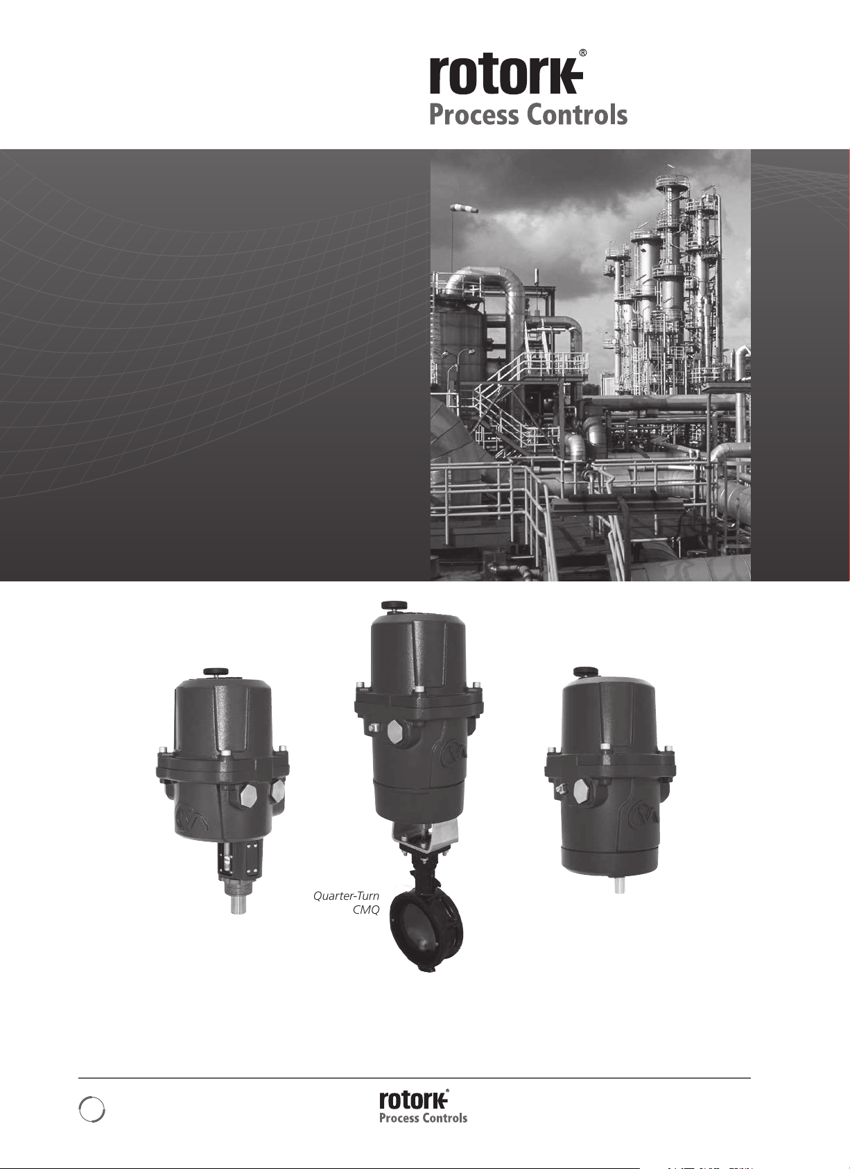
Linear, Rotary and Quarter-Turn
Control Valve Actuators
Contents
Section Page
Introduction 3
General Information 4
Hazardous Area Approvals 9
Installation & Setup 11
Mounting the Actuator 15
Electrical Installation 23
Basic Setup 26
Menu Structure 43
Status (Alarms), Fault History & Default Menus 44
Fault History Menu 46
Default Menu 48
Advanced Menu 51
Dimensional Drawings 56
Power Ratings 59
Linear CML Rotary CMR
THIS MANUAL CONTAINS IMPORTANT SAFETY
INFORMATION. PLEASE ENSURE IT IS THOROUGHLY
READ AND UNDERSTOOD BEFORE INSTALLING,
OPERATING OR MAINTAINING THE EQUIPMENT.
2
Quarter-Turn
CMQ
DUE TO WIDE VARIATIONS IN THE TERMINAL
NUMBERING OF ACTUATOR PRODUCTS, ACTUAL
WIRING OF THIS DEVICE SHOULD FOLLOW THE PRINT
SUPPLIED WITH THE UNIT.

Introduction
Rotork Process Controls designs, manufactures,
and tests its products to meet many national
and international standards. For these products
to operate within their normal specifications,
they must be properly installed and maintained.
The following instructions must be followed and integrated
with your safety program when installing and using Rotork
Process Controls products:
• Read and save all instructions prior to installing, operating
and servicing this product.
• If you don’t understand any of the instructions, contact
Rotork Process Controls for clarification.
• Follow all warnings, cautions and instructions marked on,
and supplied with, the product.
• Inform and educate personnel in the proper installation,
operation and maintenance of the product.
• Install equipment as specified in Rotork Process Controls
installation instructions and per applicable local and
national codes. Connect all products to the proper
electrical sources.
• To ensure proper performance, use qualified personnel to
install, operate, update and maintain the unit.
• When replacement parts are required, ensure that the
qualified service technician uses replacement parts
specified by Rotork Process Controls. Substitutions may
result in fire, electrical shock, other hazards, or improper
equipment operation.
• Keep all product protective covers in place (except
when installing, or when maintenance is being performed
by qualified personnel), to prevent electrical shock,
personal injury or actuator damage.
• Operation of actuator in an inappropriate fashion
may cause harm or damage to unit or other equipment
surroundings.
Redefining Flow Control
3

General Information
INTRODUCTION
This manual has been produced to enable a competent user
to install, operate, adjust and inspect the Rotork Range of
Compact Control Valve Actuators.
The electrical installation, maintenance and use of these
actuators should be carried out in accordance with the
National Legislation and Statutory Provisions relating to
the safe use of this equipment applicable to the site of
installation.
For the UK: Electricity at Work Regulations 1989 and the
guidance given in the applicable edition of the ‘IEE Wiring
Regulations’ should be applied. Also the user should be fully
aware of their duties under the Health and Safety at Work
Ac t 1974.
For the USA: NFPA70, National Electrical Code
The mechanical installation should be carried out as outlined
in this manual and also in accordance with any relevant
national standard codes of practice. If the actuator nameplate
indicates that it is suitable for use in a Potentially Explosive
Atmospheres (Hazardous Areas) then the actuator is suitable
for use in Zone 1 and Zone 2 (or Div 1 and Div 2) hazardous
area classifications, as defined by the actuator’s nameplate
marking.
Any equipment connected to the actuator should be of
an equivalent (or better) hazardous area certification. The
installation, maintenance and use of the actuator installed in
a hazardous area must be carried out by a competent person
and in accordance with all relevant codes of practice for the
particular Hazardous Area certification.
Any inspection or repair of Hazardous Area approved
actuators should not be undertaken unless it conforms to
National Legislation and Statutory Provisions relating to the
specific Hazardous Area.
®
is applicable.
Only Rotork approved actuator replacement parts should
be used. Under no circumstances should any modification
or alteration be carried out on the actuator, as this could
invalidate the conditions under which its certification was
granted.
Access to live electrical conductors is forbidden in a
Hazardous Area unless it is done under a special permit
to work, otherwise all power should be isolated and the
actuator moved to a non-hazardous area for repair or
attention.
Only persons competent by virtue of their training or
experience should be allowed to install, maintain and repair
Rotork actuators. Work undertaken must be carried out in
accordance with instructions in the manual. The user and
those persons working on this equipment should be familiar
with their responsibilities under any statutory provisions
relating to the Health and Safety of their workplace.
ENCLOSURE MATERIALS
The enclosures on the Rotork Range of Control Valve
Actuators are manufactured from aluminium alloy with
stainless steel fasteners.
The user must ensure that the operating environment and any
materials surrounding the actuator cannot lead to a reduction
in the safe use of, or the protection afforded by, the actuator.
Where appropriate the user must ensure the actuator is
suitably protected against its operating environment.
Should further information and guidance relating to the safe
use of the Rotork Control Valve Actuator Range be required,
it will be provided on request.
4

General Information
GENERAL ACTUATOR DESCRIPTION
Building on Rotork’s historical success with innovative
technology, the CMA offers a highly accurate and responsive
method of automating control valves and pumps without the
complexity and cost of a pneumatic supply.
With a minimum resolution of 0.2% of full stroke for Linear
& Quarter-turn units and 0.6% of full stroke for Multi-turn,
the Rotork CMA range helps to maximize product quality
and plant capacity.
CMA range actuators are self contained, purpose designed
and built for continuous remote electrical operation of
control valves.
CMA range of actuators delivers a series of sizes suitable
for almost all linear, quarter- turn and rotary control valve
and pump applications requiring exact position control and
unrestricted continuous modulation.
Refer to Hazardous Area Approval section for further detail
concerning approved actuators
CML - Linear
The CML is a high precision linear actuator. It is capable of
producing up to 750 pounds of force and a maximum of 2
inch stroke length at a speed of up to .063 inches per second.
NOTE: Thrust and Speed are dependant on frame size.
See page 7 for full details.
CMQ - Quarter-Turn Actuators
The CMQ is a high precision quarter-turn actuator capable
of producing between 250 to 1000 inch pounds at speeds
between 10 to 22 seconds 90 degree operating times.
NOTE: Torque and operating times are dependant on
frame size.
See page 7 for full details.
CMR - Rotary
The CMR is a high precision rotary unit with torque outputs
between 50 to 250 inch pounds at output speeds between
5 to 12 RPM depending on frame size.
NOTE: Torque and operating times are dependant on
frame size.
The actuator comprises:
• Absolute Encoder
• LCD User Interface
• DC brushless electric motor
• Simple, maintenance free geartrain
• Motor controller with travel and
torque/thrust adjustment
• Manual Overide
• Hazardous area certification meeting
international and national requirements
Redefining Flow Control
5
General Information
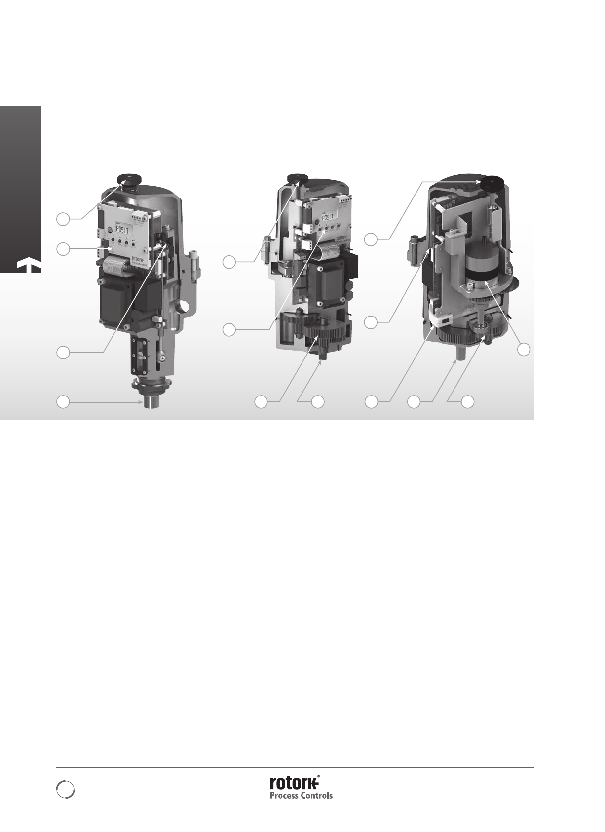
Advanced Engineering
CML
Linear Actuator
4
2
1
6
CMQ
Quarter-Turn Actuator
4
2
5 6
CMR
Rotary Actuator
4
2
61
3
5
1 Encoder Technology
The CMA utilizes absolute encoder technology where a
unique digital code corresponds to the angular position
(CMQ), stroke length (CML) or rotary (CMR) position of the
actuator.
To achieve high resolution, the position sensor location
eliminates any backlash effect in the gearing. The sensor is
a 12-bit rotary magnetic encoder, fitted at the output gear
stages, removing any internal backlash effect that may exist in
the drive train.
2 User Interface
The CMA LCD display is a 6-character, single line display.
Two graphic symbols are provided for notification of alarm
conditions. The menu style is an intuitive common tree
structure similar in function to the menu system used on PCs.
Two relays can be programmed to close upon reaching a
desired position or any other available fault condition among
the programmable options.
3 DC Brushless Motor
The CMA uses a high efficiency, continuous rated, brushless
DC motor. This allows maintenance-free operation even with
continuous unrestricted modulation duty.
4 Hand Drive
A hand drive mechanism is provided as standard for all CMA
actuators to allow manual operation of the valve. Pressing
down on the hand-knob shaft allows it to engage a gear
in the upper section of the drive train. Releasing causes the
spring to disengage the gear.
5 Geartrain
The simple yet durable high efficiency spur gear drive is
lubricated for life. It has proven high reliability.
The CML and CMQ standard build is capable of resisting any
back drive from the load, up to 125% of the rated thrust or
torque of the actuator.
6 Output Drive
The CMQ base conforms to MSS SP-101 or ISO5211.
The CMR and CML may be adapted to suit individual valves.
6
General Information
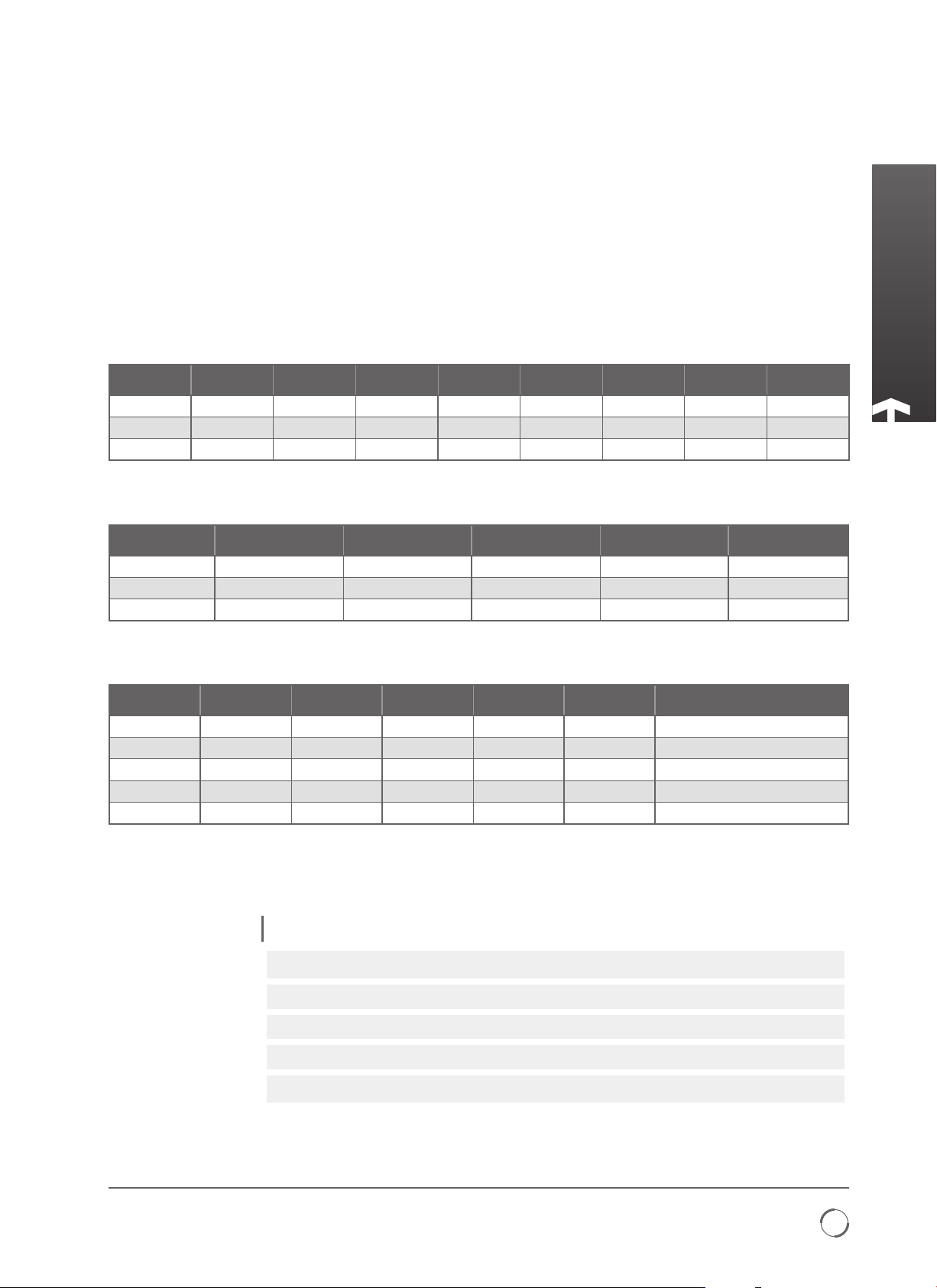
Mechanical Performance
The rated force (thrust or torque) for each size of actuator is
detailed below. The minimum settable force is 40% of the
maximum rated. Operating time tolerance +/-10%.
The CML and CMQ can resist backdriving forces from the
valve up to 125% of rated load without movement.
CML: Linear Actuator
All CMA actuators are factory calibrated.
Model
CML-100 40 177.9 100 444.8 0.25 6.35 1.5 38.1
CML-250 100 444.8 250 1112 0.125 3.18 1.5 38.1
CML-750 300 1334.5 750 3336.2 0.063 1.68 2 50.8
Min Thrust
(lbf)
Min Thrust
(N)
Max Thrust
(lbf)
Max Thrust
(N)
Speed
(inches/sec)
Speed
(mm/sec)
Stroke
(inches)
CMQ: Quarter-Turn Actuator
Model
CMQ-250 100 11.3 250 28.2 10
CMQ-500 200 22.6 500 56.5 15
CMQ-1000 400 45.2 1000 113.0 22
Min Torque
(lbf.in)
Min Torque
(Nm)
Max Torque
(lbf.in)
Max Torque
(Nm)
Time for Quarter-
Turn (secs)
CMR: Rotary Actuator
Model
CMR-50 20 2.3 50 5.6 11
CMR-100 40 4.5 100 11.3 10
CMR-125 50 5.6 125 14.1 18
CMR-200 80 9.0 200 22.6 5
CMR-250 100 11.3 250 28.2 10
Min Torque
(lbf.in)
Min Torque
(Nm)
Max Torque
(lbf.in)
Max Torque
(Nm)
Speed (RPM)
Total turns
available
90º to 320 turns in 2º
90º to 320 turns in 2º
90º to 320 turns in 2º
90º to 320 turns in 2º
90º to 320 turns in 2º
Stroke
(mm)
increments
increments
increments
increments
increments
Vibration, Shock and Noise
CMA actuators are suitable for applications where vibration and shock severity does not exceed the following:
Type Level
Plant induced vibration
1 g RMS total for all vibration within the frequency range of 10 to 1000Hz.
Shock 5 g peak acceleration.
Seismic 2 g acceleration over a frequency range of 1 to 50 Hz if it is to operate during and after the event.
5 g over a frequency range of 1 to 50 Hz if it is only required to maintain structural integrity.
Emitted noise
Levels quoted are those present at the actuator mounting interface. It should be noted that the effects of vibration are cumulative and therefore an actuator
subjected to significant levels may have reduced life.
Independent tests have shown that at 1 m generated noise does not exceed 61 db (A).
Redefining Flow Control
7

General Information
RECEIVING / INSPECTION
Carefully inspect for shipping damage. Damage to the
shipping carton is usually a good indication that it has
received rough handling. Report all damage immediately to
the freight carrier and Rotork Controls Ltd.
Unpack the product and information packet taking care to
save the shipping carton and any packing material should
return be necessary. Verify that the items on the packing list
or bill of lading agree with your own documentation.
Rotork cannot accept responsibility for deterioration caused
on-site once the covers are removed. Every Rotork actuator
has been fully tested before leaving the factory to give
years of trouble free operation providing it is correctly
commissioned, installed and sealed.
WARNING
Before installing the actuator, make sure that it is
suitable for the intended application. If you are unsure
of the suitability of this equipment for your installation
consult Rotork prior to installation.
WARNING: ELECTRIC SHOCK HAZARD
Installation and servicing must be performed only by
qualified personnel.
WARNING: ELECTROSTATIC DISCHARGE
This equipment houses static sensitive devices. To
protect the internal components never touch the
printed circuit boards without using electrostatic (ESD)
control procedures.
STOR AGE
If your actuator cannot be installed immediately store it in a
dry place until you are ready to connect incoming cables.
If the actuator has to be installed but cannot be cabled it is
recommended that any plastic cable entry plugs are replaced
with PTFE sealed metal plugs.
EQUIPMENT RETURN
If your Rotork actuator has been correctly installed and sealed
it will give years of trouble free service.
Should you require technical assistance or spares, Rotork
guarantees the best service in the world. Contact your local
Rotork representative or the factory direct at the adress on
the nameplate, quoting the actuator type and serial number.
ABBREVIATIONS USED IN THIS MANUAL
A Ampere
AC Alternating Current
°C Degrees Celsius
CW Clockwise
ACW Anti-clockwise
CCW Counter-clockwise
DC Direct Current
°F Degrees Fahrenheit
G Earth Ground
Hz Hertz
kg Kilogram
L Line (power supply)
lbf Pounds Force
lbf.in Inch Pounds
lbf.ft Foot Pounds
mA Milliamp
mfd Microfarad
mm Millimeters
N Newton (force)
NEMA National Electrical
Manufacturing
Association
Nm Newton Meter
NPT National Pipe Thread
PCB Printed Circuit Board
PL Position Limit switch
RPM Revolutions per
Minute
SEC Second
V Volts
VA Volt Amps
VAC Volts AC
VDC Volts DC
VR Variable Resistance
W Watt
WARRANTY INFORMATION
Warranty: Subject to the following, Rotork Process Controls
expressly warrants the products manufactured by it as
meeting the applicable Rotork Process Controls product
specifications and that such products are free from defects
in material and workmanship for a period of one (1) year
from the date of delivery. The foregoing is the sole and
exclusive warranty made by Rotork Process Controls with
respect to the products. Rotork Process Controls makes no
other warranties, either express or implied (including, without
limitation, warranties as to merchantability or fitness for a
particular purpose). The purchaser retains responsibility for
the application and functional adequacy of the offering.
See Rotork Process Controls’s General Conditions of Sale Product, for complete warranty information.
IDENTIFICATION LABEL
An identification label is attached to each actuator. When
ordering parts, requesting information or service assistance,
please provide all of the label information. You must supply
the serial number with all enquiries.
ROTORK PROCESS CONTROLS
MILWAUKEE, WI, USA.
www.
Serial number
Wiring diagram
Actuator type
Output max.
Enclosure
Actuator supply
Rated current
M1895423942
M00-00
CML-250
2224 N
IP67
120/240
.com
0518
1
Amp
Unit weight
Year of manufacture
8
2012
47568-1
Kg
Fig 9.1 Actuator identification label.
8

Hazardous Area Approvals
The CMA is suitable for both indoor and outdoor use up to
an altitude of 5,000 m and is watertight to IP67.
Refer to the actuator nameplate for it’s specific
approval details.
European - Hazardous Area ATEX (94/9/EC) II 2 c T4 GD
Ex d IIB T4 Gb, Ex t IIIC T120 °C Db
EN60079-0 and EN60079-1
Ambient Temperature Range:
-20 to +65 °C (-4 to +150 °F)
*Option -40 to +60 °C (-40 to +140 °F)
Ex d IIC T4 Gb, Ex t IIIC T120 °C Db
EN60079-0 and EN60079-1
Ambient Temperature:
Range -20 to +65 °C (-4 to +150 °F)
*Option -40 to +60 °C (-40 to +140 °F)
International - Hazardous Area IECEx
Ex d IIB T4 Gb, Ex t IIIC T120 °C Db
IEC60079-0 and IEC60079-1
Ambient Temperature Range:
-20 to +65 °C (-4 to +150 °F)
*Option -40 to +60 °C (-40 to +140 °F)
Ex d IIC T4 Gb, Ex t IIIC T120 °C Db
IEC60079-0 and IEC60079-1
Ambient Temperature Range:
-20 to +65 °C (-4 to +150 °F)
*Option -40 to +60 °C (-40 to +140 °F)
USA - Hazardous Area
FM. Explosionproof, Class I, Div 1, Groups C & D, T4
Ambient Temperature Range:
-20 to +65 °C (-4 to +150 °F)
*Option -40 to +60 °C (-40 to +140 °F)
FM. Explosionproof, Class I, Div 1, Groups C & D, T4
Ambient Temperature Range:
-20 to +65 °C (-4 to +150 °F)
*Option -40 to +60 °C (-40 to +140 °F)
FM. Dust Ignitionproof, Class II, Div 1, Groups E, F & G, T4
Ambient Temperature Range:
-20 to +65 °C (-4 to +150 °F)
*Option -40 to +60 °C (-40 wto +140 °F)
Note: A start corresponds to 1% position change on Linear
and Quarter-turn variants and 36º for multi-turn variants.
Redefining Flow Control
9

Hazardous Area Approvals
Special Conditions For Safe Use (ATEX & IECEx approved actuators)
In accordance with clause 5.1 of IEC/EN 60079-1, the critical dimensions of the flamepaths are:
CML-100/250
Flamepath Maximum Gap (mm) Maximum Width L (mm)
Lid/base 0.15 12.8
Base/pinion shaft 0.145 13.5
Base/feedback shaft bush -0.02 13.7
Feedback shaft bush/feedback shaft 0.06 13.7
Handknob shaft/lid 0.1 25.9
CMQ-250/500
Flamepath Maximum Gap (mm) Maximum Width L (mm)
Lid/base 0.15 12.8
Base/pinion shaft 0.235 29.8
Base/feedback shaft bush -0.02 13.7
Feedback shaft bush/feedback shaft 0.06 13.7
Handknob shaft/lid 0.1 25.9
CMR-50/100/200
Flamepath Maximum Gap (mm) Maximum Width L (mm)
Lid/base 0.15 12.8
Base/pinion shaft 0.235 29.8
Base/output shaft 0.145 12.8
Handknob shaft/lid 0.1 25.9
CML-750
Flamepath Maximum Gap (mm) Maximum Width L (mm)
Lid/base 0.15 12.8
Base/pinion shaft 0.235 37.3
Base/feedback shaft bush -0.02 13.7
Feedback shaft bush/feedback shaft 0.06 13.7
Handknob shaft/lid 0.1 25.9
CMQ-1000
Flamepath Maximum Gap (mm) Maximum Width L (mm)
Lid/base 0.15 12.8
Base/pinion shaft 0.235 37.3
Base/feedback shaft bush -0.02 13.7
Feedback shaft bush/feedback shaft 0.06 13.7
Handknob shaft/lid 0.1 25.9
CMR-125/250
Flamepath Maximum Gap (mm) Maximum Width L (mm)
Lid/base 0.15 12.8
Base/pinion shaft 0.235 37.3
Base/ourtput shaft 0.145 13
Handknob shaft/lid 0.1 25.9
Note: Negative Sign denotes an interference fit.
WARNING
The equipment utilises a non-metallic outer coating
and has a potential static hazard. Clean only with a
damp cloth.
10

Installation & Setup
COMMISSIONING
The Rotork CMA Range of actuators provide simple, safe and
rapid commissioning.
TOOLS & EQUIPMENT REQUIRED
(General Guideline Only)
Top Cover Fixings - 6mm Allen Wrench
Electrical Connections - Terminal Screw Driver
Command & Feedback - 4 to 20 mA Command
source/meter
Actuator to Valve fixings - As Required.
CAUTION
It is essential that the setup procedure is carried
out when the valve is not under working process
conditions, as full valve movement may occur.
IMPORTANT
It is essential that the actuator is mounted correctly to
the valve!
The height of the yoke or pillar and mounting plate, in
relation to the top of the valve spindle is critical to ensure
full stroke movement of the valve.
The Installation & Setup will include the following steps:
1. Ensure valve position is noted and safe (Offline).
2. Actuator output shaft is retracted. (Linear Units only)
3. Actuator is in closed position. (Rotary Units only).
4. Mount and align actuator to valve.
5. Set limits of travel.
6. Configure control and indication parameters
Redefining Flow Control
11
Installation & Setup
INSTALLING YOUR ACTUATOR
The following instructions must be followed and integrated
into your safety program when installing and using Rotork
products.
• Read and save all instructions prior to installing,
operating and servicing this product.
• If you don’t understand any of the instructions contact
Rotork for clarification.
• Follow all warnings, cautions and instructions marked on
and supplied with the product.
• Inform and educate personnel in the proper installation,
operation and maintenance of the product.
Install equipment as specified in Rotork installation
instructions and as per applicable local and national
codes of practice. Connect all products to the proper
electrical sources.
• To ensure proper performance, use only qualified
personnel to install, operate, update and maintain
the unit.
• When replacement parts are required, ensure that the
qualified service technician uses only replacement parts
specified by Rotork.
• Substitutions will invalidate any hazardous area
certification and may result in fire, electrical shock, other
hazards or improper operation.
• Keep all product protective covers in place (except during
installation or maintenance by qualified personnel)
to prevent electrical shock, personal injury or damage
to equipment.
• Operation of the actuator in an inappropriate fashion
may cause harm or damage to the unit or surrounding
equipment.
The end user should take care when assessing the local
ambient temperature to take into account the heat from any
connecting pipe-work or inherent heat from process plant etc.
WARNING
Before installing the actuator, make sure that it is suitable for
the intended application. If you are unsure of the suitability
of this equipment for your installation consult Rotork prior to
installation.
WARNING: ELECTRIC SHOCK HAZARD
Installation and servicing must be performed only by
qualified personnel.
WARNING: ELECTROSTATIC DISCHARGE
This equipment houses static sensitive devices. To protect the
internal components never touch the printed circuit boards
without using electrostatic (ESD) control procedures.
WARNING: ENCLOSURE MATERIALS
CMA actuator castings are manufactured from aluminium
alloy with stainless steel fasteners. The user must ensure that
the operating environment and any materials surrounding the
actuator cannot lead to a reduction in the safe use of, or the
protection afforded by the actuator. Where appropriate the
user must ensure the actuator is suitably protected against its
operating environment.
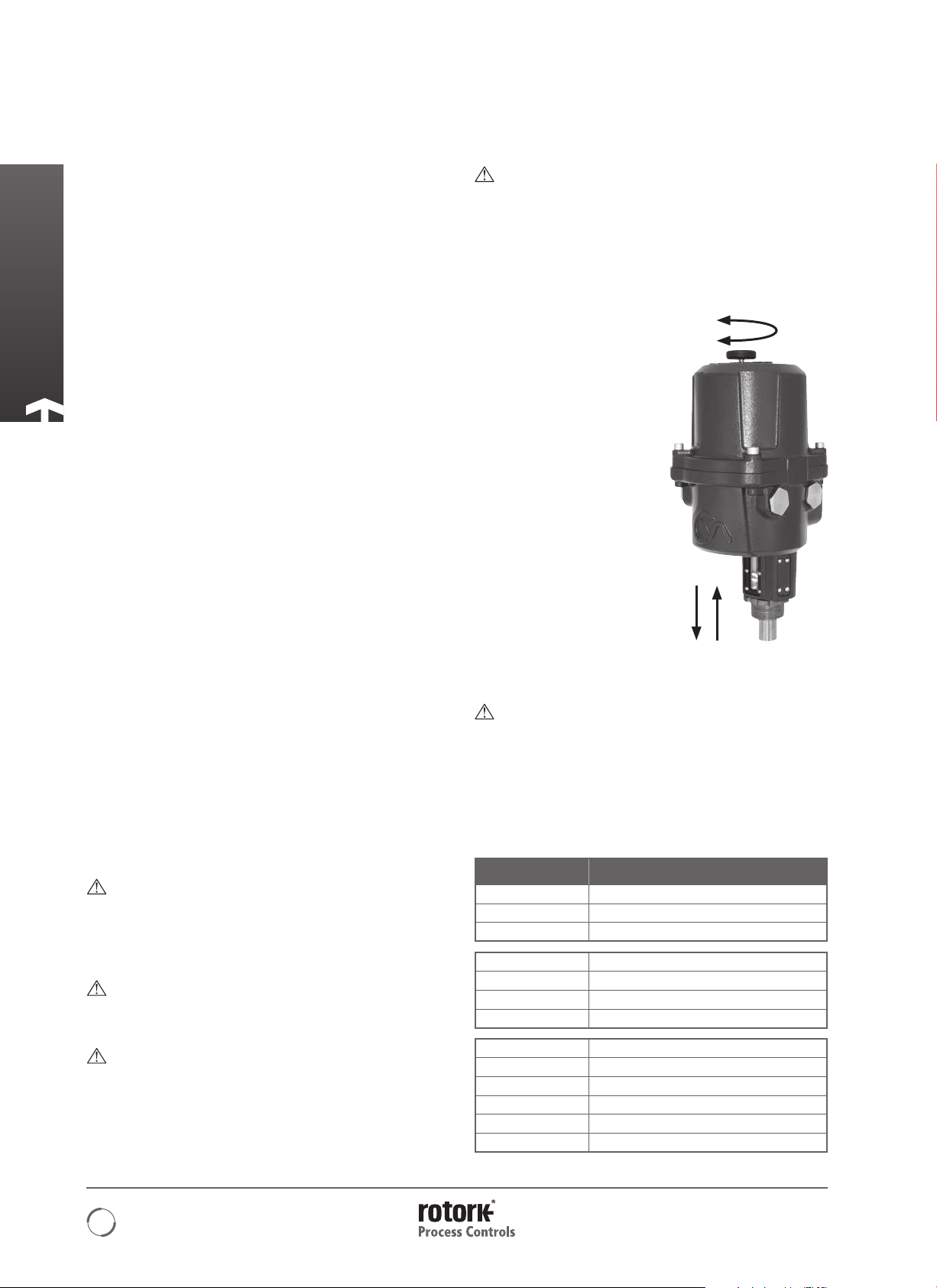
HANDWHEEL OPERATION
The handwheel is located on
the top cover of the CMA (All
Variants). Push and hold the
hand wheel down and rotate
to extend/retract or rotate the
actuator output drive.
Fig. 12.1
Verify direction of output shaft rotation for clockwise
operation of the handwheel. (Varies with frame size).
WARNING: OPERATING BY HAND
Note that under no circumstances should any
additional lever device such as a wheel key or wrench
be applied to the hand-wheel in order to develop more
force when closing or opening the valve as this may
cause damage to the valve and/or actuator. It may also
cause the valve to become stuck in the seated or back
seated position.
Model
CMA - Linear Extend or Retract
CML-100/250 Retract
CML-750 Extend
CMA - Quarter-turn
CMQ-250 Anticlockwise
CMQ-500 Anticlockwise
CMQ-1000 Anticlockwise
CMA -Rotary
CMR-50 Clockwise
CMR-100 Clockwise
CMR-125 Clockwise
CMR-200 Clockwise
CMR-250 Clockwise
Output When Hand Knob
is Turned Clockwise
12
Installation & Setup
STANDARD ACTUATOR
The standard actuator is not supplied with local control knobs
or external display. Removal of top cover assembly is required
to adjust configuration parameters and facilitate connection
of power and field wiring.
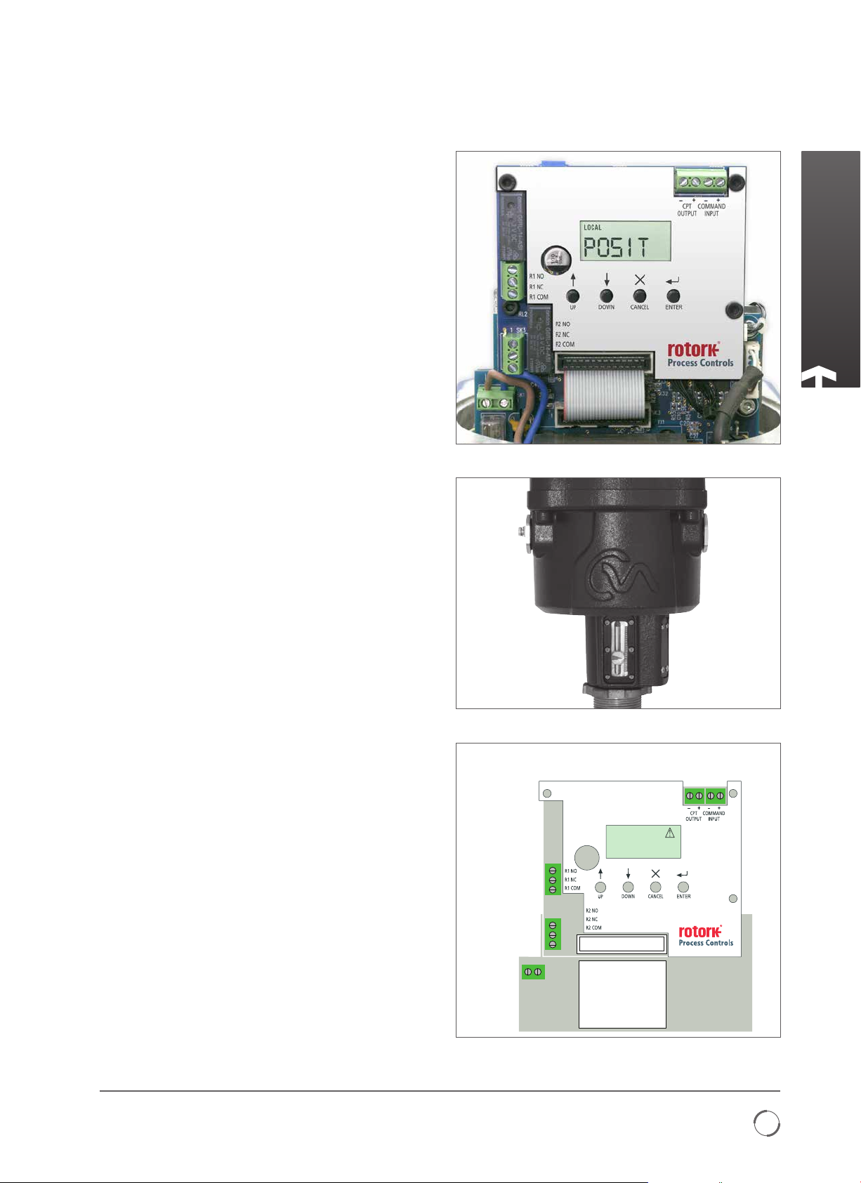
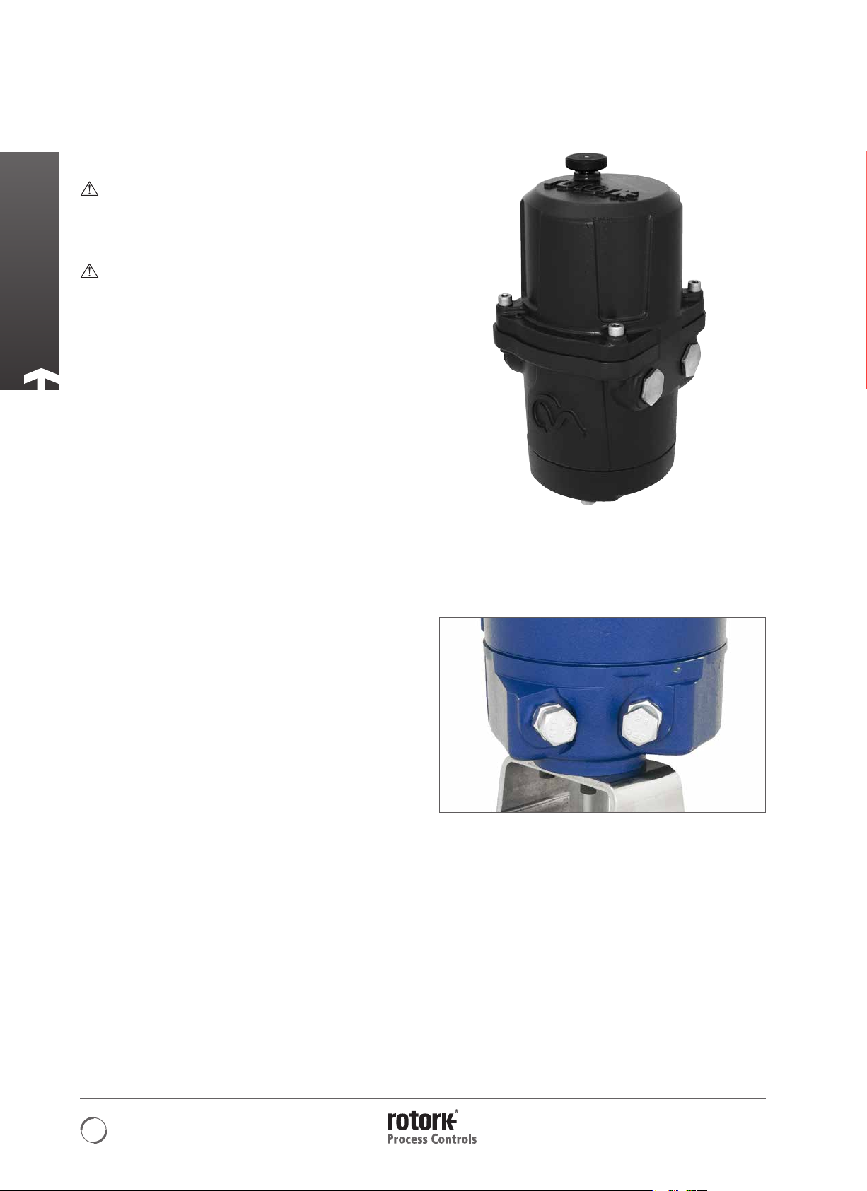
LOCAL INDICATOR
CML has one indicator as standard. All variants can be fitted
with optional extended cover with local display window.
Fig. 13 .1
MAIN PRINTED CIRCUIT BOARD (PCB) LAYOUT
Redefining Flow Control
MainsInput
(Earth stud
located behind)
Fi g . 13.2
Note: Current Position Transmitter(CPT )isloop powered.
Relay1:
N/O
N/C
Common
Relay2:
N/O
N/C
Common
LN
Neutral
Live
Fig 13.3 Main PCB.
REMOTE
POS I T
CPT Feedback-
CPT Feedback+
Demand -
Demand +
13
Installation & Setup
LCD DISPLAY
The main PCB has a LCD Display used to show STATUS and
configuration information
On power up the default screen is the POSIT parameter.
The actuator will indicate Local or Remote mode selected in
top left hand corner of the LCD.
See Basic Setup Mode for details.
SETUP PUSHBUTTONS
Four push button switches are located on the main PCB below
its LCD Display and are used to view and change the actuator
configuration parameters.
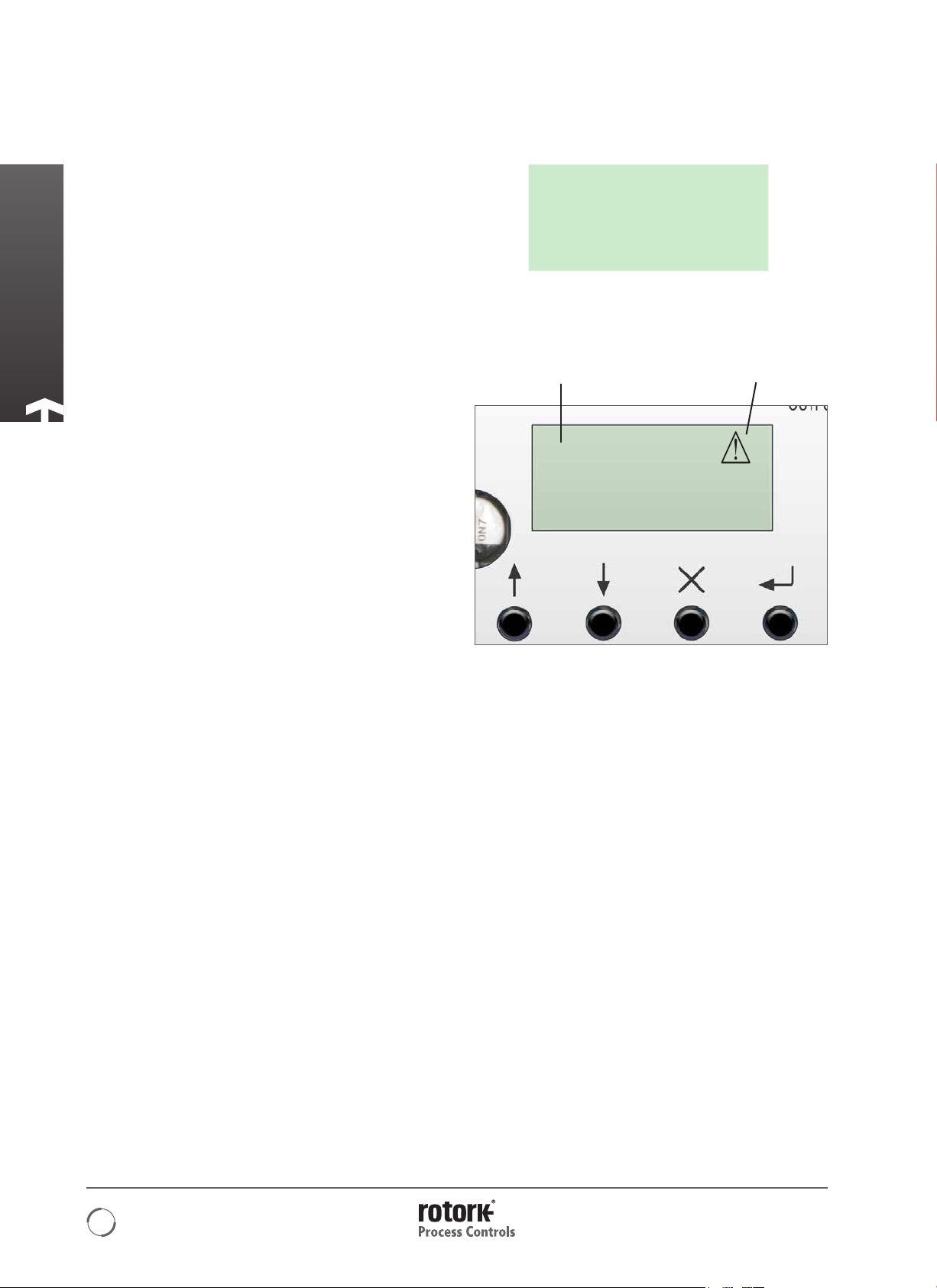
The Switch Functions are as follows:
‘UP’
Used to navigate menus in view mode. Increase parameter
values in Edit Mode.
‘DOWN’
Used to navigate menus in view mode. Decrease parameter
values in Edit Mode.
‘MODE/CANCEL’
Used to exit and go to previous Menu.
LOCAL
POS I T
Fig. 14.1
Remote Mode Selected Alarm Active
REMOTE
POS I T
ENTER
Used to enter and save changes to configuration parameters
‘UP’ ‘DOWN’ ‘MODE/CANCEL’ ENTER
Fi g. 14. 2
14
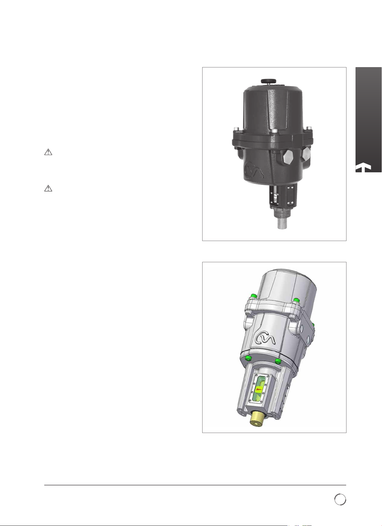
Mounting the Actuator
The CMA Actuator is available for Linear, Quarter-turn or
Rotary valves, dampers or other devices.
Each of these applications may require different methods of
mounting the actuator to the valve.
Typical examples only are described in this publication and do
not cover all possible variants of valve types.
CML - LINEAR UNIT - MOUNTING
CAUTION
It is essential that the actuator mounting procedure is
carried out when the valve is not under working process
conditions, as full valve movement may occur.
IMPORTANT
It is essential that the actuator is mounted correctly to
the valve.
The height of the yoke or pillar and mounting plate, in
relation to the top of the valve spindle is critical to ensure full
stroke movement of the valve.
The Installation & Setup will include the following procedures:
1. Ensure Valve is closed and safe (Offline).
2. Actuator output shaft is retracted.
3. Mount and align actuator to valve.
4. Carry out Basic Setup
CM L-10 0 & CML-2 50
CM L-75 0
Redefining Flow Control
15
Mounting the Actuator
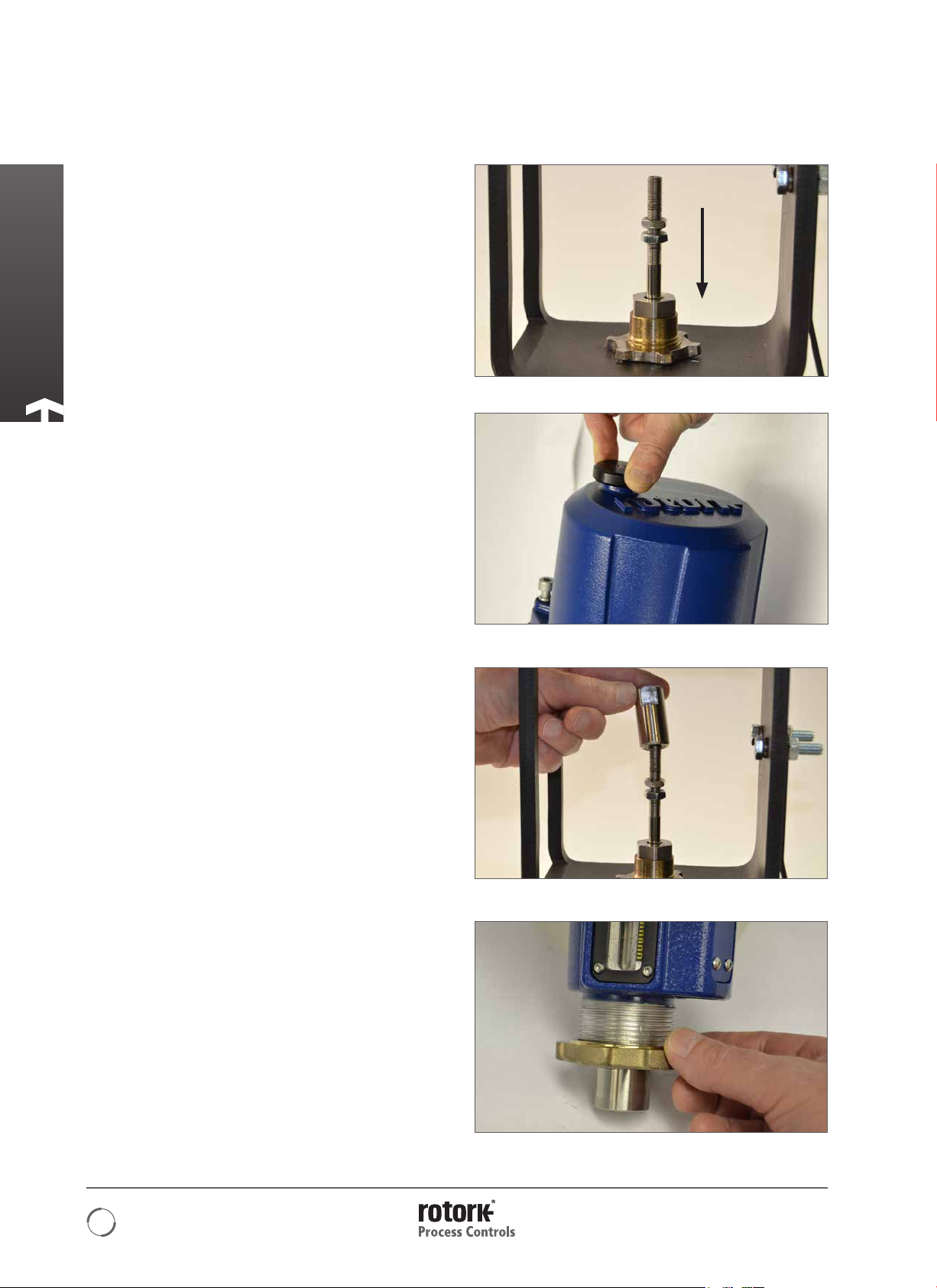
Move Valve stem to the closed position
To enable the actuator to be installed correctly the valve must
be in the closed (down) position to allow fitting of the valve
stem/actuator coupling.
Actuator Output Shaft
The actuator is supplied with the output shaft in the fully
retracted position. If the output shaft is in the extended
position it may be necessary to manually operate the actuator
using the hand wheel to the retracted position to allow
installation. Push and turn the hand wheel to retract the
output shaft.
Fig. 16.1
Valve Stem Coupling
Machine the valve stem to actuator output shaft coupling
adaptor to suit. (NOT SUPPLIED)
Fit the coupling to the valve stem. It may be necessary to use
a locking nut to eliminate any backlash.
Leave the coupling loose and free to rotate at this stage.
CML-100 & CML-250 Units Only
Remove the locking ring from the base of the actuator and
position the unit on to the valve mounting flange.
CML-750 Units
Position the actuator on to its mounting flange, fit four off
fixings but do not fully tighten at this stage.
Fig. 16.2
Fig. 16.3
16
Fig. 16.4
Mounting the Actuator
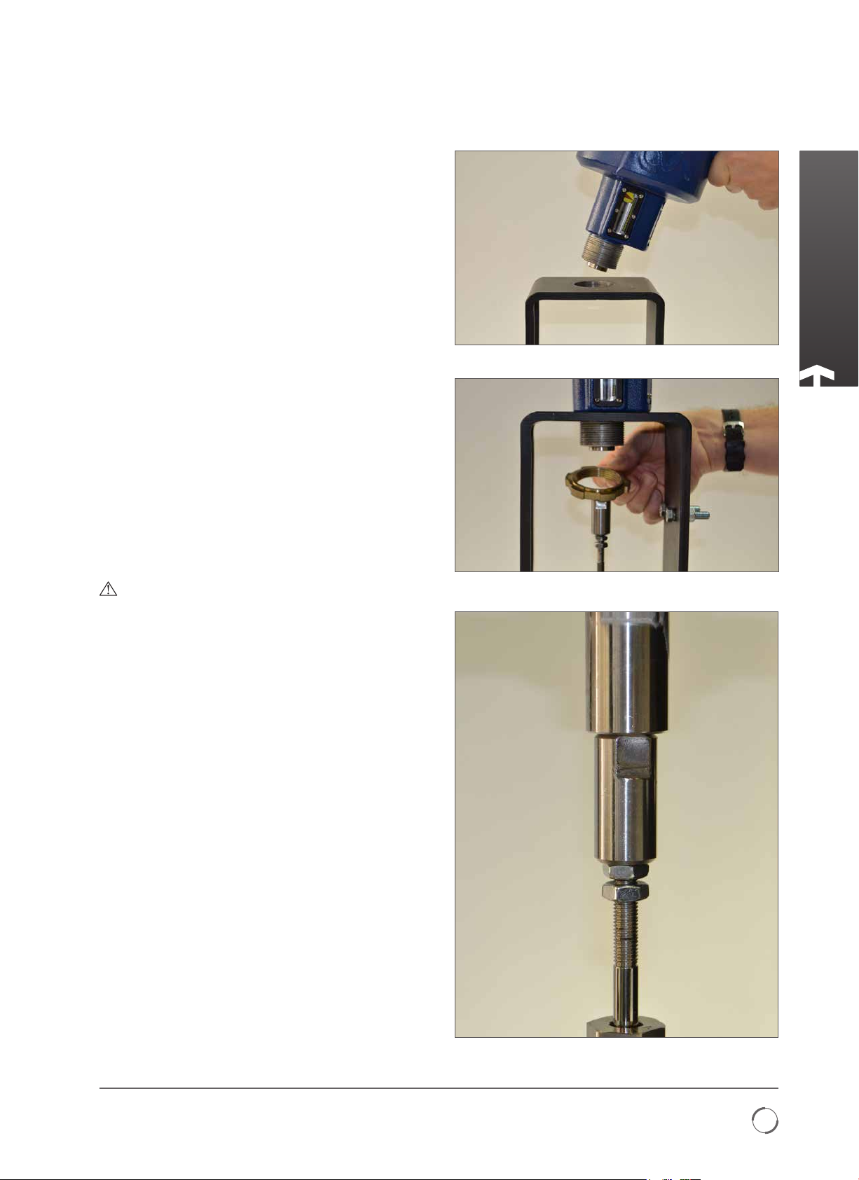
Replace the locking ring.
DO NOT FULLY TIGHTEN AT THIS STAGE.
Extend the actuator output shaft to bring the end of the shaft
and the coupling together. Rotate the coupling as required
to get a good firm contact between the valve stem and the
output shaft.
Adjust and tighten locking nut(s) if fitted on valve stem side of
the coupling. Ensure that the actuator is centrally aligned with
the valve stem.
If the actuator output shaft reaches its fully extended position
it will be necessary to retract the actuator shaft a sufficient
distance to allow adjustment of the coupling to ensure a tight
shut off in thrust seating valves.
Fig. 17.1
WARNING
It is critical that there is correct alignment between
actuator output shaft and the valve stem.
Note: Mis-alignment will result in increased mechanical
wear and possible damage to the valve stem.
CML-100 & CML-250 Units only
Tighten the locking ring fully to secure the actuator in
position. Push and turn the manual override to verify correct
operation of the valve.
CML-750 Units
Tighten the four fixings fully.
Fi g . 17. 2
Go to page 23 for electrical installation and basic setup
instructions.
Redefining Flow Control
Fi g . 17. 3
17
Mounting the Actuator
CMQ - QUARTER-TURN UNIT - MOUNTING
CAUTION
It is essential that mounting procedure is carried out
when the valve is not under working process conditions,
as full valve movement may occur.
IMPORTANT
It is essential that the actuator is mounted correctly to
the valve, damper or other device.
The Installation & Setup will include the following procedures:
1. Prepare the Drive Coupling.
2. Ensure Valve position is noted and safe (Offline).
3. Mount and align actuator to valve.
4. Adjust Actuator Stop Bolts.
5. Carry out Basic Setup.
ACTUATOR STOP BOLTS
The Quarter-turn CMQ actuators have two end of travel stop
bolts adjustable between 80 to 100 degrees of travel rotation.
The Stop Bolts are set to a nominal 90 degrees of travel at
the factory. These must be adjusted to suit the required valve
travel BEFORE attempting to set the electrical travel limits.
The Clockwise end of travel stop bolt is on the right as viewed
in Fig. 18.2.
Fig. 18.1
Fig. 18 .2
18

Mounting the Actuator
Securing Actuator to Valve
Before fitting actuator to the valve ensure that the actuator
and valve are in the same position. The position of the
actuator can be confirmed by using the hand wheel
A suitable mounting flange conforming to ISO 5211 or USA
standard MSS SP-101 depending on the actuator supplied
must be provided to mount the unit to the valve top works
assembly.
Actuator to mounting flange assembly fixings must conform
to Material Specification ISO Class 8.8. Delta GZ coated Grade
A4 stainless steel fixings are recommended.
Actuator is supplied with a square output drive shaft. A
coupling and adaptor bracket is required to mate the actuator
to the valve stem.
Fig. 19.3 shows a typical valve adaptation kit.
Fit suitable mounting brackets and adaptors to the valve body.
Ensure that valve stem and actuator output shaft are in the
same position (Open or Closed).
Align the actuator output shaft with stem adaptor
Position actuator on to the valve mounting flange. It may be
necessary to adjust the position of the actuator to enable
alignment of the fixing bolts.
Tighten base fixings in accordance with table 2.
Fig. 19.1
Fig. 19.2
Thread Size
5/16 UNC 14 9.5
M8 14 9.5
Push and turn the manual override to verify correct operation
of the valve.
Refer to the table on page 12.
Tor que N m
Table 2
Torque lbf.ft
Fig. 19.3
Redefining Flow Control
Fig. 19.4
19

Mounting the Actuator
Stop Bolt Adjustment
It is recommended that stop bolt adjustment be carried out
by the valvemaker/supplier before the valve is fitted in to the
pipework.
Once installed the valvemaker/supplier should be consulted
before stop bolt re-adjustment is carried out. After setting or
adjustment of stop bolts the actuator limits must be reset.
The CMA stop bolts are located on the lower body assembly.
The stop bolt adjustment allows +/- 5
each end position. Screwing bolts in reduces the range of
movement, out increases range of movement.
For clockwise closing valves the right hand bolt is the closed
stop as shown in Fig 20.2. The left hand bolt is the open stop.
Stop bolts are factory set to give a nominal travel of 90
degrees travel.
Adjustment for non seating valve types
For closed and open stop position adjustment. Undo stop bolt
locknut. Move actuator and valve to the required stopping
position (it may be necessary to unscrew stop bolt to allow
more travel). Screw stop bolt in until a stop is felt. Tighten
stop bolt lock nut.
o
variation of travel at
Fig. 20.1
Adjustment for seating valve types
Undo stop bolt locknut. Move actuator and valve to the
required stopping position (it may be necessary to unscrew
stop bolt to allow more travel). Screw stop bolt in until a stop
is felt and then back off by 1 to 3 turns. Tighten stop bolt lock
nut.
Go to page 23 for electrical installation and basic setup
instructions.
Fig. 20.2
Fig. 20.3
20
Fig. 20.4

Mounting the Actuator
CMR - ROTARY (MULTI-TURN ) UNIT MOUNTING
(NON THRUST)
CAUTION
It is essential that mounting procedure is carried out
when the valve is not under working process conditions,
as full valve movement may occur.
IMPORTANT
It is essential that the actuator is mounted correctly to
the valve, damper or other device.
The Installation & Setup will include the following procedures:
1. Prepare the Drive Coupling.
2. Ensure Valve position is noted and safe (Offline).
3. Mount and align actuator to valve/pump.
4. Carry out Basic Setup.
A suitable mounting flange must be provided to mount
the unit to the valve top works assembly. Mounting flange
assembly fixings must conform to Material Specification ISO
Class 8.8. Delta GZ coated Grade A4 stainless steel fixings
are recommended. CMA Rotary actuators are supplied
with base assembly suitable for Non Thrust applications
requiring between 180 degrees and 320 turns operation.
For applications that require thrust to be taken by the actuator
apply to Rotork Process Controls.
Drive Coupling
Machine and fit coupling adaptor to the actuator output shaft
and secure appropriately.
Align and Mount Actuator
Ensure that the actuator/stem coupling is aligned correctly
with the stem of the valve or actuated device. Mount the
actuator to the flange adaptor, ensure that the actuator is
central and there is no mis-alignment between the coupling
and shaft.
Fig. 21.1
Fi g. 21.2
Redefining Flow Control
Fi g. 21.3
Fi g. 21.4
21

Mounting the Actuator
CMR - ROTARY (MULTI-TURN) UNIT MOUNTING
(NON THRUST)
Tighten base fixings in accordance with table 3.
Thread Size
5/16 UNC 14 9.5
M8 14 9.5
Push and turn the manual override to verify correct operation
of the valve.
Go to page 23 for electrical installation and basic setup
instructions.
Tor que N m
Table 3
Torque lbf.ft
Fig. 2 2.1
Fig. 22.2
22

Installation & Setup
Electrical Installation
Cable Entries
The cable entries are tapped either ¾” NPT or M25. Remove
any transit plugs. Make off cable entries appropriate to the
cable type and size. Ensure that threaded adaptors, cable
glands or conduit are tight and fully waterproof. Seal unused
cable entries with steel or brass threaded plugs.
If the actuator is to be installed in a hazardous area, a suitably
certified cable gland must be fitted with the use of a certified
thread adaptor where appropriate.
Unused entries must be closed with a suitably certified
stopping plug.
Wiring installation must comply with local statutory
regulations.
Connecting to Terminals
The wiring diagram supplied is particular to each actuator and
must not be interchanged with any other actuator. If in doubt
check the wiring diagram number with that on the actuator.
Refer to the wiring diagram to identify functions of terminals.
Check that the supply voltage is the same as that marked on
the actuator nameplate.
Fig. 23.1
Redefining Flow Control
23

Installation & Setup
Electrical Installation
WARNING
Ensure all power supplies are isolated before removing
actuator covers.
Check that the supply voltage agrees with that stamped on
the actuator nameplate. A fused switch or circuit breaker
must be included in the wiring installation of the actuator. The
switch or circuit breaker must be installed as close as possible
to the actuator and shall be marked to indicate that it is the
disconnecting device for that particular actuator. Actuator
must be mounted such that it is not difficult to operate the
disconnecting device.
The actuator must be protected with an over current
protection device rated in accordance with PUB094-001
which details the electric motor performance data for CMA
range actuators.
Earth Ground Connections
A lug is cast adjacent to the conduit entries for attachment of
an external protective Earth (Ground) cable. An internal earth
terminal is also provided. However it must not be used alone
as the protective Earth Connection. See Fig. 24.1.
Fig. 24 .1
Removing Terminal cover
Using a 6 mm Allen key loosen the captive fixings securing the
terminal compartment cover. Do not attempt to lever off the
cover with a screwdriver as this will damage the O-ring seal
and may damage the flamepath on a certified unit.
If necessary locate the two set screws Fig. 24.2 and use them
to lift the cover away from its seat.
Fig. 24.2
Fig. 24.3
24
Fig. 24.4

Installation & Setup
CPT Feedback+
located
Installation Wiring
Route cabling through the most appropriate conduit entry
making sure that cables will not foul on the cover assembly or
internal components after refitting.
Refer to the actuator wiring diagram for connection details.
Terminate the power, control and indication wiring with
appropriate ferrules. Connect wiring to the terminal block
connectors.
Take care to route the wiring away from the spigot housing
on the gearcase.
WARNING:
The actuator must be checked to ensure that the
voltage specified on the actuator identification
nameplate matches the supply voltage.
ROTORK PROCESS CONTROLS
MILWAUKEE, WI, USA.
www.
Serial number
Wiring diagram
Actuator type
Output max.
Enclosure
Actuator supply
Rated current
M1895423942
M00-00
CML-250
2224 N
IP67
120/240
.com
0518
1
Amp
Unit weight
Year of manufacture
8
2012
47568-1
Kg
Fig. 2 5 .1
Fig 25.3 Actuator identification label.
CMA is configured at the factory for use with one of the
following power supply voltages:
110 VAC
115 VAC
Single-Phase
50 Hz / 60 Hz
120 VAC
208 VAC
220 VAC
230 VAC
240 VAC
DC 24 VDC Only
Note: Supply voltage tolerance +/- 10%. Supply frequency tolerance +/- 10%
Relays
Each relay features Normally Open (N/O) and Normally Closed
(N/C) volt-free contacts. Due to the constraints of the Low
Voltage Directive, the maximum allowable voltage that can be
applied to the relay terminals is 150 VAC. For DC however,
the maximum voltage that can be applied is 30 VDC. Rated
Current is 3A.
CPT Feedback
The Loop-powered transmitter provides 4-20 mA signal that
corresponds to position. Loop supply is 24 VDC nominal (20-30
VDC max).
MainsInput
(Earth stud
behind)
Fig. 25.2
Note: Current Position Transmitter (CPT )isloop powered.
Relay1:
N/O
N/C
Common
Relay2:
N/O
N/C
Common
LN
Neutral
Live
Fig 25.4 Main PCB.
REMOTE
POS I T
CPT Feedback-
Demand -
Demand +
Demand
The 4-20 mA command signal is used to control actuator position.
Redefining Flow Control
25

Basic Setup
BASIC SETUP
Basic setup is required once the actuator has been mounted
on to the valve.
Procedures include:
Step 1 Select Local Operation.
Step 2 Set Output Torque/Thrust.
Step 3 Select Action at End of Travel ( Limit or Force).
Step 4 Set Close Limit of Travel.
Step 5 Set Open Limit of Travel.
Step 6 Calibrate Command Signal Zero Setpoint.
Step 7 Calibrate Command Signal Span Setpoint.
The Basic Setup procedure is carried out by using the 4
Pushbutton switches mounted below the LCD display on the
main PCB.
NOTE: SETTINGS CAN ONLY BE CHANGED WITH THE
ACTUATOR SET TO LOCAL OPERATION.
LOCAL
POS I T
SW1
‘UP’
SW2
DOWN
Fig. 2 6 .1
SW3
CANCEL
SW4
ENTER
26

Basic Setup
BASIC MENU STRUCTURE
BASIC
POSITION
SETPOINT
THRUST or TORQUE
LOCAL/REMOTE OPRATION
MANJOG
CLOSE TORQUE/THRUST
OPEN TORQUE/THRUST
CLOSE ACTION
OPEN ACTION
CLOSE LIM
OPEN LIMIT
POSIT
Position
SET PT
Setpoint
THRUST or TORQUE
Thrust Display or
Ouput Torque
LOCAL/REM
Local / Remote Operation
MANJOG
Manual Jog
TORQ/THRUST C
Close Torque/Thrust
TORQ/THRUST O
Open Torque/Thrust
CL ACT
Close Action
OP ACT
Open Action
CL LIM
Close Limit (zero)
OP LIM
Open Limit (span)
FIELD COMMAND SIGNAL 4
FIELD COMMAND SIGNAL 20
DEADBAND
STATUS
FAULT HISTORY
ADV MENU ACCESS
DEFAULTS
CMD4
Field Command Signal4
CMD20
Field Command Signal20
DBAND
Deadband
STATUS
FLTHST
Fault History Access
ADVANC
Advanced Menu
DEFLTS
Default Menu Access
Redefining Flow Control
27

Basic Setup
BASIC SETUP FLOWCHART
STEP 1
SELECT LOCAL
OPERATION
STEP 2
SET OUTPUT
TORQUE/THRUST
STEP 3
SELECT ACTION AT END
OF TRAVEL ( LIMIT OR FORCE)
STEP 4
SET CLOSE LIMIT
OF TRAVEL
STEP 5
SET OPEN LIMIT
OF TRAVEL
STEP 6
CALIBRATE COMMAND
SIGNAL ZERO SETPOINT
STEP 7
CALIBRATE COMMAND
SIGNAL SPAN SETPOINT
STEP 8
DEADBAND
28

Basic Setup
STEP 1
SELECT LOCAL
OPERATION
1. SELECT LOCAL OPERATION
Screen shows the actuator set to Remote operation mode
with alarms active. The Actuator must be set to Local
operation mode before the travel limits can be set.
Using the 4 push button switches mounted below the LCD.
PRESS ‘DOWN’
SETPOINT parameter is now displayed.
Press ENTER to view the current setpoint if required.
REMOTE
POS I T
Fig. 29.1
X
REMOTE
SET PT
Fig. 29.2
PRESS ‘DOWN’
THRUST or TORQUE parameter is now displayed depending
on actuator type CML, CMQ, CMR.
Press ENTER to view current Thrust or Torque output value.
To adjust the Open and Close output Torque or Thrust it will
be necessary to go to the Advanced Menu. If these settings
are correct and do not require adjustment move on to step 4
to set the close limit.
LOCAL/REMOTE parameter is now displayed.
X
REMOTE
THRUST
Fig. 29.3
X
REMOTE
LOCREM
Fig. 29.4
Redefining Flow Control
29

Basic Setup
1. SELECT LOCAL OPERATION
PRESS ENTER
The display now goes in to VIEW mode.
PRESS ENTER
The display now goes in to EDIT mode.
USE the UP or DOWN button to scroll through the menus
until LR LOC is displayed.
X
VIEW
REMOTE
LR REM
Fig. 30.1
X
REMOTE
EDIT
LR REM
Fig. 30.2
X
PRESS ENTER
The actuator is now selected to LOCAL Operation mode and
the change is acknowledged as ‘SAVED’.
Press CANCEL to go back to top level menu.
VIEW
REMOTE
LR LOC
Fig. 30.3
X
LOCAL
EDIT
SAVED
Fig. 30.4
X
30

Basic Setup
STEP 1
SELECT LOCAL
OPERATION
STEP 2
SET OUTPUT
TORQUE/THRUST
2. SET OUTPUT TORQUE/THRUST
Before operating the actuator electrically it may be necessary
to reduce the output torque or thrust of the actuator to
prevent valve becoming jammed at the end of travel during
setup.
Use UP/DOWN buttons until TORQ C is displayed.
Press ENTER to view the Close Output Torque or Thrust value.
Fig 31.2 shows the Closing Torque value set to 40% of the
actuators rated value.
If the set value is correct press CANCEL to return back to
previous menu.
NOTE: The Output Torque or Thrust setting must be
sufficient to operate the valve under full working
process conditions.
X
LOCAL
TORQ
Fig. 31.1
C
X
LOCAL
VIEW
TC 400
Fi g. 31.2
%
Redefining Flow Control
31

Basic Setup
2. SET OUTPUT TORQUE/THRUST
If the Close Torque/Thrust value requires adjustment
press ENTER.
The actuator is now in EDIT Mode and the parameters
can be modified.
Use the UP/DOWN buttons until the correct Torque/Thrust
Value is displayed.
Press ENTER to save the changes. Visually confirm that the
parameter is saved.
X
LOCAL
EDIT
TC 400
Fig. 32.1
X
LOCAL
EDIT
TC 700
Fig. 32.2
X
%
%
Press CANCEL to return to previous menu.
Use UP/DOWN buttons until TORQ O is displayed.
Press ENTER to view the Open Torque or Thrust value.
Fig 32.5 shows the Open Torque value set to 100% of the
actuators rated value.
If the set value is correct press CANCEL to return back to
previous menu.
NOTE: The Output Torque or Thrust setting must be sufficient
to operate the valve under full working process conditions.
Press ENTER to change the Open Torque/Thrust value.
LOCAL
VIEW
SAVED
Fig. 32.3
X
X
LOCAL
TORQ
Fig. 32.4
LOCAL
VIEW
X
C
32
TO 100
Fig. 32.5
%

Basic Setup
STEP 1
SELECT LOCAL
OPERATION
STEP 2
SET OUTPUT
TORQUE/THRUST
2. SET OUTPUT TORQUE/THRUST
The actuator is now in EDIT Mode and the parameters can be
modified.
Use the UP/DOWN buttons until the correct Torque/Thrust
Value Is displayed.
Press ENTER to save the changes. Visually confirm that the
parameter is saved.
NOTE: The Output Torque or Thrust setting must be
sufficient to operate the valve under full working
process conditions.
Press CANCEL to return to previous menu.
LOCAL
EDIT
TO 100
Fig. 3 3.1
X
X
LOCAL
VIEW
SAVED
Fig. 33.2
X
%
STEP 3
SELECT ACTION AT END
OF TRAVEL ( LIMIT OR FORCE)
3. SELECT ACTION AT END OF TRAVEL
The actuator can be configured to stop on position limit at the
end of travel where valves do not require torque or thrust to
be applied to the valve seat.
To provide tight shut off at end of travel the actuator can
be configured to apply its configured torque or thrust to the
valve seat in either direction.
Use the UP/DOWN buttons until CL ACT is displayed.
Press ENTER to view the Close Action setting.
LOCAL
TORQ
Fig. 33.3
LOCAL
CL
ACT
Fig. 33.4
X
X
O
Redefining Flow Control
33

Basic Setup
3. SELECT ACTION AT END OF TRAVEL
CA LIM shows the actuator is set for Position Limit action at
the Closed end of travel.
To change the end of travel action press ENTER.
The actuator is now in EDIT Mode.
Use the UP/DOWN buttons to select the required end of
travel action.
Fig 34.3 shows the Closed End of Travel Action set to FRC
(FORCE) and the set output closing torque or thrust will be
applied to the valve seat at the end of travel.
LOCAL
VIEW
CA LIM
Fig. 3 4 .1
X
LOCAL
EDIT
CA LIM
Fig. 34.2
X
LOCAL
EDIT
Press ENTER to save any changes.
Press CANCEL to return to previous menu.
NOTE Ensure that any changes to parameters are SAVED
before returning to VIEW Mode.
Use the UP/DOWN Buttons to select the Open Action (OP
ACT) and repeat the procedure to select the Action at End of
Travel.
AFTER SAVING ANY CHANGES PRESS CANCEL UNTIL
YOU HAVE RETURNED TO THE TOP LEVEL BASIC MENU
AND POSIT IS DISPLAYED.
LOCAL
POS I T
CA FRC
Fig. 34.3
X
LOCAL
VIEW
SAVED
Fig. 34.4
X
LOCAL
VIEW
OP ACT
34
Fig. 34.6
Fig. 34.5

Basic Setup
STEP 1
SELECT LOCAL
OPERATION
STEP 2
SET OUTPUT
TORQUE/THRUST
STEP 3
SELECT ACTION AT END
OF TRAVEL ( LIMIT OR FORCE)
STEP 4
SET CLOSE LIMIT
OF TRAVEL
4. SET CLOSED LIMIT OF TRAVEL
To set the Closed limit of travel for the actuator press the
DOWN button until CL LIM is displayed.
Press ENTER to put the actuator in to EDIT Mode. This will
allow parameter changes to be made.
X
LOCAL
MANJOG
Fig. 3 5 .1
X
LOCAL
EDIT
CL LIM
Fig. 35.2
X
Use the UP and DOWN buttons to move the actuator output
drive to the required CLOSED Position.
Press ENTER and the new CLOSED End of Travel Limit is saved
to the actuators memory.
THE CLOSED END OF TRAVEL LIMIT IS SET.
Press CANCEL to go back to top level menu.
LOCAL
EDIT
CL LIM
Fig. 35.3
X
X
LOCAL
EDIT
SAVED
Fig. 35.4
X
Redefining Flow Control
35

Basic Setup
STEP 1
SELECT LOCAL
OPERATION
STEP 2
SET OUTPUT
TORQUE/THRUST
STEP 4
SET CLOSE LIMIT
OF TRAVEL
STEP 3
SELECT ACTION AT END
OF TRAVEL ( LIMIT OR FORCE)
STEP 5
SET OPEN LIMIT
OF TRAVEL
5. SET OPEN LIMIT OF TRAVEL
Press the DOWN arrow until the OP LIM menu is displayed.
LOCAL
CL LIM
Fig. 3 6 .1
X
LOCAL
OP LIM
Fig. 36.2
X
LOCAL
VIEW
Press ENTER to put the actuator in to EDIT Mode.
This will allow parameter changes to be made.
Use the UP and DOWN buttons to move the actuator output
drive to the required OPEN Position.
Press ENTER and the new OPEN End of Travel Limit is saved to
the actuators memory.
THE OPEN END OF TRAVEL LIMIT IS SET.
Press CANCEL to go back to top level menu.
OP LIM
LOCAL
Fig. 36.3
X
EDIT
OP LIM
Fig. 36.4
X
LOCAL
EDIT
SAVED
Fig. 36.5
X
36

Basic Setup
STEP 1
SELECT LOCAL
OPERATION
STEP 2
SET OUTPUT
TORQUE/THRUST
STEP 4
SET CLOSE LIMIT
OF TRAVEL
STEP 5
SET OPEN LIMIT
OF TRAVEL
STEP 3
SELECT ACTION AT END
OF TRAVEL ( LIMIT OR FORCE)
STEP 6
CALIBRATE COMMAND
SIGNAL ZERO SETPOINT
6. CALIBRATE COMMAND SIGNAL ZERO SETPOINT
After the open/close limit is set the 4 to 20 mA signal is
automatically calibrated to those positions. The 4 mA input
command will send you to CLOSED LIMIT, the 20 mA and will
send you to OPEN LIMIT.However to calibrate to field signal
follow page 38.
BASIC SETUP
The CMA proportional controller enables the actuator
to automatically position a valve or actuated device in
proportion to an analogue mA current. A signal derived from
the actuator position feedback is compared with a signal
proportional to the input signal. The difference (error) is used
to energize the motor and drive the output to the required
position to cancel the error.
Unwanted frequent operation can be prevented by
adjustment of the deadband.
NOTE: The 4 mA command signal is automatically
referenced to the fully closed limit position. If necessary
reverse the limits of travel to achieve the desired
command signal response.
Fi g . 37.1
Redefining Flow Control
37

STEP 1
SELECT LOCAL
OPERATION
STEP 2
SET OUTPUT
TORQUE/THRUST
STEP 4
SET CLOSE LIMIT
OF TRAVEL
STEP 5
SET OPEN LIMIT
OF TRAVEL
STEP 3
SELECT ACTION AT END
OF TRAVEL ( LIMIT OR FORCE)
Basic Setup
STEP 6
CALIBRATE COMMAND
SIGNAL ZERO SETPOINT
6. CALIBRATE COMMAND SIGNAL ZERO SETPOINT
USING AN EXTERNAL 4-20 mA SIGNAL
Press the DOWN arrow until the CMD 4 menu is displayed.
Press ENTER until ‘EDIT’ is displayed.
Apply LOW setpoint signal (4 mA).
LOCAL
POS I T
Fig. 38.1
X
LOCAL
CMD 4
Fig. 38.2
X
LOCAL
EDIT
EDIT
Press ENTER.
The actuator Zero setpoint is automatically calibrated to the
applied analogue signal.
Press CANCEL to go back to top level menu.
CMD 4
Fig. 38.3
X
LOCAL
EDIT
SAVED
Fig. 38.4
X
LOCAL
POS I T
Fig. 38.5
38

Basic Setup
STEP 1
SELECT LOCAL
OPERATION
STEP 2
SET OUTPUT
TORQUE/THRUST
STEP 4
SET CLOSE LIMIT
OF TRAVEL
STEP 5
SET OPEN LIMIT
OF TRAVEL
STEP 6
CALIBRATE COMMAND
SIGNAL ZERO SETPOINT
STEP 3
SELECT ACTION AT END
OF TRAVEL ( LIMIT OR FORCE)
STEP 7
CALIBRATE COMMAND
SIGNAL SPAN SETPOINT
7. CALIBRATE COMMAND SIGNAL SPAN SETPOINT
USING AN EXTERNAL 4-20 mA SIGNAL
Press the DOWN arrow until the CMD 20 menu is displayed.
Press ENTER until ‘EDIT’ is displayed.
Apply HIGH setpoint signal (20 mA).
LOCAL
POS I T
Fig. 39.1
X
LOCAL
CMD 20
Fig. 39.2
X
Press ENTER.
The actuator SPAN setpoint is automatically calibrated to the
applied analogue signal.
Press CANCEL to go back to top level menu.
LOCAL
EDIT
EDIT
CMD 20
Fig. 39.3
X
LOCAL
EDIT
SAVED
Fig. 39.4
X
LOCAL
POS I T
Redefining Flow Control
Fig. 39.5
39

STEP 1
SELECT LOCAL
OPERATION
STEP 2
SET OUTPUT
TORQUE/THRUST
STEP 4
SET CLOSE LIMIT
OF TRAVEL
STEP 5
SET OPEN LIMIT
OF TRAVEL
STEP 6
CALIBRATE COMMAND
SIGNAL ZERO SETPOINT
STEP 7
CALIBRATE COMMAND
SIGNAL SPAN SETPOINT
STEP 3
SELECT ACTION AT END
OF TRAVEL ( LIMIT OR FORCE)
Basic Setup
STEP 8
DEADBAND
8.
SET DEADBAND
Press the DOWN arrow until the DBAND menu is displayed.
Press ENTER until ‘EDIT’ is displayed.
Screen shows the Deadband set to 0.1%.
Deadband is adjustable between 0 to 10% of the Analogue
signal.
LOCAL
POS I T
Fig. 40.1
X
LOCAL
DBAND
Fig. 40.2
X
LOCAL
EDIT
EDIT
Use the UP/DOWN buttons to select the desired Deadband.
Select the value of Deadband that gives the required control
response.
It may be necessary to increase the deadband if the actuator
'Hunts' or overshoots the command setpoint giving spurious
operation.
Press ENTER to save the current Deadband Value.
Press CANCEL to go back to top level menu.
DB 0.10
Fig. 40.3
X
LOCAL
EDIT
DB 0.14
Fig. 40.4
X
LOCAL
EDIT
SAVED
Fig. 40.5
X
%
%
40

Basic Setup
WARNING
IF NO FURTHER SETTING IS REQUIRED THE
ACTUATOR MUST BE SET TO REMOTE
OPERATION MODE BEFORE REFITTING COVER!
For Further information on the Basic and Advanced setting
menus refer to page 43.
If no further adjustment is necessary the top cover can now
be replaced.
REFIT TOP COVER ASSEMBLY
WARNING
ISOLATE ALL ELECTRICAL SUPPLIES BEFORE
REASSEMBLY.
CAUTION
REASSEMBLY WITH THE TOP COVER INCORRECTLY
ALIGNED MAY RESULT IN DAMAGE TO THE ELECTRONIC
AND MANUAL OVERIDE COMPONENTS.
REMOTE
POS I T
Fig. 41.1
Visually check the alignment of the cover and the Handwheel
shaft with its original orientation.
As you look at the LCD window, replace the housing so that
the Rotork Logo can be read on the cover right side up.
Fi g. 41. 2
Fi g. 41. 3
Redefining Flow Control
Fi g. 41. 4
41

Basic Setup
Ensure that the spigot face is clean and greased with the
O-ring seal fitted and in good condition,
Carefully align the cover assembly and hand wheel shaft
Ensure that all wiring is fitted correctly and will not foul the
top cover assembly once fitted.
Lower the top cover in to place. Check operation of the hand
wheel and that no cables are trapped.
Fig. 4 2.1
Tighten the four cap head screws.
Fig. 42.2
Fig. 42.3
42

Menu Structure
MENU STRUCTURE
BASIC
POSIT
Position
SET PT
Setpoint
THRUST or TORQUE
Thrust Display or
Ouput Torque
LOCAL/REM
Local / Remote Operation
MANJOG
Manual Jog
TORQ/THRUST C
Close Torque/Thrust
TORQ/THRUST O
Open Torque/Thrust
CL ACT
Close Action
OP ACT
Open Action
CL LIM
Close Limit (zero)
ADVANCED
CPT 4
CPT 20
STALL TIME
CMD SRCE
INFO
CFG
Control Setup
RELAYS
SPLT RANGE
ACT CFG
ACT CFG
ACT TYPE
INFO
ACT STS
AMP STS
TEMP
SWR VER
RELAYS
RLY1 CFG
RLY1 POS
RLY1 FRM
RLY2 CFG
RLY2 POS
RLY2 FRM
CTR SETUP
CTRLAL
IN DMP
LOS TO
LOS ACT
LOS LOW
LOS HI
OP LIM
Open Limit (span)
CMD4
Field Command Signal4
CMD20
Field Command Signal20
DBAND
Deadband
STATUS
FLTHST
Fault History Access
ADVANC
Advanced Menu
DEFLTS
Default Menu Access
DEFAULTS
LD CUST
ST CUST
LD FACT
ACT SIZE
SP RANGE
ENCOD IN
MIN CMD
MAX CMD
BSRACT
BSRPOS
ASRACT
Redefining Flow Control
43

Status Alarm Menu
STALL TIME
CPT 20
CMD SRCE
CPT 4
INFO
SPLT RANGE
RELAYS
ACT CFG
ADVANCED
POSIT
Position
SET PT
Setpoint
THRUST or TORQUE
Thrust or Torque
LOCREM
Local / Remote Control
MANJOG
Manual Jog
CL LIM
Close Limit (zero)
OP LIM
Open Limit (span)
CFG
Control Setup
CMD4
Field Command Signal4
CMD20
Field Command Signal20
DBAND
Deadband
BASIC
INFO
ACT STS
AMP STS
TEMP
SWR VER
CTR SETUP
CTRLAL
IN DMP
LOS TO
LOS ACT
LOS LOW
LOS HI
TORQ O
TORQ C
CL ACT
OP ACT
RELAYS
RLY1 CFG
RLY1 POS
RLY1 FRM
RLY2 CFG
RLY2 POS
RLY2 FRM
ACT CFG
STATUS
STATUS INDICATION
The actuator status can be monitored in both Local and
Remote control modes.
Enter the VIEW mode to display current actuator Status.
Use the UP/DOWN Pushbuttons to scroll through currently
active alarms and status.
Fig 44.2 indicates that the actuator is selected for remote
operation and a Loss of signal demand alarm is currently
active.
See below for full list of possible Status & Alarm conditions.
LOS DM
LOS DM - LOS Demand
The input demand signal is outside the minimum or maximum
range defined by the LOS LO and LOSS HI set parameters.
REMOTE
STATUS
Fig. 4 4.1
VIEW
REMOTE
LOS DM
Fig. 44.2
LOS FB
LOS FB - LOS Feedback
Loss of internal position feedback. Actuator will lock in place.
STL OP
STL OP - Stall Opening
Motor stalled in Open direction. Manually operate or drive the
actuator in the closed direction to clear the alarm.
STL CL
STL CL - Stall Closing
Motor stalled in Closed direction. Manually operate or drive
the actuator in the open direction to clear the alarm.
OTQ OP
OTQ OP - Over Torque Opening
Max Torque exceeded in Open direction. Manually operate or
drive the actuator in the closed direction to clear the alarm.
OTH OP
OTH OP - Over Thrust Opening
Max Thrust exceeded in Open direction. Manually operate or
drive the actuator in the closed direction to clear the alarm.
44
OTQ CL
OTQ CL - Over Torque Closing
Max Torque exceeded in Closed direction. Manually
operate or drive the actuator in the open direction to clear
the alarm.
OTH CL - Over Thrust Closing
Max Thrust exceeded in Closed direction. Manually
operate or drive the actuator in the open direction to clear
the alarm.
OTH CL

Status Alarm Menu
STALL TIME
CPT 20
CMD SRCE
CPT 4
INFO
SPLT RANGE
RELAYS
ACT CFG
ADVANCED
POSIT
Position
SET PT
Setpoint
THRUST or TORQUE
Thrust or Torque
LOCREM
Local / Remote Control
MANJOG
Manual Jog
CL LIM
Close Limit (zero)
OP LIM
Open Limit (span)
CFG
Control Setup
CMD4
Field Command Signal4
CMD20
Field Command Signal20
DBAND
Deadband
BASIC
INFO
ACT STS
AMP STS
TEMP
SWR VER
CTR SETUP
CTRLAL
IN DMP
LOS TO
LOS ACT
LOS LOW
LOS HI
TORQ O
TORQ C
CL ACT
OP ACT
RELAYS
RLY1 CFG
RLY1 POS
RLY1 FRM
RLY2 CFG
RLY2 POS
RLY2 FRM
ACT CFG
STATUS
OVTEMP - Over Temperature
Internal Temperature Sensor Tripped.
LOSCOM - Loss of Remote Bus Communications
Loss of serial bus communications greater than the COM TO
communications time out period has occurred.
LOCAL - Local Control Selected
Actuator is selected for Local Operation. The actuator will
not respond to remote commands. Local operation must be
selected top modify parameters.
CL LIM - At Closed Limit
The actuator position is at or below the closed end of
travel limit.
O LIM - At Open Limit
The actuator position is at or above the open end of
travel limit.
ESD - Emergency Shutdown active
Emergency Shut Down command is active. The actuator will
not respond to any other commands until the ESD condition
is removed.
MONRLY - Monitor Relay Tripped
Monitor Relay tripped and actuator is not available for
remote control.
OVTEMP
LOSCOM
LOCAL
CL LIM
O LIM
ESD
MONRLY
R1 ENR
R1 ENR - Relay 1 Energised
R2 ENR
R2 ENR - Relay 2 Energised
CR FLT
CR FLT - Critical Fault
Critical Fault detected -Actuator disabled.
Loss of Feedback
EEPROM fault
NC FLT
NC FLT - Non Critical Fault
Non Critical fault detected- Actuator alarms active but
actuator remains functional. This may require intervention to
restore electrical operation.
Motor Stall
Torque/Thrust Overload
Loss of communications
Loss of Demand Signal
Over temperature
EE FLT
EE FLT - EEPROM Parameters
EEPROM parameters out of range .
Actuator is disabled , restore defaults and check basic and
advanced parameters.
EC FLT
EC FLT - EEPROM Fault Customer Defaults
Customer defaults stored incorrectly or corrupted in the
EEPROM. Actuator runs. Cycle the power and restore the
customer defaults to remove the alarm.
EF FLT
EF FLT - EEPROM Factory Defaults
Actuator runs. Cycle power to remove the alarm. If problem
persists contact Rotork Process Controls.
Redefining Flow Control
45

STALL TIME
CPT 20
CMD SRCE
CPT 4
INFO
SPLT RANGE
RELAYS
ACT CFG
ADVANCED
POSIT
Position
SET PT
Setpoint
THRUST or TORQUE
Thrust or Torque
LOCREM
Local / Remote Control
MANJOG
Manual Jog
CL LIM
Close Limit (zero)
OP LIM
Open Limit (span)
CFG
Control Setup
CMD4
Field Command Signal4
CMD20
Field Command Signal20
DBAND
Deadband
STATUS
BASIC
INFO
ACT STS
AMP STS
TEMP
SWR VER
CTR SETUP
CTRLAL
IN DMP
LOS TO
LOS ACT
LOS LOW
LOS HI
TORQ O
TORQ C
CL ACT
OP ACT
RELAYS
RLY1 CFG
RLY1 POS
RLY1 FRM
RLY2 CFG
RLY2 POS
RLY2 FRM
ACT CFG
ACT TYPE
Fault History Menu
FLTHST
Fault History Access
LOCAL
FAULT HISTORY
Alarms and Faults are stored and listed by event number and
type. Time intervals between events are indicated between
each event, Fig 46.2 shows event 16 is Local selected status.
CMA FAULT HISTORY STRING DEFINITIONS
FAULT STRING DESCRIPTION
LOS Command CMD Loss of Command Signal – The input command signal
exceeded the range configure by the LOS LO and LOS HI parameters
FLTHST
Fig. 4 6 .1
LOCAL
VIEW
16 LOC
Fig. 46.2
%
LOS Feedback FB Loss of Feedback Position – An error has occurred in reading the
feedback device.
Stall Opening STO The actuator has been commanded to move in the open direction
and has not done so for longer than the time limit set in STL TO
parameter.
Stall Closing SCL The actuator has been commanded to move in the closed direction
and has not done so for longer than the time limit set in STL TO
parameter.
Over Thrust Opening OTH The actuator has exceeded the Thrust Limit while running in the open
direction.
Over Thrust Closing CTH The actuator has exceeded the Thrust Limit while running in the
closed direction.
Over Torque Opening OTQ The actuator has exceeded the Torque Limit while running in the
open direction.
Over Torque Closing CTQ The actuator has exceeded the Torque Limit while running in the
closed direction.
Over Temperature TMP The actuator’s current internal temperature has exceeded the
maximum limit.
Loss of Comms COM Communications between the actuator and its communications
card has been lost for longer than the time specified in the COM
TO parameter.
Local Control LOC The actuator was configured for LOCAL control.
46

STALL TIME
CPT 20
CMD SRCE
CPT 4
INFO
SPLT RANGE
RELAYS
ACT CFG
ADVANCED
POSIT
Position
SET PT
Setpoint
THRUST or TORQUE
Thrust or Torque
LOCREM
Local / Remote Control
MANJOG
Manual Jog
CL LIM
Close Limit (zero)
OP LIM
Open Limit (span)
CFG
Control Setup
CMD4
Field Command Signal4
CMD20
Field Command Signal20
DBAND
Deadband
STATUS
BASIC
INFO
ACT STS
AMP STS
TEMP
SWR VER
CTR SETUP
CTRLAL
IN DMP
LOS TO
LOS ACT
LOS LOW
LOS HI
TORQ O
TORQ C
CL ACT
OP ACT
RELAYS
RLY1 CFG
RLY1 POS
RLY1 FRM
RLY2 CFG
RLY2 POS
RLY2 FRM
ACT CFG
ACT TYPE
Fault History Menu
FLTHST
Fault History Access
CMA FAULT HISTORY STRING DEFINITIONS
FAULT STRING DESCRIPTION
At Close Limit CLL The actuator was at or below the CLOSE LIMIT setting. .
At Open Limit OPL The actuator was at or above the OPEN LIMIT setting
ESD Active ESD The Emergency Shut Down feature was activated
Dither DIT The unit is exceeded 2000, 1% position change per hour.
Critical Fault CRF A Critical fault was been detected. The conditions that trigger this
status are TBD but are currently: Loss of Feedback, EERPOM Fault.
General Fault GNF A General fault has been detected. The conditions that trigger this
status are TBD but are currently: Stall Open/Close, Over torque/
Thrust-Open/Close, Loss of comms, and Loss Command.
Relay One Energized R1 Relay one is energized.
Relay Two Energized R2 Relay two is energized.
EEPROM Fault, params EE An error was found in the current parameter area of the EEPROM.
EEPROM Fault, customer CEE An error occurred when the customer defaults were stored. The copy
default settings should not be used. Currently this fault only occurs
upon the storage of the customer defaults. Cycling power will clear
the fault, but the data in the customer defaults would still be corrupt.
This denotes that it has happened. This is a record that it had
happened.
EEPROM Fault, factory FEE An error occurred when the factory defaults were stored. The copy is
not reliable. The actuator is still allowed to run, but the factory
default settings should not be used. Currently this fault only occurs
upon the storage of the factory defaults. Cycling power will clear the
fault, but the data in the factory defaults would still be corrupt. This is
a record that it had happened
Reset RST The actuator was reset (power cycled).
Monitor Relay MNR The actuator was not available for proper remote operation
(General or Critical Fault).
Local Control Knob Stop LCS The local control knob was set to the LOCAL STOP position.
Local Control Knob
Remote
Local Control Knob Local LCL The local control knob was set to the LOCAL STOP position.
is not reliable. The actuator was still allowed to run, but the customer
LCR
The local control knob was set to the REMOTE position.
Redefining Flow Control
47

Default Menu
STALL TIME
CPT 20
CMD SRCE
CPT 4
INFO
SPLT RANGE
RELAYS
ACT CFG
ADVANCED
POSIT
Position
SET PT
Setpoint
THRUST or TORQUE
Thrust or Torque
LOCREM
Local / Remote Control
MANJOG
Manual Jog
CL LIM
Close Limit (zero)
OP LIM
Open Limit (span)
CFG
Control Setup
CMD4
Field Command Signal4
CMD20
Field Command Signal20
DBAND
Deadband
FLTHST
Fault History Access
ADVANC
Advanced Menu
STATUS
BASIC
INFO
ACT STS
AMP STS
TEMP
SWR VER
CTR SETUP
CTRLAL
IN DMP
LOS TO
LOS ACT
LOS LOW
LOS HI
TORQ O
TORQ C
CL ACT
OP ACT
RELAYS
RLY1 CFG
RLY1 POS
RLY1 FRM
RLY2 CFG
RLY2 POS
RLY2 FRM
ACT CFG
ACT TYPE
ACT SIZE
ENCOD IN
SP RANGE
MIN CMD
DEFAULTS
DEFLTS
Default Menu Access
DEFAULT MENUS
Set the actuator to LOCAL control to access menu.
Use the Enter/Cancel pushbuttons to select Customer or
Factory default options.
Select Edit mode and ENTER to load the selected defaults.
LD CUS
LD CUS - LOAD CUSTOMER DEFAULTS
Select EDIT mode and press ENTER.
The CONFRM parameter is now displayed, press ENTER to
return the actuator to the stored customer defaults.
LOCAL
DEFLTS
Fig. 4 8.1
LOCAL
EDIT
CONFRM
Fig. 48.2
LOCAL
LD CUS
Fig. 48.3
ST CUS
ST CUS - SAVE CURRENT SETTINGS
Select EDIT mode and press ENTER.
The CONFRM parameter is now displayed, press ENTER to
save the current settings to the actuators customer default
memory.
LD FAC
LD FAC - LOAD FACTORY DEFAULTS
Select EDIT mode and press ENTER.
The CONFRM parameter is now displayed, press ENTER to
restore factory defaults.
LOCAL
ST CUS
LOCAL
LD FAC
Fig. 48.4
Fig. 48.5
48

Default Menu
PARAMETER DEFAULT VALUES
BASIC MENU
PARAMETER DEFAULT VALUE
Position No default setting is a read parameter
Setpoint No default setting is a read parameter
Thrust or Torque No default setting is a read parameter
Local/Remote LOC - local
Manual Jog No default setting is a control
Close Limit (zero) Set to fully extended at factory
Open Limit (span) Set to fully retracted at factory
CMD 4 Set at factory via a 4 mA input
CMD 20 Set at factory via a 20 mA input
Deadband 0.2%
STATUS No Default / status access
ADVANCED MENU No Default / menu access
DEFAULTS No Default / default access
ADVANCED MENU
PARAMETER DEFAULT VALUE
CPT 4 (Current Pos tx cal) Set at factory to output 4 ma
CPT 20 (Current Pos tx cal) Set at factory to output 20 ma
Stall Time out 2.0 Seconds
Command Source Analog
INFORMATION ACCESS No Default / menu access
CONTROL CFG ACC No Default / menu access
RELAY ACC No Default / menu access
SPLIT RANGE No Default / menu access
ACTUATOR CONFIG No Default / menu access
INFORMATION MENU
PARAMETER DEFAULT VALUE
Actuator Starts No default setting is a read parameter
Amplifier Starts No default setting is a read parameter
Temperature No default setting is a read parameter
Software Version No default setting is a read parameter
Redefining Flow Control
49

Default Menu
CONTROL CONFIGURATION MENU
PARAMETER DEFAULT VALUE
Control Algorithm Open loop
Input Dampening 0 seconds
Input Signal Loss Timeout 0 seconds
Input Signal Loss Action Close
Input Signal Loss Position 50%
Input Signal Loss Low Level 3.6 mA
Input Signal Loss High Level 20.4 mA
TORQ O 100%
TORQ C 100%
CL ACT LIM
OP ACT LIM
RELAYS 1 & 2 MENU
PARAMETER DEFAULT VALUE
Relay 1 Config None
* Relay 1 Pos 25%
Relay 1 Form Energize on Condition
Relay 2 Config None
* Relay 2 Pos 75%
Relay 2 Form Energize on Condition
* Only shown when configured as Drive to Position (won’t be configured for position on default)
SPLIT RANGE
PARAMETER DEFAULT VALUE
Lower Range Value 4 mA
Upper Range Value 20 mA
CMD Below Split Range Action Disabled - no action
CMD Above Split Range Action Disabled - no action
ACTUATOR CONFIG MENU
PARAMETER DEFAULT VALUE
Actuator Type Set at Factory to match actuator build
Actuator Size Set at Factory to match actuator build
Encoder Initialization Set at Factory at middle of travel
50

Advanced Menu
ADVANCED MENU ACCESS
BASIC
POSIT
Position
SET PT
Setpoint
THRUST or TORQUE
Thrust Display or
Ouput Torque
LOCAL/REM
Local / Remote Operation
MANJOG
Manual Jog
TORQ/THRUST C
Close Torque/Thrust
TORQ/THRUST O
Open Torque/Thrust
CL ACT
Close Action
OP ACT
Open Action
CL LIM
Close Limit (zero)
ADVANCED
CPT 4
CPT 20
STALL TIME
CMD SRCE
INFO
CFG
Control Setup
RELAYS
SPLT RANGE
ACT CFG
ACT CFG
ACT TYPE
INFO
ACT STS
AMP STS
TEMP
SWR VER
RELAYS
RLY1 CFG
RLY1 POS
RLY1 FRM
RLY2 CFG
RLY2 POS
RLY2 FRM
CTR SETUP
CTRLAL
IN DMP
LOS TO
LOS ACT
LOS LOW
LOS HI
OP LIM
Open Limit (span)
CMD4
Field Command Signal4
CMD20
Field Command Signal20
DBAND
Deadband
STATUS
FLTHST
Fault History Access
ADVANC
Advanced Menu
DEFLTS
Default Menu Access
DEFAULTS
LD CUST
ST CUST
LD FACT
ACT SIZE
SP RANGE
ENCOD IN
MIN CMD
MAX CMD
BSRACT
BSRPOS
ASRACT
Redefining Flow Control
51

Advanced Menu
CTR SETUP
CTRLAL
IN DMP
LOS TO
ADVANCED
ADVANCED MENU
Parameters can only be changed with actuator selected to
Local Operation Mode only.
Press UP/DOWN pushbuttons until ADVANC menu is
displayed. Press Enter to gain access to the Advanced Menu
parameters.
Use the UP/DOWN pushbuttons to scroll through the
Advanced menu Parameters. Once the correct parameter is
displayed and you wish to modify the parameter press ‘Enter’
to go to Edit Mode .
Use the UP/DOWN pushbuttons to modify the parameter
setting. Press Enter again to store selection. The display will
confirm that your selection has been SAVED.
Press Cancel to return to previous menu.
CPT4
1. CPT 4 Current Position Transmitter - Zero Adjustment
The CPT is factory set but can be adjusted if necessary.
Calibrate 4 mA Transmitter output.
Connect MA source and meter.
Enter Edit mode and use the UP/Down pushbuttons to adjust
the 4 mA (ZERO) output.
ADVANCED SETTINGS
CPT 4 - Current POS
Transmitter - Zero/4 ma
CPT 20 - Current POS
Transmitter - SPAN (20 mA)
STL TO - STALL TIME
CMDSRC - COMMAND SOURCE
INFO
CTRCFG - CONTROL
CONFIGURATION
RELAYS - RELAY
CONFIGURATION
SPL TRG - SPLIT RANGE
ACTCFG - ACTUATOR
CONFIGURATION
ADVANCED
CPT 4
CPT 20
STALL TIME
CMD SRCE
INFO
CTR CFG
Control Configuration
RELAYS
SPLT RANGE
ACT CFG
CPT20
2.
CPT 20 Current Position Transmitter - Span Adjustment
The CPT is factory set but can be adjusted if necessary.
Connect MA source and meter.
Enter Edit mode and use the UP/Down pushbuttons to adjust
the 20 mA SPAN output.
STL TO
3. STL TO - STALL TIME
Motor stall time adjustable between 1 to 100 seconds.
DEFAULT is 2 Seconds.
CMD SRCE
4. CMD SRCE - COMMAND SOURCE
Select between Analogue, Digital or Bus Remote commands.
INFO
5. INFO
Select between Actuator Starts, Amplifier Starts, Temperature
and Software Version.
INFORMATION
ACT STS - ACCOUNT STARTS
AMP-STS - AMPLIFIER STARTS
TEMP - TEMPERATURE
INFO
ACT STS
AMP STS
TEMP
52
SWR VER - SOFTWARE VERSION
SWR VER

Advanced Menu
ADVANCED
CTRCFG
6. CTRCFG - Control Setup
CTRLAL - Control Algorithm
Currently supports Open Loop control Only.
IN DMP- Input Damping
Time period over which the command input signal
is averaged.
Range is 0 to 10 Seconds.
LOS TO - Loss of Signal Time Out.
Loss of signal timeout can be set to between 0 to 5
seconds in 0.1 second increments.
Default is 0 seconds.
LOS ACT - Loss of Signal Action.
Action on loss of command signal.
Selections are:
CLS - Close
OPN - Open
SPT - Stayput
POS - Run to Position
DIS - Disabled
CTRCFG - Control Setup
CRTLAL - Control Algorithm
IN DMP - Input Damping
LOS TO - Loss of Signal Time Out
LOS ACT - Loss of Signal Action
CTR SETUP
CTRLAL
IN DMP
LOS TO
LOS ACT
LOS LOW - Loss of Signal Low
LOS HI - Loss of Signal High
LOS LOW
LOS HI
LOS LO - Loss of Signal Low
The threshold of command signal below the level classed as
‘LOST’. Adjustable between 3 to 4 mA. Default = 3.6 mA.
LOS HI - Loss of Signal High
The threshold of command signal above the level classed
as Lost or out of range. Adjustable between 20 to 21 mA.
Default = 20.4 mA.
Redefining Flow Control
53

Advanced Menu
INFO
TEMP
CTR SETUP
CTRLAL
IN DMP
LOS TO
LOS ACT
LOS LOW
LOS HI
RELAYS
7. RELAYS
There are two configurable relays mounted on the main PCB.
R1(2) CFG - RELAY 1(2) CONFIGURATION
The menu structure is the same for both relays. 1C or 2C
denotes which relay menu is active.
Relay Indication functions are as follows:
NON - No Function.
POS - Intermediate position indication. If selected then
an additional POS menu is available. Go to R1(2)
POS menu, select and save the position in travel
at which the relay is to activate.
GNF General Fault
CMD Loss of Command Signal.
FB Loss of Feedback Signal
STO Motor Stalled in Open Direction.
STC Motor Stalled in Closed Direction
OTQ(TH) Open Torque/Thrust Overload
CTQ(TH) Close Torque/Thrust Overload.
OTP Over Temperature
COM Loss of Bus Communications.
LOC Local Selected
CLL Closed Limit
OPL Open Limit.
ESD Emergency Shutdown Active.
CRF Critical Fault.
DIT Dither
Exceeding 2000 1% position changes per hour.
MNR Monitor Relay Active (Available)
R1(2) FRM - Relay Form
EOC - Energise on Condition Active
(Normally Open Contact).
DOC - De-energise on Condition Active
(Normally Closed Contact).
R1(2) POS - Select Position here
R1(2) FRM - Relay Form
OC - Energize on condition
DC - De-energize on condition
RELAYS
RLY1 CFG - Relay 1 Config
RLY1 POS - Relay 1 Pos
RLY1 FRM - Relay 1 Form
RLY2 CFG - Relay 2 Config
RLY2 POS - Relay 2 Pos
RLY2 FRM - Relay 2 Form
RELAYS
RLY1 CFG
RLY1 POS
RLY1 FRM
RLY2 CFG
RLY2 POS
RLY2 FRM
54

Advanced Menu
INFO
TEMP
CTR SETUP
CTRLAL
IN DMP
LOS TO
LOS ACT
LOS LOW
LOS HI
RELAYS
RLY1 CFG
RLY1 POS
RLY1 FRM
RLY2 CFG
RLY2 POS
RLY2 FRM
INFO
ACT STS
AMP STS
TEMP
SWR VER
CTR SETUP
CTRLAL
IN DMP
LOS TO
LOS ACT
LOS LOW
LOS HI
RELAYS
RLY1 CFG
RLY1 POS
RLY1 FRM
RLY2 CFG
RLY2 POS
RLY2 FRM
SP RANGE
SPLT RG
8 SPLTRG -SPLIT RANGE OPERATION
MINCMD - Minimum Split Range Command Select value
of 4 to 20 mA input to correspond to
minimum (Zero) position.
MAXCMD - Maximum Split Range Command Select value
of 4 to 20 mA input to correspond to
maximum (Span) position.
BSRACT - Below Split Range Action
Action when command signal falls below the
minimum split range set value.
Options are as follows:
Disabled
Close
Open
Stayput
Go to Position
BSRPOS - Set Go to Position when command falls below
the minimum split range set value.
ASRACT - Above Split Range Action
Action when command signal rises above the
maximum split range set value.
Options are as follows:
Disabled
Close
Open
Stayput
Go to Position
ASRPOS - Set Go to Position when command rises above
the maximum split range set value.
ACT CFG
9 ACTCFG - Actuator Configuration
ACT TYP - Actuator Type
AT QT - Quarter-turn Unit
AT ROT - Rotary Unit
AT LIN - Linear Unit.
This setting must match the configuration of the unit to
ensure correct operation.
ACT SIZ - Actuator Size
This parameter matches the Torque or Thrust
characteristic of the actuator model. For
example CMQ-500 lbf.in.
This setting must match the configuration of the unit to
ensure correct operation.
SPLTRG - SPLIT RANGE OPERATION
MINCMD - Minimum Split Range Command
MAXCMD - Maximum Split Range Command
BSRACT - Below Split Range Action
BSRPOS - Set Go to Position
ASRACT - Above Split Range Action
ACT CFG - ACTUATOR CONFIGURATION
ACT TYPE - ACTUATOR TYPE
ACT SIZE - ACTUATOR SIZE
ENCOD IN - ENCODER INITIALIZATION
CAUTION
SP RANGE
MIN CMD
MAX CMD
BSRACT
BSRPOS
ASRACT
ACT CFG
ACT TYPE
ACT SIZE
ENCOD IN
ENCINI - Encoder Initiation.
This procedure is only necessary after replacement of
electronics assemblies or disassembly of the actuator drive
system. The Encoder MUST be re-initialised before electrical
operation.
This procedure will remove ANY previous travel limit
settings and characterisation settings.
Select the ENCINI menu and enter the Edit mode.
Use the UP or DOWN pushbuttons to move the actuator to
the centre position of travel.
Press ENTER to Re-Initialise the Encoder.
The travel Limits must now be Reset and any characterisation
parameters Re-installed.
Redefining Flow Control
55

Dimensional Drawings
CMA - Linear - General Dimensions
*
a
b
MAIN LABEL
c
*
d
e
EXTERNAL
EARTH
f g
A
r
A
t
C of G
C of G
RETRACTED POSITION
u
C of G
VALVE MOUNTING FACE
m
n
h
j
i
p
C of G
C of G
HANDKNOB
M25 CONDUIT ENTRIES
0.75-14 NPT
(IMPERIAL ALTERNATIVE)
4 PLACES
s
o
THREAD SIZE 1¾ -12 UN
l
THREAD LENGTH 24.8 (.97")
JAM NUT
THREAD SIZE 1¾ -12 UNC
SECTION A-A
k
O
NOTES:
DIMENSIONS WITH '*' INDICATE COVER REMOVAL ALLOWANCE.
THE INTERFACE PROVIDED FOR MOUNTING THE ACTUATOR ONTO THE VALVE SHOULD CONFORM TO GOOD
ENGINEERING PRATICES, ENSURING ADEQUATE TOLERANCES, THREAD ENGAGEMENT, SCREW TORQUES, SIZES,
MATERIALS & FORM TOLERANCES.
UNIT WEIGHT 10.8 Kg (24 lbs)
q
1:1
.31-24 UNF
Note: Drawings are for reference only. Please contact Rotork for details.
Model a b c d e f g h i j k
CML-100/250 (mm) 142.6 313.1 72.1 11.5 33.0 86.5 75.0 180.0 56.0 68.0 7.9
CML-100/250 (in) 5.61 12.33 3.84 0.45 1.30 3.40 2.95 7.09 2.20 2.68 0.31
CML-750 (mm) 148.0 429.5 55.4 11.5 - 94.0 82.5 200.9 66.5 68.0 -
CML-750 (in) 5.83 16.91 2.18 0.45 - 3.70 3.25 7.91 2.62 2.68 -
Model l m n o p q r s t u
CML-100/250 (mm) 60.6 124.0 56.0 22.4 28.8 25.0 38.1 44.5 2.7 138.5
CML-100/250 (in) 2.39 4.88 2.20 0.88 1.13 0.98 1.5 1.75 0.11 5.46
CML-750 (mm) - 120.5 80.5 19.1 12.4 35.0 50.8 44.5 0.9 203.8
CML-750 (in) - 4.74 3.17 0.75 0.49 1.38 2.0 1.6 0.04 8.03
Model Weight lbs (kg)
CML-100/250 24 (11)
CML-750 26.2 (11.9)
NOTES: Dimensions with ‘*’ indicate cover rem oval allow ance. The interface provided fo r mounting the actua tor onto the valve shoul d conform to good engin eering practice s, ensuring
adequate tolerances, thread engagement, screw torques, sizes, materials and form tolerances.
56

Dimensional Drawings
CMA - Quarter-turn - General Dimensions
*
a
*
b
MAIN LABEL
d
e
EXTERNAL
EARTH
f
C of G
h
g
r
C of G
j
i
C of G
HANDKNOB
M25 CONDUIT ENTRIES
0.75-14 NPT (IMPERIAL ALTERNATIVE)
4 PLACES
c
C of G
o
VALVE MOUNTING FACE
p
C of G
MECHANICAL STOPS
q
k
l
SQUARE
MOUNTING HOLES - 4 PLACES
EQUISPACED ON 50.0 (1.97") P.C.D.
Note: Drawings are for reference only. Please contact Rotork for details.
M6 x 1p - 10.0 DEEP
O
n
NOTES:
DIMENSIONS WITH '*' INDICATE COVER REMOVAL ALLOWANCE.
THE INTERFACE PROVIDED FOR MOUNTING THE ACTUATOR ONTO THE VALVE SHOULD CONFORM TO GOOD
ENGINEERING PRATICES, ENSURING ADEQUATE TOLERANCES, THREAD ENGAGEMENT, SCREW TORQUES, SIZES,
MATERIALS & FORM TOLERANCES.
UNIT WEIGHT 11 Kg (24 lbs)
m
OUTPUT SHAFT "SQUARE" SHOW AT ACTUATOR CENTER OF TRAVEL.
Model a b c d e f g h i j k
CMQ-250/500 (mm) 142.6 326.7 16.0 11.5 33.0 118.2 59.9 180.0 56.0 68.0 14.0
CMQ-250/500 (in) 5.61 12.86 0.63 0.45 1.30 4.65 2.36 7.09 2.20 2.68 0.55
CMQ-1000 (mm)
CMQ-1000 (in)
148.0 355.8 16.0 11.5 33.0 127.0 84.3 200.9 66.5 68.0 14.0
5.83 14.01 0.63 0.45 1.30 5.00 3.32 7.91 2.62 2.68 0.55
Model l m n o p q r s t u
CMQ-250/500 (mm) 109.2 70.8 66.7 29.0 14.0 13.5 149.5 - - -
CMQ-250/500 (in) 4.30 2.79 2.62 1.14 0.55 0.53 5.89 - - -
CMQ-1000 (mm)
CMQ-1000 (in)
120.5 80.5 65.2 30.9 10.9 13.5 110.5 - - -
4.74 3.17 2.57 1.21 0.43 0.53 4.35 - - -
Model Weight lbs (kg)
CMQ-250/500 24 (11)
CMQ-1000
NOTES: Dimensions with ‘*’ indicate cover rem oval allow ance. The interface provided fo r mounting the actua tor onto the valve shoul d conform to good engin eering practice s, ensuring
adequate tolerances, thread engagement, screw torques, sizes, materials and form tolerances.
26.2 (11.9)
Redefining Flow Control
57

Dimensional Drawings
CMR-125/250
CMA - Rotary - General Dimensions
*
d
*
a
b
e
EXTERNAL
EARTH
MAIN
LABEL
c
MOUNTING HOLES - 4 PLACES
M6 x 1p - 8.0 DEEP
1/4-20 UNC - .31" DEEP
(IMPERIAL ALTERNATIVE)
k
f
g
r
C of G
h
j
i
C of G
HANDKNOB
M25 CONDUIT ENTRIES
¾" NPT
(IMPERIAL ALTERNATIVE)
4 PLACES
q
c
CMR-50/100
q
c
s
C of G
n
SEE SHAFT DETAILS
n
VALVE MOUNTING FACE
t
l
t
m
NOTES:
DIMENSIONS WITH '*' INDICATE COVER REMOVAL ALLOWANCE.
THE INTERFACE PROVIDED FOR MOUNTING THE ACTUATOR ONTO
THE VALVE SHOULD CONFORM TO GOOD ENGINEERING PRATICES,
ENSURING ADEQUATE TOLERANCES, THREAD ENGAGEMENT, SCREW
TORQUES, SIZES, MATERIALS & FORM TOLERANCES.
UNIT WEIGHT 11.9 Kg (26.2 lbs)
C of G
u
CMR-200
q
c
Note: Drawings are for reference only. Please contact Rotork for details.
Model a b c d e f g h i j k
CMR-50/100/200 (mm) 142.6 298.7 31.8 11.5 33.0 86.5 75.0 180.0 56.0 68.0 13.1
CMR-50/100/200 (in) 5.61 11.76 1.25 0.45 1.30 3.40 2.95 7.09 2.20 2.68 0.51
CMR-125/250
CMR-125/250
(mm)
(in)
148.0 32.87 31.8 11.5 33.0 94.0 82.5 200.9 66.5 68.0 14.7
5.83 12.67 1.25 0.45 1.30 3.70 3.25 7.91 2.62 2.68 0.58
Model l m n q r s t u
CMR-50/100/200 (mm) 67.0 113.0 34.92 3.2 2.7 121.5 25.4 28.2
CMR-50/100/200 (in) 2.64 4.45 1.375 0.12 0.11 4.78 1.00 1.11
CMR-125/250
CMR-125/250
(mm)
(in)
80.5 120.5 30.0 3.2 2.6 77.0 30.0 29.0
3.17 4.74 1.18 0.12 0.10 3.03 1.18 1.14
Model Weight lbs (kg)
CMR-50/100/200 24 (11)
CMR-125/250 26.2 (11.9)
NOTES: Dimensions with ‘*’ indicate cover rem oval allow ance. The interface provided fo r mounting the actua tor onto the valve shoul d conform to good engin eering practice s, ensuring
adequate tolerances, thread engagement, screw torques, sizes, materials and form tolerances.
58

Power Ratings
Listed below are the nominal current ratings for the CMA:
CML-100/250, CMQ-250/500, CMR-50/100/200
Current rating at nominal line voltages (A)
Ambient Type Power (W) 24 VDC 110 VAC 115 VAC 120 VAC 2 08 VAC 220 VAC 230 VAC 2 40 VAC
-30 ºC CML 36.5 1.52 0.44 0.42 0.41 0.23 0.22 0.21 0.20
CMQ 30.5 1.27 0.37 0.35 0.34 0.20 0 .18 0.18 0.17
CMR 34.5 1.4 4 0.42 0.40 0.38 0.22 0. 21 0.20 0.19
-40 ºC CML 44.5 1. 85 0.54 0.52 0.49 0.27 0.27 0.26 0.25
CMQ 38.5 1.6 0 0.47 0.45 0.43 0.23 0.23 0.22 0 .21
CMR 3 7. 5 1.5 6 0.45 0.43 0.42 0.23 0.23 0.22 0.21
CML-750, CMQ-1000, CMR-125/250
Current rating at nominal line voltages (A)
Ambient Type Power (W) 24 VDC 110 VAC 115 VAC 120 VAC 2 08 VAC 220 VAC 230 VAC 2 40 VAC
-30 ºC CML 50.47 2.10 0.66 0.63 0.60 0.35 0.33 0.31 0.30
CMQ 27. 3 4 1.14 0.36 0.34 0.33 0 .19 0.18 0 .17 0.16
CMR 59.50 2.48 0.77 0 .74 0.71 0.41 0.39 0.37 0.35
-40 ºC CML 59.50 2.48 0.77 0.74 0.71 0.41 0.39 0.37 0.35
CMQ 30.81 1. 28 0.40 0.38 0.37 0 .21 0.20 0.19 0 .18
CMR 59.50 2.48 0.77 0 .74 0.71 0.41 0.39 0.37 0.35
Rotork Sales and Service
If your Rotork actuator has been correctly installed and sealed,
it will give years of trouble-free service.
Should you require technical assistance or spares, Rotork
guarantees the best service in the world. Contact your local
Rotork representative or the factory direct at the address on
the nameplate, quoting the actuator type and serial number.
Local representative:
Redefining Flow Control
59

Redefining Flow Control
www.rotork.com
A full listing of our worldwide sales and
service network is available on our website.
Rotork plc
Brassmill Lane, Bath, UK
tel +44 (0)1225 733200
fax +44 (0)1225 333467
email mail@rotork.com
PUB094-003-00
Issue 02/13
USA
Rotork Process Controls
tel +1 (414) 461 9200
fax +1 (414) 461 1024
email rpcinfo@rotork.com
As par t of a process o f on-go ing produc t development, Roto rk reser ves the rig ht to amend and c hange
specifi cations w ithout pr ior notice. P ublished d ata may be sub ject to cha nge. For the v ery late st version
release, v isit our web site at ww w.rotork.co m
The name Rot ork is a regis tered trad emark. Roto rk recogn ises all reg istered tr ademark s. Publis hed and
produced i n the UK by Roto rk Controls Li mited. PO WSH0113
Scan with your smart phone
for more information on
this product range
 Loading...