


VCDS Release 10.6
PDF Manual Printing Instructions:
You should tell your PDF reader to "Fit to Printable Area" or use similar instructions when printing in order to make the images and text as legible as possible.
User’s Manual
Diagnostic Software for VW/Audi/SEAT/Skoda
Release 10.6
Copyright (c) 2000-2010 by Ross-Tech, LLC.
881 Sumneytown Pike Lansdale, PA 19446 +1-267-638-2300 www.Ross-Tech.com

Disclaimer:
All rights reserved, No part of this publication may be reproduced, stored in a retrieval system, or transmitted in any form or by any means, electronic, mechanical, photocopying, recording, or otherwise, without the prior written permission of Ross-Tech, LLC. The information contained herein is designed only for use with VCDS diagnostic software. Ross-Tech, LLC. is not responsible for any use of this information as applied to this or other diagnostic equipment.
Neither Ross-Tech, LLC. nor its affiliates shall be liable to the purchaser of this product or third parties for damages, losses, costs, or expenses incurred by purchaser or third parties as a result of: accident, misuse, or abuse of this product or unauthorized modifications, repairs, or alterations to this product, or failure to comply with Ross-Tech, LLC’s written instructions.
By using VCDS, you acknowledge that this Program is provided "as is" and "with all faults, defects and errors" and that all use of the Program is at your own full risk. It has been extensively tested, but we cannot guarantee it will work correctly with every system in every car. We will make our best effort to fix any bugs and to enhance the program, but we specifically disclaim any liability for damage to your computer or your car, and we do not promise to have any particular enhancements available on any specific date.
Copyright © 2010 by Ross-Tech, LLC

VCDS Table of Contents
Subject |
Section |
|
Getting Started |
1 |
|
Main Screen |
2 |
|
Select Control Module |
3 |
|
Open Controller |
4 |
|
Fault Codes |
5 |
|
Measuring Blocks |
6 |
|
Data Logging |
7 |
|
Single Reading |
8 |
|
Supported Codes |
9 |
|
Readiness |
10 |
|
Advanced Identification |
11 |
|
Advanced Measuring Values |
12 |
|
Acceleration Measurement |
13 |
|
Login |
14 |
|
7-digit PIN/SKC Dialog |
15 |
|
Basic Settings |
16 |
|
Output Tests |
17 |
|
Recode / Long Coding |
18 |
|
Adaptation |
19 |
|
Security Access |
20 |
|
|
|
|
Auto-Scan |
21 |
|
SRI Reset |
22 |
|
Generic OBD2 |
23 |
|
Applications |
24 |
|
Transport Mode |
25 |
|
Controller Channels Map |
26 |
|
EDC-15-16 Mileage |
27 |
|
Control Module Finder |
28 |
|
Optical Bus Diagnostics |
29 |
|
Options |
30 |
|
About |
31 |
|
Problems & Issues |
32 |
|
FAQ (Frequently Asked Questions) |
33 |
|
VC-Scope |
34 |
|
TDI Timing Checker |
35 |
|
|
|
|
VAG Functions |
36 |
|
What’s New in Release 10.6 |
37 |

VCDS - Getting Started - Section 1-A
Thank you for purchasing VCDS, which allows you to turn a Windows PC into a powerful diagnostic tool for VW/Audi/SEAT/Skoda vehicles from 1990 through the latest models.
Read This First!
Before plugging anything in, you must first install VCDS software on your PC.
Step #1
Go to our website and click on Download at the top of the screen to download and install
the latest version of VCDS: |
www.Ross-Tech.com |
Run the installation file that you have downloaded and follow the onscreen instructions and allow VCDS to install in its default directory. ►
The VCDS Pro-Kit comes with a CD containing our software as well. If possible it is always a good idea to download the latest version from our website.
◄Step #2
Connect the USB end of your USB Interface or the Serial end of your Serial Interface or the to the correct port on your PC. If your PC is further from the vehicle’s diagnostic port than 6 feet, connect an approved Extension Cable between the PC and the Interface. The appropriate extension is included in the ProKit and additional ones are available from our web store.

Getting Started - Section 1-B
Step #3 (USB Only) ►
If you are using a Serial Interface then you can proceed to step #4. If you are using a USB Interface, a message like this should pop up: ►
Click on the Found New Hardware message and the Found New Hardware Wizard should start up. If you are prompted with the choice, pick “No, Not This Time” when asked if you want to connect to the Internet to search for drivers. Select "Install the software automatically (Recommended)" then click [Next >]
The process should be automated but you may need to click “Continue Anyway” part way through the process.
If, for some reason, you installed the USB Interface without following the above instructions, and VCDS does not work correctly, go into your PC’s Device Manager while the USB Interface is connected.
You can find the Device Manager by right-clicking on My Computer in XP or on Computer in Vista or 7. Select Manage to bring up Computer Management. On the left side of the screen under System Tools, select Device Manager.
Find the “VCDS Compatible USB Interface” and delete it. It may be under “Other Devices” or under “Universal Serial Bus Controllers”. Next, unplug the USB Interface from your PC, wait 5 seconds and plug it back in. Proceed with the installation starting on Step 2.
Step #4 ►
Connect the car end of your
Interface to your vehicle’s Diagnostic Port. ►
◄ If your vehicle has a 2x2 port (some pre-1996 vehicles), then use the optional 2x2 Adapter between the Interface and the ports in the car. This is included in the Pro-Kit.
Turn the vehicle’s ignition switch to the ON position. Make sure the key is turned far enough that the dash lights are fully illuminated. The engine may either be running or stopped.

Getting Started - Section 1-C
Step #5 ►
Start the VCDS program on your PC through either the Start
Menu or the icon on your Desktop.
◄ Step
#6
From the Main Screen in VCDS click the [Options] button to go into the Options screen.
Step #7►
Once you are in the Options Screen, Select the correct port for your PC’s
USB Port (USB) or Serial Port (typically COM1 or COM2) and click the [Test] button. Ensure that VCDS finds your interface.

Getting Started - Section 1-D
Step #8
You should see a message like the one above.
If the Interface Status is “Not Found!”, check the connections at the car and PC. Make sure both are plugged in securely. Serial Interfaces get their power from the vehicle so they will not be recognized at all if not plugged into a car. Adapter Type should always be “Ross-Tech” followed by the name of the Interface such as “HEX-USB+CAN”.
Version indicates the firmware version of your Interface. It may be updated by new versions of VCDS, if so follow the prompts on the screen.
For the HEX-COM+CAN and HEX-USB+CAN Interfaces, K1 and K2 should say OK as shown above. CAN status indicates whether or not the vehicle uses CANBus for diagnostics and will only say OK with CAN-compatible interfaces that are plugged into a CAN-compatible vehicle with the ignition turned on. For the MicroCAN Interfaces, K1 and K2 should show "Not Supported" while CAN should say OK. For the KEY-COM and KEY-USB as well as with the older HEX-COM and HEX-USB, K1 and K2 should both be OK while CAN should say "Not Supported". If K1 or K2 status are ”Short to Ground” or “Short to +12V” then you may have a short or an open circuit in the car’s diagnostic port, often caused by the Aftermarket Radio Problem, See the Aftermarket Radio page for more info:
http://www.ross-tech.com/vag-com/aftermarket-radio.html
Once you have tested successfully, click [OK] then click [Save] to apply this configuration, you will be returned to the Main Screen.
Click on [Select] to view the Select Control Module Screen. Select one of your car's Control Modules such as Engine.
Note: Your car will not have all the Control Modules listed in VCDS, only the functional ones that were installed in your vehicle. See the Applications Page for your car on our
Website for more info:  www.Ross-Tech.com/vag-com/cars/applications/
After VCDS has connected, click on [Fault Codes] to check for Fault Codes (DTCs). Repeat the process for each of your car's Control Modules. If you encounter problems, see
the FAQ on our website first:  http://www.ross-tech.com/vag-com/vag-com-faq.html
If you still have problems, feel free to contact us with full details about your PC and vehicle, preferably while you are in front of both:
Ross-Tech, LLC |
support@ross-tech.com |
Tel: +1 267-638-2300 |

VCDS - Main Screen - Section 2-A
This screen appears when you start VCDS by clicking the shortcut on your Desktop or by selecting VCDS from the Start Menu. These screen-shots were taken using Microsoft Windows 7 with the "Aero" style. If you are not using 7 Aero, expect the screens to look different but the functions will be the same.
On this screen, you have 8 buttons that you can click:
[Select] |
|
|
|
|
|
|
|
|
|
|
|
||
[Auto-Scan] |
|
(see Section 21 of this manual) |
||||
|
|
|
|
|||
[SRI Reset] |
|
(see Section 22 of this manual) |
||||
|
|
|||||
[OBD-II] |
|
(see Section 23 of this manual) |
||||
|
|
|
||||
[Applications] |
(see Section 24 of this manual) |
|||||
|
|
|||||
[Options] |
|
(see Section 30 of this manual) |
||||
[About] (see Section 31 of this manual)
Each of the above buttons is described in its own section in this manual.
[Exit] (This closes the VCDS program)

VCDSSelect Control ModuleSection 3-A
The various computers in the car are called “Control Modules” or “Controllers”. On this screen, you select which Control Module you want to "talk" to. To establish communications with a particular Control Module, simply click on the appropriate button. For example, click on the button for [01 – Engine] to connect to the engine controller.
Module Tabs: Each tab on the top of this screen contains a number of different controllers grouped by category. In CAN based cars that have a proper Gateway supporting an Installation List, VCDS will automatically populate one or more Installed tabs containing buttons for only those control modules that are actually installed in the car. It does take about 1.5 seconds to get the list from the Gateway, so a bit of a delay when clicking [Select] is normal / expected. When used on a car which does not have a Gateway that supports an Installation List, the old-style Common tab will still be shown. For customers who use VCDS primarily on older cars which do not have an Installation List available, this feature can be disabled on the User Interface and Identification tab of the Options screen. The other tabs are: Drivetrain, Chassis, Comfort/Conv., Electronics 1, and
Electronics 2. Each possible controller is listed as a number and a description, i.e., [01-Engine]. The number corresponds to the controller number that you'd find in your Factory Repair Manual in the instructions for using a VAG-1551 or other factory diagnostic tool. VCDS has buttons for all control module addresses currently supported by the factory diagnostic tools.
Direct Entry: Addresses can be accessed manually - just type the number and click [Go!]
To return to the Main Screen, click [Go Back]
Note: Your car will not have all the Control Modules listed in VCDS, only the ones that were installed in your vehicle. See the Applications Page for your car on our Website for
more info:  www.Ross-Tech.com/vag-com/cars/applications/
VCDS - Open ControllerSection 4-A
This screen will appear when VCDS is establishing communications with any of the Control Modules shown on the Select Control Module screen.
Comm Status Shows the status of the current communications session. Once communications have been established:
IC= Shows the number of times the session has been initialized. If IC increases beyond 1, communications are less than 100% reliable.
TE= is a counter of transmitter errors within individual packets. TE greater than 0 can indicate unreliable communication.
RE= is a counter of receive errors within individual packets. RE greater than 0 can indicate unreliable communication.
Protocol indicates whether the controller speaks KWP-1281 , KWP-2000 , CAN, or UDS. Different functions and behavior can be expected depending on which protocol is used by each controller. VCDS communicates fine with all four of these protocols.
A rotating cursor shows that communication is active.

Open Controller cont. - Section 4-B
Controller Info
Once the communications session has been established, all of the Control Module’s "Identification" data is presented here.
VAG Number is the VW/Audi part number for this controller. All of the digits, both numbers and letters, make up the part number. In some cases this number may be different from the number on the sticker on the module itself, specifically if the module has been reflashed by a dealer per a service campaign.
Component contains more identification information about the controller and may contain a version number for the controller's internal firmware.
Soft. Coding is the Software Coding that determines various options for the controller. Note: Some older Control Modules are not "codeable" and you may see a Bosch part number or other information in this field.
Shop # identifies the WorkShopCode ( WSC) stored in the scan-tool that performed the last Coding or Adaptation procedure in this Control Module.
The Extra fields can show VIN and Immobilizer information or slave controller part numbers in some vehicles.
Basic Functions
This grouping of "Safe" functions is used to read various data from the Control Module.
Advanced Functions
These functions are capable of making various "programming" changes to the Control Module. You should refer to the Factory Repair Manual for your particular car (or to other documented procedures) before "playing" with these functions. It is completely possible to render your vehicle inoperable or damage components if you make changes in this section without the correct information and training.
It is normal for some buttons to be grayed out on some control modules. This is an indication that the control module in question doesn't support those functions. Each of the function buttons is detailed on the following pages.
Use [Close Controller, Go Back - 06] to properly close the communications session and return to the Select Control Module screen.
VCDS - Fault Codes - Section 5-A
(VAG 1551/1552 functions 02 and 05)
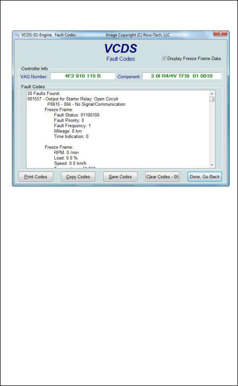
On this screen, VCDS shows you any DTCs (“Diagnostic Trouble Codes” or Fault Codes) present in the control module in which a communications session is currently active. VCDS shows the DTC numbers and also decodes each DTC into meaningful text.
At the top of the screen is shown the VAG Number and Component number as found on the Open Controller screen.
VCDS tells you how many fault codes have been found and displays each of them. The 5,6, or 7-digit number is a standardized VAG fault code, which can be searched in the Factory Repair Manuals. The text is a description of the part and failure mode. The letter and number combination in parentheses is the DIN Component Identifier. This is followed by elaborators describing the condition of the fault such as “004” meaning “No Signal/Communication”. The second line contains the P-code, or generic OBD-II code (if it exists, there are thousands of VAG codes without generic OBD-II equivalents).

Fault Codes cont. - Section 5-B
The Display Freeze Frame Data checkbox adds Freeze Frame data for Fault Codes on control modules using the KWP-2000 / CAN / UDS protocols. Note: Not all control modules fully support this. As a rule of thumb, cars which were re-designed after 2003 will likely have some control modules that support it, and older designs will not. There's no harm in leaving this enabled in any case. However, un-checking it can make the results less cluttered in a scan which contains many fault codes. In vehicles that do not support Freeze Frame, that checkbox will not be present.
One component of Freeze Frame data is the Fault Priority number as described below:
Number |
Meaning |
|
|
0 |
Undefined by the manufacturer. |
|
|
1 |
The fault has a strong influence on drivability, immediate stop is required. |
|
|
2 |
The fault requires an immediate service appointment. |
|
|
3 |
The fault doesn't require an immediate service appointment, but it should be |
|
corrected with the next service appointment. |
|
|
4 |
The fault recommends an action to be taken, otherwise drivability might be |
|
affected. |
|
|
5 |
The fault has no influence on drivability. |
|
|
6 |
The fault has a long term influence on drivability. |
|
|
7 |
The fault has an influence on the comfort functions, but doesn't influence the |
|
car’s drivability. |
|
|
8 |
General Note |
|
|
Fault Frequency shows how many times the conditions that caused the fault have recurred, during all driving cycles. So, if you have a fault with a Frequency of 11, then conditions sufficient to trigger the fault have happened 11 times since the fault was stored. The counter can have values from 0 to 254. It is incremented with each occurrence of the fault (during all driving cycles).
The Reset counter is a number that has been pre-assigned to each fault, with the number of problem-free driving cycles before the fault presumably clears itself. Each time a driving cycle occurs, and the conditions sufficient to trigger the fault do NOT occur, then the reset counter should go down by one. So if you have a fault with a Reset Counter of 40, if the controller goes through a problem-free driving cycle then that number should go down to 39.

Fault Codes cont. - Section 5-C
[Print Codes] will print a Fault Code Report. If your PC is not connected to a printer when this button is pressed, be sure to use Windows to set the printer to "Work Off-Line" first! Later, when you connect the PC to a printer, un-check "Work Off-Line" to print the report.
[Copy Codes] will copy your fault codes to Windows Clipboard. Once you have pressed the Copy Codes button, you may paste the results into the application of your choice, such as MS Word or Notepad.
[Save Codes] will save a plain-text Fault Code Report to the Logs directory of your PC, typically: C:\ross-tech\vcds\Logs\
[Clear Codes - 05] will erase the DTCs from the Control Module's memory. Be aware, this does not fix the problem that caused the fault! DTCs should only be erased after correcting the condition(s) that caused them in the first place. Note: There is no way to erase individual DTCs while leaving others alone. This is not a limitation in VCDS. It's just the way the VAG protocols work.
[Done, Go Back] takes you back to the Controller Information Screen where you can select other functions.

VCDS - Measuring Blocks - Section 6-A
(VAG 1551/1552 function 08)
On this screen, you can read all sorts of data from the Control Module in real-time.
Use [Up] and [Dn] to scroll through the available groups (000 - 255 on most Control Modules) and you can view up to three groups at the same time. Don't become discouraged when you find some that say "ERROR: Group xxx Not Available" or if you find some groups where the fields are all blank. Most 1996 and newer ECU's have Groups in the 200 range, but there are often "gaps" in the numbers.
You can also type a Group number into any or all of the Group boxes and click [Go!]
Dual ECU's: For vehicles with dual ECU's (like the Audi R8), data from both ECU's can be viewed simultaneously by accessing [31-Engine Other] as shown here:

Measuring Blocks cont. - Section 6-B
You can [Log] the data from the measuring blocks. For more information see Data Logging (Section 7 of this manual).
[Switch to Basic Settings] can be used to go to Basic Settings for the Group that is currently being displayed. This should be done only under guidance from the Service Manual or when following some other documented procedure. For more information, see the Basic Settings function (Section 16 of this manual).
Note: Multiple Groups are not permitted in Basic Settings. The [Switch To Basic Settings] button is intentionally disabled if you have groups "running" in the second and third rows. To stop a running group, click on the box that displays the group number (as though you wanted to enter a new number). The button is also disabled on controllers using KWP-2000 / CAN. On those, you need to go directly to the Basic Settings screen.
The data presented in each Measuring Block Group varies greatly from Control Module to Control Module and between different models and years. Some groups are documented in the Factory Repair Manuals, but many are not. Feel free to explore the Control Modules in your car by scrolling through all the Groups. You can't hurt anything with the Measuring Blocks function!
VCDS will attempt to "scale" the raw data coming from the Control Module into realworld units like degrees C, km/h, etc. At the present time, all scaling conversions are to metric units.
Note: Group 000 and any other group that displays 10 fields instead of 4 is an exception. No scaling is possible because the Control Module provides no "Data Type" information for these. Groups of this type can only be displayed in the top row of the screen.
VCDS also tries to elaborate as much as possible what the data means. Unfortunately, the "Data Type" information coming from the Control Module is not that precise. For example: VCDS can tell that a particular field contains a Temperature, but the data from the Controller doesn't tell us whether this is the Coolant Temperature or the Intake Air Temperature.
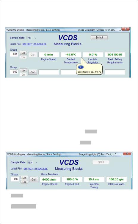
To reduce the confusion, VCDS supports Label Files and will display the name of the Label File on the top left corner of the screen. If you click on the name of the Label File, the file will open in Notepad or whatever program you have set to handle *.LBL files. When a Label file for the Control Module you are looking at does not exist, VCDS will come up with an "educated guess" for what a particular Data Type means. The dealers' VAG-1551 and 1552 scan-tools do not provide any elaboration; they only show what’s in the display fields!
Group 000 supports special Labels. Due to space constraints on the screen, these labels are displayed in a "balloon" when the user clicks on a field:
Measuring Blocks cont. - Section 6-C
Label Files also allow a third label field to be defined for each of the normal measuring block fields. This label is displayed in a balloon when the user clicks on the field. The idea is to put "specified values" in this field:
Sample Rate: Some ECUs may not be willing to produce more than about 3.5 samples per second when running a single group, even with the most aggressive protocol-
timing settings. Other ECUs may be much faster. Except on the slowest most ancient PCs, this is a limitation inherent in the firmware in the ECU, not a limitation in the VCDS software or the PC. Naturally, if two groups are being displayed simultaneously, the sample rate drops about half what it was running a single group, and 3 groups simultaneously runs at around 1/3. Sample Rate will vary from controller to controller. Some controllers (particularly AG4 transmissions and Digifant-III ECU's) use a "hybrid" data-type that requires reading a long header when changing group numbers. Viewing multiple groups still works with these data types, but the sample rate becomes extremely slow. If you see "Reading Header" all the time under the Sample Rate display, you'll know you've got one of these.
In Engine controllers using KWP-2000 or CAN, there is a [Turbo] button in the top right of the Measuring Blocks screen when using a HEX Interface. Pressing this button can significantly speed up sampling, for example over 30 samples per second when logging a single group in our Touareg. Once you have pressed [Turbo] you will remain in this HighSpeed mode until you exit the Measuring Blocks screen:
The [Graph] button is used to open up VC-Scope, a plug-in for VCDS that allows you to graph Measuring Group Information. See Section 34 for information on VC-Scope.
Use [Done, Go Back] to return to the Open Controller screen.

Measuring Blocks cont. - Section 6-D
If you'd like to record just a snapshot in time of the current readings in each group, click on [Add to Log]. This will save the results to your PC, typically in your VCDS\Logs directory
Acceleration Measurement
When you have one or more measuring group with speed (km/h) in it, clicking on [Acceleration] will bring up the Acceleration Measurement window, which allows you to enter start and stop speeds and distances. This is described in the Acceleration Measurement (Section 13 of this manual)..
Advanced Measuring Blocks
You may also want to try the Advanced Measuring Values function (see section 12), which frees you from the grouping format of the Measuring Blocks function.
For controllers using the UDS/ODX/ASAM protocol, the Measuring Blocks function is not available and you MUST use Advanced Measuring Values instead.
Warning! If you wish to observe real-time data while driving the car, please use a second person! Let one drive while the other observes the data, making sure the person holding the PC is not in front of an active airbag!
.
VCDS - Data Logging - Section 7-A
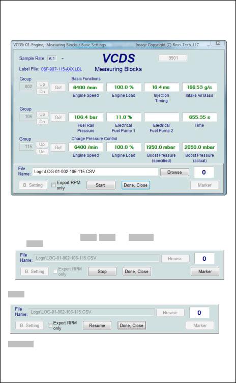
You can log the data from the Measuring Blocks screen to a .CSV file. These files can be opened and analyzed with Excel or other spreadsheet applications.
Export RPM Only when checked will record only RPM from the first field and will not record other fields. Also, this will only record RPM values that are non-zero. This feature can be useful if you are logging to output the file to a spreadsheet or other third party software
While the Log Dialog is open, [Start], [Stop], and [Resume] can all be done with the same button. [Start] begins saving the data to a log file.
[Stop] discontinues the saving of data to a log file
[Resume] continues the saving of data to a log file.
VCDS - Data Logging cont. - Section 7-B
Dual ECU's: For vehicles with dual ECU's (like the Audi R8), data from both ECU's can be logged simultaneously by accessing [31 – Engine Other] as shown here:
The [Marker] function places a sequential number in the file when you click the Marker button. This can be helpful for data analysis.
The [Browse] button allows you to specify the location for your logs. By default, Log Files
will be placed in the Logs sub-folder in your PC, typically: C:\ross-tech\vcds\Logs\
By default, the name of the log file will be the controller number followed by the number for each group number that you are logging. The name can be changed to anything you'd like. If you re-use an existing filename, your new data will be appended to that file.
Switch to Basic Settings is not currently available while logging (but may be added later). However, you can start a log while you're in Basic Settings. If VCDS keeps insisting that it can't open a Log file, you're probably missing the LOGS folder and should re-install VCDS.

VCDS - Data Logging cont. - Section 7-C
Example using Microsoft Excel:
1.Choose the group or groups that you want to view.
2.Click the [Log] button
3.Use default file name if desired. It will append the old file if you use a particular name more than once.
4.Click [Start]
5.Drive the car through the tests that you want to perform
6.Click [Stop]
7.Click [Done] when you're finished logging data.
8.Open Microsoft Excel
9.Click File->Open (change filetype to all *.*)
10.Locate the *.csv file that you created, typically in C:\ross-tech\vcds\Logs\
11.With mouse select the columns you want to graph.
12.Click the Chart Wizard button.
13.Select XY (Scatter) and click one of the formats that has lines.
14.The chart wizard will prompt you to name axes if you want.
15.Pick, for example, RPM values for the x-axis and IAT for the y-axis
You can also use the [Graph] button to open the VC-Scope plug-in for VCDS that allows you to replay LOG files. See Section 34 for information on VC-Scope.
Warning!
If you're going to use VCDS while you're driving, please use a second person! Let one drive while the other observes the data, making sure the person holding the PC is not in front of an active airbag! Obviously, do not break any laws, speeding or otherwise while using VCDS!

VCDS - Single ReadingSection 8-A
(VAG 1551/1552 function 09)
This function allows you to look at real-time data from control modules that support it. However, the data stream coming from the control module gives NO CLUE what the data means or how to scale it into real-world values.
The only way to know what the values mean is to find a reference to this function in the Factory Repair Manual for your car.
This function is rare, but it is used, for example, with some OBD-I 2.8L 12V V6 engines.
The very name of this function annoyed us, so we added a twist. You can look at two channels of "Single Readings" at once!
Use [Up] and [Dn] to scroll through the available groups (000 - 255 on some Control Modules). Don't become discouraged when you find some where the fields are all blank. You can also type a Channel number into the Channel box and click [Go!]
Use [Done, Go Back] to return to the Open Controller screen.
Note: On the Open Controller screen, the Supported Codes button will appear in place of the Single Reading function in modules that support it, since the two functions are mutually exclusive.

VCDS – Supported CodesSection 9-A
Supported Codes function: On the latest control modules which have this capability, VCDS can show all DTC and Failure Mode combinations which a control module is capable of detecting, including the current status of each.
You can sort the results by selecting the radio buttons on the right side of the screen.
Use [OK] to return to the Controller Info / Select Function screen.
Note: On the Open Controller screen, the Supported Codes button will appear in place of the Single Reading function in modules that support it, since the two functions are mutually exclusive.
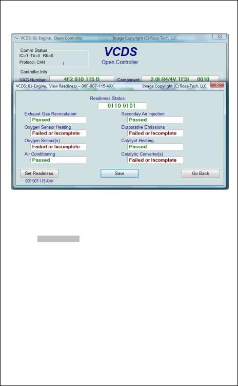
VCDS - View Readiness - Section 10-A
(VAG 1551/1552 function 15)
The Readiness Code is a set of 8 bits, each of which corresponds to one monitored emissions "system" in an OBD-II car. When all readiness bits show "Passed", it means that all systems have been checked and have passed the on-board tests. The Readiness screen shows name of script in title bar and under the [Set Readiness] button, or gives a reason why [Set Readiness] is disabled when that is the case.
Whenever you clear DTCs, all readiness bits that are testable will be set to "Fail" or "Failed or Incomplete". Most cars do not have all 8 systems, so the ECU should recognize the bits corresponding to systems that are not actually in the car. These will come up "Passed" automatically without going through any tests.
It takes a variety of specific driving conditions to "test" all the systems. In practice, driving a properly-functioning car for 2-3 days including at least one short highway trip, should be sufficient to test each of the Readiness Bits to set all of the testable ones to "Passed". It can be done in a short time using a very specific and complicated procedure found in
the On Board Diagnostic section of the Factory Repair Manual for your engine or you can use the Guided Readiness Script function in VCDS as described later in this section.

View Readiness cont. - Section 10-B
VCDS also decodes Readiness bits into meaningful data on modern TDI engines including US-market Common-Rail TDI-140 engines. Diesel Readiness is a VCDS exclusive, not even the VAS-5051/5052 does this:
Click on [Save] to store the results to your PC, typically in this directory on your PC:
C:\Ross-Tech\VCDS\Logs
Use [Go Back] to return to the Open Controller screen.
Notes:
The Readiness function is only available on Engine Controllers that are OBD-II compliant (all 1996 and newer US-Model) or EOBD compliant (all 2001 and newer European-market models).
Non-US models and older TDIs may not support the Readiness function even though they are otherwise OBD-II compliant. OBD-I did not require any "monitors".
12V 2.8L V6 engines may have readiness bits stored in or near Measuring Block Group 029.

View Readiness cont. - Section 10-C
The Guided Readiness Scripts function will guide the user through the process of setting Readiness on those engines which support it by clicking on the [Set Readiness] button. The button will be grayed out if Readiness bits are already set (you can clear fault codes to un-set them) or if appropriate documentation does not exist in VCDS for that specific ECU:
Guided Readiness Scripts require supporting data in Label files. Not every possible engine is currently documented but we hope to have most US-model engines covered in the near future. If you have a specific engine you would like to see covered and have a written procedure for it, please contact us at support@Ross-Tech.com preferably by emailing an AutoScan.
Use [Next] to advance through the on-screen prompts or [Cancel] to exit out of Guided Readiness.

VCDS - Advanced Identification - Section 11-A
(VAS 5051/5052 “Identification Services”)
Corresponds to VAS-5051/5051 "Identification Services"
This function displays additional (and sometimes quite arcane) identifying data from the control module which does not fit on the Open Controller screen.
Notes:
The Advanced ID function is not available on control modules using the old KW1281 protocol.
The amount of data appearing on this screen will vary based on what the control module supports.
[Copy] will copy the information shown on this screen to the Windows Clipboard. Once you have pressed the Copy Codes button, you may paste the results into the application of your choice, such as MS Word or Notepad.
[Save] will save a plain-text report to your PC, typically in this directory: C:\RossTech\VCDS\Logs
Use [Go Back] to return to the Open Controller screen.
 Loading...