


VAG-COM
Diagnostic Software for VW/Audi/SEAT/Skoda
User’s Manual
Version 311.2
See our Website for an Interactive Online version of this manual:


 http://www.ross-tech.com/vag-com/tour/
Copyright (c) 2000-2003 by Ross-Tech, LLC.
888 Sumneytown Pike Lansdale, PA 19446 www.Ross-Tech.com
Disclaimer:
All rights reserved, No part of this publication may be reproduced, stored in a retrieval system, or transmitted in any form or by any means, electronic, mechanical, photocopying, recording, or otherwise, without the prior written permission of Ross-Tech, LLC. The information contained herein is designed only for use with VAG-COM. Ross-Tech, LLC. is not responsible for any use of this information as applied to this or other diagnostic equipment.
Neither Ross-Tech, LLC. nor its affiliates shall be liable to the purchaser of this product or third parties for damages, losses, costs, or expenses incurred by purchaser or third parties as a result of: accident, misuse, or abuse of this product or unauthorized modifications, repairs, or alterations to this product, or failure to comply with Ross-Tech, LLC’s written instructions.
By using VAG-COM, you acknowledge that this Program is provided "as is" and "with all faults, defects and errors" and that all use of the Program is at your own full risk. It has been extensively tested, but we cannot guarantee it will work correctly with every system in every car. We will make our best effort to fix any bugs and to enhance the program, but we specifically disclaim any liability for damage to your computer or your car, and we do not promise to have any particular enhancements available on any specific date.
Copyright © 2003 by Ross-Tech, LLC

VAG-COM
Table of Contents
Getting Started |
2-5 |
|
Main Screen |
6 |
|
Select Control Module |
7 |
|
Open Controller Function Screen |
8-9 |
|
Fault Codes |
10 |
|
Measuring Blocks |
11-12 |
|
Data Logging |
13-14 |
|
Single Reading |
15 |
|
Readiness |
16 |
|
Login |
17 |
|
7-digit PIN/SKC Dialog |
18 |
|
Basic Settings |
19-20 |
|
Output Tests |
21 |
|
Recode |
22 |
|
Adaptation |
23-24 |
|
Security Access |
25 |
|
Auto-Scan |
26-27 |
|
Control Module Finder |
28 |
|
OBD-II |
29-30 |
|
Options |
31-33 |
|
About |
34 |
|
Appendix A: Problems & Issues |
35-37 |
|
Appendix B: FAQ (Frequently Asked Questions) |
38-49 |
|
Appendix C: VAG-Scope |
50-52 |
|
Appendix D: TDI Timing Checker |
53 |
|
Appendix E: VAG Functions |
54 |
1

VAG-COM
Getting Started
VAG-COM allows you to turn a Windows-based PC into a sophisticated diagnostic tool for VW/Audi/SEAT/Skoda models from 1990-2004.


 (Go to our website www.ross-tech.com to download the latest version of VAG-COM. Click on: “Download VAG-COM Software”.)
Connect the Serial or USB end of Interface to the Serial or USB port on your PC. If your PC is further from the vehicle than 6 feet, connect a Serial Extension Cable between the PC and the Interface (USB is not extendable). G
H If you are using a Serial Interface, you can skip to page 4 of this manual. If you are a USB Interface, this message should pop up.
Click on the Found New Hardware message and the Found New Hardware Wizard should start up. Select "Install from a list or specific location (Advanced)" then click [Next >] G
H This dialog should appear. Select "Search for the best driver in these locations" Check "Include this location in the search:"
2

Getting Started cont.
Use the [Browse] button to find the VAG-COM folder (Usually C:\Program Files\VAG-COM\, unless you chose a different folder when you installed the software) Click [OK] G
H Click [Next >] and this dialog should appear, warning you that we haven't paid Microsoft a pound of flesh to certify the driver.
You're going to have to click the [Continue Anyway] button..:-)
When the dialog to the right appears, Click [Finish] : G
Note: If, for some reason, you installed your HEX-USB or TWIN-USB without following the above instructions, and VAG-COM does not work correctly, go into your PC’s Device Manager while the HEX-USB or TWIN-USB is connected. Find the “VAG-COM Compatible USB Interface” and delete it. Then, unplug the HEX-USB or TWIN-USB from your PC, wait 5 seconds and plug it back in. Proceed with the installation starting on Page 2.
3

Getting Started cont.
Connect the car end of your Interface to your vehicle’s
Diagnostic Port. G
H If your vehicle has a 2x2 port (some pre-1996 vehicles), then use a 2x2 Adapter between the Interface and the ports in the car.
Start the VAG-COM program on your PC through either the Start Menu or the icon on your Desktop. G
4

Getting Started cont.
Turn the vehicle’s ignition switch to the ON position. Make sure the key is turned far enough that the dash lights are fully illuminated. The engine may either be running or stopped.
From the Main Screen in VAG-COM (shown on Page 6 of this Manual) click the [Options] button to go into the Options screen (shown on Page 31 of this Manual).
H Select the correct port for your PC’s Serial Port (typically COM1 or COM2) or USB Port (USB) and click the [Test] button. Ensure that VAG-COM finds your interface. You should see a message like this.
•If the Adapter Status is not “Found!”, check the connections at the car and PC. Make sure both are plugged in securely.
•If K1 or K2 status is not “OK”, you may have a short or an open circuit in the car’s diagnostic port (most likely caused by the Aftermarket Radio Problem, as shown in the FAQ in Appendix B of this manual).
Once you have tested successfully, click [OK] and click [Save] to apply this configuration, you will be returned to the Main Screen.
Click on [Select Control Modules] to view the Select Control Module Screen (as shown on page 7 of this manual). Select one of your car's Control Modules such as Engine
After VAG-COM has connected, click on [Fault Codes] to check for Fault Codes (DTC’s). Repeat the process for each of your car's Control Modules. If you encounter problems, see the FAQ in Appendix B of this Manual first. If you still have problems, feel free to contact us with full details about your PC and vehicle, preferably while you are in front of both.
Note: Your car will not have all the Control Modules listed in VAG-COM, only the ones on the Applications Page for your car. See our Website for more info:
www.Ross-Tech.com/vag-com/cars/applications/
5

VAG-COM
Main Screen
This screen appears when you start VAG-COM by clicking the shortcut on your Desktop or by selecting VAG-COM from the Start Menu.
On this screen, you have 7 buttons that you can click with your mouse:
[Select] [Auto-Scan]
[Control Module Finder]
[OBD-II]
[Options]
[About]
[Exit] (This closes the VAG-COM program)
See our Website for an Interactive Online version of this manual:
http://www.ross-tech.com/vag-com/tour/
6

VAG-COM
Select Module Screen
The various computers in the car are called “Control Modules”. On this screen, you select which Control Module you want to "talk" to. Click on the button for “01 - Engine” in order to connect to the engine controller. Note: No single car has all Modules! Newer cars have more, older cars have fewer. Each tab contains groups of modules VAG-COM has buttons for all control module addresses currently supported by the VAS-5051 and VAS-5052 factory diagnostic tools.
H Due to the Airbag Issue in Appendix A,
if you select [15 –Airbags] you will get this warning
Module Tabs
Selecting the Tab for Common, Drivetrain, Chassis, Comfort/Conv., Electronics 1, or Electronics 2 will show you different lists of module buttons.
Direct Entry
You can also enter any address manually. Simply put in the address and click [Go!]
To return to the Main Screen, click [Go Back]
Note: Your car will not have all the Control Modules listed in VAG-COM, only the ones on the Applications Page for your car. See our Website for more info:
www.Ross-Tech.com/vag-com/cars/applications/
7

VAG-COM
Open Controller Function Screen
This screen will appear when VAG-COM is attempting to establish communications with any of the Control Modules shown on the Select Control Modules Screen.
Comm Status = Shows the status of the current communications session. It is normal for VAG-COM to take one or more tries to connect. Once communications have been established:
•IC= Shows the number of times the session has been initialized. If IC increases beyond 1, communications are less than 100% reliable.
•TE= is counters for transmitter errors within individual packets and can indicate unreliable communication.
•RE= is counters for receive errors within individual packets and can indicate unreliable communication.
•Protocol indicates whether the controller speaks KWP-1281 or KWP-2089. (See the Function Chart in Appendix E in this manual for more information).
•A rotating cursor shows that communication is active.
8

Open Controller cont.
Controller Info
Once the communications session has been established, all of the Control Module’s "Identification" data is presented here.
•VAG Number is the VW/Audi part number for this controller. This is often the same number as listed on the sticker on the controller itself.
•Component contains more identification information about the controller and may contain a version number for the controller's internal firmware.
•Soft. Coding is the Software Coding that determines various options for the controller.
•Shop # identifies the WorkShopCode stored in the scan-tool that last Recoded this Control Module. Note: Some older Control Modules are not "codeable" and you may see a Bosch part number or other information in these fields. See the Options screen for information on how VAG-COM deals with WSC.
•The Extra fields can show VIN and Immobilizer information or slave controller part numbers in some vehicles. This text is displayed in VAG-COM in the same manner it is presented by the controller, and may be in German in some controllers.
Basic Functions
This grouping of "Safe" functions are used to read data from the Control Module. Grayed out buttons are functions that have not yet been implemented or are not applicable for this specific controller. Each of these functions is detailed on the following pages.
Advanced Functions
These functions are capable of making various "programming" changes to the Control Module. You should refer to the Factory Repair Manual for your particular car (or to other documented procedures) before "playing" with these functions. It is completely possible to render your vehicle inoperable or damage components if you make changes in this section without the correct information and training. Each of these functions is detailed on the following pages.
Use [Close Controller, Go Back - 06] to properly close the communications session and return to the Select Control Module screen.
9

VAG-COM
Fault Code Screen
On this screen, VAG-COM shows you any DTC's (“Diagnostic Trouble Codes” or Fault Codes). VAG-COM shows
the DTC numbers and also decodes each DTC into meaningful text. G
[Print Codes] will print a Fault Code Report. If your PC is not connected to a printer when this button is pressed, be sure to use Windows to set the printer to "Work Off-Line" first! Later, when you connect the PC to a printer, un-check "Work Off-Line" to print the report.
[Copy Codes] will copy your fault codes to Windows Clipboard. Once you have pressed the Copy Codes button, you may paste the results into the application of your choice, such as
MS Word or Notepad.
H [Freeze Frame] adds Freeze Frame data for Fault Codes on control modules using the KWP-2000 protocols. Note: Not all control modules fully support this; very few cars can currently handle freezeframe data using the VAG proprietary protocols. Self-explanatory messages will appear in place of data when this function is not supported.
[Clear Codes - 05] will erase the DTC's from the Control Module's memory. Be aware, this is does not fix the problem that caused the fault! DTC's should only be erased after correcting the condition(s) that caused them in the first place. Note: There is no way to erase individual DTC's while leaving others alone. This is not a limitation in VAG-COM it's just the way the VAG protocols work.
[Go Back] takes you back to the main Control Module screen where you can select other functions.
10
VAG-COM
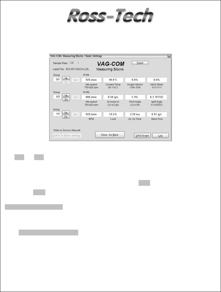
Measuring Blocks
(VAG 1551/1552 function 08)
On this screen, you can read all sorts of data from the Control Module in real-time.
Use [Up] and [Dn] to scroll through the available groups (000 - 255 on most Control Modules). Don't become discouraged when you find some that say "ERROR: Group xxx Not Available" or if you find some groups where the fields are all blank. Most 1996 and newer ECU's have Groups in the 200 range, but there are often "gaps" in the numbers.
You can also type a Group number into the Group box and click [Go!]
You can also [Log] the data from the measuring blocks. For more information see page 13 – Data Logging.
[Switch to Basic Settings] can be used to go to Basic Settings for the Group that is currently being displayed. This should be done only under guidance from the Service Manual or when following some other documented procedure. For more information see page 19 – Basic Settings.
NOTE: Multiple Groups are not permitted in Basic Settings. The
[Switch To Basic Settings] button is intentionally disabled if you have groups "running" in the second and third rows. To stop a running group, click on the box that displays the group number (as though you wanted to enter a new number). This button is also disabled on controllers using KWP-2000. On those, you need to go directly to the Basic Settings screen.
The data presented in each Measuring Block Group varies greatly from Control Module to Control Module and between different models and years. Some groups are documented in the Factory Repair Manuals, but many are not. Feel free to explore the Control Modules in your car by scrolling through all the Groups. You can't hurt anything with the Measuring Blocks function!
11

Measuring Blocks cont.
In each case, VAG-COM will attempt to "scale" the raw data coming from the Control Module into real-world units like degrees C, km/h, etc. At the present time, all scaling conversions are to metric units.
Note: Group 000 and any other group that displays 10 fields instead of 4 is an exception. No scaling is possible because the Control Module provides no "Data Type" information with the data for these. Groups of this type can only be displayed in the top row of the screen.
VAG-COM also tries to elaborate as much as possible what the data means. Unfortunately, the "Data Type" information coming from the Control Module is not that precise. For example: VAG-COM can tell that a particular field contains a Temperature, but the data from the Controller doesn't tell us whether this is the Coolant Temperature or the Intake Air Temperature.
To reduce the confusion, VAG-COM supports Label Files and will display the name of the Label File. When a Label file for the Control Module you are looking at does not exist, VAG-COM will come up with an "educated guess" for what a particular Data Type means. The dealers' VAG-1551 and 1552 scan-tools do not provide any elaboration; they only show what’s in the display fields!
Sample Rate: We can get just over 4.0 samples per second from our '97 VR6 ECU (single group) with the most aggressive protocol-timing settings. This ECU runs at 9600 baud. Most newer ECU's run at 10400 and should give proportionately more. Naturally, if two groups are being
displayed simultaneously, the sample rate drops to around 2.0, and 3 groups simultaneously runs at around 1.3. Sample Rate will vary from controller to controller and the PC used will also have some effect. Some controllers (particularly AG4 transmissions and Digifant-III ECU's) use a "hybrid" datatype that requires reading a long header when changing group numbers. Viewing multiple groups still works with these data types, but the sample rate becomes extremely slow. If you see "Reading Header" all the time under the Sample Rate display, you'll know you've got one of these.
In Engine controllers using KWP-2000, there is a [Turbo] button in Measuring Blocks screen of the latest version of VAG-COM. Pressing this button can significantly speed up sampling, in some cases to over 30 samples per second when logging a single group. Once you have pressed [Turbo] you will remain in this High-Speed mode until you exit the Measuring Blocks screen.
[VAG-Scope] is a plug-in for VAG-COM that allows you to graph Measuring Group Information. See Appendix C for information on VAG-Scope.
Use [Done, Go Back] to return to the Controller Info / Select Function screen.
Warning!
If you wish to observe real-time data while driving the car, use a second person who is not in front of an active airbag!
12

VAG-COM
Data Logging
You can log the data from the Measuring Blocks screen to a .CSV file. These files can be opened and analyzed with Excel or other spreadsheet applications.
While the Log Dialog is open;
[Start], [Stop], and [Resume] can all be done with the same button. [Start] begins saving the data to a log file.
[Stop] discontinues the saving of data to a log file
[Resume] continues the saving of data to a log file.
The [Marker] function places a sequential number in the file when you click the Marker button. This can be helpful for data analysis.
The [Browse] button is not currently implemented. All Log Files will be placed in the LOGS subfolder in your PC’s VAG-COM directory.
By default, the name of the log file will be the controller number followed by the number for
each group number that you are logging. The name can be changed to anything you'd like. If you reuse an existing filename, your new data will be appended to that file.
13

Data Logging cont.
Switch to Basic Settings is not currently available while logging (but may be added later). However, you can start a log while you're in Basic Settings. If VAG-COM keeps insisting that it can't open a Log file, you're probably missing the LOGS folder.
Example using Microsoft Excel:
1.Choose the Measuring Block Group that you want to view.
2.Click [LOG] button
3.Use default file name if desired. It will append the old file if you use a particular name more than once.
4.Click [DONE] when you're finished logging data.
5.Open Microsoft Excel
6.Click File->Open (change filetype to all *.*) and select the log file that you made.
7.With mouse select the columns you want to graph.
8.Click the Chart Wizard button.
9.Select XY (Scatter) and click one of the formats that has lines.
10.The chart wizard will prompt you to name axes if you want.
You can also use the [VAG-Scope] plug-in for VAG-COM that allows you to replay LOG files. See Appendix C for information on VAG-Scope.
Warning!
If you're going to use VAG-COM while you're driving, please use a second person! Let one drive while the other observes the data, making sure the person holding the PC is not in front of an active airbag! Obviously, do not break any laws, speeding or otherwise while using VAG-COM!
14

VAG-COM
Single Reading
(VAG 1551/1552 function 15)
This function allows you to look at real-time data from control modules that support it. However, the data stream coming from the control module gives NO CLUE what the data means or how to scale it into real-world values.
The only way to know what the values mean is to find a reference to this function in the Factory Repair Manual for your car.
This function is rare, but it is used, for example, with some OBD-I 2.8L 12V V6 engines.
The very name of this function annoyed us, so we added a twist. You can look at two channels of "Single Readings" at once!
Use [Done, Go Back] to return to the Controller Info / Select Function screen.
15

VAG-COM
View Readiness
(VAG 1551/1552 function 15)
The Readiness Code is a set of 8 bits, each of which corresponds to one monitored emissions "system" in an OBD-II car. When all readiness bits show "pass", it means that all systems have been checked and pass the on-board tests. Whenever you clear DTC's or remove power from the ECU, all readiness bits will be set to "fail". Most cars do not have all 8 systems, so as soon as you apply power again, the bits corresponding to systems that are not actually in the car will come up "pass" again.
The above screen-shot was taken immediately after clearing the DTC's in a 1997 VR6. You can see that this car does not support "monitors" for the EGR, Catalyst Heating, or Air Conditioning because this specific car does not have EGR or Catalyst Heating. It does have Air Conditioning, but a "monitor" is only required if the system uses ozone-depleting refrigerant (R12).
It takes a variety of specific driving conditions to "test" all the systems. It can be done in a short time using a very specific and complicated procedure found in the On Board Diagnostic section of the Factory Repair Manual for your engine. The alternative is just to drive the car for 2-3 days. Make sure you include at least one short highway trip and your Readiness Bits should all read "Pass" again.
Use [Go Back] to return to the Controller Info / Select Function screen.
Note: This function is only available on Engine Controllers that are OBD-II compliant (all 1996 and newer US-Model gasoline engines). Non-US models and TDI's may not support this function even though they are otherwise OBD-II compliant. OBD-I did not require any "monitors". 12V 2.8L V6 engines may have readiness bits stored in or near Measuring Block Group 029.
16
 Loading...