


SmartPower™ Solutions
Quick Start Guide
00825-0100-4701, Rev DD
April 2021

Quick Start Guide April 2021
Safety Messages
NOTICE
This guide provides basic guidelines for the SmartPower family of products. It does not provide
instructions for detailed configuration, diagnostics, maintenance, service, troubleshooting, or
installation of wireless devices. Refer to the wireless device's manuals and Quick Start Guides (QSG) for
more instruction. This guide is also available electronically on Emerson.com/Rosemount.
WARNING
Explosions could result in death or serious injury.
Installation of this power module in an explosive environment must be in accordance with the
appropriate local, national, and international standards, codes, and practices. Review the Product
Certifications section for any restrictions associated with a safe installation.
• Before connecting a handheld communicator in an explosive atmosphere, ensure the instruments
are installed in accordance with intrinsically safe or non-incendive field wiring practices.
Electrical shock could cause death or serious injury.
• Avoid contact with the leads and terminals. High voltage that may be present on leads can cause
electrical shock.
• The power module may be replaced in a hazardous area. The power module has surface resistivity
greater than one gigaohm and must be properly installed in the wireless device enclosure. Care
must be taken during transportation to and from the point of installation to prevent electrostatic
charge build-up.
CAUTION
Each Black Power Module contains two “C” size primary lithium-thionyl chloride battery. Primary
lithium batteries are regulated in transportation by the U. S. Department of Transportation, and are
also covered by IATA (International Air Transport Association), ICAO (International Civil Aviation
Organization), and ARD (European Ground Transportation of Dangerous Goods). It is the responsibility
of the shipper to ensure compliance with these or any other local requirements. Consult current
regulations and requirements before shipping.
Contents
Warning on product labels........................................................................................................... 3
Physical installation...................................................................................................................... 4
Verify operation........................................................................................................................... 6
Disposal/recycling of depleted power modules............................................................................ 9
Product Certifications.................................................................................................................10
2 Emerson.com/Rosemount

April 2021 Quick Start Guide
1 Warning on product labels
The Rosemount 701P power modules each have a warning printed on them.
In each case the warning text is the same. Below is a figure that shows each
label.
The text of the warning is: “WARNING Potential Static Hazard, Use Caution
when Handling. Risk of Fire, Explosion or Severe Burn Hazard. DO NOT
Recharge, Disassemble, Heat above 100 °C, Incinerate or Expose Contents to
Water. Li metal content approx 5g.”
Figure 1-1: Warning Label on 701PBK
Figure 1-2: Warning Label on 701PGN
Quick Start Guide 3

Quick Start Guide April 2021
2 Physical installation
There are two types of power modules that will be discussed in this
document. They are the black power module (701PBK) and the green power
module (701PGN).
2.1 Installing Black power module (701PBK)
Prerequisites
Install the HART® device according to standard installation practices and the
manufacturer’s instructions, being sure to use an approved thread sealant
on all connections.
Procedure
1. Unscrew the power module cover from the wireless device.
2. Connect the power module to the wireless device. The power
module has a keyed connection to prevent improper connection.
Note
Wireless devices should be powered up in order of proximity from
the Smart Wireless Gateway, beginning with the closest device to the
Gateway. This will result in a simpler and faster network installation.
3. Connect the power module to the wireless device. The power
module has a keyed connection to prevent improper connection.
Figure 2-1: Black Power Module Installation
2.2
4 Emerson.com/Rosemount
Installing Green power module (701PGN)
Prerequisites
Install the HART device according to standard installation practices and the
manufacturer’s instructions, being sure to use an approved thread sealant
on all connections.

April 2021 Quick Start Guide
Procedure
1. Unscrew the power module cover from the wireless device.
2. Connect the green power module to the wireless device. The green
power module has a keyed connection to prevent improper
connection. If the Green power module is placed into the housing the
wrong way, it will not fit entirely into the housing.
Note
Wireless devices should be powered up in order of proximity from
the Smart Wireless Gateway, beginning with the closest device to the
Gateway. This will result in a simpler and faster network installation.
3. Close the housing cover and tighten. Ensure the power module cover
is fully tightened to prevent moisture ingress. The lip of the polymer
power module cover should be in contact with the surface of the
polymer enclosure to ensure a proper seal. Do not over tighten.
Figure 2-2: Green Power Module Installation
Quick Start Guide 5

$
&
%
1 2 3
4 5 6
7 809
Quick Start Guide April 2021
3 Verify operation
Operation can be verified in four locations: by using the Field
Communicator, at the Gateway via the Wireless Gateway’s integrated web
server, via AMS Wireless Configurator, or with the wireless device’s LCD
display.
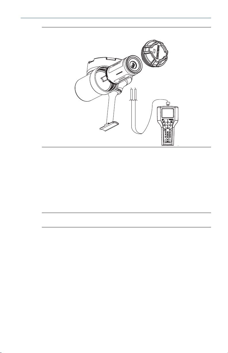
3.1 Verify operation using Field Communicator
If you are able to communicate to the wireless device via a Field
Communicator, the power module is powering the device and working
correctly. Figure 5 shows how to connect a Field Communicator to a wireless
device with either the black or green power module.
Figure 3-1: Connect to Device
A. Communication terminals
B. Handheld communicator
C. HART modem
6 Emerson.com/Rosemount
April 2021 Quick Start Guide
Figure 3-2: Field Communicator
3.2 Verify operation using Emerson Wireless Gateway
If the wireless device was configured with the Network ID and Join Key, and
sufficient time has passed for network polling, the transmitter will be
connected to the network. To verify device operation and connection to the
network with the Smart Wireless Gateway’s integrated web server, open the
Smart Wireless Gateway’s integral web interface and navigate to the
Explorer page. If the wireless device has joined the network, the power
module is functioning properly.
Note
It may take several minutes for the device to join the network.
3.3
Quick Start Guide 7
Verify operation using AMS Device Manager
When the device has joined the network, it will appear in the AMS Device
Manager as illustrated below.

Quick Start Guide April 2021
Figure 3-3: AMS Device Manger
3.4 Verify operation using wireless device LCD Display
If the wireless device that you are connecting the power module to has an
LCD display, it can be used to verify operation. When the power module is
first connected to the wireless device, the LCD display will turn on for
approximately 40 seconds. If the LCD display turns on after the power
module is installed, the power module is functioning properly.
3.5 Troubleshooting
If the wireless device does not turn on after the power module is installed,
the power module may be depleted. Change out the power module and see
if the wireless device turns on. If not, refer to the troubleshooting section of
the wireless device's manual.
8 Emerson.com/Rosemount

April 2021 Quick Start Guide
4 Disposal/recycling of depleted power modules
1. Dispose in accordance with applicable laws and regulations in your
country and state.
2. Disposal should only be performed by authorized professionals in
accordance with applicable requirements for hazardous waste
transportation and disposal.
3. Incineration should only be performed by trained professionals in
authorized facilities.
Shipping regulations
Primary lithium batteries are regulated in transportation by the U.S.
Department of Transportation, and are also covered by IATA (International
Air Transport Association), ICAO (International Civil Aviation Organization),
and ARD (European Ground Transportation of Dangerous Goods). It is the
responsibility of the shipper to ensure compliance with these or any other
local requirements. Please consult current regulations and requirements
before shipping.
Handling considerations
Each black power module contains two “C” size primary lithium batteries.
Each green power module contains one “D” size primary lithium battery.
Under normal conditions, the battery materials are self-contained and are
not reactive as long as the batteries and the battery pack integrity are
maintained. Care should be taken to prevent thermal, electrical, or
mechanical damage. Contacts should be protected to prevent premature
discharge.
Use caution when handling the power module. It may be damaged if
dropped onto a hard surface. Battery hazards remain when cells are
discharged.
Environmental considerations
As with any battery, local environmental rules and regulations should be
consulted for proper management of spent batteries. If no specific
requirements exist, recycling through a qualified recycler is encouraged.
Consult the materials safety data sheet for battery specific information.
Quick Start Guide 9

Quick Start Guide April 2021
5 Product Certifications
Rev 4.0
5.1 European Directive information
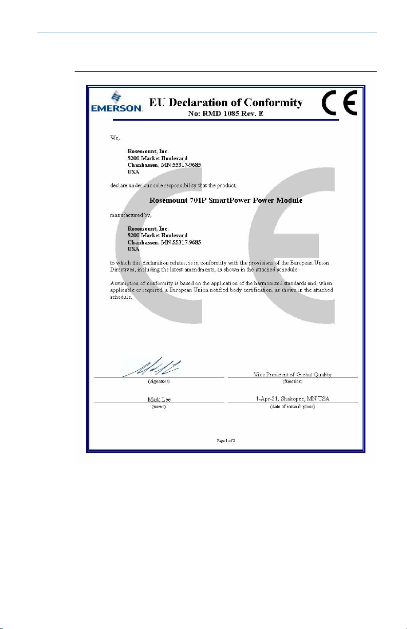
A copy of the EU Declaration of Conformity can be found at the end of this
guide The most recent revision of the EU Declaration of Conformity can be
found at Emerson.com/Rosemount.
5.2 Ordinary location certification
As standard, the transmitter has been examined and tested to determine
that the design meets the basic electrical, mechanical, and fire protection
requirements by FM Approvals, a nationally recognized test laboratory
(NRTL) as accredited by the Federal Occupational Safety and Health
Administration (OSHA).
5.3 North America
The US National Electrical Code® (NEC) and the Canadian Electrical Code
(CEC) permit the use of Division marked equipment in Zones and Zone
marked equipment in Divisions. The markings must be suitable for the area
classification, gas, and temperature class. This information is clearly defined
in the respective codes.
5.4 USA
5.4.1 KF FM Intrinsically Safe (IS)
Certificate:
Standards:
Markings:
Special Condition for Safe Use (X):
Replacement of power module, see instructions for final product.
5.5
Canada
5.5.1 KF CSA Intrinsically Safe
Certificates:
Standards:
10 Emerson.com/Rosemount
3042016
FM Class 3600 – 1998, FM Class 3610 – 2010, FM Class 3810
– 2005
IS CL I, DIV 1, GP A, B, C, D; CL II, DIV 1, GP E, F, G; Class III;
Class 1, Zone 0 AEx ia IIC T4; T4(-40 °C ≤ Ta ≤ +70 °C)
(See Table 5-1 or Table 5-2 for parameters)
2430393
CAN/CSA C22.2 No. 0-M91, CSA Std C22.2 No. 157-92
April 2021 Quick Start Guide
Markings
Special Condition for Safe Use (X):
The power modules are certified as components for use in intrinsically safe
products where the suitability/combination of use in the final assembly shall
be subjected to CSA acceptance. The final assembly must incorporate all
protection features necessary for batteries in accordance with applicable
standards of the final intrinsically safe application.
Intrinsically Safe Class I, Division 1, Groups A, B, C, and D
T3C(Ta ≤ +70 °C) Warning – refer to QIG 825-0100-4701 for
Safe I.S. Use
(See Table 5-1 or Table 5-2 for parameters)
5.6 Europe
5.6.1 KF ATEX Intrinsic Safety
Certificate:
Standards:
Markings
Special Condition for Safe Use (X):
The plastic enclosure of the Model 701P SmartPower Power Modules may
constitute a potential electrostatic ignition risk and caution should be used
when being handled.
Baseefa11ATEX0042X
EN 60079-0: 2012+A11:2013, EN 60079-11: 2012
II 1 G Ex ia IIC T4 Ga, T4(-55 °C ≤ Ta ≤ +70 °C)
II 1 G Ex ia IIC T5 Ga, T5(-55 °C ≤ Ta ≤ +40 °C)
(See Table 5-1 or Table 5-2 for parameters)
Note
This condition of use does not apply after a Power Module is installed within
a wireless transmitter enclosure.
5.7
International
5.7.1 KF IECEx Intrinsic Safety
Certificate:
Standards:
Markings:
Quick Start Guide 11
IECEx BAS 11.0026X
IEC 60079-0: 2011, IEC 60079-11: 2011
Ex ia IIC T4/T5 Ga, T4(-55 °C ≤ Ta ≤ +70 °C), T5(-55 °C ≤ Ta ≤
+40 °C)

Quick Start Guide April 2021
Special Condition for Safe Use (X):
The plastic enclosure of the Model 701P SmartPower Power Modules may
constitute a potential electrostatic ignition risk and caution should be used
when being handled.
Note
This condition of use does not apply after a Power Module is installed within
a wireless transmitter enclosure.
5.8 EAC - Belarus, Kazakhstan, Russia
5.8.1 KF Technical Regulation Custom Union (EAC) Instrinsic Safety
Certificate:
Markings:
Table 1: 701PBK
Table 2: 701PGN
TC RU C-US.MIO62.B.04747
0Ex ia IIC T4/T5 Ga X
T4 (-55 °C ≤ Ta ≤ +70 °C)
T5 (-55 °C ≤ Ta ≤ +40 °C)
5.9 INMETRO - Brazil
5.9.1 KF INMETEO Intrinsic Safety
Certificate:
Standards
Markings:
UL-BR 14.0123X
ABNT NBR IEC 60079-0:2008 + Errata 1:2011, ABNT NBR IEC
60079-11:2009
Ex ia IIC T4/T5 Ga X
T4 (-55 °C ≤ Ta ≤ +70 °C)
T5 (-55 °C ≤ Ta ≤ +40 °C)
5.10 China
5.10.1 KF NEPSI 本质安全
证书
所用标准
标志
GYJ20.1357X(CCC 认证)
GB3836.1 – 2010, GB3836.4 – 2010, GB3836.20-2010
Ex ia IIC T4/T5 Ga
特殊使用条件(X):
电池外壳为非金属材质,可能产生静电危险,只能用湿布擦拭。
12 Emerson.com/Rosemount

April 2021 Quick Start Guide
使用注意事项:
1. 电池外壳为非金属材质,可能产生静电危险,只能用湿布擦拭。使
用注意事项:1. 产品使用环境温度为:温度组别产品使用环境温度
温度组别 产品使用环境温度
T4 -60 °C ≤ Ta ≤ +70 °C
T5 -60 °C ≤ Ta ≤ +40 °C
2. 本安电气参数:
5.11
电池类型 最高输出
电压 Uo
(V)
BK 7.8 2.16 0.83 3.0 9.4
GN 3.9 2.78 2.71 100 4.6
最大输出
电流 Io (A)
最大输出
功率 Po
(W)
最大外部等效参数
Co(μF) Lo(μH)
3. 用户不得自行更换该产品的零部件,应会同产品制造商共同解决运
行中出现的故障,以杜绝损坏现象的发生。
4. 产品的安装、使用和维护应同时遵守产品使用说明书、
GB3836.13-2013“爆炸性环境 第 13 部分:设备的修理、检修、修
复和改造”、GB/T3836.15-2017“爆炸性环境 第 15 部分:电气装置
的设计、选型和安装”、GB/T3836.16-2017“爆炸性环境 第 16 部
分:电气装置的检查与维护”、GB/T 3836.18-2017“爆炸性环境 第
18 部分:本质安全电气系统”、GB50257-2014“电气装置安装工程
爆炸和火灾危险环境电力装置施工及验收规范”的有关规定。
See Table 5-1 or Table 5-2 for parameters.
Tables
Table 5-1: 701PBK
U
o
I
o
P
o
C
o
L
o
7.8 V
2.16 A
0.83 W
3.0 µF
7.6 µH
Table 5-2: 701PGN
U
o
I
o
Quick Start Guide 13
3.9 V
2.78 A

Quick Start Guide April 2021
Table 5-2: 701PGN (continued)
P
o
C
o
L
o
2.71 W
100 µF
4.6 µH
14 Emerson.com/Rosemount
April 2021 Quick Start Guide
5.12 Declaration of Conformity
Quick Start Guide 15
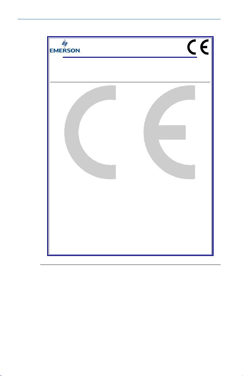
EU Declaration of Conformity
No: RMD 1085 Rev. E
Page 2 of 2
EMC Directive (2014/30/EU)
Harmonized Standards:
EN 61326-1: 2013
ATEX Directive (2014/34/EU)
Baseefa11ATEX0042X – Intrinsic Safety Certificate
Equipment Group II, Category 1 G
Ex ia IIC Ga T4/T5
Harmonized Standards:
EN 60079-0:2012/A11:2013
EN 60079-11: 2012
ATEX Notified Body
SGS FIMKO OY [Notified Body Number: 0598]
Takomotie 8
00380 HELSINKI
Finland
ATEX Notified Body for Quality Assurance
SGS FIMKO OY [Notified Body Number: 0598]
Takomotie 8
00380 HELSINKI
Finland
Quick Start Guide April 2021
16 Emerson.com/Rosemount
ᴹ
China RoHS
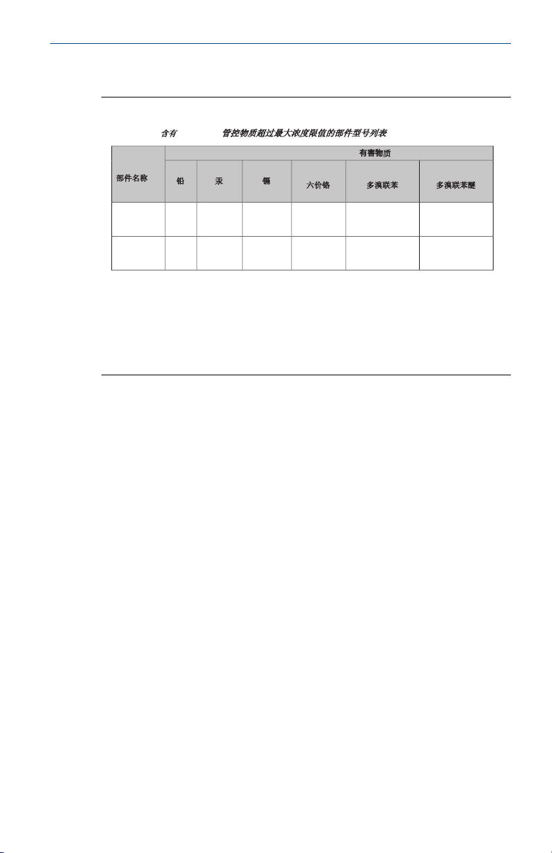
㇑᧗⢙䍘䎵䗷ᴰབྷ⎃ᓖ䲀٬Ⲵ䜘Ԧරࡇ㺘
List of Parts with China RoHS Concentration above MCVs
Part Name
䜘Ԧ〠
Hazardous Substances / 有害物峐
Lead
䫵
(Pb)
Mercury
⊎
(Hg)
Cadmium
䭹
(Cd)
Hexavalent
Chromium
ޝԧ䬜
(Cr +6)
Polybrominated
biphenyls
ཊⓤ㚄㤟
(PBB)
Polybrominated
diphenyl ethers
ཊⓤ㚄㤟䟊
(PBDE)
⭥ᆀ㓴Ԧ
Electronics
Assembly
X O O O O
O
⭥⊐㓴Ԧ
Battery
Assembly
X O O O O
O
ᵜ㺘Ṭ㌫ᦞ
SJ/T11364
Ⲵ㿴ᇊ㘼ࡦ
This table is proposed in accordance with the provision of SJ/T11364.
O:
Ѫ䈕䜘ԦⲴᡰᴹ൷䍘ᶀᯉѝ䈕ᴹᇣ⢙䍘Ⲵ䟿൷վҾ
GB/T 26572
ᡰ㿴ᇊⲴ䲀䟿㾱≲
O: Indicate that said hazardous substance in all of the homogeneous materials for this part is below the limit requirement of
GB/T 26572.
X:
Ѫ൘䈕䜘Ԧᡰ֯⭘Ⲵᡰᴹ൷䍘ᶀᯉ䟼ˈ㠣ቁᴹа㊫൷䍘ᶀᯉѝ䈕ᴹᇣ⢙䍘Ⲵ䟿儈Ҿ
GB/T 26572
ᡰ㿴ᇊⲴ䲀䟿㾱≲
X: Indicate that said hazardous substance contained in at least one of the homogeneous materials used for this part is above
the limit requirement of GB/T 26572.
Rosemount 701P
Rosemount 701P
April 2021 Quick Start Guide
5.13 China RoHS
Quick Start Guide 17

Quick Start Guide April 2021
18 Emerson.com/Rosemount

April 2021 Quick Start Guide
Quick Start Guide 19

*00825-0100-4701*
00825-0100-4701, Rev. DD
Quick Start Guide
April 2021
For more information:
©
2021 Emerson. All rights reserved.
Emerson Terms and Conditions of Sale are
available upon request. The Emerson logo
is a trademark and service mark of
Emerson Electric Co. Rosemount is a mark
of one of the Emerson family of
companies. All other marks are the
property of their respective owners.
www.emerson.com
 Loading...