

Page 1

Quick Start Guide
00825-0100-4145, Rev CA
February 2021
Rosemount™ Smart Pressure Gauge
Page 2

Quick Start Guide February 2021
This guide provides basic guidelines for Rosemount Smart Pressure Gauges. It does not provide
instructions for configuration, diagnostics, maintenance, service, troubleshooting, or intrinsically safe
(I.S.) installations. Refer to the Rosemount Smart Pressure Gauge Reference Manual for more
instruction. The manual and this guide are also available electronically.
NOTICE
Shipping considerations
The device is shipped with the battery installed.
Each device contains one “D” size primary lithium-thionyl chloride battery. Primary lithium
batteries are regulated in transportation by the U.S. Department of Transportation, and are also
covered by IATA (International Air Transport Association), ICAO (International Civil Aviation
Organization), and ARD (European Ground Transportation of Dangerous Goods). It is the
responsibility of the shipper to ensure compliance with these or any other local requirements.
Consult current regulations and requirements before shipping.
WARNING
Explosions could result in death or serious injury.
Installation of device in an explosive environment must be in accordance with appropriate local,
national, and international standards, codes, and practices.
Ensure device is installed in accordance with intrinsically safe or non-incendive field practices.
Electrical shock could cause death or serious injury.
Device must be installed to ensure a minimum antenna separation distance of 8 in. (20 cm) from
all persons.
Care must be taken during transportation of device to prevent electrostatic charge build-up.
Process leaks could result in death or serious injury.
Handle the device carefully.
Failure to follow these installation guidelines could result in death or serious injury.
Ensure only qualified personnel perform the installation.
Contents
Required equipment.................................................................................................................... 3
What’s in the box......................................................................................................................... 4
Optional: Power/device check...................................................................................................... 6
Optional: Normal range indication option.................................................................................... 7
Installation procedure.................................................................................................................. 8
Troubleshooting........................................................................................................................ 12
Product certifications................................................................................................................. 13
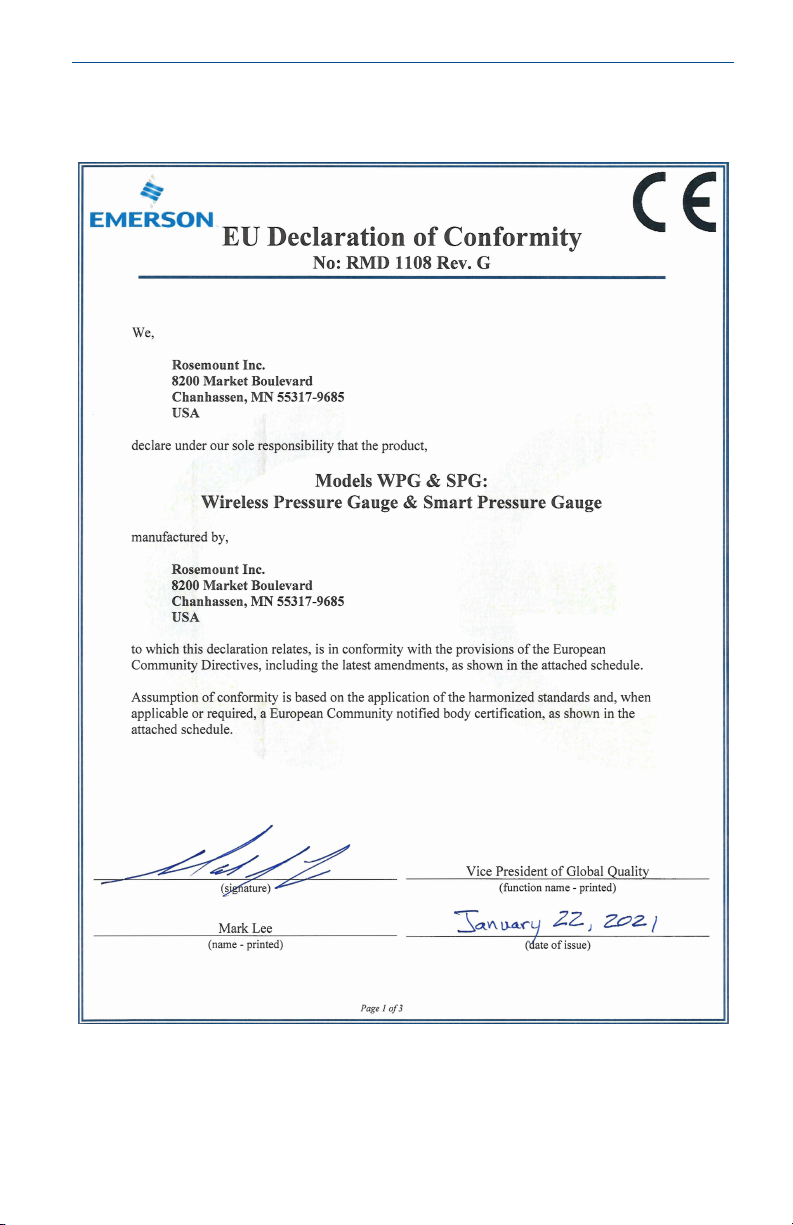
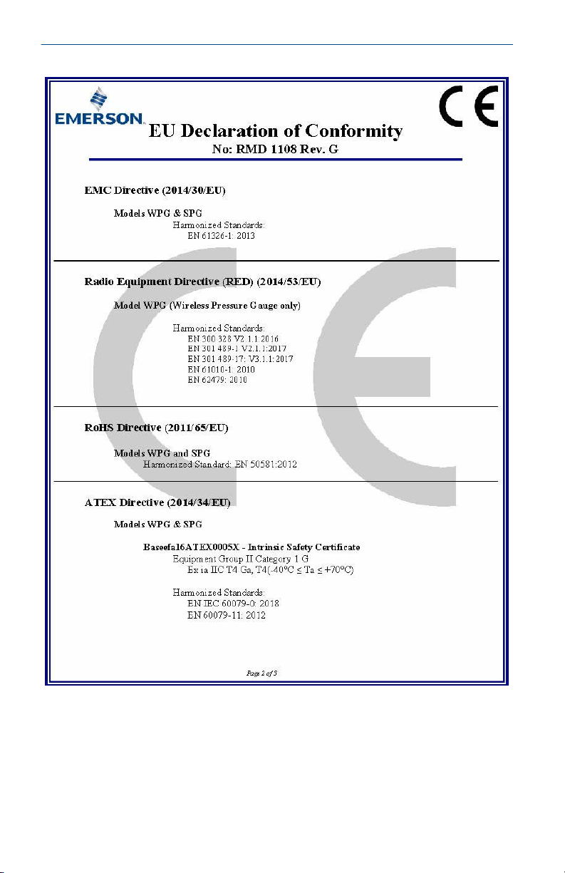
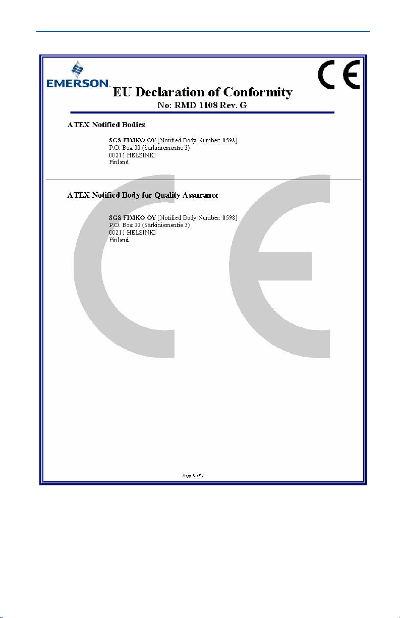
Declaration of conformity.......................................................................................................... 17
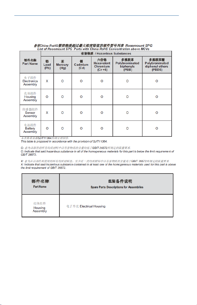
China RoHS................................................................................................................................ 20
2 Emerson.com/Rosemount
Page 3

February 2021 Quick Start Guide
1 Required equipment
Figure 1-1: Anti-seize paste or PTFE tape (for NPT threaded connection)
Figure 1-2: Standard tools (e.g., screwdriver, wrench, pliers)
Quick Start Guide 3
Page 4

Quick Start Guide February 2021
2 What’s in the box
Smart Pressure Gauge Quick Start Guide
The following options are also available and will ship with the Rosemount
Smart Pressure Gauge if ordered.
Rosemount 306 Integral Manifold
(model code S5)
4 Emerson.com/Rosemount
B4 bracket (model code B4)
Page 5

February 2021 Quick Start Guide
Rosemount 1199 Seal(model code S1) Product Certification
Q4: Calibration Cert
QG: Calibration Cert and GOST
Verification Cert
QP: Calibration Cert and Tamper
Evident Seal
Q8: Material Traceability cert per EN
102043.1
Q15: Cert of Compliance to NACE
MR0175/ISO 15156 for wetted materials
Q25: Cert of Compliance to NACE
MR00103 for wetted materials
Normal range Indication (model code LK) Product Certification model codes
Quick Start Guide 5
Page 6

Quick Start Guide February 2021
3 Optional: Power/device check
The device is designed to be installation-ready.
Procedure
1. To check device battery prior to installation, perform Turn on device
2. Slide the ON/OFF switch to the OFF position until ready for use.
6 Emerson.com/Rosemount
Page 7

February 2021 Quick Start Guide
4 Optional: Normal range indication option
Important
• The stickers are intended to be installed on the dial only and should not
be applied on the inside or outside of the housing cover.
• Stickers should be applied in an environment where the ambient
temperature is above 50 °F (10 °C)
Procedure
1. Modify each of the stickers to desired size.
2. Remove housing cover.
3. Slide ON/OFF switch to the OFF position and wait for the LED to stop
flashing.
4. Gently move the needle in the clockwise direction until it is pointing
at the red X.
NOTICE
Equipment Damage
Use caution as the electronics assembly is connected to the needle.
5. Remove any debris on the dial, so it does not become trapped under
the sticker.
6. Peel back the white paper backing of the sticker.
7. Slowly lower the sticker onto the surface of the dial in the desired
location and rub it in place firmly. Repeat steps Step 6 and Step 7
until desired indication locations are set.
Moving the sticker after initial contact is not recommended as this
decreases the amount of adhesive on the back of the sticker.
8. Slide ON/OFF switch to the ON position.
9. Replace housing cover.
Quick Start Guide 7
Page 8

OR
Quick Start Guide February 2021
5 Installation procedure
Procedure
1. Seal and protect threads
2. Mount device
Note
Use wrench on flats, not on housing.
5.1
Mounting orientation
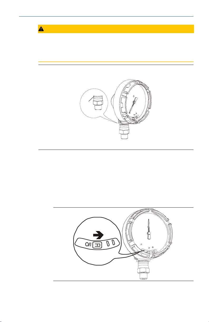
The low side pressure port (atmospheric reference) is located in the neck of
the device behind the housing.
The vent path is between the housing and sensor.
8 Emerson.com/Rosemount
Page 9
A
February 2021 Quick Start Guide
CAUTION
Keep the vent path free of any obstruction, including but not limited to
paint, dust, and lubrication by mounting the device so the process can drain
away.
Figure 5-1: Low Side Pressure Port
A. Low side pressure port (atmospheric reference)
5.2 Turn on device
Check to ensure the device and battery are working properly.
Procedure
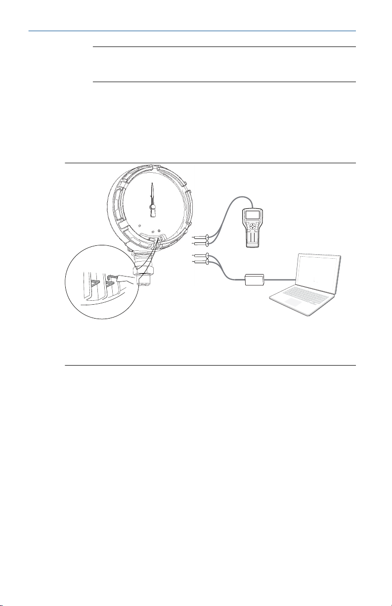
1. Twist the cover counterclockwise to remove it.
2. Slide the OFF/ON switch to the ON position to initiate the power
sequence.
Quick Start Guide 9
Page 10
1 2 3
64 5
8 709
A
B
C
Quick Start Guide February 2021
Note
During the power sequence, the dial tests full range of motion and
LED flashes amber.
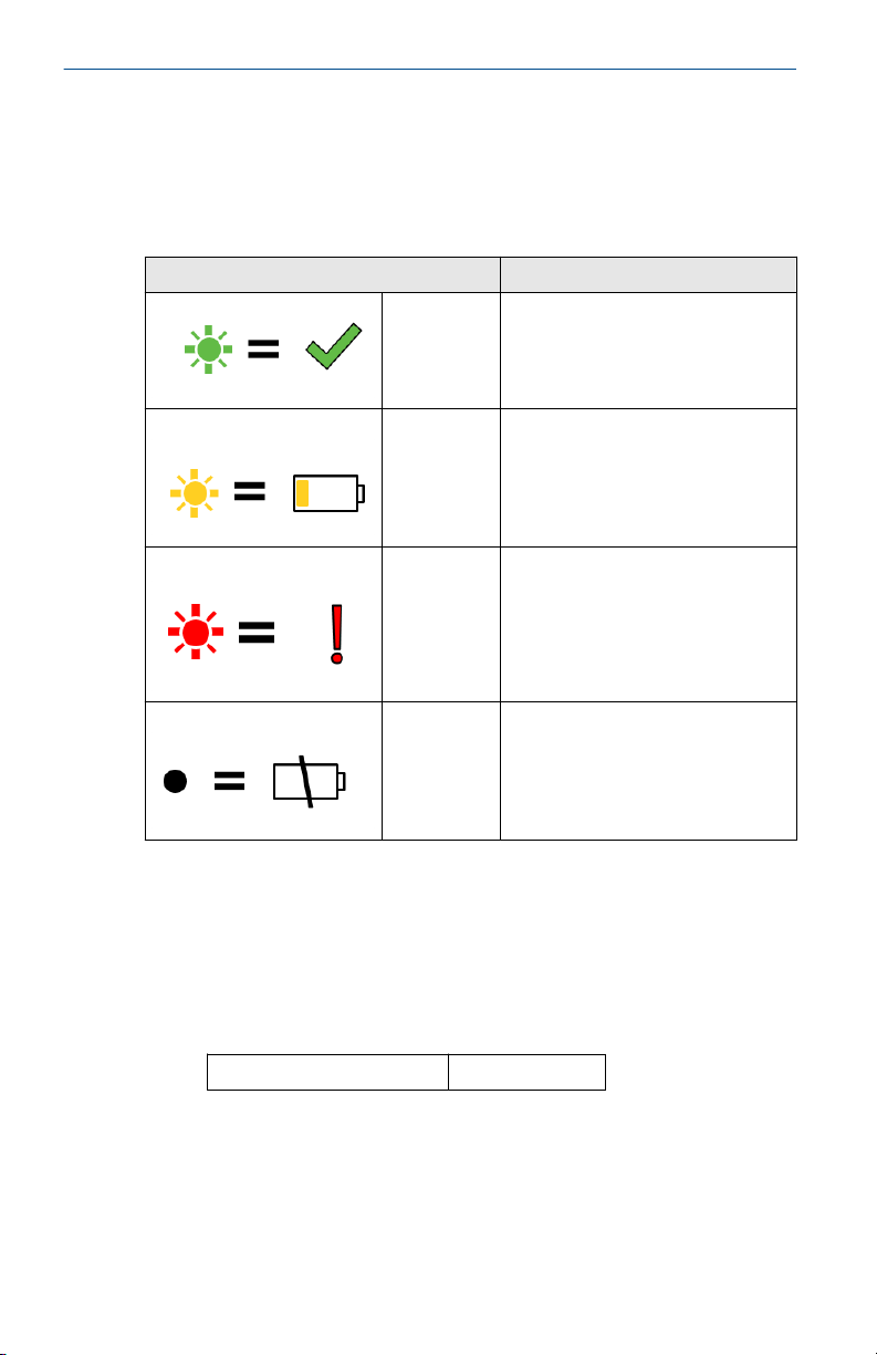
3. Once the power sequence ends, verify that the LED flashes green.
The LED may display several colors; see Device status indicator .
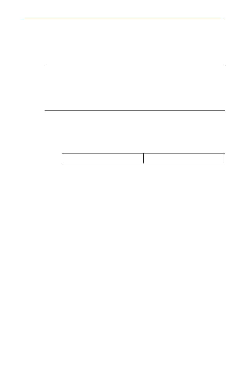
5.3 Connect to the device
Image displaying the device connection diagram
A. Field Communicator
B. HART® Modem
C. AMS Configurator
5.3.1 AMS Configurator
Procedure to connect the AMS Configurator to the smart pressure gauge.
Procedure
1. Start AMS Configurator.
2. From the View menu, select Device Connection View.
3. Double-click the device under the HART® modem.
5.3.2 Field communicator
Procedure to connect the smart pressure gauge to the field communicator.
Procedure
1. Turn on the Field Communicator.
2. From the Main menu, select the HART® symbol.
10 Emerson.com/Rosemount
Page 11
February 2021 Quick Start Guide
5.4 Eliminate mounting effects
Devices are factory-calibrated. Once installed, it is recommended to perform
this step to eliminate potential error caused by mounting position or static
pressure.
Note
See the Rosemount Smart Pressure Gauge Reference Manual for the
following:
• Using AMS Configurator
• Sensor trim function on absolute gauge
Procedure
1. Vent the device.
2. Connect the Field Communicator.
3. From the HOME screen, enter the HART® Fast Key sequence.
Device dashboard Fast Keys 2, 1, 1
4. Follow the commands to perform the procedure.
Quick Start Guide 11
Page 12
Quick Start Guide February 2021
6 Troubleshooting
6.1 Device status indicator
Table 6-1: Status Descriptions
LED color Device status
Green Functioning properly
Amber Battery is low, battery replacement
Red Battery replacement required OR
No color No power, verify ON/OFF switch is in
6.2 Pressure measurement
If the mounting effects have not been eliminated after completing, perform
this alternative procedure for verifying the pressure value.
Procedure
1. From the HOME screen, enter the HART® Fast Key sequence.
recommended
Device is malfunctioning
the on position
Device dashboard Fast Keys
2, 2, 1, 1, 1
2. Follow the commands to perform the procedure.
12 Emerson.com/Rosemount
Page 13

February 2021 Quick Start Guide
7 Product certifications
Rev: 4.0
European Directive Information
A copy of the EC Declaration of Conformity can be found at the end of the
Quick Start Guide. The most recent revision of the EC Declaration of
Conformity can be found at www.rosemount.com.
Ordinary Location Certification from CSA
The product has been examined and tested to determine that the design
meets the basic electrical, mechanical, and fire protection requirements by
CSA, a nationally recognized test laboratory (NRTL) as accredited by the
Federal Occupational Safety and Health Administration (OSHA).
Installing in North America
The US National Electrical Code (NEC) and the Canadian Electrical Code
(CEC) permit the use of Division marked equipment in Zones and Zone
marked equipment in Divisions. The markings must be suitable for the area
classification, gas, and temperature class. This information is clearly defined
in the respective codes.
USA
I5 U.S.A. Intrinsically Safe (IS)
Certificate:
Standards:
Markings:
Special Conditions for Safe Use(X):
1. Do not replace battery when explosive atmosphere is present.
2. Use only 00G45-9000-0001 batteries.
3. The surface resistivity of the housing is greater than 1G Ω. To avoid
4. Substitution of components may impair intrinsic safety.
Quick Start Guide 13
[CSA] 70047656
FM 3600 – 2011, FM 3610 – 2010, UL Standard 50 – Eleventh
Edition, UL 61010-1 – 3rd Edition, ANSI/ISA-60079-0
(12.00.01) – 2013, ANSI/ISA-60079-11 (12.02.01) – 2013,
ANSI/IEC 60529 – 2004
IS CL I, DIV 1, GP A, B, C, D T4; Class 1, Zone 0, AEx ia IIC T4
Ga; T4 (–40 °C ≤ Ta ≤ +70 °C) when installed per Rosemount
drawing 00G45-1020; Type 4X; IP66/67;
electrostatic charge build-up, it must not be rubbed or cleaned with
solvents or a dry cloth.
Page 14

Quick Start Guide February 2021
Canada
I6 Canada Intrinsically Safe (IS)
Certificate:
Standards:
[CSA]70047656
CAN/CSA C22.2 No. 0-10, CAN/CSA C22.2 No. 94-M1991
(R2011), CAN/CSA-60079-0-11, CAN/CSA-60079-11-14, CSA
Std C22.2 No. 60529-05, CAN/CSA-C22.2 No. 61010-1-12
Markings:
Intrinsically Safe for Class I, Division 1, Groups A, B, C, D T4; Ex
ia IIC T4 Ga T4 (–40 °C ≤ Ta ≤ +70 °C) when installed per
Rosemount drawing 00G45-1020; Type 4X; IP66/67;
Special Conditions for Safe Use (X):
1. Do not replace battery when explosive atmosphere is present. Ne pas
remplacer les accumulateurs si une atmosphère explosive peut être
présente.
2. Use only 00G45-9000-0001 batteries. Utiliser uniquement des
accumulateurs 00G45-9000-0001.
3. The surface resistivity of the housing is greater than 1G Ω. To avoid
electrostatic charge build-up, it must not be rubbed or cleaned with
solvents or a dry cloth. La résistivité de surface du boÎtier est
supérieure à un gigaohm. Pour éviter l’accumulation de charge
électrostatique, ne pas frotter ou nettoyer avec des produits solvants
ou un chiffon sec.
4. Substitution of components may impair intrinsic safety. La
substitution de composants peut compromettre la sécurité
intrinsèque.
Europe
I1
Certificate:
Standards:
Markings:
ATEX Intrinsic Safety
Baseefa16ATEX0005X
EN 60079-0: 2012 + A11: 2013, EN 60079-11: 2012
II 1 G Ex ia IIC T4 Ga, T4 (–40 °C ≤ Ta ≤ +70 °C) IP66/67;
Special Conditions for Safe Use (X):
1. The plastic enclosure may constitute a potential electrostatic ignition
risk and must not be rubbed or cleaned with a dry cloth.
2. The measured capacitance between the equipment enclosure and
metallic inline sensor module is 4.7pF. This must be considered only
when the SPG is integrated into a system where the process
connection is not grounded.
14 Emerson.com/Rosemount
Page 15

February 2021 Quick Start Guide
3. Do not change the battery when an explosive atmosphere is present.
4. Only replace battery with Rosemount Part No. 00G45-9000-0001.
International
I7 IECEx Intrinsic Safety
Certificate:
Standards:
Markings:
IECEx BAS 16.0012X
IEC 60079-0: 2011, IEC 60079-11: 2011
Ex ia IIC T4 Ga, T4 (–40 °C ≤ Ta ≤ +70 °C) IP66/67;
Special Conditions for Safe Use (X):
1. The plastic enclosure may constitute a potential electrostatic ignition
risk and must not be rubbed or cleaned with a dry cloth.
2. The measured capacitance between the equipment enclosure and
metallic inline sensor module is 4.7pF. This must be considered only
when the SPG is integrated into a system where the process
connection is not grounded.
3. Do not change the battery when an explosive atmosphere is present.
4. Only replace battery with Rosemount Part No. 00G45-9000-0001.
Brazil
I2 INMETRO Intrinsic Safety
Certificate:
Standards:
UL-BR 16.0826X
ABNT NBR IEC 60079-0:2008+Errata 1:2011, ABNT NBR IEC
60079-11:2009
Markings:
Ex ia IIC T4 Ga, T4 (–40 °C ≤ Ta ≤ +70 °C)
Special Condition for Safe Use (X):
See certificate for special condition.
Japan
I4
Certificate:
Markings:
CML Intrinsic Safety
CML18JPN2350X
Ex ia IIC T4 Ga, T4 (–40 °C ≤ Ta ≤ +70 °C)
Special Condition for Safe Use (X):
See certificate for special condition.
Quick Start Guide 15
Page 16

Quick Start Guide February 2021
Korea
IF KTL Intrinsic Safety
Certificate:
Markings:
16-KA4BO-0540X
Ex ia IIC T4 Ga, T4 (–40 °C ≤ Ta ≤ +70 °C)
Special Condition for Safe Use (X):
See certificate for special condition.
16 Emerson.com/Rosemount
Page 17
February 2021 Quick Start Guide
8 Declaration of conformity
Quick Start Guide 17
Page 18
Quick Start Guide February 2021
18 Emerson.com/Rosemount
Page 19
February 2021 Quick Start Guide
Quick Start Guide 19
Page 20
Quick Start Guide February 2021
9 China RoHS
20 Emerson.com/Rosemount
Page 21

February 2021 Quick Start Guide
Quick Start Guide 21
Page 22

Quick Start Guide February 2021
22 Emerson.com/Rosemount
Page 23

February 2021 Quick Start Guide
Quick Start Guide 23
Page 24

*00825-0100-4145*
00825-0100-4145, Rev. CA
Quick Start Guide
February 2021
For more information:
©
2021 Emerson. All rights reserved.
Emerson Terms and Conditions of Sale are
available upon request. The Emerson logo
is a trademark and service mark of
Emerson Electric Co. Rosemount is a mark
of one of the Emerson family of
companies. All other marks are the
property of their respective owners.
www.emerson.com
 Loading...