

Instruction Manual
556383-Z
March 2002
Model 951A
NO/NOx Analyzer
http://www.processanalytic.com

ESSENTIAL INSTRUCTIONS
READ THIS PAGE BEFORE PROCEEDING!
Rosemount Analytical designs, manufactures and tests its products to meet many national and
international standards. Because these instruments are sophisticated technical products, you
MUST properly install, use, and maintain them to ensure they continue to operate within their
normal specifications. The following instructions MUST be adhered to and integrated into your
safety program when installing, using, and maintaining Rosemount Analytical products. Failure to
follow the proper instructions may cause any one of the following situations to occur: Loss of life;
personal injury; property damage; damage to this instrument; and warranty invalidation.
• Read all instructions prior to installing, operating, and servicing the product.
• If you do not understand any of the instructions, contact your Rosemount Analytical repre-
sentative for clarification.
• Follow all warnings, cautions, and instructions marked on and supplied with the product.
• Inform and educate your personnel in the proper installation, operation, and mainte-
nance of the product.
• Install your equipment as specified in the Installation Instructions of the appropriate In-
struction Manual and per applicable local and national codes. Connect all products to the
proper electrical and pressure sources.
• To ensure proper performance, use qualified personnel to install, operate, update, program,
and maintain the product.
• When replacement parts are required, ensure that qualified people use replacement parts
specified by Rosemount. Unauthorized parts and procedures can affect the product’s performance, place the safe operation of your process at risk, and VOID YOUR WARRANTY.
Look-alike substitutions may result in fire, electrical hazards, or improper operation.
• Ensure that all equipment doors are closed and protective covers are in place, except
when maintenance is being performed by qualified persons, to prevent electrical shock
and personal injury.
The information contained in this document is subject to change without notice.
Teflon® is a registered trademark of E. I. duPont de Nemours and Co., Inc.
Alconox ® is a registered trademark of Alconox, Inc.
Emerson Process Management
Rosemount Analytical Inc.
Process Analytic Division
1201 N. Main St.
Orrville, OH 44667-0901
T (330) 682-9010
F (330) 684-4434
e-mail: gas.csc@EmersonProcess.com
http://www.processanalytic.com

Model 951A
PREFACE...........................................................................................................................................P-1
Definitions ...........................................................................................................................................P-1
Intended Use Statement.....................................................................................................................P-2
Safety Summary .................................................................................................................................P-2
General Precautions For Handling And Storing High Pressure Gas Cylinders .................................P-4
Documentation....................................................................................................................................P-5
Compliances .......................................................................................................................................P-5
1-0 DESCRIPTION AND SPECIFICATIONS..............................................................................1-1
1-1 Overview................................................................................................................................1-1
1-2 Options ..................................................................................................................................1-2
a. Range I.D. .......................................................................................................................1-2
b. Remote Range Change ..................................................................................................1-2
c. Range I.D. and Remote Range Change .........................................................................1-2
d. Sample Pump..................................................................................................................1-2
1-3 Specifications ........................................................................................................................1-3
Instruction Manual
556383-Z
March 2002
TABLE OF CONTENTS
2-0 INSTALLATION ....................................................................................................................2-1
2-1 Facility Preparation................................................................................................................2-1
a. Outline and Mounting Dimensions ..................................................................................2-1
b. Location...........................................................................................................................2-1
c. Power Requirements ......................................................................................................2-1
2-2 Unpacking..............................................................................................................................2-1
2-3 Gas Requirements.................................................................................................................2-1
a. Air Or Oxygen .................................................................................................................2-1
b. Span Gas ........................................................................................................................2-2
2-4 Sample Requirements ...........................................................................................................2-2
2-5 Gas Connections ...................................................................................................................2-2
2-6 Electrical Connections ...........................................................................................................2-6
a. Recorder Output..............................................................................................................2-6
b. Thermocouple Connections for Measuring Temperature of NO2 to NO Converter ........2-6
c. Remote Range Change ..................................................................................................2-6
d. Connections of the Range I. D. Kit..................................................................................2-6
e. Power Connections.........................................................................................................2-6
3-0 STARTUP AND OPERATION ..............................................................................................3-1
3-1 Startup Procedure .................................................................................................................3-1
3-2 Calibration..............................................................................................................................3-3
3-3 Measuring Efficiency Of No2 To No Converter And Adjusting Temperature Setpoint ..........3-4
a. Test Setup for Measurement of Conversion Efficiency...................................................3-4
b. Test Procedure................................................................................................................3-4
c. Subnormal Conversion Efficiency ...................................................................................3-8
d. Replacement of Converter ..............................................................................................3-8
e. Capillaries .......................................................................................................................3-8
f. TEA Scrubber..................................................................................................................3-9
3-4 Routine Operation .................................................................................................................3-9
3-5 Recommended Calibration Frequency..................................................................................3-9
Rosemount Analytical Inc. A Division of Emerson Process Management Contents i

Instruction Manual
556383-Z
March 2002
4-0 THEORY................................................................................................................................4-1
4-1 Principles Of Operation .........................................................................................................4-1
a. Nitric Oxide Determination By Chemiluminescense Method ..........................................4-1
b. NOX Determination..........................................................................................................4-1
c. Ozone Generation ...........................................................................................................4-1
4-2 Analyzer Flow System ...........................................................................................................4-1
a. Flow Of Sample Or Standard Gas To Reaction Chamber..............................................4-1
b. Flow of Air or Oxygen .....................................................................................................4-3
c. Flow System Operating Modes .......................................................................................4-3
d. Converter Bleed Flow .....................................................................................................4-4
4-3 Electronic Circuitry.................................................................................................................4-4
a. Amplifier Board and Associated Circuitry .......................................................................4-5
b. Valve Control Board, Front Panel Mode Switch and Associated Circuitry .....................4-6
c. ±15 Volt Power Supply ....................................................................................................4-6
d. High Voltage Power Supply ............................................................................................4-7
e. Converter Temperature Control Board and Associated Elements .................................4-7
f. Fan Control Circuit ..........................................................................................................4-8
g. Remote Operation Option ...............................................................................................4-8
h. Range I.D. Option ...........................................................................................................4-8
Model 951A
5-0 ROUTINE SERVICING..........................................................................................................5-1
5-1 System Checks And Adjustments .........................................................................................5-1
a. Meter Mechanical Zero ...................................................................................................5-1
b. Amplifier Zero Adjustments.............................................................................................5-1
c. Inter-Range Attenuation Correlation adjustments...........................................................5-1
d. Meter Fullscale Span Adjustment ...................................................................................5-2
e. Overall Sensitivity............................................................................................................5-3
f. Ozone Output..................................................................................................................5-3
g. Background Current........................................................................................................5-3
h. NO2 to NO Converter Temperature Adjustment .............................................................5-4
i. Flow Balance...................................................................................................................5-4
5-2 Servicing Flow System ..........................................................................................................5-5
a. Sample Capillary .............................................................................................................5-5
b. Ozone Restrictor and Capillary .......................................................................................5-6
5-3 NO2 To NO Converter............................................................................................................5-7
a. Replacing ........................................................................................................................5-7
5-4 Photomultiplier/Reaction Chamber........................................................................................5-8
a. Cleaning Reaction Chamber...........................................................................................5-8
b. Photomultiplier Tube and Housing..................................................................................5-10
5-5 Servicing Electronic Circuitry.................................................................................................5-11
6-0 REPLACEMENT PARTS ......................................................................................................6-1
6-1 Circuit Board Replacement Policy .........................................................................................6-1
6-2 Matrix .....................................................................................................................................6-1
6-3 Replacement Parts ................................................................................................................6-2
a. Pneumatics .....................................................................................................................6-7
b. Converter Assembly........................................................................................................6-8
c. Low Tempco Option........................................................................................................6-10
7-0 RETURN OF MATERIAL ....................................................................................................7-1
7-1 Return Of Material .................................................................................................................7-1
7-2 Customer Service ..................................................................................................................7-1
7-3 Training..................................................................................................................................7-1
ii Contents Rosemount Analytical Inc. A Division of Emerson Process Management

Model 951A
Figure 1-1. Model 951A NO/NOX Analyzer .............................................................................. 1-1
Figure 2-1. Model 951A Outline and Mounting Dimensions .................................................... 2-3
Figure 2-2. Front Panel Indicators and Controls ...................................................................... 2-4
Figure 2-3. Controls and Adjustments Located Behind Swing Out Front Panel...................... 2-4
Figure 2-4. Rear Panel............................................................................................................. 2-4
Figure 2-5. Remote Range Kit Installed................................................................................... 2-7
Figure 2-6. Typical Interconnection of Remote Range Kit ....................................................... 2-7
Figure 3-1. Amplifier Board Adjustments ................................................................................. 3-3
Figure 3-2. Measuring Efficiency of NO2 to NO Converter ...................................................... 3-7
Figure 3-3. Conversion Efficiency as a Function of Converter Temperature........................... 3-8
Figure 4-1. Schematic Flow Diagram of Model 951A .............................................................. 4-2
Figure 4-2. Functional Schematic Diagram of Electronic Signal Circuitry ............................... 4-5
Figure 5-1. Amplifier Board ......................................................................................................5-2
Figure 5-2. NO2 to NO Converter Assembly ............................................................................ 5-7
Figure 5-3. Reaction Chamber/Photomultiplier Assembly ....................................................... 5-9
Figure 5-4. Reaction Chamber Assembly and Phototube Housing ......................................... 5-9
Figure 5-5. Terminal Chassis Assembly Wiring Diagram ...................................................... 5-12
Figure 6-1. Model 951A – Exploded View................................................................................ 6-3
Figure 6-2. Model 951A – Exploded View (continued)............................................................. 6-4
Figure 6-3. Model 951A – Exploded View (continued)............................................................. 6-5
Figure 6-4. Electronics ............................................................................................................. 6-6
Figure 6-5. Front Panel Pneumatic Components..................................................................... 6-7
Figure 6-6. Converter Components.......................................................................................... 6-8
Figure 6-7. Ozone Generator Components.............................................................................. 6-9
Figure 6-8. Tempco Retrofit Component Location................................................................. 6-10
Instruction Manual
556383-Z
March 2002
LIST OF ILLUSTRATIONS
LIST OF TABLES
Table 2-1. Model 951A Controls and Adjustments ................................................................. 2-5
Table 3-1. Proper Gas Supply Pressures for Various Levels of Sample NOX........................ 3-2
Rosemount Analytical Inc. A Division of Emerson Process Management Contents iii

Instruction Manual
556383-Z
March 2002
Model 951A
DRAWINGS
619604 Schematic Diagram, Computer Interface
619710 Schematic Diagram, ±15V Power Supply
641871 Schematic Diagram, Temp Control
649819 Schematic Diagram, Amplifier Board
649822 Diagram, Tubing - Model 95A
649834 Schematic Diagram, 951A NO/NOx Analyzer
649835 Pictorial Wiring Diagram, Model 951A NO/NOx Analyzer
649958 Flow Diagram, Model 951A
652423 Schematic Diagram, Power Supply
652834 Schematic Diagram, Power Supply - Thermocooler
652838 Pictorial Wiring Diagram, Low Tempco Option
654348 Schematic Diagram, Hi Voltage Board Assembly
656313 Schematic Diagram, Valve Control Board
780350 Schematic Diagram, 4-20mA 0-5V Option
780726 Wiring Diagram, 4-20mA 0-5V Option
780727 Installation Drawing, Model 951A w/4-20mA 0-5V Option
780809 Wiring Diagram, 4-20mA 0-5V Option and Low Tempco
(Located In Rear Of Manual)
iv Contents Rosemount Analytical Inc. A Division of Emerson Process Management

Instruction Manual
Model 951A
PREFACE
The purpose of this manual is to provide information concerning the components, functions, installation and maintenance of the Model 951A .
Some sections may describe equipment not used in your configuration. The user should become
thoroughly familiar with the operation of this analyzer before operating it. Read this instruction
manual completely.
DEFINITIONS
The following definitions apply to DANGERS, WARNINGS, CAUTIONS and NOTES found throughout
this publication.
DANGER .
Highlights the presence of a hazard which will cause severe personal injury, death, or substantial
property damage if the warning is ignored.
556383-Z
March 2002
WARNING .
Highlights an operation or maintenance procedure, practice, condition, statement, etc. If not
strictly observed, could result in injury, death, or long-term health hazards of personnel.
CAUTION.
Highlights an operation or maintenance procedure, practice, condition, statement, etc. If not
strictly observed, could result in damage to or destruction of equipment, or loss of effectiveness.
NOTE
Highlights an essential operating procedure,
condition or statement.
Rosemount Analytical Inc. A Division of Emerson Process Management Preface P-1

Instruction Manual
556383-Z
March 2002
Model 951A
INTENDED USE STATEMENT
The Model 951A NO/NOx Analyzer is intended for use as an industrial process measurement device
only. It is not intended for use in medical, diagnostic, or life support applications, and no independent agency certifications or approvals are to be implied as covering such applications.
SAFETY SUMMARY
If this equipment is used in a manner not specified in these instructions, protective systems may be
impaired.
AUTHORIZED PERSONNEL
To avoid explosion, loss of life, personal injury and damage to this equipment and on-site property,
do not operate or service this instrument before reading and understanding this instruction manual
and receiving appropriate training. Save these instructions.
DANGER.
ELECTRICAL SHOCK HAZARD
Do not operate without doors and covers secure.. Installation requires access to live parts which
can cause death or serious injury.
For safety and proper performance this instrument must be connected to a properly grounded
three-wire source of power.
DANGER.
ULTRA VIOLET LIGHT HAZARD
UV light from the ozone generator can cause permanent eye damage. DO NOT LOOK DIRECTLY AT
THE UV SOURCE IN THE OZONE GENERATOR. Use of UV filtering glasses is recommended.
P-2 Preface Rosemount Analytical Inc. A Division of Emerson Process Management

Instruction Manual
Model 951A
DANGER.
OZONE HAZARD
This instrument generates ozone while operating. Ozone is toxic by inhalation and is a strong irritant to the throat and lungs. Ozone is also a strong oxidizing agent. Its presence is detected by a
characteristic pungent odor.
The instrument EXHAUST outlet contains ozone and nitrogen dioxide which is toxic by inhalation.
The BYPASS outlet contains various oxides of nitrogen, and if the sample source is from the exhaust of an internal combustion engine, it may contain unburned hydrocarbons and carbon monoxide which is highly toxic and, depending on duration of exposure, can cause headache, nausea,
loss of consciousness and death.
Avoid any inhalation of the internally generated ozone, sample, EXHAUST and BYPASS discharge.
Keep all tubing fittings checked for tightness to avoid internal leaks.
Connect rear panel EXHAUST and BYPASS outlets to outside vent via separate lines 1/4 inch
(6.3mm) or larger. Use only Teflon or stainless steel tubing.
556383-Z
March 2002
WARNING.
PARTS INTEGRITY
Tampering with or unauthorized substitution of components may adversely affect the safety of this
instrument. Use only factory approved components for repair.
CAUTION
AIR FLOW
Do not operate instrument without air flow to the ozonator; plugging of the filter will result.
CAUTION.
PRESSURIZED GAS
This unit requires periodic calibration with a known standard gas. It also may utilizes a pressurized carrier gas, such as helium, hydrogen, or nitrogen. See General Precautions for Handling and
Storing High Pressure Gas Cylinders, page P-4.
Rosemount Analytical Inc. A Division of Emerson Process Management Preface P-3

Instruction Manual
556383-Z
March 2002
Model 951A
GENERAL PRECAUTIONS FOR HANDLING AND STORING HIGH
PRESSURE GAS CYLINDERS
Edited from selected paragraphs of the Compressed Gas Association's "Handbook of Compressed
Gases" published in 1981
Compressed Gas Association
1235 Jefferson Davis Highway
Arlington, Virginia 22202
Used by Permission
1. Never drop cylinders or permit them to strike each other violently.
2. Cylinders may be stored in the open, but in such cases, should be protected against extremes of
weather and, to prevent rusting, from the dampness of the ground. Cylinders should be stored in the
shade when located in areas where extreme temperatures are prevalent.
3. The valve protection cap should be left on each cylinder until it has been secured against a wall or
bench, or placed in a cylinder stand, and is ready to be used.
4. Avoid dragging, rolling, or sliding cylinders, even for a short distance; they should be moved by using a
suitable hand-truck.
5. Never tamper with safety devices in valves or cylinders.
6. Do not store full and empty cylinders together. Serious suckback can occur when an empty cylinder is
attached to a pressurized system.
7. No part of cylinder should be subjected to a temperature higher than 125°F (52°C). A flame should
never be permitted to come in contact with any part of a compressed gas cylinder.
8. Do not place cylinders where they may become part of an electric circuit. When electric arc welding,
precautions must be taken to prevent striking an arc against the cylinder.
P-4 Preface Rosemount Analytical Inc. A Division of Emerson Process Management

Instruction Manual
Model 951A
DOCUMENTATION
The following Model 951A NO/NOx Analyzer instruction materials are available. Contact Customer Service Center or the local representative to order.
556383 Instruction Manual (this document)
COMPLIANCES
This product may carry approvals from several certifying agencies, for use in non-hazardous, indoor locations.
97-C218
556383-Z
March 2002
Rosemount Analytical Inc. A Division of Emerson Process Management Preface P-5

Instruction Manual
556383-Z
March 2002
Model 951A
P-6 Preface Rosemount Analytical Inc. A Division of Emerson Process Management
Model 951A
Instruction Manual
556383-Z
March 2002
SECTION 1
DESCRIPTION AND SPECIFICATIONS
1-1 OVERVIEW
The Model 951A NO/NOX Analyzer continuously analyzes a flowing gas sample performing one of two switch selectable
determinations:
1. Nitric oxide (NO); or
2. Combined nitric oxide (NO) and nitrogen
dioxide (NO
tion [NO
) designated NOX. By defini-
2
] = [NO] + [NO2].
X
Typical applications include analyzing vehicular exhaust emissions from internal combustion engines and monitoring the effluent
from stationary (stack) sources
The analyzer utilizes the chemiluminescent
method of detection In the nitric oxide determination, sample NO is quantitatively converted into NO
by gas-phase oxidation with
2
molecular ozone produced within the analyzer
from air or oxygen supplied by an external
cylinder. A characteristic of this reaction is
the elevation of approximately 10% of the NO
molecules to an electronically-excited state,
followed by immediate reversion to the
non-excited state accompanied by emission of
photons.
The emitted photons impinge on a photomultiplier detector generating a low-level DC current. The current is amplified to drive a front
panel meter and an accessory potentiometric
recorder if desired.
To minimize noise and reduce dark current,
the photomultiplier tube is mounted in a thermoelectrically-cooled housing with temperature held constant at about 59
o
F (15oC).
Control circuitry is contained in the 652831
Cooler Temperature Controller/Power Supply
Assembly. The power supply circuit provides
a high-current source of DC voltage. A thermistor sensor attached to the housing, and an
associated switching transistor, control a pass
transistor, providing closely regulated on-off
control.
Attached to the cooler housing is thermal fuse
F3, setpoint 150
o
F (65oC). This fuse protects
the thermoelectric cooler against the over-
2
heating that otherwise could occur as a result
of excessively high ambient temperature or
failure of a fan.
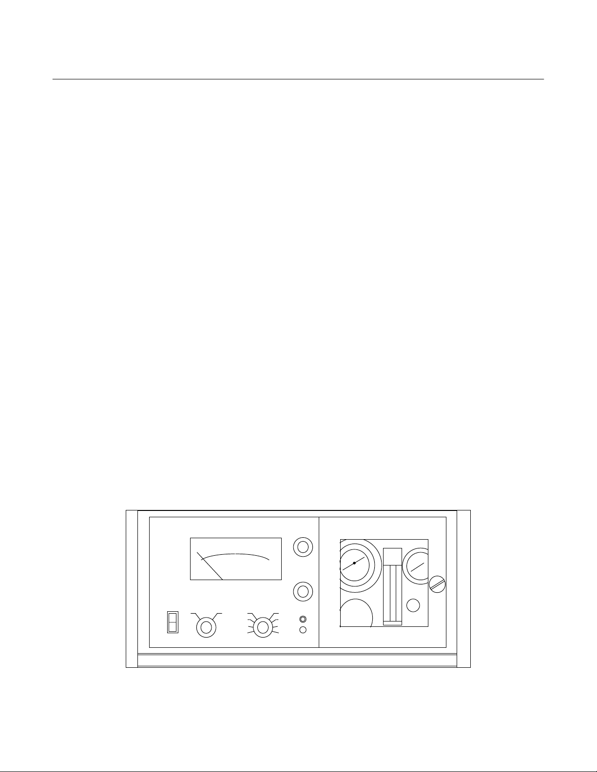
SPAN
ZERO
ON
OFF
Rosemount Analytical
MODE
NO NOx
PPM RANGE
250 1000
100 2500
25 10000
10 AUTO
CONVERTER
ADJUST
Model 951A NO/NOx Analyzer
Figure 1-1. Model 951A NO/NOX Analyzer
Rosemount Analytical Inc. A Division of Emerson Process Management Description and Specifications 1-1

Instruction Manual
556383-Z
March 2002
Model 951A
CAUTION
EXCESSIVE HEAT
Do not operate this analyzer without the air
duct covering the cooling fins of the thermoelectric cooler. Excessive heat may
damage the cooling devices. The cooler
indicator lamp DS1 (mounted on the upper
left side of the inner flow regulator panel
and can be viewed through the window)
will cycle on and off until a control point is
reached.
Analyzer functioning for the NOX determination is identical to that described above for the
NO determination except that, before entry
into the reaction chamber, the sample is
routed through a converter where the NO
2
component is dissociated to form NO. Instrument response is proportional to total NO
in the converted sample, that is the sum of the
NO present in the original sample plus the NO
produced by dissociation of NO
.
2
To minimize system response time an internal
sample-bypass feature provides high-velocity
sample flow through the analyzer.
the different thermal conductivity's of the
individual components of the sample
stream. The method is especially well
suited to analysis of two-component sample streams. However, analysis of
multi-component streams is possible if the
various components of the background
gas occur in relatively constant ratio, or
have similar thermal conductivity's.
b. Remote Range Change
For applications where remote operation
of the analyzer is desired, as in an emission test console, the Remote Range
Change Option may be used. This option
permits either the operator or a computer
to override and disable the front panel
MODE and PPM RANGE Switches and
thus to control selection of: (a) NO or NO
mode, and (b) ppm range.
The unit consists of an electrical plug
connector with plug-in logic card and harness for connection to a rear panel terminal strip on the analyzer.
c. Range I.D. and Remote Range Change
X
The electronic circuitry is modularized, utilizing plug-in printed circuit boards with solid
state components and test jacks for easy
troubleshooting and replacement.
If desired, the Model 951A may be factory
equipped with various optional features in addition to the standard features of the basic instrument. Brief descriptions of the principal
options are given in the following section.
1-2 OPTIONS
a. Range I.D.
This option provides contact closure signals that enable a computer or other external device to identify the setting of the
front panel PPM RANGE Switch. The
Model 951A is designed to continuously
measure the concentration of a single
component of interest in a flowing gas
mixture. The measurement is based on
The Range I.D./Remote Range Change
Option is a combination of the Range I.D.
and Remote Range Change options. This
option is compatible with a user supplied
remote control system employing a 24
VDC digital output and input for analyzer
range control and analyzer range sense,
respectively. It is completely integral
within the analyzer and provides a terminal strip on the rear of the analyzer for
connections of the user cable.
d. Sample Pump
The basic Model 951A is designed to accept pressurized samples. To permit
analysis of gases at atmospheric or subatmospheric pressure the analyzer may
be equipped with an optional, internally
mounted sample pump. This option is not
available on Low Tempco versions of the
951A. An external, accessory pump can
be ordered instead.
1-2 Description and Specifications Rosemount Analytical Inc. A Division of Emerson Process Management

Model 951A
1-3 SPECIFICATIONS
Catalog Number ............................ 193702 Model 951A NO/NOX Analyzer
Ranges .......................................... Selectable fullscale range of 10, 25, 100, 250, 1000, 2500 and
Sensitivity ...................................... 0.1 ppm on 10 ppm range
Linearity ......................................... ±1% of fullscale
Response Time (Electronic Plus Flow)
Standard Sample Capillary.... Approximately one second on all ranges except 10 ppm.
Auxiliary Sample Capillary..... Five seconds on all ranges.
Precision........................................ ±5% of fullscale
Stability
Zero ....................................... 1% of fullscale in 24 hours
Span ...................................... 1% of fullscale in 24 hours
Detector Operating Temperature .. Atmospheric
Recorder Output............................ Selectable output of 10 millivolts, 100 millivolts, 1 volt or 5 volts
Ambient Temperature.................... 40°F to 100°F (4.4°C to 37.7°C)
Electrical Power Requirements ..... 107 to 127 VAC, 50/60 Hz, 1000 watts
Dimensions.................................... 9.0 x 17.8 x 22.0 inches (228.6 x 450.9 x 558.8mm) HxWxD
Weight ........................................... 76 lbs. (34.5 kg)
Instruction Manual
556383-Z
March 2002
10,000 parts per million
The specified linearity is obtainable throughout the operating range,
contingent upon use of an appropriate combination of oxygen
source gas, gas pressure settings and electronic adjustments.
Approximately three seconds on 10 ppm range.
For such applications as monitoring stack sources, where comparatively slow response is desired, an internal switch provides an optional electronic response time of approximately 10 seconds to 90%
of fullscale on all ranges.
Rosemount Analytical Inc. A Division of Emerson Process Management Description and Specifications 1-3

Instruction Manual
556383-Z
March 2002
Model 951A
1-4 Description and Specifications Rosemount Analytical Inc. A Division of Emerson Process Management

Model 951A
Instruction Manual
556383-Z
March 2002
SECTION 2
INSTALLATION
2-1 FACILITY PREPARATION
Sections 2-1a through 2-1c provide information that may be required prior to installation
of the analyzer.
a. Outline and Mounting Dimensions
Significant dimensions are shown in Figure 2-1.
b. Location
Install analyzer in a clean area, not subject to excessive vibration or extreme
temperature variations .
Preferably, the analyzer should be
mounted near the sample stream, to
minimize sample transport time. A circuit
controlled by a thermal switch holds internal temperature of the analyzer to the correct operating temperature for ambient
temperatures in the range 40
o
(4.4
C to 37.7oC). Temperatures outside
these limits necessitate use of special
temperature controlling equipment or environmental protection.
Preferably, the cylinders of air (or oxygen)
and span gas should be located in an
area of relatively constant ambient temperature.
c. Power Requirements
Electrical power requirements are 107 to
127 VAC, 50/60 Hz, 1000 watts.
2-2 UNPACKING
Unpack instrument carefully. Preparatory to
shipment, the photomultiplier tube housing
and the sample pump (if instrument is so
equipped) are immobilized with hold down
screws, inserted from the bottom of the instrument and marked with red paint for identification. The hold down screws must be
o
F to 100oF
removed prior to operation of the instrument.
In the event the instrument is ever returned to
the factory, these screws must be replaced to
ensure safe shipment.
2-3 GAS REQUIREMENTS
CAUTION
HIGH PRESSURE GAS CYLINDERS
This instrument requires use of oxygen
and a known standard gas in high pressure cylinders. Refer to Handling and
Storing High Pressure Gas Cylinders located on page P-4.
a. Air or Oxygen
This is used as both (a) oxygen source for
generation of the ozone required for the
chemiluminescent reaction, and (b) standard gas for zero calibration. Gas for both
purposes may be supplied from a single
cylinder and routed through a tee. Alternatively, two separate cylinders may be
used.
Oxygen is usable in all applications. Air is
suitable for the oxygen source only if the
desired fullscale operating range is 2500
ppm or less. Breathing grade oxygen or
air is recommended. Clean, dried ambient
air containing less than 0.1 ppm nitric oxide may be used, provided that its dewpoint is below -10
insufficiently dried, or contains excessive
nitric oxide, instrument response will not
be linear to 2500 ppm.
o
F (-23oC). If air is
Rosemount Analytical Inc. A Division of Emerson Process Management Installation 2-1

Instruction Manual
556383-Z
March 2002
Model 951A
b. Span Gas
This is a standard gas of accurately
known composition, used to set an upscale calibration point.
Alternative span gases are:
1. The usual span gas is NO in a background of nitrogen.
2. For span check or adjustment in the
NO
mode, the span gas may be NO
X
in a background of air or nitrogen.
3. For convenient calibration in either
the NO or NO
mode, the span gas
X
may be a cylinder gas mixture consisting of known concentrations of
both NO and NO
in a background of
2
nitrogen.
NOTE
For maximum calibration accuracy, the
concentration of NO and/or NO
span gas should be as near as possible to that in the sample gas. Also, the
span gas should be supplied to the
rear panel SAMPLE inlet at the same
pressure as the sample gas. To ensure
constant pressure, a pressure regulator may be utilized immediately upstream from the SAMPLE inlet.
in the
2
tory can provide technical assistance if desired .
Proper supply pressures for sample and span
gases depend on whether or not the analyzer
is equipped with the optional 632748 Sample
Pump:
For the basic Model 951A, without sample
pump, sample must be supplied to the SAMPLE inlet at a pressure of 5 to 10 psig (34.5 to
69 kPa). This ensures that the normal bypass
2
flow of two liters per minute will be obtainable
by adjustment of the BYPASS Needle Valve.
(Proper bypass flow is essential for rapid
system response and stable flow into reaction
chamber.)
For an analyzer equipped with sample pump,
the acceptable pressure range at the SAMPLE inlet is 0 to 5 psig (0 to 34.5 kPa). The
pump pressurizes the sample to between 5
and 10 psig (34.5 to 69 kPa) for supply to the
internal flow system.
2-5 GAS CONNECTIONS
1. Remove plugs and caps from all inlet and
outlet fittings. See Figure 2-4.
2. Connect EXHAUST outlet to outside vent
via tubing with O.D. of 1/4 inch (6.3mm)
or larger.
Preferably, each gas used should be supplied from a tank or cylinder equipped
with a clean, non-corrosive type two stage
regulator. In addition, a shut-off valve is
desirable. If possible, install the gas cylinders in an area of relatively constant ambient temperature.
2-4 SAMPLE REQUIREMENTS
The Sample must be relatively clean and dry
before entering the analyzer. In general, before admission to the analyzer, the sample
should be filtered to 2 microns and should
have a dewpoint below 90
2-2 Installation Rosemount Analytical Inc. A Division of Emerson Process Management
o
F (32oC). The fac-
3. Connect external lines from air (or oxygen) cylinder and sample source to corresponding rear panel inlet ports. For
sample line, stainless steel tubing is recommended.
4. Adjust regulator on air (or oxygen) cylinder for output pressure of 35 to 40 psig
(251 to 276 kPa).
5. Supply sample gas to rear panel SAMPLE
inlet at appropriate pressure: 5 to 10 psig
(34.5 to 69 kPa) for basic analyzer without
sample pump; 0 to 5 psig (0 to 34.5 kPa)
for analyzer with pump.

Model 951A
[
]
[
]
Instruction Manual
556383-Z
March 2002
19.0
[482]
8.7
[222]
8.7
[221]
DIMENSIONS
Inch
mm
3. ALLOW 16 INCHES IN FRONT OF INSTRUMENT FOR DOOR SWING.
2. ALLOW 12 INCHES MINIMUM CLEARANCE
ABOVE INSTRUMENT FOR MAINTENANCE..
1. RECOMMENDED MOUNTING HARDWARD:
10-32 MACHINE SCREWS (SUPPLIED BY
CUSTOMER).
Figure 2-1. Model 951A Outline and Mounting Dimensions
[228]
7.0
[178]
1.25
[32]
9.0
4.5
114
18.3
[465]
2.0
[51]
18.3
[465]
18.3
[465]
18.3
[465]
20.2
[513]
6.0
[152]
18.3
[465]
RECOMMENDED PANEL CUTOUT
1.25
[32]
1.0
[25.4]
2.8
[70]
8.5
[216]
4.6
[118]
∅
[63]
6.6
168
.25
6 PLC'S
Rosemount Analytical Inc. A Division of Emerson Process Management Installation 2-3
Instruction Manual
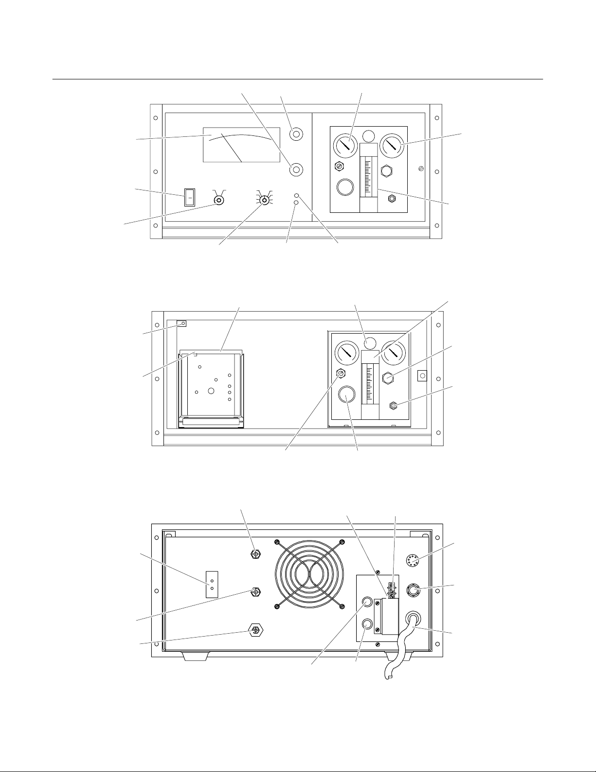
A
556383-Z
March 2002
Model 951A
AC Power
On/off Switch
Mode
Switch
Photomultiplier High
Voltage Interlock
Switch
Recorder Output
Select Switch
Zero Adjust
ON
Rosemount Analytical
PPM Range Switch
Span Adjust
SPAN
ZERO
FLOW
PPM RANGEMODE
250
100
25
10
1000
2500
10000
AUTO
CONVERTER
ADJUST
BALANCE
Converter Adjust
Converter Indicator
Model 951A NO/NOx Analyzer
Figure 2-2. Front Panel Indicators and Controls
Response Time Selector Switch
10
5
FAST SLOW
100
1
RESPONSE
MV
V
REC
OUTPUT
R22
R34
CALIB
R16
R33
R31
R6
INPUT
R32
Bypass Needle Valve
FLOW
BALANCE
Sample Pressure Gauge
B
Y
P
A
S
S
B
Y
P
A
S
S
OZONE
OZONE
OFF
OZONE
OZONE
OFF
Ozone Pressure
Gauge
Bypass Flowmeter
Bypass Flowmeter
Ozone Pressure
Regulator
Ozone Off Pushbutton Switch
Figure 2-3. Controls and Adjustments Located Behind Swing Out Front Panel
Thermocouple
Connector TB9
ir Inlet
Exhaust
Rosemount Analytical
Flow Balance Needle Valve
Sample Inlet
Recorder Connection TB4-2
Fuse F1 Fuse F2
Figure 2-4. Rear Panel
Model 951A NO/NOx Analyzer
Sample Backpressure Regulator
Recorder Connection TB4-1
Range I.D. Connector J10 (option)
Cable Gland For Recorder Cable
AC Power Cable
2-4 Installation Rosemount Analytical Inc. A Division of Emerson Process Management

Model 951A
CONTROL FUNCTION
ON/OFF Controls AC power to all components in instrument
MODE Switch For selection of NO or NOX
Readout of NO or NOX in ppm as selected with MODE switch. Upper scale is
Meter
PPM RANGE Switch Select fullscale range for meter and recorder
CONVERTER
ADJUST
ZERO
SPAN
SAMPLE backpressure regulator and pressure gauge
BYPASS Flowmeter and Needle Valve
OZONE pressure regulator and
gauge
OZONE OFF switch
FLOW BALANCE needle valve
RESPONSE TIME selector
switch
RECORDER OUTPUT selector
switch
Meter mechanical zero
Photomultiplier High Voltage
Interlock Switch
graduated 0 to 100 for use with 10, 100, 1000, and 10,000 ppm ranges. Lower
scale is graduated 0 to 25 for use with 25 and 2500 ppm ranges.
LED illuminates during application of power to converter heater. When Converter reaches temperature equilibrium, LED will go off and on at intervals of
about 2 seconds, indicating correct temperature control.
Through-panel screwdriver adjustment of converter temperature. Should be set
for temperature that yields optimum combination of high efficiency for the NO
NO conversion and extended life for the catalytic converter. Optimum temperature differs from one instrument to another, see Section 3-3, page 3-4.
Set zero point on meter scale or recorder chart. With MODE switch in NO position and zero air supplied to SAMPLE inlet, ZERO Control is adjusted for zero
reading.
Set upscale calibration point on meter scale or recorder chart. MODE switch is
at NO or NO
NO/NO
and suitably pressurized standard gas of accurately known
X
content is supplied to SAMPLE inlet. With PPM RANGE switch set to
X
the appropriate range for the span gas, the SPAN control is adjusted to correct
reading on meter or recorder.
Adjustment and indication of pressure (and therefore flow) of sample or standard
gas routed through sample capillary, and into reaction chamber. Proper setting
dependent on operating range. See Table 3-1, page 3-2.
Bypass flow indication and adjustment for sample or standard gas to SAMPLE
inlet. Setting of 2 L/min. is recommended to ensure rapid response and optimum functioning of sample backpressure regulator
Pressure adjustment and indication for air or oxygen supplied to AIR inlet for use
as oxygen source for internal ozone generator. Oxygen is usable for all ranges.
Air is usable only for 2500 ppm range or lower. Proper pressure setting dependent on operating range, see Table 3-1, page 3-2.
Removes AC power to ultraviolet source lamp in ozone generator. Power is
OFF when switch indicator is red.
Use to equalize pressure drop for NO and NOX legs of the internal flow system.
Criterion for correct adjustment is an NO2 free nitric oxide standard gas should
give equal readings of ppm for NO and NO
check , if NO
free standard gas is unavailable, is to verify that the reading on
2
modes. An alternate flow balance
X
the SAMPLE pressure gauge is the same for NO and NO
Select either FAST or SLOW electronic response. When set to FAST, electronic
response time (for 0 to 90% of fullscale) is then approximately one second for all
ranges except 10 ppm, which is approximately three seconds. When set to
SLOW (as in monitoring stack sources), electronic response time 0 to 90% of
fullscale) is approximately ten seconds for all ranges.
To select output of 10 mV, 100 mV, 1V or 5 V for a potentiometric recorder.
Located on rear of meter. With AC power OFF, meter should read zero. If not
use screw adjustment on meter.
When analyzer front panel is open, photomultiplier high voltage power supply is
automatically shut off.
Instruction Manual
556383-Z
March 2002
to
2
modes.
X
Table 2-1. Model 951A Controls and Adjustments
Rosemount Analytical Inc. A Division of Emerson Process Management Installation 2-5

Instruction Manual
556383-Z
March 2002
Model 951A
2-6 ELECTRICAL CONNECTIONS
a. Recorder Output
If a recorder is used, connect leads to
terminals marked REC 1 (+) and 2 (-) on
TB4 (Figure 2-4, page 2-4). (Note that,
within the analyzer, the negative recorder
output terminal is connected to ground.)
Set REC OUTPUT Selector Switch SW1
(Figure 2-3, page 2-4) to the recorder
span: 10 mV, 100 mV, 1 VDC or 5 VDC.
b. Thermocouple Connections for Meas-
uring Temperature of NO
Converter
Temperature of the NO2 to NO converter
may be monitored by connecting a customer supplied millivolt meter to thermocouple connector TB9 located on the rear
panel (Figure 2-4, page 2-4). The position
of the thermocouple in the converter bundle will influence the actual temperature
readout.
c. Remote Range Change
to NO
2
The MAN/AUTO RANGE Switch provides
the choice of local or remote selection of
operating range. With switch at MAN,
range selection is under control of the
front panel PPM RANGE Switch. With
switch at AUTO, the front panel PPM
RANGE Switch is disabled; range selection is remotely controlled, by either the
operator or a computer, via contact closure signals applied to terminals on TB6.
Control at TB5 and TB6 is accomplished
by a contact closure from the terminal
marked COM (for common) to the terminal marked with the name of the desired
function. Contact closure requirements
are 25 mA at 15 VDC.
d. Connections of the Range I. D. Kit
The Range I.D. option provides contact
closure signals that permit a computer or
other external device to identify the position selected manually with the front panel
PPM RANGE Switch. The cable is connected to PPM RANGE Switch SW1 and
extends to connector J10 mounted on the
rear of the case (Figure 2-4, page 2-4).
The Remote Range Change Kit, Figure
2-5 page 2-7, consists of a plug-in
Adapter Board plus attached harness and
rear terminal plate.
The Adapter Board has two two-position
slide switches: the MAN/AUTO MODE
Switch and the MAN/AUTO RANGE
Switch.
The MAN/AUTO MODE Switch provides
the choice of local or remote control of the
NO/NO
associated with the NO
Mode Switching Solenoid Valve,
X
to NO converter.
2
With switch at MAN, the function is under
control of the front panel MODE Switch.
With switch at AUTO, the front panel
MODE Switch is disabled; the function is
then remotely controlled, by either the operator or a computer, via contact closure
signals applied to terminals on TB5.
The pin-out connections of J10 are as
follows:
Pin A 10 ppm
Pin B 25 ppm
Pin C 100 ppm
Pin D 250 ppm
Pin E 1000 ppm
Pin F 2500 ppm
Pin H 10000 ppm
Pin J Wiper
e. Power Connections
Connect power cord to an AC source of
107 to 127 volts, 50/60 Hz. If power outlet
does not have third (ground) contact, use
an adapter to provide proper grounding.
2-6 Installation Rosemount Analytical Inc. A Division of Emerson Process Management

Model 951A
y
Computer Adapter
Board
Auto/Man Range
Switch
10
5
FAST SLOW
100
1
MV
REC
RANGE
AUTO
MAN
RESPONSE
V
OUTPUT
R22
R34
CALIB
R16
R33
INPUT
R31
R32
MODE
AUTO
MAN
R6
Rosemount Analytical
Electronics
Assembly
DC Harness (J1)
Auto/Man Mode
Switch
NOX
SPAN
ZERO
Instruction Manual
10
25
100
1000
500
2
10,000
556383-Z
March 2002
Computer Adapter Board installed on
Interconnect Board of the Electronics
Assembly
Figure 2-5. Remote Range Kit Installed
Terminal
Assembl
Remote Mode
Select Switch
NOx
SPAN
ZERO
COM
10
25
100
250
1000
2500
10,000
COM
Terminal Assembly mounted
on rear panel of Model 951A
Remote Range
Select Switch
With all contacts of Range Select Switch
open, analyzer is on 250 ppm range.
Figure 2-6. Typical Interconnection of Remote Range Kit
Rosemount Analytical Inc. A Division of Emerson Process Management Installation 2-7

Instruction Manual
556383-Z
March 2002
Model 951A
2-8 Installation Rosemount Analytical Inc. A Division of Emerson Process Management

Model 951A
Instruction Manual
556383-Z
March 2002
SECTION 3
STARTUP AND OPERATION
Preparatory to startup and operation, a thorough
familiarization with Table 2-1 (page 2-5), Figure
2-2 (page 2-4), Figure 2-3 (page 2-4) and Figure
2-4 (page 2-4) is recommended. These figures
give locations and brief descriptions of operating
controls. For more detailed information on controls, refer to Section 4.
3-1 STARTUP PROCEDURE
Following are detailed stepwise instructions
on startup and calibration. For convenience, condensed instructions for startup,
routine calibration and normal operation are
provided at the front of this manual.
WARNING
OZONE HAZARD
When instrument power is on, the ultraviolet source sample is energized, converting a portion of the oxygen
contained with the ozonator into ozone.
With normal flow through the ozonator,
the ozonated air or oxygen is continuously swept though the ozonator and
into the reaction chamber. If flow is
stopped, however, the ozone will diffuse
and will attack the sintered metallic restrictor element in the tee fitting at the
upstream end of the ozonator. Operation of the analyzer with the restrictor
element thus rusted will result in the
following consequences: Reduced flow
of air or oxygen through the ozonator,
ozone deprivation within the reaction
chamber and non-linear response of the
analyzer to NO/NOX.
To prevent such damage, verify that the
front panel ozone ON/OFF switch is
turned off if flow of feed gas to the air
inlet is terminated.
1. With power removed from analyzer,
check front panel meter. It should read
zero; if not, adjust Mechanical Zero
Screw at rear of meter for zero reading.
2. Place front panel PPM RANGE Switch
at 1000.
3. Set front panel MODE Switch at NO or
NO
. Place POWER Switch ON. Electri-
X
cal power is now being supplied to all
circuits, including sample pump if analyzer is so equipped. Analyzer will now
require approximately one hour for temperature equilibration before ready for
calibration.
4. Establish correct pressure for air oxygen:
a. Verify that pressure regulator on cyl-
inder of air or oxygen is set for supply pressure of 35 to 40 psig (242 to
276 kPa).
b. On internal gas control panel, Figure
2-3. adjust OZONE Pressure Regulator so that OZONE Pressure
Gauge indicates either 20 psig (138
kPa) or 30 psig (207 kPa), depending on the desired operating range.
5. Establish correct flow of sample gas:
a. Supply sample gas to rear panel
SAMPLE inlet.
b. Adjust SAMPLE Backpressure
Regulator so SAMPLE Pressure
Gauge indicates the value appropriate to the desired operating range.
c. Adjust BYPASS Needle Valve for
reading of two liters per minute on
BYPASS Flowmeter.
Rosemount Analytical Inc. A Division of Emerson Process Management Startup and Operation 3-1

Instruction Manual
556383-Z
March 2002
Model 951A
NOTE
Inability to obtain a bypass flow of two
liters per minute by adjustment of the
BYPASS Needle Valve usually indicates
insufficient sample supply pressure at
the SAMPLE inlet.
6. Establish correct flow of zero air:
a. Supply zero air to rear panel SAM-
PLE inlet.
b. Note reading on SAMPLE Pressure
Gauge. It should be the same as in
Step 5b. If not, adjust output pressure regulator on air cylinder as required.
Max. NOX Level
(ppm)
1000 Air
2500 Air
10,000 Oxygen
Gas Supplied
to Air Inlet
Provides flow of approx. 500
cc/min to ozone generator
Provides flow of approx. 1000
cc/min to ozone generator
Provides flow of approx. 1000
cc/min to ozone generator
7. Establish correct flow of upscale standard
gas:
a. Supply upscale standard gas to rear
panel SAMPLE inlet.
b. Note reading on SAMPLE Pressure
Gauge. It should be the same as in
Step 5b. If not, adjust output pressure regulator on cylinder of upscale
standard gas as required.
Supply pressures for sample and upscale standard gases must be the same;
otherwise, readout will be in error.
The Analyzer is now ready for calibration
per Section 3-2, page 3-3.
Ozone
Pressure Gauge Setting
20 psig (138 kPa)
30 psig (207 kPa)
30 psig (207 kPa)
NOTE
Sample
Pressure Gauge Setting
4 psig (27.6 kPa)
Provides flow of approx. 60
cc/min to reaction chamber
1.5 psig (10.3 kPa)
Provides flow of approx. 20
cc/min to reaction chamber
Table 3-1. Proper Gas Supply Pressures for Various Levels of Sample NO
3-2 Startup and Operation Rosemount Analytical Inc. A Division of Emerson Process Management
X
Model 951A
Instruction Manual
556383-Z
March 2002
3-2 CALIBRATION
1. Zero Calibration.
a. Set PPM RANGE Switch for the
same range that will be used during
sample analysis. Set SPAN Control
at about midrange.
b. Supply zero gas to rear panel
SAMPLE inlet.
c. Adjust ZERO Control for zero
reading on meter or recorder, then
lock ZERO Control knob.
2. Upscale Calibration.
a. Set PPM RANGE Switch at the po-
sition appropriate to the particular
span gas.
b. Supply upscale standard gas of ac-
curately known NO/NO
rear panel SAMPLE inlet.
c. Place MODE Switch at NO if nitric
oxide span gas is used.
d. Adjust SPAN Control so that read-
ing on meter or recorder is equal to
content to
X
the known ppm concentration of
NO or NO
eration at NO
in the span gas. In op-
X
levels in the range
X
of 2500 to 10000 ppm, the correct
reading may not be obtainable, initially, by adjustment of the SPAN
Control. The cause is that the reduced sample flow required for
linearity results in lowered sensitivity and slower response. To compensate for these effects, make the
electronic adjustments of Steps e
and f below.
e. If necessary, increase sensitivity by
raising photomultiplier voltage per
Section 5-1e, page 5-3.
f. To reduce observed noise, select
SLOW position of Response Time
Selector Switch SW2, Figure 3-1.
3. When correct upscale reading is obtained, lock SPAN Control knob.
Calibration is now complete. Before Placing
analyzer in operation, however, measure
efficiency of the NO
to NO converter per
2
Section 3-3, page 3-4.
10
5
R22
1
V
OUTPUT
FAST SLOW
RESPONSE
R34
CALIB
INPU T
R33
CALIB
R31
CALIB
R32
CALIB
RESPONSE TIME
SWITCH
R16
100
MV
REC
R6
Figure 3-1. Amplifier Board Adjustments
Rosemount Analytical Inc. A Division of Emerson Process Management Startup and Operation 3-3
 Loading...