

Page 1
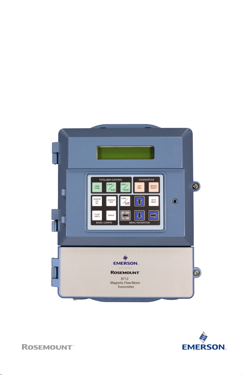
Quick Start Guide
00825-0100-4445, Rev AB
November 2017
Rosemount® 8712EM Transmitter with
HART Protocol
Page 2

Quick Start Guide
1 Safety
WARNING!
• Failure to follow these installation guidelines could result in serious injury
or death.
• Installation and servicing instructions are for use by qualified personnel
only. Do not perform any servicing other than that contained in the
operating instructions, unless qualified.
• Rosemount Magnetic Flowmeters ordered with non-standard paint
options or non-metallic labels may be subject to electrostatic discharge.
To avoid electrostatic charge build-up, do not rub the flowmeter with a
dry cloth or clean with solvents.
• Verify that the operating environment of the sensor and transmitter is
consistent with the appropriate Agency Approval.
• If installed in an explosive atmosphere, verify that the device certification
and installation techniques are suitable for that particular environment.
• To prevent ignition of flammable or combustible atmosphere, disconnect
power before servicing circuits.
• Explosion hazard—Do not disconnect equipment when a flammable or
combustible atmosphere is present.
• Do not connect a Rosemount Transmitter to a non-Rosemount sensor
when installed in an “Ex” environment, explosive atmosphere, hazardous
area, or classified area.
• Follow national, local, and plant standards to properly earth ground the
transmitter and sensor. The earth ground must be separate from the
process reference ground.
November 2017
CAUTION!
• In cases where high voltage/high current are present near the meter
installation, ensure proper protection methods are followed to prevent
stray voltage/current from passing through the meter. Failure to
adequately protect the meter could result in damage to the transmitter
and lead to meter failure.
• Completely remove all electrical connections from both sensor and
transmitter prior to welding on the pipe. For maximum protection of the
sensor, consider removing it from the pipeline.
2 Rosemount 8712EM Transmitter with HART Protocol
Page 3

November 2017
2 Introduction
This document provides basic installation guidelines for the Rosemount
8712EM wall-mount transmitter.
• For sensor installation refer to the Rosemount® 8700 Magnetic Flowmeter
Sensor Quick Installation Guide
• For additional installation information, configuration, maintenance, and
troubleshooting, refer to the Rosemount® 8712EM Transmitter with HART
Protocol Reference Manual
All user documentation can be found at www.emerson.com. For more contact
information see Section 2.2.
2.1 Return policy
Emerson procedures must be followed when returning equipment. These
procedures ensure legal compliance with government transportation
agencies and help provide a safe working environment for Emerson
employees. Failure to follow Emerson procedures will result in your
equipment being refused delivery.
Quick Start Guide
Quick Start Guide 3
Page 4

Quick Start Guide November 2017
2.2 Emerson Flow customer service
Email:
• Worldwide: [email protected]
• Asia-Pacific: [email protected]
Telephone:
North and South America Europe and Middle East Asia Pacific
United States 800 522 6277 U.K. 0870 240 1978 Australia 800 158 727
Canada +1 303 527
Mexico +41 (0) 41 7686
Argentina +54 11 4837
Brazil +55 15 3413
Venezuela +58 26 1731
5200
111
7000
8000
3446
The Netherlands
France 0800 917 901 India 800 440 1468
Germany 0800 182 5347 Pakistan 888 550 2682
Italy 8008 77334 China +86 21 2892
Central & Eastern
Russia/CIS +7 495 981
Egypt 0800 000 0015 Singapore +65 6 777 8211
Oman 800 70101 Thailand 001 800 441
Qatar 431 0044 Malaysia 800 814 008
Kuwait 663 299 01
South Africa 800 991 390
Saudi Arabia 800 844 9564
UAE 800 0444 0684
+31 (0) 704 136
666
+41 (0) 41 7686
111
9811
New Zealand 099 128 804
9000
Japan +81 3 5769
South Korea +82 2 3438
6803
4600
6426
4 Rosemount 8712EM Transmitter with HART Protocol
Page 5

November 2017
3 Pre-installation
Before installing the transmitter, there are several pre-installation steps that
should be completed to make the installation process easier:
• Identify options and configurations that apply to your application
• Set the hardware switches if necessary
• Consider mechanical, electrical, and environmental requirements
Note
Refer to the product reference manual for more detailed requirements.
Identify options and configurations
The typical transmitter installation includes a device power connection, a
4-20mA output connection, and sensor coil and electrode connections.
Other applications may require one or more of the following configurations
or options:
• Pulse output
• Discrete input/discrete output
• HART multidrop configuration
Quick Start Guide
Hardware switches
The transmitter may have up to four user-selectable hardware switches.
These switches set the alarm mode, internal/external analog power, internal/
external pulse power, and transmitter security. The standard configuration
for these switches when shipped from the factory is as follows:
Hardware switch default settingsTable 3-1:
Setting Factory configuration
Alarm mode High
Internal/external analog power Internal
Internal/external pulse power External
Transmitter security Off
The analog power switch and pulse power switches are not available when
ordered with intrinsically safe output, ordering code B.
In most cases, it is not necessary to change the setting of the hardware
switches. If the switch settings need to be changed, refer to the product
reference manual.
Quick Start Guide 5
Page 6

Quick Start Guide November 2017
Be sure to identify any additional options and configurations that apply to the
installation. Keep a list of these options for consideration during the
installation and configuration procedures.
Mechanical considerations
The mounting site for the transmitter should provide enough room for
secure mounting, easy access to conduit entries, full opening of the
transmitter covers, and easy readability of the Local Operator Interface (LOI)
screen (if equipped).
6 Rosemount 8712EM Transmitter with HART Protocol
Page 7
November 2017
Quick Start Guide
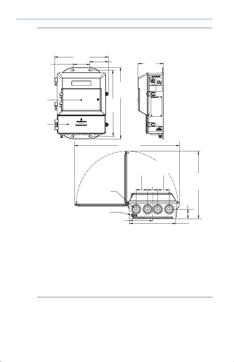
Rosemount 8712EM Dimensional DrawingFigure 3-1:
2.81
[71]
C
D
9.0
[229]
3.12
11.15
[283]
A
B
3.90
[99]
[79]
12.03
[306]
17.68
[449]
1.94
[49]
3.51
[89]
1.70
[43]
1.94
[49]
11.36
[289]
1.59
[40]
7.80
[198]
A. Conduit entry, 1/2-14 NPT (4 places)
B. Ground lug
C. LOI keypad cover
D. Lower cover opens for electrical connections
Note
Dimensions are in inches [Millimeters]
Electrical considerations
Before making any electrical connections to the transmitter, consider
national, local, and plant electrical installation requirements. Be sure to have
Quick Start Guide 7
Page 8

Quick Start Guide
the proper power supply, conduit, and other accessories necessary to comply
with these standards.
The transmitter requires external power. Ensure access to a suitable power
source.
Rosemount 8712EM Flow Transmitter
Power input AC power:
Pulsed circuit Internally powered (Active): Outputs up to
4-20mA output circuit Internally Powered (Active): Outputs up to
Um 250V
Coil excitation output 500mA, 40V max, 9W max
November 2017
Electrical DataTable 3-2:
90–250VAC, 0.45A, 40VA
Standard DC power:
12–42VDC, 1.2A, 15W
Low power DC:
12–30VDC, 0.25A, 3W
12VDC, 12.1mA, 73mW
Externally powered (Passive): Input up to
28VDC, 100mA, 1W
25mA, 24VDC, 600mW
Externally Powered (Passive): Input up to
25mA, 30VDC, 750mW
Environmental considerations
To ensure maximum transmitter life, avoid extreme temperatures and
excessive vibration. Typical problem areas include the following:
• Tropical or desert installations in direct sunlight
• Outdoor installations in arctic climates
Remote mounted transmitters may be installed in the control room to
protect the electronics from the harsh environment and to provide easy
access for configuration or service.
8 Rosemount 8712EM Transmitter with HART Protocol
Page 9
November 2017
4 Mounting
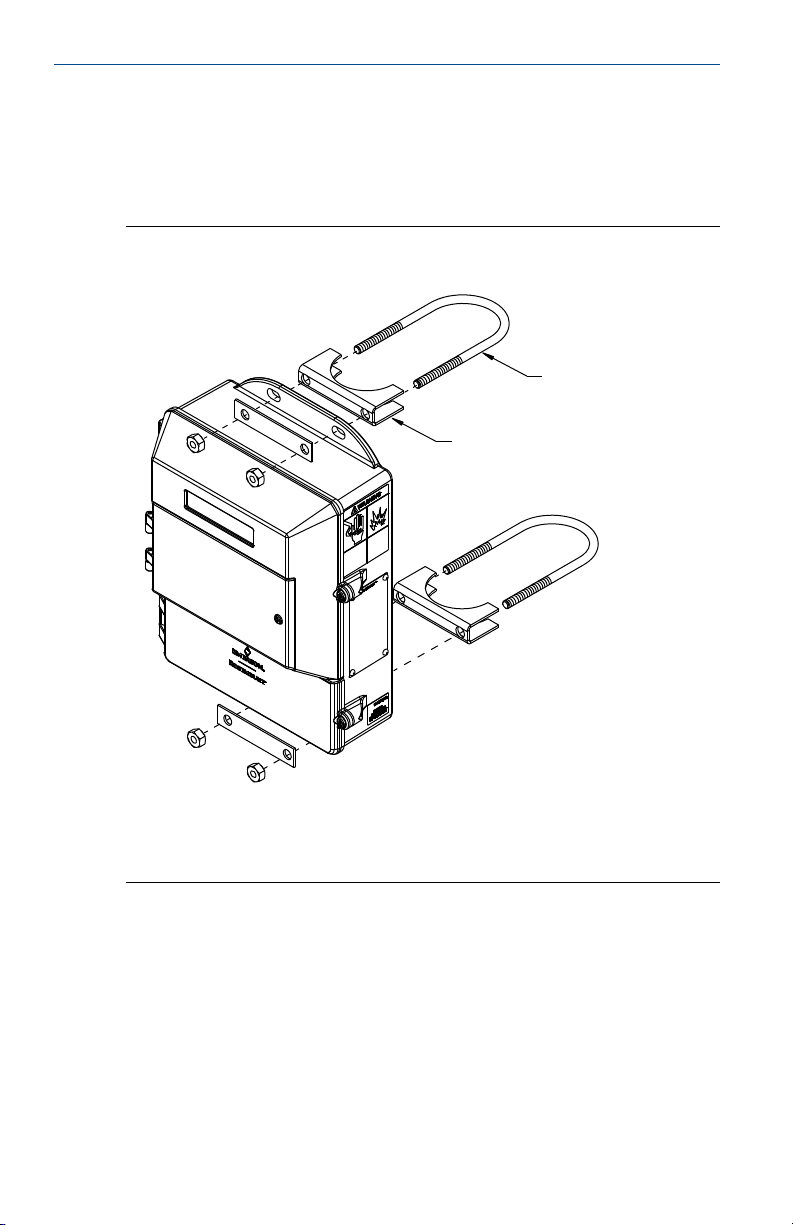
Wall mount transmitters are shipped with mounting hardware for use on a 2in. pipe or flat surface.
Mounting bracketFigure 4-1:
Quick Start Guide
A
B
C
A. U-bolt
B. Saddle clamp
C. Fasteners
4.1
Quick Start Guide 9
Pipe mounting
1. Attach the saddle clamp to the pipe using the U-bolt mounting hardware.
2. Attach the transmitter to the saddle clamp assembly with appropriate
fasteners.
Page 10

Quick Start Guide November 2017
4.2 Surface mounting
Attach the transmitter to the mounting location using customer supplied
mounting screws. The installation of the transmitter shall be rated for four (4)
times the weight of the transmitter or 44lbs ( 20kgs).
10 Rosemount 8712EM Transmitter with HART Protocol
Page 11

November 2017
5 Wiring
5.1 Conduit entries and connections
Transmitter conduit entries ports are ½"-14NPT as standard, M20 conduit
connections will use an adapter. Conduit connections should be made in
accordance with national, local, and plant electrical codes. Unused conduit
entries should be sealed with the appropriate certified plugs. The plastic
shipping plugs do not provide ingress protection.
5.2 Conduit requirements
• For installations with an intrinsically safe electrode circuit, a separate
conduit for the coil cable and the electrode cable may be required. Refer
to the product reference manual.
• For installations with non-intrinsically safe electrode circuit, or when
using the combination cable, a single dedicated conduit run for the coil
drive and electrode cable between the sensor and the remote transmitter
may be acceptable. Removal of the barriers for intrinsic safety isolation is
permitted for non-intrinsically safe electrode installations.
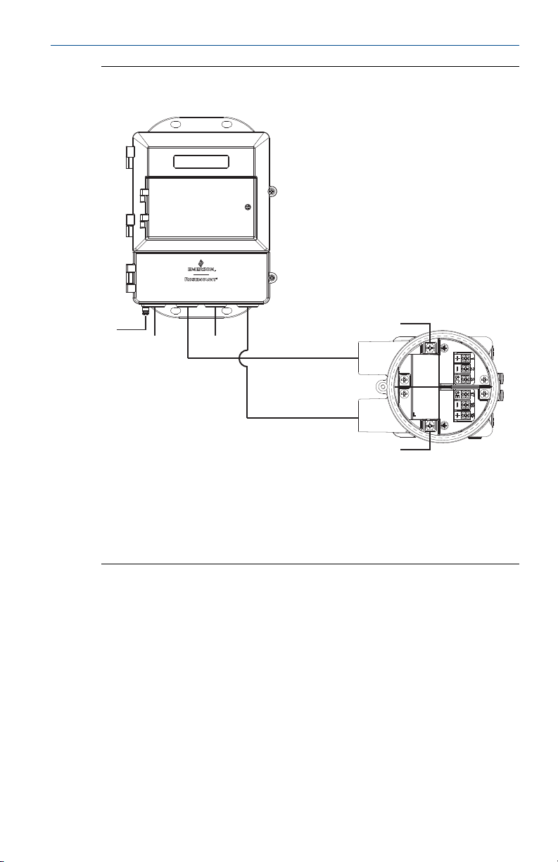
• Bundled cables from other equipment in a single conduit are likely to
create interference and noise in the system. See Figure 5-1.
• Electrode cables should not be run together in the same cable tray with
power cables.
• Output cables should not be run together with power cables.
• Select conduit size appropriate to feed cables through to the flowmeter.
Quick Start Guide
Quick Start Guide 11
Page 12
Quick Start Guide
November 2017
Best practice conduit preparationFigure 5-1:
5.3
A
B
A. Safety ground
B. Power
C. Coil
D. Output
E. Electrode
C D E
A
A
Sensor to transmitter wiring
Wiring details
Cables kits are available as individual component cables or as a combination
coil/electrode cable. Remote cables can be ordered directly using the kit
numbers shown in Table 5-1, Table 5-2, and Table 5-3. Equivalent Alpha cable
part numbers are also provided as an alternative. To order cable, specify
length as quantity desired. Equal length of component cables is required.
Examples:
• 25 feet = Qty (25) 08732-0065-0001
• 25 meters = Qty (25) 08732-0065-0002
12 Rosemount 8712EM Transmitter with HART Protocol
Page 13

November 2017 Quick Start Guide
Component cable kits - standard temperature (-20°C to 75°C)Table 5-1:
Cable kit # Description Individual cable Alpha p/n
08732-0065-0001
(feet)
08732-0065-0002
(meters)
08732-0065-0003
(feet)
08732-0065-0004
(meters)
Kit, component cables, Std temp (includes Coil and Electrode)
Kit, component cables, Std temp (includes Coil and Electrode)
Kit, component cables, Std temp (includes Coil and I.S.
Electrode)
Kit, component cables, Std temp (includes Coil and I.S.
Electrode)
Coil
Electrode
Coil
Electrode
Coil
Instrinsically Safe Blue
Electrode
Coil
Instrinsically Safe Blue
Electrode
2442C
2413C
2442C
2413C
2442C
Not available
2442C
Not available
Table 5-2:
Component cable kits - extended temperature (-50°C to
125°C)
Cable kit # Description Individual cable Alpha p/n
08732-0065-1001
(feet)
08732-0065-1002
(meters)
08732-0065-1003
(feet)
08732-0065-1004
(meters)
Table 5-3:
Combination cable kits - coil and electrode cable (-20°C to
Kit, Component Cables, Ext Temp. (includes Coil and Electrode)
Kit, Component Cables, Ext Temp. (includes Coil and Electrode)
Kit, Component Cables, Ext Temp. (includes Coil and I.S.
Electrode)
Kit, Component Cables, Ext Temp. (includes Coil and I.S.
Electrode)
Coil
Electrode
Coil
Electrode
Coil
Intrinsically Safe Blue
Electrode
Coil
Intrinsically Safe Blue
Electrode
Not available
Not available
Not available
Not available
Not available
Not available
Not available
Not available
80°C)
Cable kit # Description
08732-0065-2001 (feet) Kit, Combination Cable, Standard
08732-0065-2002 (meters)
08732-0065-3001 (feet) Kit, Combination Cable, Submersible
08732-0065-3002 (meters)
(80°C dry/60°C Wet)
(33ft Continuous)
Quick Start Guide 13
Page 14

Quick Start Guide November 2017
Cable requirements
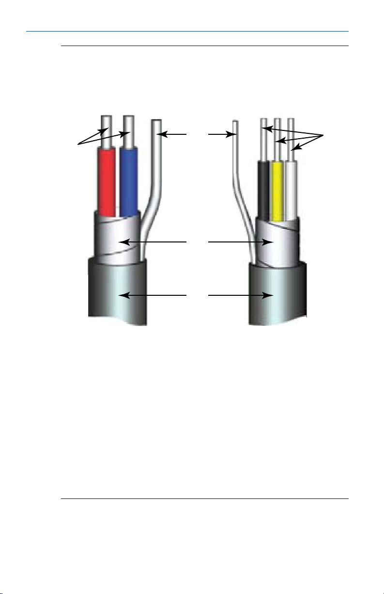
Shielded twisted pairs or triads must be used. For installations using the
individual coil drive and electrode cable, see Figure 5-2. Cable lengths should
be limited to less than 500 feet (152 m). Consult factory for length between
500–1000 feet (152–304 m). Equal length cable is required for each. For
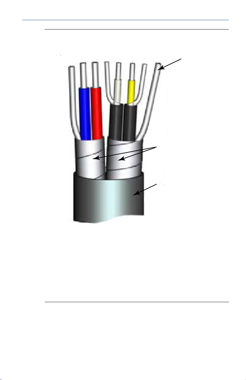
installations using the combination coil drive/electrode cable, see Figure 5-3.
Combination cable lengths should be limited to less than 330 feet (100 m).
14 Rosemount 8712EM Transmitter with HART Protocol
Page 15
November 2017
Quick Start Guide
Individual component cablesFigure 5-2:
A B
1 2
3
3
D
C
E
F
A. Coil drive
B. Electrode
C. Twisted, stranded, insulated 14 AWG conductors
D. Drain
E. Overlapping foil shield
F. Outer jacket
G. Twisted, stranded, insulated 20 AWG conductors
• 1 = Red
• 2 = Blue
• 3 = Drain
• 17 = Black
• 18 = Yellow
• 19 = White
17 18 19
G
Quick Start Guide 15
Page 16
Quick Start Guide
November 2017
Combination coil and electrode cableFigure 5-3:
17
1
2
3
19
18
17
A
B
C
A. Electrode shield drain
B. Overlapping foil shield
C. Outer jacket
• 1 = Red
• 2 = Blue
• 3 = Drain
• 17 = Reference
• 18 = Yellow
• 19 = White
Cable preparation
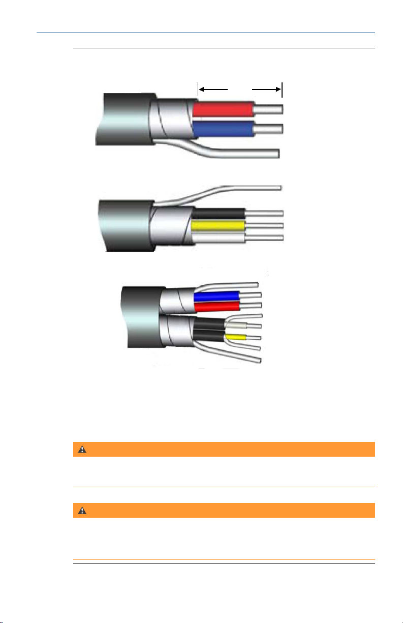
Prepare the ends of the coil drive and electrode cables as shown in Figure 5-4.
Remove only enough insulation so that the exposed conductor fits
completely under the terminal connection. Best practice is to limit the
unshielded length (D) of each conductor to less than one inch. Excessive
16 Rosemount 8712EM Transmitter with HART Protocol
Page 17

November 2017 Quick Start Guide
removal of insulation may result in an unwanted electrical short to the
transmitter housing or other terminal connections. Excessive unshielded
length, or failure to connect cable shields properly, may also expose the unit
to electrical noise, resulting in an unstable meter reading.
Quick Start Guide 17
Page 18
Quick Start Guide
A
B
November 2017
Cable endsFigure 5-4:
D
C
A. Coil
B. Electrode
C. Combination
D. Unshielded length
WARNING!
Shock hazard! Potential shock hazard across remote junction box terminals 1 and
2 (40V).
WARNING!
Explosion hazard! Electrodes exposed to process. Use only compatible transmitter
and approved installation practices. For process temperatures greater than 284°F
(140°C), use a wire rated for 257°F (125°C).
18 Rosemount 8712EM Transmitter with HART Protocol
Page 19
November 2017
Remote junction box terminal blocks
Quick Start Guide
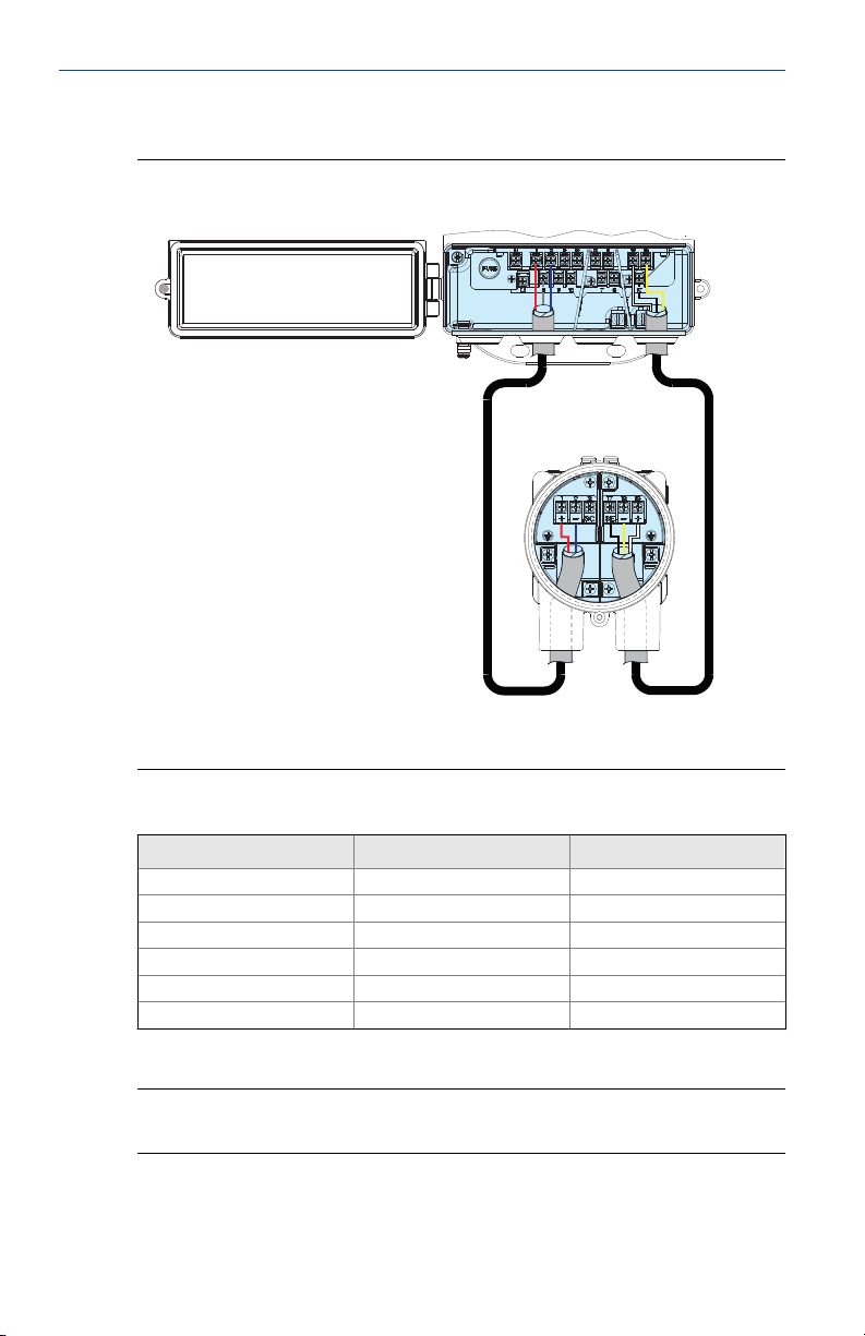
Remote junction box viewsFigure 5-5:
B
A
A. Sensor
B. Transmitter
Sensor/transmitter wiringTable 5-4:
Wire color Sensor terminal Transmitter terminal
Red 1 1
Blue 2 2
Shield 3 or Float 3
Black 17 17
Yellow 18 18
White 19 19
Note
For hazardous locations, refer to the product reference manual.
Quick Start Guide 19
Page 20
Quick Start Guide November 2017
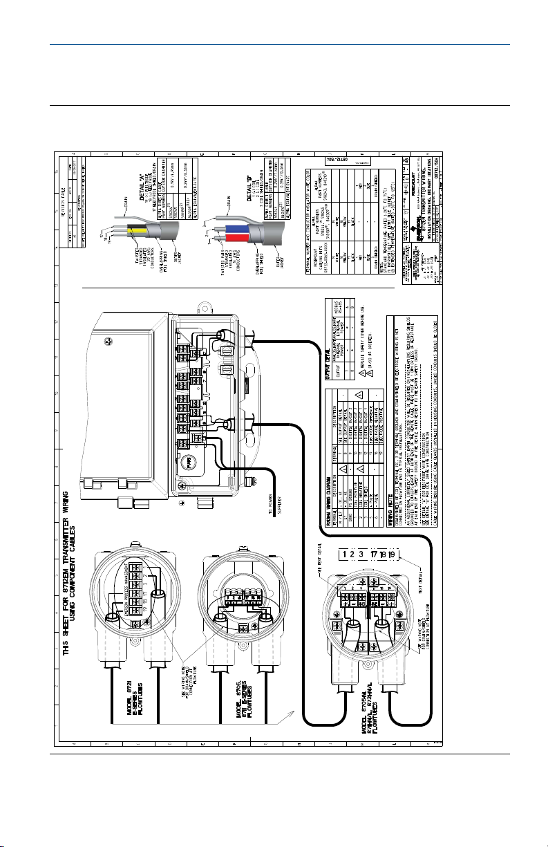
5.4 Wiring diagrams
Wiring 8712EM using component cableFigure 5-6:
20 Rosemount 8712EM Transmitter with HART Protocol
Page 21
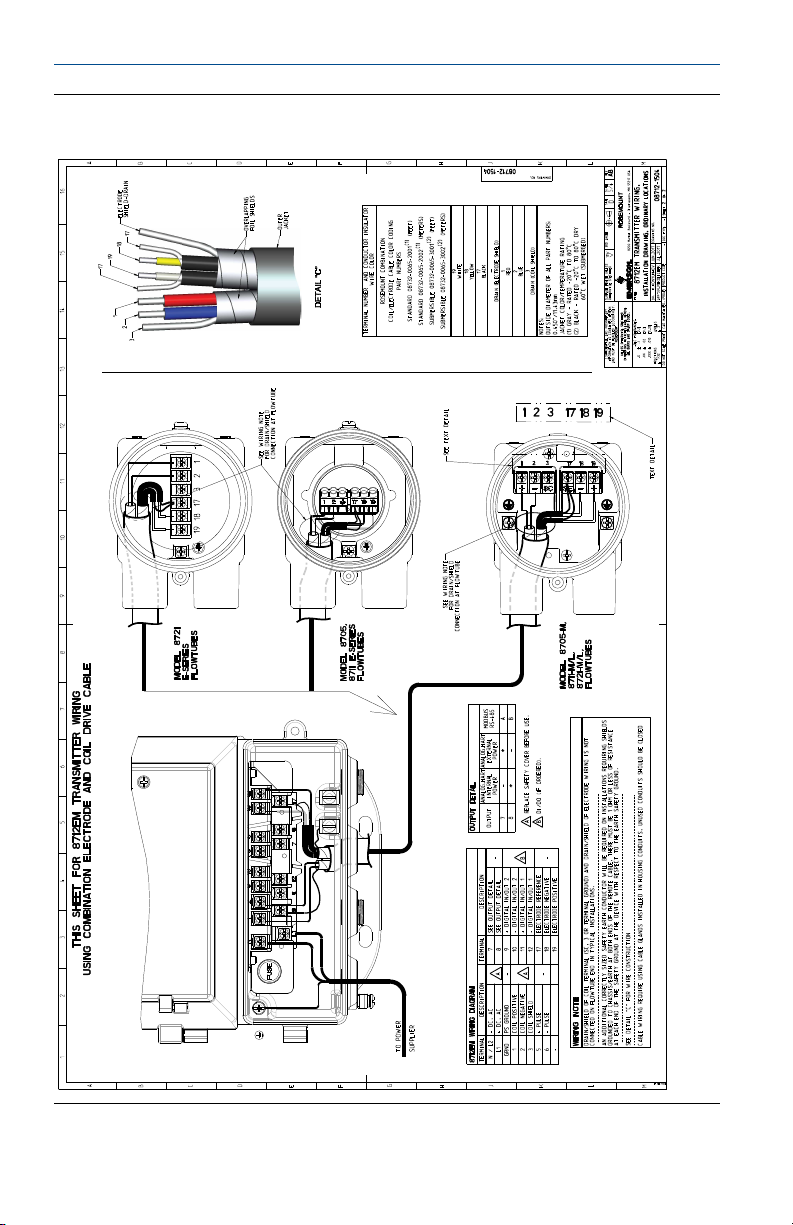
November 2017 Quick Start Guide
Wiring 8712EM using combination cableFigure 5-7:
Quick Start Guide 21
Page 22
Quick Start Guide
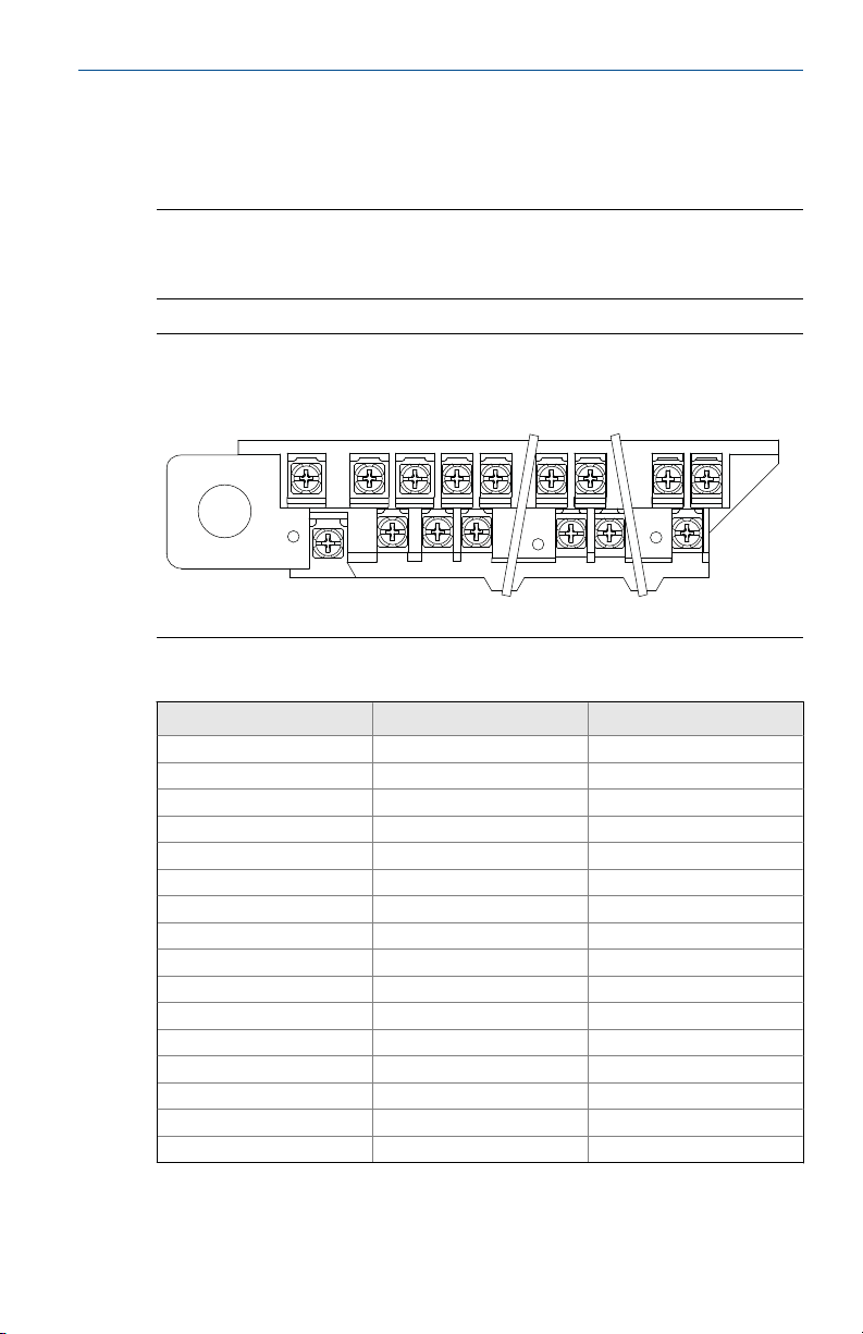
5.5 Power and I/O terminal blocks
Open the bottom cover of the transmitter to access the terminal block.
Note
To connect pulse output and/or discrete input/output, and for installations
with intrinsically safe outputs, refer to the product reference manual.
8712EM Terminal blocksFigure 5-8:
N 1 2 9 10 5 6 19 18
L1 3 11 12 7 8 17
November 2017
8712EM Power and I/O terminalsTable 5-5:
Terminal number AC version DC version
1 Coil Positive Coil Positive
2 Coil Negative Coil Negative
3 Coil Shield Coil Shield
5 + Pulse + Pulse
6 – Pulse – Pulse
(1)
7
(1)
8
(2)
9
(2)
10
(2)
11
(2)
12
17 Electrode Reference Electrode Reference
18 Electrode Negative Electrode Negative
19 Electrode Positive Electrode Positive
N AC (Neutral)/L2 DC (–)
L1 AC L1 DC (+)
(1) Note Polarity: Internally Powered, Terminal 7 (–) Analog HART, Terminal 8 (+) Analog HART.
Externally Powered, Terminal 7 (+) Analog HART, Terminal 8 (–) Analog HART
(2) Only available with ordering code AX.
22 Rosemount 8712EM Transmitter with HART Protocol
Analog HART Analog HART
Analog HART Analog HART
+ Discrete In/Out 2 + Discrete In/Out 2
– Discrete In/Out 2 – Discrete In/Out 2
+ Discrete In/Out 1 + Discrete In/Out 1
– Discrete In/Out 1 – Discrete In/Out 1
Page 23
November 2017
5.6 Powering the transmitter
The transmitter is available in three models. The AC powered transmitter is
designed to be powered by 90–250VAC (50/60Hz). The DC powered
transmitter is designed to be powered by 12–42VDC. The low power
transmitter is designed to be powered by 12–30VDC. Before connecting
power to the transmitter, be sure to have the proper power supply, conduit,
and other accessories. Wire the transmitter according to national, local, and
plant electrical requirements for the supply voltage.
If installing in a hazardous location, verify that the meter has the appropriate
hazardous area approval. Each meter has a hazardous area approval tag
attached to the side of the transmitter housing.
AC power supply requirements
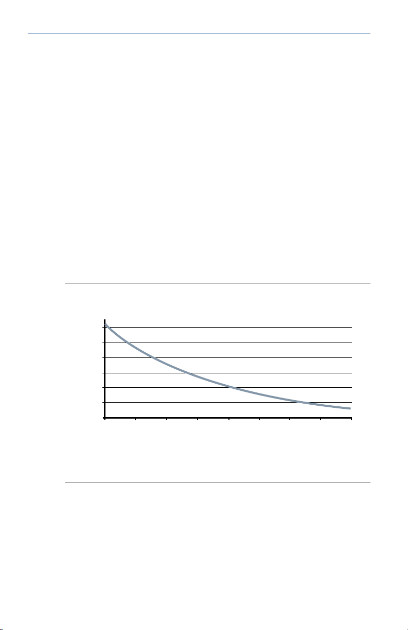
Units powered by 90 - 250VAC have the following power requirements. Peak
inrush is 35.7A at 250VAC supply, lasting approximately 1ms. Inrush for other
supply voltages can be estimated with: Inrush (Amps) = Supply (Volts) / 7.0
AC current requirementsFigure 5-9:
Quick Start Guide
0.24
0.22
0.20
A
0.18
0.16
0.14
0.12
90
110 130 150 170B190 210 230 250
A. Supply current (amps)
B. Power supply (VAC)
Quick Start Guide 23
Page 24
Quick Start Guide
A
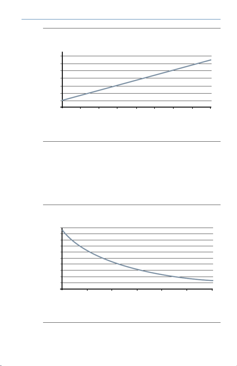
A. Apparent power (VA)
B. Power supply (VAC)
DC power supply requirements
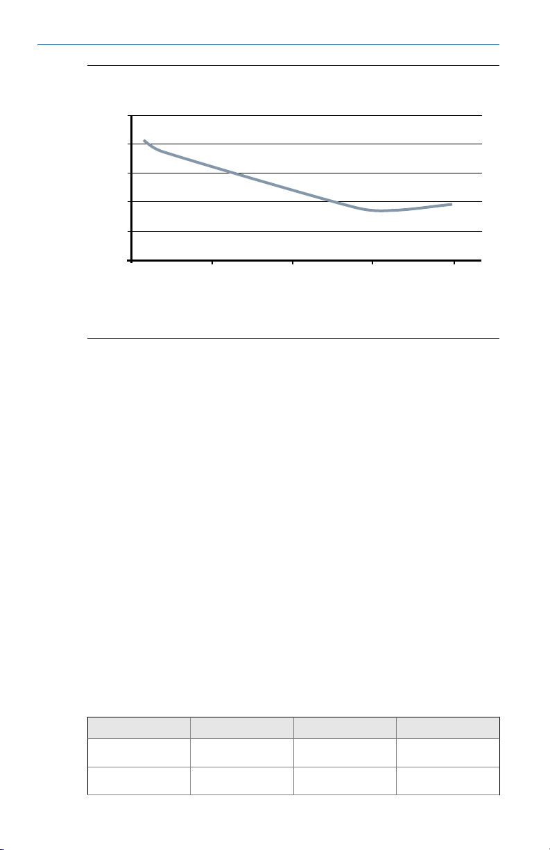
Standard DC units powered by 12VDC power supply may draw up to 1.2A of
current steady state. Low power DC units may draw up to 0.25A of current
steady state. Peak inrush is 42A at 42VDC supply, lasting approximately 1ms.
Inrush for other supply voltages can be estimated with: Inrush (Amps) =
Supply (Volts) / 1.0
34
32
30
28
26
24
22
20
Apparent powerFigure 5-10:
90
110 130 150 170B190 210 230 250
November 2017
DC current requirementsFigure 5-11:
1.2
1.1
1.0
0.9
0.8
A
0.7
0.6
0.5
0.4
0.3
0.2
12
17 22 27
B
32 37 42
A. Supply current (amps)
B. Power supply (VDC)
24 Rosemount 8712EM Transmitter with HART Protocol
Page 25
November 2017 Quick Start Guide
Low power DC current requirementsFigure 5-12:
0.25
0.2
0.15
A
0.1
0.05
0
10
15 20 25
B
30
A. Supply current (amps)
B. Power supply (VDC)
Supply wire requirements
Use 10–18 AWG wire rated for the proper temperature of the application. For
wire 10–14 AWG use lugs or other appropriate connectors. For connections
in ambient temperatures above 122 °F (50 °C), use a wire rated for 194 °F
(90 °C). For DC powered transmitters with extended cable lengths, verify that
there is a minimum of 12VDC at the terminals of the transmitter with the
device under load.
Electrical disconnect requirements
Connect the device through an external disconnect or circuit breaker per
national and local electrical code.
Installation category
The installation category for the transmitter is OVERVOLTAGE CAT II.
Overcurrent protection
The transmitter requires overcurrent protection of the supply lines. Fuse
rating and compatible fuses are shown in Table 5-6.
Fuse requirementsTable 5-6:
Power system Power supply Fuse rating Manufacturer
AC power 90–250VAC 2 Amp quick acting Bussman AGC2 or
DC power 12–42VDC 3 Amp quick acting Bussman AGC3 or
Quick Start Guide 25
equivalent
equivalent
Page 26

Quick Start Guide
Power system Power supply Fuse rating Manufacturer
DC low power 12–30VDC 3 Amp quick acting Bussman AGC3 or
Power terminals
For AC powered transmitter (90–250VAC, 50/60 Hz):
• Connect AC Neutral to Terminal N and AC Line to Terminal L1.
For DC powered transmitter:
• Connect negative to Terminal N and positive to Terminal L1.
• DC powered units may draw up to 1.2A.
Covers
Use the transmitter lower door screw to secure the terminal compartment
after the instrument has been wired and powered up. Follow these steps to
ensure the housing is properly sealed to meet ingress protection
requirements:
1. Ensure all wiring is complete and close the lower door.
2. Tighten the lower door screw until the lower door is tight against the
housing. Metal to metal contact of the screw bosses is required to ensure
a proper seal.
November 2017
Fuse requirements (continued)Table 5-6:
equivalent
Note
Application of excessive torque may strip the threads or break the screw.
3. Verify the lower door is secure.
5.7
Analog output
The analog output signal is a 4-20mA current loop. Depending on the IS
output option, the loop can be powered internally or externally via a
hardware switch located on the front of the electronics stack. The switch is
set to internal power when shipped from the factory. Intrinsically safe analog
output requires a shielded twisted pair cable. For HART communication, a
minimum resistance of 250 ohms is required. It is recommended to use
individually shielded twisted pair cable. The minimum conductor size is 24
AWG (0.51mm) diameter for cable runs less than 5,000 feet (1,500m) and 20
AWG (0.81mm) diameter for longer distances.
26 Rosemount 8712EM Transmitter with HART Protocol
Page 27
November 2017
Note
For more information about the analog output characteristics, refer to the
product reference manual.
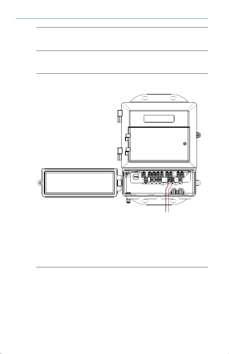
Internal Power
Quick Start Guide
Analog output wiring, internal powerFigure 5-13:
A B
A. 4–20 mA (–) to Terminal #7
B. 4–20 mA (+) to Terminal #8
Note
Terminal polarity for the analog output is reversed between internally and
externally powered.
Quick Start Guide 27
Page 28
Quick Start Guide
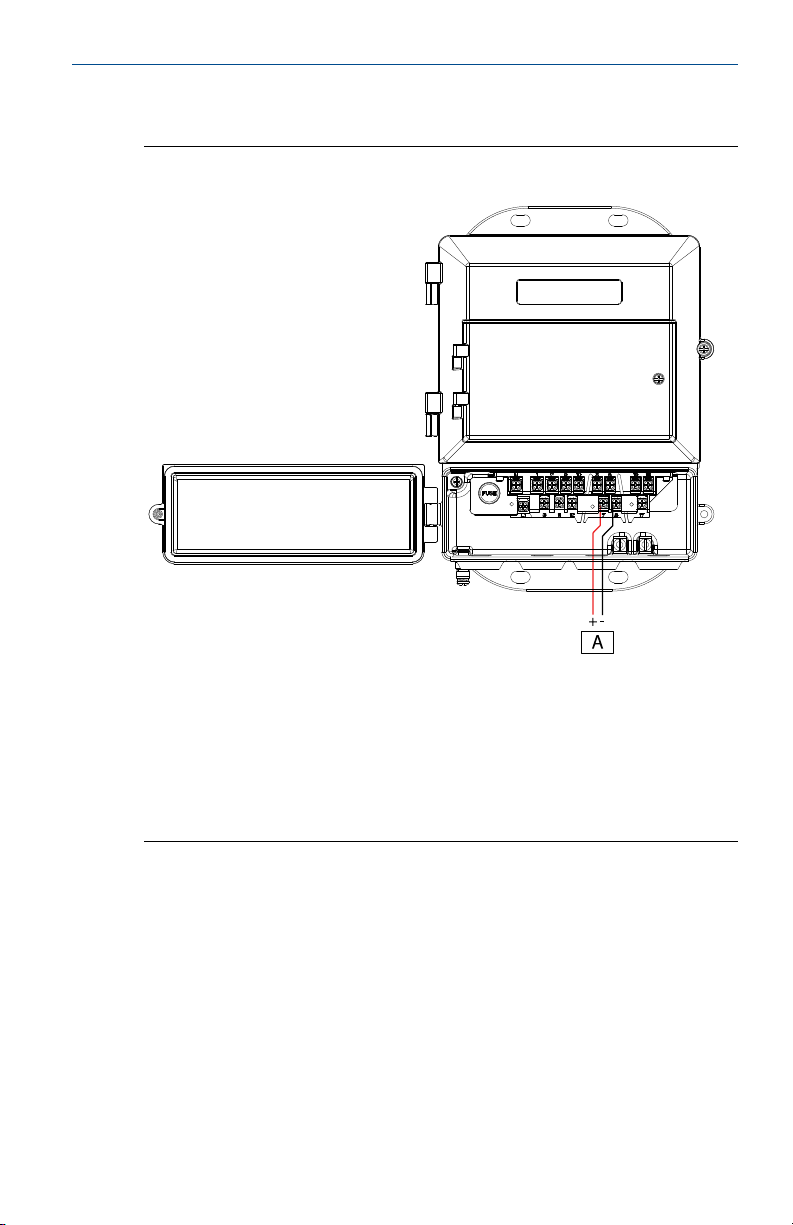
External power
November 2017
Analog output wiring, external powerFigure 5-14:
A. Power supply
• (+) to Terminal #7
• (–) to Terminal #8
Note
Terminal polarity for the analog output is reversed between internally and
externally powered.
28 Rosemount 8712EM Transmitter with HART Protocol
Page 29

November 2017
A. Load (ohms)
B. Power supply (volts)
C. Operating region
• R
• Vps = power supply voltage (volts)
• Rmax = maximum loop resistance (ohms)
Analog loop load limitationsFigure 5-15:
600
A
0
= 31.25 (Vps–10.8)
max
Quick Start Guide
C
10.8 30
B
Quick Start Guide 29
Page 30

Quick Start Guide
6 Basic Configuration
Once the magnetic flowmeter is installed and power has been supplied, the
transmitter must be configured through the basic setup. These parameters
can be configured through either an LOI or a HART communication device.
Configuration settings are saved in nonvolatile memory within the
transmitter. Descriptions of more advanced functions are included in the
product reference manual.
6.1 Basic Setup
Tag
Tag is the quickest and shortest way of identifying and distinguishing
between transmitters. Transmitters can be tagged according to the
requirements of your application. The tag may be up to eight characters long
as standard, or 32 characters long when ordered with HART 7.
Flow units (PV)
The flow units variable specifies the format in which the flow rate will be
displayed. Units should be selected to meet your particular metering needs. .
Line size
November 2017
The line size (sensor size) must be set to match the actual sensor connected
to the transmitter. The size must be specified in inches.
Upper range value (URV)
The URV sets the 20 mA point for the analog output. This value is typically set
to full-scale flow. The units that appear will be the same as those selected
under the flow units parameter. The URV may be set between –39.3 ft/s to
39.3 ft/s (–12 m/s to 12m/s). There must be at least 1 ft/s (0.3 m/s) span
between the URV and LRV.
Lower range value (LRV)
The LRV sets the 4 mA point for the analog output. This value is typically set
to zero flow. The units that appear will be the same as those selected under
the flow units parameter. The LRV may be set between –39.3 ft/s to 39.3 ft/s
(–12 m/s to 12m/s). There must be at least 1 ft/s (0.3 m/s) span between the
URV and LRV.
30 Rosemount 8712EM Transmitter with HART Protocol
Page 31

November 2017 Quick Start Guide
Calibration number
The sensor calibration number is a 16-digit number generated at the factory
during flow calibration, is unique to each sensor, and is located on the sensor
tag.
6.2 Local operator interface (LOI)
To access the transmitter menu, press the XMTR MENU key. Use the UP,
DOWN, LEFT(E), and RIGHT arrows to navigate the menu structure. A
complete map of the LOI menu structure is shown in the product reference
manual.
The display can be locked to prevent unintentional configuration changes.
The display lock can be activated through a HART communication device, or
by holding the UP arrow for three seconds and then following the on-screen
instructions.
When the display lock is activated, a lock symbol will appear in the lower
right hand corner of the display. To deactivate the display lock, hold the UP
arrow for three seconds and follow the on-screen instructions. Once
deactivated, the lock symbol will no longer appear in the lower right hand
corner of the display.
6.3
Field Communicator interface
Use the menu paths to configure basic setup of the transmitter using a field
communicator.
Basic setup menu pathsTable 6-1:
Function Menu path
Basic Setup Configure > Manual Setup > Basic Setup
Flow Units Configure > Manual Setup > Basic Setup > Flow Units
PV Upper Range Value (URV) Configure > Manual Setup > Basic Setup > AO > URV
PV Lower Range Value (LRV) Configure > Manual Setup > Basic Setup > AO > LRV
Calibration Number Configure > Manual Setup > Basic Setup > Setup > Calibration
Line Size Configure > Manual Setup > Basic Setup > Setup > Line Size
Tag Configure > Manual Setup > Device Info > Identification > Tag
Long Tag Configure > Manual Setup > Device Info > Identification > Long
Overview Overview
Quick Start Guide 31
number
Tag
Page 32

*00825-0100-4445*
Emerson Automation Solutions USA
7070 Winchester Circle
Boulder, Colorado USA 80301
T +1 303-527-5200
T +1 800-522-6277
F +1 303-530-8459
www.emerson.com
Emerson Automation Solutions Europe
Neonstraat 1
6718 WX Ede
The Netherlands
T +31 (0) 70 413 6666
F +31 (0) 318 495 556
www.micromotion.nl
Quick Start Guide
00825-0100-4445, rev. AB
November 2017
Emerson Automation Solutions Asia
1 Pandan Crescent
Singapore 128461
Republic of Singapore
T +65 6777-8211
F +65 6770-8003
Emerson Automation Solutions Japan
1-2-5, Higashi Shinagawa
Shinagawa-ku
Tokyo 140-0002 Japan
T +81 3 5769-6803
F +81 3 5769-6844
Emerson Automation Solutions United Kingdom
Emerson Process Management Limited
Horsfield Way
Bredbury Industrial Estate
Stockport SK6 2SU U.K.
T +44 0870 240 1978
F +44 0800 966 181
©
2017 Rosemount, Inc. All rights reserved.
The Emerson logo is a trademark and service mark
of Emerson Electric Co. Rosemount, 8600, 8700,
8800 marks are marks of one of the Emerson
Automation Solutions family of companies. All
other marks are property of their respective
owners.
 Loading...