

Page 1

Quick Start Guide
00825-0100-4697, Rev SF
June 2016
Rosemount™ 848T FOUNDATION™ Fieldbus
High Density Temperature Transmitter
Device Revision 8 - Requires New DD/CFF Revision
Page 2
Quick Start Guide
June 2016
NOTICE
This guide provides basic guidelines for the Rosemount 848T. It does not provide instructions for detailed
configuration, diagnostics, maintenance, service, troubleshooting. Refer to the Rosemount 848T Reference
Manual (document number 00809-0100-4697) for more instruction. The manual and this guide are also
available electronically on www.rosemount.com.
Explosions could result in death or serious injury.
Installation of this transmitter in an explosive environment must be in accordance with the appropriate
local, national, and international standards, codes, and practices. Review the approvals section of this
manual for any restrictions associated with a safe installation.
Process leaks may cause harm or result in death.
Install and tighten thermowells or sensors before applying pressure.
Do not remove the thermowell while in operation.
Electrical shock can result in death or serious injury.
Avoid contact with the leads and terminals. High voltage that may be present on leads can cause electrical
shock.
Shipping considerations for wireless products:
The unit was shipped to you without the power module installed. Remove the power module prior to
shipping the unit.
Each power module contains two “C” size primary lithium batteries. Primary lithium batteries are regulated
in transportation by the U.S. Department of Transportation, and are also covered by IATA (International Air
Transport Association), ICAO (International Civil Aviation Organization), and ARD (European Ground
Transportation of Dangerous Goods). It is the responsibility of the shipper to ensure compliance with these
or any other local requirements. Consult current regulations and requirements before shipping.
Contents
Mount the transmitter. . . . . . . . . . . . . . . . . . . . . 3
Wire and apply power . . . . . . . . . . . . . . . . . . . . . 5
Verify the tag. . . . . . . . . . . . . . . . . . . . . . . . . . . . 10
2
Verify the transmitter configuration . . . . . . . 10
Product Certifications. . . . . . . . . . . . . . . . . . . . 13
Page 3
June 2016
Step 1: Mount the transmitter
Mount to a DIN rail without a junction box
1. Pull up the DIN rail mounting clip located on the top back side of the
transmitter.
2. Hinge the DIN rail into the slots on the bottom of the transmitter.
3. Tilt the Rosemount 848T and place onto the DIN rail.
4. Release the mounting clip.
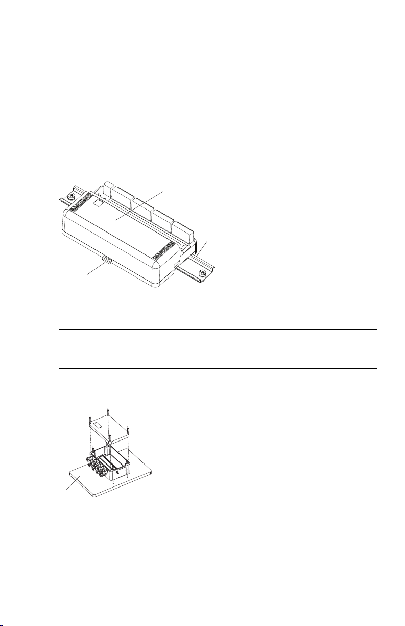
Figure 1. Mounting the Rosemount 848T to a DIN Rail
A
B
C
A. Rosemount 848T without installed enclosure
B. DIN Rail
C. DIN Rail mounting clip
Quick Start Guide
Mounting to a panel with a junction box
Figure 2. Aluminum/Plastic Junction Box
A
B
C
A. Aluminum or plastic junction box
B. Mounting screws (4)
C. Panel
1. Mount using four 1/4-20 ⫻ 1.25-in. screws.
(1)
3
Page 4

Quick Start Guide
5.1
(130)
10.2
(260)
6.6
(167)
(1)
4.7 (114)
7.5 (190)
(1)
Figure 3. Stainless Steel Junction Box
A
B
C
A. Stainless steel junction box
B. Mounting screws (2)
C. Panel
(1)
Mounting to a 2-in. pipe stand
Use the optional mounting bracket (option code B6) to attach the 848T to a 2-in.
pipe stand when using a junction box.
June 2016
Figure 4. Aluminum/Plastic Junction Box
Fron t view Side view
Figure 5. Stainless Steel Junction Box
Fron t view Side view
(2)
(2)
1. Mount using two 1/4–20 1/2-in. screws.
2. Fully assembled.
4
Page 5

June 2016
Quick Start Guide
Figure 6. Mounted on a Vertical Pipe
Aluminum/plastic junction box Stainless steel junction box
Step 2: Wire and apply power
Power is polarity insensitive, allowing the user to connect positive (+) or negative
OUNDATION Fieldbus wires to either FOUNDATION Fieldbus wiring terminal on
(–) F
the terminal block.
Using cable glands
1. Remove the four cover screws to remove the junction box cover.
2. Run the sensor and power/signal wires through the appropriate pre-installed
cable glands.
3. Install the sensor wires into the correct screw terminals.
4. Attach the F
5. Replace the F
OUNDATION Fieldbus wires to the screw terminals.
OUNDATION Fieldbus cover and tighten all cover screws.
Using conduit entries
1. Unscrew the four cover screws to remove the junction box cover.
2. Remove the five conduit plugs and install the user-supplied conduit fittings.
3. Run pairs of sensor wires through each conduit fitting.
4. Install the sensor wires into the correct screw terminals.
5. Attach the F
6. Replace the enclosure cover and tighten all cover screws.
OUNDATION Fieldbus wires to the screw terminals.
5
Page 6
Quick Start Guide
A
C
E
G
I
J
B
D
F
H
11 1 1222 23333
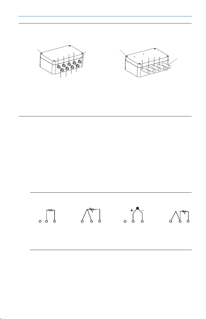
Figure 7. Wiring Connections
Cable gland Conduit entries
June 2016
F
D
C
B
A
E
A. Sensor 1
B. Sensor 2
C. Sensor 3
D. Sensor 4
E. Sensor 5
F. S en sor 6
G. Sensor 7
H. Sensor 8
I. Power/signal
J. Cover screw
A. Sensor 1 and 2
B. Sensor 3 and 4
C. Sensor 5 and 6
D. Sensor 7 and 8
E. Power/signal
F. Cover screw
Sensor wiring and power supply
Compatible with eight independently configurable channels including
combinations of 2- and 3-wire RTDs, thermocouples, mV, ohm and mA
sensors.
All sensor and power terminals are rated to 42.4 Vdc.
FOUNDATION fieldbus network powered with a terminal voltage of 9.0 to 32.0
Vdc and 22 mA maximum current draw.
For best network performance twisted, shielded pair cabling should be used.
Proper gage wire should be selected to maintain the 9.0 Vdc minimum.
Figure 8. Sensor Wiring Diagrams
Thermocouples/
2-wire RTD and Ohms 3-wire RTD and Ohms
1. Emerson™ Process Management provides 4-wire sensors for all single-element RTDs. Use these RTDs in 3-wire
configurations by clipping the fourth lead or leaving it disconnected and insulated with electrical tape.
2.The transmitter must be configured for a 3-wire RTD in order to recognize an RTD with a compensation loop.
(1)
Ohms and millivolts
2-Wire RTD with
compensation loop
The wiring of 3-wire RTDs for this unit is different than some earlier Rosemount
848T models. Pay careful attention to the wiring diagram on the label, especially
if this unit is replacing an older unit.
6
(2)
Page 7
June 2016
A
BC
D
EE
F
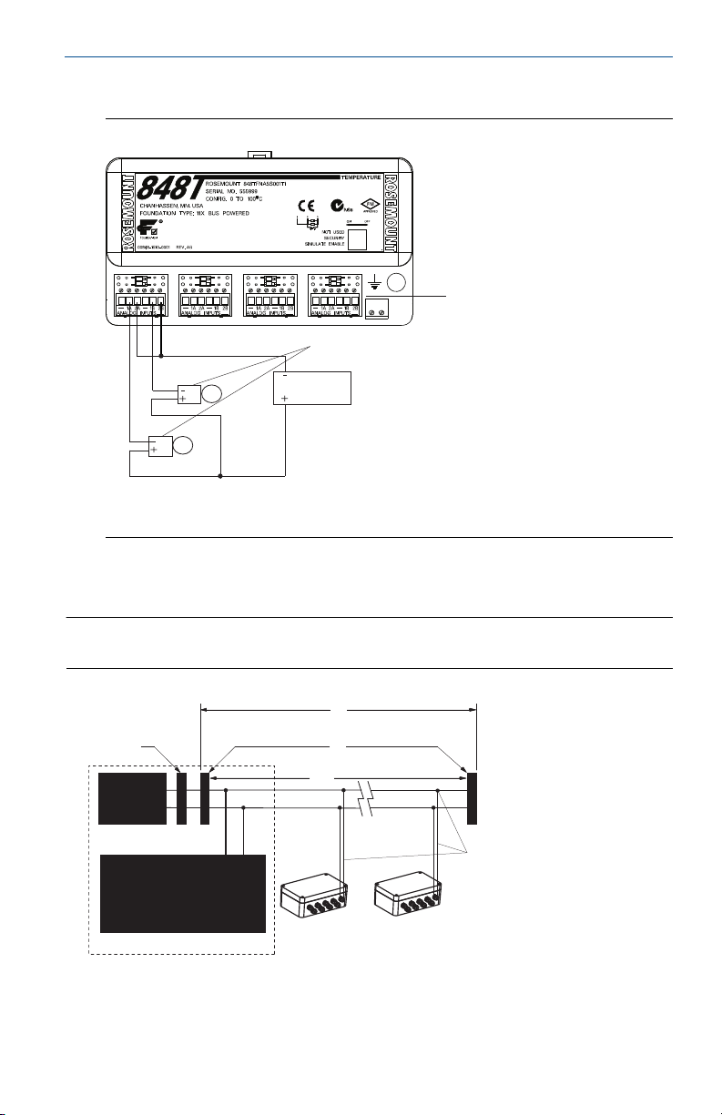
Wiring analog inputs
Figure 9. Rosemount 848T Analog Input Wiring Diagram
B
C
A. Analog input connectors
B. Analog transmitters
C. Power supply
Quick Start Guide
A
Typical configuration for FOUNDATION Fieldbus networking
Note
Each segment in a FOUNDATION Fieldbus trunk must be terminated at both ends.
A. 6234 ft. (1900 m) max
(depending upon cable characteristics)
B. Integrated power conditioner and filter
C. Terminators
D. Trunk
E. Spur
F. Sig na l w iring
7
Page 8
Quick Start Guide
A
B
C
D
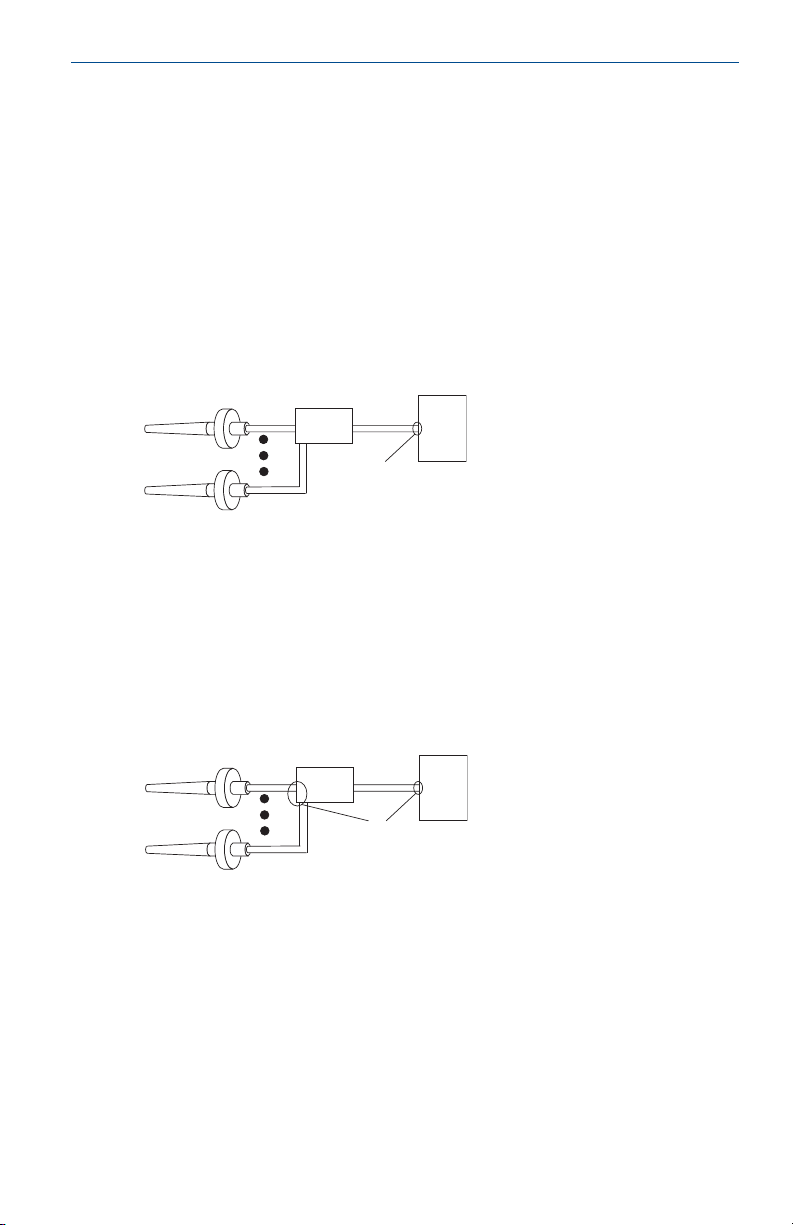
Ground the transmitter
Proper ground is crucial to reliable temperature readings.
Ungrounded thermocouple, mV, and RTD/Ohm inputs
Option 1
1. Connect FOUNDATION Fieldbus signal wiring shield to the sensor wiring
shield(s).
2. Ensure the shields are tied together and electrically isolated from the
transmitter enclosure.
3. Only ground the shield at the power supply end.
4. Ensure that the sensor shield(s) is electrically isolated from the surrounding
grounded fixtures.
June 2016
A
A. Sensor wires
B. Rosemount 848T
B
D
C. Power supply
D. Shield ground point
C
Option 2
1. Connect sensor wiring shield(s) to the transmitter enclosure (only if the
enclosure is grounded).
2. Ensure the sensor shield(s) is electrically isolated from surrounding fixtures
that may be grounded.
3. Ground F
A. Sensor wires
B. Rosemount 848T
OUNDATION Fieldbus signal wiring shield at the power supply end.
C. Power supply
D. Shield ground point
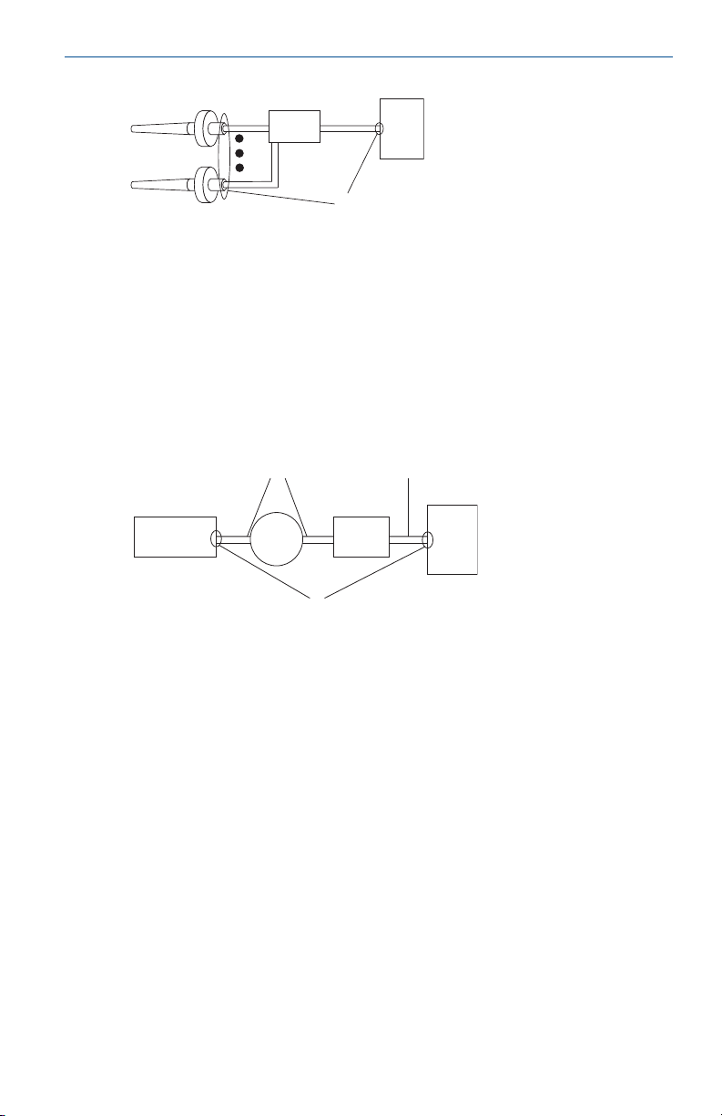
Grounded thermocouple inputs
1. Ground sensor wiring shield(s) at the sensor.
2. Ensure the sensor wiring and F
electrically isolated from the transmitter enclosure.
3. Do not connect the F
OUNDATION Fieldbus signal wiring shield to the sensor
wiring shield(s).
OUNDATION Fieldbus signal wiring shields are
8
Page 9
June 2016
A
B
C
D
4. Ground FOUNDATION Fieldbus signal wiring shield at the power supply end.
Quick Start Guide
A. Sensor wires
B. Rosemount 848T
C. Power supply
D. Shield ground point
Analog device inputs
1. Ground analog signal wire at the power supply of the analog devices.
2. Ensure the analog signal wire and the F
are electrically isolated from the transmitter enclosure.
3. Do not connect the analog signal wire shield to the F
wire shield.
4. Ground F
OUNDATION Fieldbus signal wire shield at the power supply end.
B
A
CD
G
A. Analog device power supply
B. 4-20 mA loop
C. Analog device
D. Rosemount 848T
Transmitter enclosure (optional)
Ground in accordance with local electrical requirements.
OUNDATION Fieldbus signal wire shields
OUNDATION Fieldbus signal
E
F
E. FOUNDATION Fieldbus
F. Power supply
G. Shield ground points
9
Page 10

Quick Start Guide
Step 3: Verify the tag
The 848T has a removable commissioning tag that
contains both the Device ID (the unique code that
identifies a particular device in the absence of a device
tag) and a space to record the device tag (the
operational identification for the device as defined by
the Piping and Instrumentation Diagram [P&ID]).
When commissioning more than one device on a
Foundation fieldbus segment, it can be difficult to
identify which device is at a particular location. The
removable tag aids in this process by linking the Device
ID to physical location. The installer should note the
physical location of the transmitter on both the upper
and lower location of the commissioning tag. The
bottom portion should be torn off for each device on the
segment and used for commissioning the segment in
the control system.
Step 4: Verify the transmitter configuration
Each FOUNDATION Fieldbus host or configuration tool has a different way of
displaying and performing configurations. Some use Device Descriptions (DD) or
DD wizards for configuration and to display data consistently across platforms.
There is no requirement that a host or configuration tool support these features.
The following is the minimum configuration requirement for a temperature
measurement. This guide is designed for systems not using DD wizards. For a
complete list of parameters and configuration information refer to the
Rosemount 848T Reference Manual (document number 00809-0100-4697).
June 2016
Sensor transducer block
This block contains temperature measurement data for all eight sensor inputs. It
also includes information about sensor type, engineering units, damping, and
diagnostics. At a minimum, verify the parameters in Tab le 1 for each sensor in the
transducer block.
Table 1. Sensor Transducer Block Parameters
Parameter Comments
Typical Configuration N/A
Configure Input N/A
SENSOR_1_CONFIG.SENSOR example: “PT100_A_385: 3-wire”
10
Page 11

June 2016
Quick Start Guide
Analog input (AI) function blocks
The AI block processes field device measurements and makes the outputs
available to other function blocks. The output value of the AI block is in
engineering units and contains a status indicating the quality of the
measurements. Use the channel number to define the variable that the AI block
processes. At a minimum, verify the parameters of the AI blocks in Tab l e 2 .
Table 2. AI Block Parameters
Parameter Comments
CHANNEL
L_TYPE For most measu rements, set to “DIRECT”
XD_SCALE
OUT_SCALE For “DIRECT” L_TYPE, set OUT_SC ALE to match XD_SCALE
HI_HI_LIM
LO_LO _LIM
1. Configure one AI Block for each desired measurement.
HI_LIM
LO_L IM
(1)
Choices:
Sensor 1 – 8
Differential Sensors 1 – 4
Body Temperature
Set the desired measurement range and units. Units must be one of the
following:
mV
Ohms
°C
Process alarms.
Must be within the range defined by “OUT_SCALE”
°F
°R
K
mA
Note
To make changes to the AI block, the BLOCK_MODE (TARGET) must be set to OOS (out of service).
Once the changes are made, return the BLOCK_MODE TARGET to AUTO.
11
Page 12

Quick Start Guide
June 2016
Multiple analog input (MAI) function block
The MAI block processes up to eight field device measurements and makes the
output available to other function blocks. The output value of the MAI block is in
engineering units and contains a status indicating the quality of the
measurements. Use the channel number to define the variables that the MAI
block processes. At a minimum, verify the parameters of the MAI block in Ta b le 3 .
Tabl e 3. MAI Block Pa ram eter s
Parameter Comments
Choices:
CHANNEL
L_TYPE For most measu rements, set to “DIRECT”
XD_SCALE
OUT_SCALE For “DIRECT” L_TYP E, set OUT_SCALE to match XD_SCALE
Note
To make changes to the MAI block, the BLOCK_MODE (TARGET) must be set to OOS (out of
service). Once the changes are made, return the BLOCK_MODE TARGET to AUTO.
Channels 1 – 8
Custom Settings (s ee Rosemount 848T Reference Manual for m ore informat ion).
Set desired measurement range and units. Units must be one of the following:
mV
Ohms
°C
°F
°R
K
mA
Input Selector (ISEL) function block
The ISEL block processes up to eight field device measurements and makes the
output available to other function blocks. The output value of the ISEL block is in
engineering units and contains a status indicating the quality of the
measurements. Use the select type to define the selection method the ISEL block
processes. At a minimum, verify the parameters of the ISEL block in Tab l e 4 .
Table 4. ISEL Block Parameters
Parameter Comments
IN_(1, 2, 3, 4, 5, 6, 7, 8) A connection input from another block
SELECT_TYPE
Note
To make changes to the MAI block, the BLOCK_MODE (TARGET) must be set to OOS (out of
service). Once the changes are made, return the BLOCK_MODE TARGET to AUTO.
12
Specifies input selection method. Methods available include: First
Good, Minimum, Maximum, Middle, Average, or Hot Backup
™
.
Page 13

June 2016
Quick Start Guide
Product Certifications
European Directive Information
A copy of the EC Declaration of Conformity can be found at the end of the Quick
Start Guide. The most recent revision of the EC Declaration of Conformity can be
found at www.EmersonProcess.com.
Ordinary Location Certification from FM Approvals
As standard, the transmitter has been examined and tested to determine that the
design meets the basic electrical, mechanical, and fire protection requirements
by FM Approvals, a nationally recognized test laboratory (NRTL) as accredited by
the Federal Occupational Safety and Health Administration (OSHA).
Installing Equipment in North America
The US National Electrical Code® (NEC) and the Canadian Electrical Code (CEC)
permit the use of Division marked equipment in Zones and Zone marked
equipment in Divisions. The markings must be suitable for the area classification,
gas, and temperature class. This information is clearly defined in the respective
codes.
USA
I5 FM Intrinsically Safe and Nonincendive
Certificate: 3011568
Standards: FM Class 3600:1998, FM Class 3610:2010, FM Class 3611:2004,
FM Class 3810:2005, ANSI/ISA 60079-0:2009, ANSI/ISA
60079-11:2009, NEMA 250:1991, IEC 60529:2011
Markings: IS CL I, DIV 1, GP A, B, C, D; T4(-50 °C
≤ T
B, C, D; T4A(-50 °C
installed per Rosemount drawing 00848-4404.
Note
Transmitters marked with Nonincendive CL I, DV 2 can be installed in Division 2 locations using
general Division 2 wiring methods or Nonincendive Field Wiring (NIFW). See Drawing 00848-4404.
IE FM FISCO
Certificate: 3011568
Standards: FM Class 3600:1998, FM Class 3610:2010, FM Class 3611:2004, FM
Class 3810:2005, ANSI/ISA 60079-0:2009, ANSI/ISA 60079-11:2009,
NEMA 250:1991, IEC 60529:2011
Markings: IS CL I, DIV 1, GP A, B, C, D; T4(-50 °C
B, C, D; T4A(-50 °C
installed per Rosemount drawing 00848-4404.
≤ +85 °C); T5(-50 °C ≤ Ta ≤ +70 °C) when
a
≤ T
≤ +85 °C); T5(-50 °C ≤ Ta ≤ +70 °C) when
a
≤ T
≤ +60 °C); NI CL I, DIV 2, GP A,
a
≤ T
≤ +60 °C); NI CL I, DIV 2, GP A,
a
13
Page 14

Quick Start Guide
N5 Nonincendive and Dust-Ignitionproof
Certificate: 3011568
Standards: FM Class 3600:1998, FM Class 3611:2004, FM Class 3810:2005,
ANSI/ISA 60079-0:2009, NEMA 250:1991, IEC 60529:2011
Markings: NI CL I, DIV 2, GP A, B, C, D; DIP CL II/III, DIV 1, GP E, F, G;
T4A(-50 °C
≤ T
≤ +85 °C); T5(-50 °C ≤ Ta ≤ +70 °C) when installed per
a
Rosemount drawing 00848-4404; Type 4X
NK Nonincendive
Certificate: 3011568
Standards: FM Class 3600:1998, FM Class 3611:2004, FM Class 3810:2005,
ANSI/ISA 60079-0:2009, NEMA 250:1991, IEC 60529:2001
Markings: NI CL I, DIV 2, GP A, B, C, D; T4A(-50 °C
T5(-50 °C
≤ T
≤ +70 °C) when installed per Rosemount drawing
a
≤ T
≤ +85 °C);
a
00848-4404
Note
Only the N5 and NK are valid with the S002 option.
Table 5. Entity Parameters
Fieldbus
(input)
V
= 30 V V
MAX
I
= 300 mA I
MAX
Pi = 1.3 W Pi = 5.32 W Li = 0 PO = 15 mW
Ci = 2.1 nF Ci = 2.1 nF N/A CA = 1.2 μF
Li = 0 Li = 0 N/A LA = 1 H
FISCO
(input)
= 17.5 V
MAX
= 380 mA Ci = 2.1 nF ISC = 4.8 mA
MAX
Nonincendive
(input)
= 42.4 VOC = 12.5 V
MAX
June 2016
Sensor field terminal
(output)
Canada
E6 CSA Explosionproof, Dust-Ignitionproof, Division 2 (JX3 Enclosure Required)
Certificate: 1261865
Standards: CAN/CSA C22.2 No. 0-M91 (R2001), CSA Std. C22.2 No. 25.1966,
CSA Std. C22.2 No. 30-M1986, CAN/CSA C22.2 No. 94-M91,
CSA Std. C22.2 No. 142-M1987, CSA Std. C22.2 No. 213-M1987,
CSA Std. C22.2 No. 60529:05
Markings: Explosionproof for Class I, Division 1, Groups B, C, and D;
T4(-40 °C
00848-1041; Dust-Ignitionproof for Class II, Division 1, Groups E, F,
and G; Class III; Class I, Division 2, Groups A, B, C, and D;
T3C(-50 °C ≤ Ta ≤ +60 °C) when installed per Rosemount drawing
00848-4405; Conduit Seal Required
14
≤ T
≤ +40 °C) when installed per Rosemount drawing
a
Page 15

June 2016
Quick Start Guide
I6 CSA Intrinsically Safe and Division 2
Certificate: 1261865
Standards: CAN/CSA C22.2 No. 0-M91 (R2001), CAN/CSA C22.2 No. 94-M91,
CSA Std. C22.2 No. 142-M1987, CSA Std. C22.2 No. 157-92,
CSA Std. C22.2 No. 213-M1987, CSA Std. C22.2 No. 60529:05
Markings: Intrinsically Safe for Class I, Division 1, Groups A, B, C, and D;
T3C(-50 °C
≤ T
≤ +60 °C) when installed per Rosemount drawing
a
00848-4405; Class I, Division 2, Groups A, B, C, D;
T3C(-50 °C ≤ Ta ≤ +60 °C) when installed per Rosemount drawing
00848-4405
IF CSA FISCO
Certificate: 1261865
Standards: CAN/CSA C22.2 No. 0-M91 (R2001), CAN/CSA C22.2 No. 94-M91,
CSA Std. C22.2 No. 142-M1987, CSA Std. C22.2 No. 157-92,
CSA Std. C22.2 No. 213-M1987, CSA Std. C22.2 No. 60529:05
Markings: Intrinsically Safe for Class I, Division 1, Groups A, B, C, and D;
T3C(-50 °C
≤ T
≤ +60 °C) when installed per Rosemount drawing
a
00848-4405; Class I, Division 2, Groups A, B, C, D;
T3C(-50 °C ≤ Ta ≤ +60 °C) when installed per Rosemount drawing
00848-4405
N6 CSA Division 2 and Dust-Ignitionproof (enclosure required)
Certificate: 1261865
Standards: CAN/CSA C22.2 No. 0-M91 (R2001), CSA Std. C22.2 No. 30-M1986,
CAN/CSA C22.2 No. 94-M91, CSA Std. C22.2 No. 142-M1987,
CSA Std. C22.2 No. 213-M1987, CSA Std. C22.2 No. 60529:05
Markings: Class I, Division 2, Groups A, B, C, and D; T3C(-50 °C
≤ T
≤ +60 °C) when
a
installed per Rosemount drawing 00848-4405; Dust-Ignitionproof for
Class II, Division 1, Groups E, F, and G; Class III; Conduit Seal Required
Europe
I1 ATEX Intrinsic Safety
Certificate: Baseefa09ATEX0093X
Standards: EN 60079-0:2012, EN60079-11:2012
Markings: II 1 G Ex ia IIC T4 Ga (-50 °C
00848-4406
Special Conditions for Safe Use (X):
1. The equipment must be installed in an enclosure that provides a degree of
protection of at least IP20. Non-metallic enclosures must be suitable to
prevent electrostatic hazards and light alloy or zirconium enclosures must be
protected from impact and friction when installed.
2. The equipment is note capable of withstanding the 500 V insulation test
required by EN 60079-11:2012, clause 6.3.13. This must be taken into
account when installing the equipment.
≤ T
≤ +60 °C) when installed per drawing
a
15
Page 16

Quick Start Guide
Table 6. Entity Parameters
Fieldbus
(input)
Ui = 30 V UO = 12.5 V
Ii = 300 mA IO = 4.8 mA
Pi = 1.3 W PO = 15 mW
Ci = 2.1 nF CO = 1.2 μF
Li = 0 LO = 1 H
Sensor field terminal
(output)
IA ATEX FISCO Intrinsic Safety
Certificate: Baseefa09ATEX0093X
Standards: EN 60079-0:2012, EN60079-11:2012
Markings: II 1 G Ex ia IIC T4 Ga (-50 °C
≤ T
≤ +60 °C) when installed per drawing
a
00848-4406
Special Conditions for Safe Use (X):
1. The equipment must be installed in an enclosure that provides a degree of
protection of at least IP20. Non-metallic enclosures must be suitable to
prevent electrostatic hazards and light alloy or zirconium enclosures must be
protected from impact and friction when installed.
2. The equipment is note capable of withstanding the 500 V insulation test
required by EN 60079-11:2012, clause 6.3.13. This must be taken into
account when installing the equipment.
Table 7. Entity Parameters
FISCO
(input)
Ui = 17.5 V UO = 12.5 V
Ii = 380 mA IO = 4.8 mA
Pi = 5.32 W PO = 15 mW
Ci = 2.1 nF CO = 1.2 μF
Li = 0 LO = 1 H
Sensor field terminal
(output)
June 2016
N1 ATEX Type n (with enclosure)
Certificate: Baseefa09ATEX0095X
Standards: EN 60079-0:2006, EN60079-15:2005
≤ T
Markings: II 3 G Ex nA nL IIC T5(-40 °C
≤ +65 °C)
a
Special Conditions for Safe Use (X):
1. Provision must be made, external to the apparatus, to ensure the rated
voltage of the apparatus supply is not exceeded by transient disturbances of
more than 40%.
2. The electrical circuit is connected directly to earth; this must be taken into
account when installing the apparatus.
16
Page 17

June 2016
Quick Start Guide
NC ATEX Type n (without enclosure)
Certificate: Baseefa09ATEX0094U
Standards: EN 60079-0:2006, EN60079-15:2005
Markings: II 3 G Ex nA nL IIC T4(-50 °C
≤ T
≤ +85 °C), T5(-50 °C ≤ Ta ≤ +70 °C)
a
Special Conditions for Safe Use (X):
1. The component must be installed in a suitable component certified enclosure
that provides a degree of protection of at least IP54 and meets the relevant
material and environmental requirements of EN 60079-0:2006 and EN
60079-15:2005.
2. Provision must be made, external to the apparatus, to ensure the rated
voltage of the apparatus supply is not exceeded by transient disturbances of
more than 40%.
3. The electrical circuit is connected directly to earth; this must be taken into
account when installing the apparatus.
Note
The Rosemount 848T may also be installed in an external energy limited circuit as Ex nL IIC. In this
case the following parameters apply:
Table 8. Entity Parameters
Power/bu s
(input)
Ui = 42.4 V UO = 12.5 V
Ci = 2.1 nF IO = 2.5 mA
Li = 0 CO = 1000 μF
Sensor field terminal
(output)
LO = 1 H
ND ATE X Dust
Certificate: BAS01ATEX1315X
Standards: EN 50281-1-1:1998
Markings: II 1 D T90 (-40 °C
≤ T
≤ +65 °C); IP66
a
Special Conditions for Safe Use (X):
1. The user must ensure that the maximum rated voltage and current (42.4 volts,
22 milliamps DC) are not exceeded. All connections to other apparatus or
associated apparatus shall have control over this voltage and current
equivalent to a category “ib” circuit according to EN 50020.
2. Component approved EEx e cable entries must be used which maintain the
ingress protection of the enclosure to at least IP66.
3. Any unused cable entry holes must be filled with component approved EEx e
blanking plugs.
4. The ambient temperature range of use shall be the most restrictive of the
apparatus, cable gland or blanking plug.
17
Page 18

Quick Start Guide
International
I7 IECEx Intrinsic Safety
Certificate: IECEx BAS 09.0030X
Standards: IEC 60079-0:2011, IEC60079-11:2011
Markings: II 1 G Ex ia IIC T4 Ga (-50 °C
Special Conditions for Safe Use (X):
1. The equipment must be installed in an enclosure that provides a degree of
protection of at least IP20. Non-metallic enclosures must be suitable to
prevent electrostatic hazards and light alloy or zirconium enclosures must be
protected from impact and friction when installed.
2. The equipment is note capable of withstanding the 500 V insulation test
required by EN 60079-11:2012, clause 6.3.13. This must be taken into
account when installing the equipment.
IG IECEx FISCO Intrinsic Safety
Certificate: IECEx BAS 09.0030X
Standards: IEC 60079-0:2011, IEC60079-11:2011
Markings: II 1 G Ex ia IIC T4 Ga (-50 °C
Special Conditions for Safe Use (X):
1. The equipment must be installed in an enclosure that provides a degree of
protection of at least IP20. Non-metallic enclosures must be suitable to
prevent electrostatic hazards and light alloy or zirconium enclosures must be
protected from impact and friction when installed.
2. The equipment is note capable of withstanding the 500 V insulation test
required by EN 60079-11:2012, clause 6.3.13. This must be taken into
account when installing the equipment.
Table 9. Entity Parameters
FISCO
(input)
Ui = 17.5 V UO = 12.5 V
Ii = 380 mA IO = 4.8 mA
Pi = 5.32 W PO = 15 mW
Ci = 2.1 nF CO = 1.2 μF
Li = 0 LO = 1 H
Sensor field terminal
(output)
≤ T
≤ T
a
a
≤ +60 °C)
≤ +60 °C)
June 2016
N7 ATEX Type n (with enclosure)
Certificate: IECEx BAS 09.0032X
Standards: IEC 60079-0:2004, IEC 60079-15:2005
Markings: Ex nA nL IIC T5(-40 °C ≤ Ta ≤ +65 °C)
Special Conditions for Safe Use (X):
1. Provision must be made, external to the apparatus, to ensure the rated
voltage of the apparatus supply is not exceeded by transient disturbances of
more than 40%.
18
Page 19

June 2016
Quick Start Guide
2. The electrical circuit is connected directly to earth; this must be taken into
account when installing the apparatus.
NC ATEX Type n (without enclosure)
Certificate: IECEx BAS 09.0031U
Standards: IEC 60079-0:2004, IEC 60079-15:2005
Markings: Ex nA nL IIC T4(-50 °C
≤ T
≤ +85 °C), T5(-50 °C ≤ Ta ≤ +70 °C)
a
Special Conditions for Safe Use (X):
1. The component must be installed in a suitable component certified enclosure
that provides a degree of protection of at least IP54 and meets the relevant
material and environmental requirements of EN 60079-0:2006 and EN
60079-15:2005.
2. Provision must be made, external to the apparatus, to ensure the rated
voltage of the apparatus supply is not exceeded by transient disturbances of
more than 40%.
3. The electrical circuit is connected directly to earth; this must be taken into
account when installing the apparatus.
Brazil
I2 INMETRO Intrinsic Safety
Certificate: NCC 12.1156X
Standards: ABNT NBR IEC 60079-0:2008 + Errata 1:2011
ABNT NBR IEC 60079-11:2009
Markings: Ex ia IIC T4(-50 °C
Special Conditions for Safe Use (X):
1. The equipment must be installed in an enclosure that provides a degree of
protection of at least IP20 and which is appropriate to the application specified
in ABNT NBR IEC60079-0.
2. The equipment is not capable of withstanding the dielectric strength test of
500 V according to item 6.3.12 of ABNT NBR IEC60079-1, this should be
considered in the installation, see installation manual.
Table 10. Entity Parameters
Fieldbus
(input)
Ui = 30 V UO = 12.5 V
Ii = 300 mA IO = 4.8 mA
Pi = 1.3 W PO = 15 mW
Ci = 2.1 nF CO = 1.2 μF
Li = 0 LO = 1 H
≤ T
≤ +60 °C)
a
Sensor field terminal
(output)
19
Page 20

Quick Start Guide
IB INMETRO Intrinsic Safety
Certificate: NCC 12.1156X
Standards: ABNT NBR IEC 60079-0:2008 Versão corrigida 2011, ABNT NBR IEC
60079-11:2009, ABNT NBR IEC 60079-26:2008 Versão corrigida 2009,
ABNT NBR IEC 60079-27:2010
Markings: Ex ia IIC T4(-50 °C
≤ T
a
≤ +60 °C)
Special Conditions for Safe Use (X):
1. The equipment must be installed in an enclosure that provides a degree of
protection of at least IP20 and which is appropriate to the application specified
in ABNT NBR IEC60079-0.
2. The equipment is not capable of withstanding the dielectric strength test of
500 V according to item 6.3.12 of ABNT NBR IEC60079-1, this should be
considered in the installation, see installation manual.
Table 11. Entity Parameters
Fieldbus
(input)
Ui = 17.5 V UO = 12.5 V
Ii = 380 mA IO = 4.8 mA
Pi = 5.32 W PO = 15 mW
Ci = 2.1 nF CO = 1.2 μF
Li = 0 LO = 1 H
Sensor field terminal
(output)
China
I3 NEPSI Intrinsic Safety
Certificate: GYJ16.1205X
Standards: GB3836.1-2010, GB3836.4-2010, GB3836.20-2010
Markings: Ex ia IIC T4 Ga
Special Conditions for Safe Use (X):
1. Only when temperature transmitter is installed in IP20(GB4208-2008)
housing, can it be used in a hazardous location. Metallic housing should
observe the requirements of GB3836.1-2010 Clause 8. Non-metallic housing
should observe the requirements of GB3836.1-2010 Clause 7.3.
2. This apparatus is not capable of withstanding the 500 V rms insulation test
required by Clause 6.4.12 of GB3836.4-2010.
3. The ambient temperature range of the equipment is T4(-50 °C
4. Parameters:
Terminals of power/loop (1-2)
Maximum
Output
F (FISCO) 17.5 380 5.32 2.1 0
output voltage:
Uo (V) Io (mA) Po (mW) Co (μF) Lo (H)
F 30 300 1.3 2.1 0
Maximum output
current:
Maximum
output power:
Maximum external
parameters:
≤ T
≤ +60 °C).
a
June 2016
20
Page 21

June 2016
Quick Start Guide
Note
Non-FISCO parameters listed above must be derived from a linear supply with a resistance limited
output.
Terminals of sensor
Maximum
Output Te rm in al s
F 1-8 30 300 1.3 2.1 0
Output
Volt age:
Uo(V) Io(mA) Po(mW) Co(μF) Lo(H)
Maximum
Output
Current:
Maximum
Output
Power:
Maximum External
Parameters:
5. The product complies to the requirements for FISCO field devices specified in
IEC60079-27: 2008. For the connection of an intrinsically safe circuit in
accordance FISCO model, FISCO parameters of this product are as above.
6. The product should be used with Ex-certified associated apparatus to
establish explosion protection system that can be used in explosive gas
atmospheres. Wiring and terminals should comply with the instruction
manual of the product and associated apparatus.
7. The cables between this product and associated apparatus should be shielded
cables (the cables must have insulated shield). The shielded cable has to be
grounded reliably in non-hazardous area.
8. End users are not permitted to change any component's insides, but to settle
the problem, in conjunction with manufacturer to avoid damage to the
product.
9. During installation, use and maintenance of this product, observe following
standards:
GB3836.13-2013 “Electrical apparatus for explosive gas atmospheres Part 13:
Repair and overhaul for apparatus used in explosive gas atmospheres”
GB3836.15-2000 “Electrical apparatus for explosive gas atmospheres Part 15:
Electrical installations in hazardous area (other than mines)”
GB3836.16-2006 “Electrical apparatus for explosive gas atmospheres Part 16:
Inspection and maintenance of electrical installation (other than mines)”
GB3836.18-2010 “Explosive Atmospheres Part 18: Intrinsically Safe System”.
GB50257-2014 “Code for construction and acceptance of electric device for
explosion atmospheres and fire hazard electrical equipment installation”
N3 NEPSI Type n
Certificate: GYJ12.1035U
Standards: GB3836.1-2010, GB3836.8-2003
Markings: Ex nA nL IIC T4/T5 Gc
Special Conditions for Safe Use (X):
1. This component is not capable of withstanding the 500 V electrical strength
test defined in Clause 8.1 of GB3836.8-2003. The must be taken into account
during installation.
21
Page 22

Quick Start Guide
2. This component must be housed in a suitable component certified enclosure
that provides a degree of protection of at least IP54 and meets the relevant
material and environmental requirements of GB3836.1-2010 and
GB3836.8-2003.
3. Provision must be made, external to the component, to ensure the rated
voltage of the component supply is not exceeded by transient disturbances of
more than 40%.
4. The ambient temperature range is:
T Code Ambient temperature
T4 -50 °C ≤ Ta ≤ +85 °C
T5 -50 °C ≤ Ta ≤ +70 °C
5. Maximum input voltage: 42.4 V.
6. End users are not permitted to change any components inside, but to settle
the problem in conjunction with manufacturer to avoid damage to the
product.
7. During installation, use and maintenance of this product, observe the
following standards:
GB3836.13-1997 “Electrical apparatus for explosive gas atmospheres Part 13:
Repair and overhaul for apparatus used in explosive gas atmospheres”
GB3836.15-2000 “Electrical apparatus for explosive gas atmospheres Part 15:
Electrical installations in hazardous area (other than mines)”
GB3836.16-2006 “Electrical apparatus for explosive gas atmospheres Part 16:
Inspection and maintenance of electrical installation (other than mines)”
GB50257-1996 “Code for construction and acceptance of electric device for
explosion atmospheres and fire hazard electrical equipment installation
engineering”
June 2016
Japan
I4 TIIS FISCO Intrinsic Safety (ia)
Certificate: TC19713
Markings: IIC T4
TIIS Wi-HART Intrinsic Safety (ia)
Certificate: TC19154
Markings: IIC T4
H4 TIIS FISCO Intrinsic Safety (ib)
Certificate: TC20737
Markings: IIC T4
Combinations
KG Combination of I1/IA, I5/IE, I6/IF, and I7/IG
22
Page 23

June 2016
Quick Start Guide
Conduit Plugs and Adapters
ATEX Flameproof and Increased Safety
Certificate: FM13ATEX0076X
Standards: EN 60079-0:2012, EN 60079-1:2007, IEC 60079-7:2007
Markings: 2 G Ex de IIC Gb
Special Conditions for Safe Use (X):
1. When the thread adapter or blanking plug is used with an enclosure in type of
protection increased safety “e” the entry thread shall be suitably sealed in
order to maintain the ingress protection rating (IP) of the enclosure.
2. The blanking plug shall not be used with an adapter.
3. Blanking Plug and Threaded Adapter shall be either NPT or Metric thread
forms. G
equipment installations.
IECEx Flameproof and Increased Safety
Certificate: IECEx FMG 13.0032X
Standards: IEC 60079-0:2011, IEC 60079-1:2007, IEC 60079-7:2006-2007
Markings: Ex de IIC Gb
Special Conditions for Safe Use (X):
1. When the thread adapter or blanking plug is used with an enclosure in type of
protection increased safety “e” the entry thread shall be suitably sealed in
order to maintain the ingress protection rating (IP) of the enclosure.
2. The blanking plug shall not be used with an adapter.
3. Blanking Plug and Threaded Adapter shall be either NPT or Metric thread
forms. G
equipment installations.
1
/2 and PG 13.5 thread forms are only acceptable for existing (legacy)
1
/2 and PG 13.5 thread forms are only acceptable for existing (legacy)
Table 12. Conduit Plug Thread Sizes
Thread Identification mark
M20 ⫻ 1.5 M20
1
/2 - 14 NPT
G1/2 G1/2
1
/2 NPT
23
Page 24

Quick Start Guide
Table 13. Thread Adapter Thread Sizes
Male thread Identification mark
M20 ⫻ 1.5 – 6H M20
1
/2 - 14 NPT
3
/4 - 14 NPT
Female t hread Identification mark
M20 ⫻ 1.5 – 6H M20
1
/2 - 14 NPT
PG 13.5 PG 13.5
1
/2 - 14 NPT
3
/4 - 14 NPT
1
/2 - 14 NPT
Additional Certifications
SBS American Bureau of Shipping (ABS) Type Approval
Certificate: 011-HS771994C-1-PDA
ABS Rules: 2013 Steel Vessels Rules 1-1-4/7.7, 1-1-Appendix 3, 4-8-3/1.7,
4-8-3/13.1
SBV Bureau Veritas (BV) Type Approval
Certificate: 26325/A1 BV
Requirements: Bureau Veritas Rules for the Classification of Steel Ships
Application: Class notations: AUT-UMS, AUT-CCS, AUT-PORT and AUT-IMS
SDN Det Norske Veritas (DNV) Type Approval
Certificate: A-13246
Intended Use: Det Norske Veritas’ Rules for Classification of Ships, High Speed &
Light
Craft and Det Norske Veritas’ Offshore Standards
Application:
Location classes
Tem per at ur e D
Humidity B
Vibration A
EMC A
Enclosure
B/IP66: Al
C/IP66: SST
June 2016
SLL Lloyds Register (LR) Type Approval
Certificate: 11/60002 (E2)
Application: Environmental categories ENV1, ENV2, ENV3, and ENV5
24
Page 25

June 2016
Figure 10. Rosemount 848T Declaration of Conformity
Quick Start Guide
25
Page 26

Quick Start Guide
June 2016
26
Page 27

June 2016
Quick Start Guide
27
Page 28

Quick Start Guide
ᴹ
China RoHS
㇑᧗⢙䍘䎵䗷ᴰབྷ⎃ᓖ䲀٬Ⲵ䜘Ԧරࡇ㺘
Rosemount 848T
List of Rosemount 848T Parts with China RoHS Concentration above MCVs
䜘Ԧ〠
Part Name
ᴹᇣ⢙䍘䍘Hazardous Substances
䫵
Lead
(Pb)
⊎
Mercury
(Hg)
䭹
Cadmium
(Cd)
ޝԧ䬜䬜
Hexavalent
Chromium
(Cr +6)
ཊⓤ㚄㚄㤟
Polybrominated
biphenyls
(PBB)
ཊⓤ㚄㚄㤟䟊
Polybrominated
diphenyl ethers
(PBDE)
⭥ᆀ㓴Ԧ
Electronics
Assembly
X O O O O
O
༣փ㓴Ԧ
Housing
Assembly
O O O X O
O
Րᝏಘ㓴Ԧ
Sensor
Assembly
X O O O O
O
ᵜ㺘Ṭ㌫ᦞ
SJ/T11364
Ⲵ㿴ᇊ㘼ࡦ
This table is proposed in accordance with the provision of SJ/T11364.
O:
Ѫ䈕䜘ԦⲴᡰᴹ൷䍘ᶀᯉѝ䈕ᴹᇣ⢙䍘Ⲵ䟿൷վҾ
GB/T 26572
ᡰ㿴ᇊⲴ䲀䟿㾱≲
O: Indicate that said hazardous substance in all of the homogeneous materials for this part is below the limit requirement of
GB/T 26572.
X:
Ѫ൘䈕䜘Ԧᡰ֯⭘Ⲵᡰᴹ൷䍘ᶀᯉ䟼ˈ㠣ቁᴹа㊫൷䍘ᶀᯉѝ䈕ᴹᇣ⢙䍘Ⲵ䟿儈Ҿ
GB/T 26572
ᡰ㿴ᇊⲴ䲀䟿㾱≲
X: Indicate that said hazardous substance contained in at least one of the homogeneous materials used for this part is above
the limit requirement of GB/T 26572.
June 2016
28
Page 29

June 2016
Quick Start Guide
29
Page 30

Global Headquarters
Emerson Process Management
6021 Innovation Blvd
Shakopee, MN 55379, USA
+1 800 999 9307 or +1 952 906 8888
+1 952 949 7001
RFQ.RMD-RCC@EmersonProcess.com
North America Regional Office
Emerson Process Management
8200 Market Blvd.
Chanhassen, MN 55317, USA
+1 800 999 9307 or +1 952 906 8888
+1 952 949 7001
RMT-NA.RCCRFQ@Emerson.com
Latin America Regional Office
Emerson Process Management
1300 Concord Terrace, Suite 400
Sunrise, Florida, 33323, USA
+1 954 846 5030
+1 954 846 5121
RFQ.RMD-RCC@EmersonProcess.com
Europe Regional Office
Emerson Process Management Europe GmbH
Neuhofstrasse 19a P.O. Box 1046
CH 6340 Baar
Switzerland
+41 (0) 41 768 6111
+41 (0) 41 768 6300
RFQ.RMD-RCC@EmersonProcess.com
Asia Pacific Regional Office
Emerson Process Management Asia Pacific Pte Ltd
1 Pandan Crescent
Singapore 128461
+65 6777 8211
+65 6777 0947
Enquiries@AP.EmersonProcess.com
Middle East and Africa Regional Office
Emerson Process Management
Emerson FZE P.O. Box 17033,
Jebel Ali Free Zone - South 2
Dubai, United Arab Emirates
+971 4 8118100
+971 4 8865465
RFQ.RMTMEA@Emerson.com
00825-0100-4697
Quick Start Guide
00825-0100-4697, Rev SF
Standard Terms and Conditions of Sale can be found at:
www.Emerson.com/en-us/pages/Terms-of-Use.aspx
The Emerson logo is a trademark and service mark of Emerson Electric Co.
Hot Backup , Rosemount, and Rosemount logotype are trademarks of
Emerson Process Management.
FOUNDATION Fieldbus is a trademark of the Fieldbus Foundation.
National Electrical Code is a registered trademark of National Fire
Protection Association, Inc.
All other marks are the property of their respective owners.
© 2016 Emerson Process Management. All rights reserved.
June 2016
 Loading...