

Reference Manual
Product Discontinued February 2010
00809-0100-4379, Rev AA
March 2006
Rosemount 753R with iTrax® Remote Web Based Monitoring Indicator
www.rosemount.com

Reference Manual
00809-0100-4379, Rev AA
March 2006
Rosemount 753 R Indica tor
Rosemount 753R Web Based Monitor ing Indicat or
NOTICE
Read this manual before working with the product. For personal and system safety, and for
optimum product performance, make sure you thoroughly understand the contents before
installing, using, or maintaining this product.
Rosemount Inc. has two toll-free assist ance numbers:
Customer Central
Technical support, quoting, and order-related questions.
United S tates -
Asia Pacific- 65 777 8211
Europe/ Middle East/ Africa - 49 (8153) 9390
North A me rica n Res pon se Cente r
Equipment service needs.
1-800-654-7768 (24 hours—includes Canada)
Outside of these areas, contact your local Rosemount
1-800-999-9307 (7:00 am to 7:00 pm CST)
®
representative.
The products described in this document are NOT designed for nuclear-qualified
applications. Using non-nuclear qualified products in applications that require
nuclear-qualified hardware or products may cause inaccurate readings.
For information on Rosemount nuclear-qualified products, contact your local Rosemount
Sales Representative.
Rosemount 753R Series Web Based Monitors may be protected by one or more U.S. Patents
pending. Mexico Patentado No. 154,961. May depend on model. Other foreign patents issued
and pending.
www.rosemount.com

Reference Manual
00809-0100-4379, Rev AA
March 2006
Rosemount 753 R Indica tor
Table of Contents
SECTION 1
Introduction
SECTION 2
Installation
Using Thi s Manual. . . . . . . . . . . . . . . . . . . . . . . . . . . . . . . . . . . . . . . . 1-1
Service Support . . . . . . . . . . . . . . . . . . . . . . . . . . . . . . . . . . . . . . . . . . 1-2
753R Overview . . . . . . . . . . . . . . . . . . . . . . . . . . . . . . . . . . . . . . . . . . 1-2
®
iTrax
Overview . . . . . . . . . . . . . . . . . . . . . . . . . . . . . . . . . . . . . . . . . . 1-2
Functionality . . . . . . . . . . . . . . . . . . . . . . . . . . . . . . . . . . . . . . . . . . 1-2
Using i TraX
Technical Assistance . . . . . . . . . . . . . . . . . . . . . . . . . . . . . . . . . . .1-3
Overview . . . . . . . . . . . . . . . . . . . . . . . . . . . . . . . . . . . . . . . . . . . . . . . 2-1
Safety M es s ages . . . . . . . . . . . . . . . . . . . . . . . . . . . . . . . . . . . . . . . . . 2-1
Warnings . . . . . . . . . . . . . . . . . . . . . . . . . . . . . . . . . . . . . . . . . . . . 2-1
General Considerations. . . . . . . . . . . . . . . . . . . . . . . . . . . . . . . . . . . . 2-3
Mechanical Considerations . . . . . . . . . . . . . . . . . . . . . . . . . . . . . . . . . 2-3
Environmental Considerations . . . . . . . . . . . . . . . . . . . . . . . . . . . . . . . 2-3
Battery Disposal Instructions. . . . . . . . . . . . . . . . . . . . . . . . . . . . . . . . 2-3
Installation Procedures . . . . . . . . . . . . . . . . . . . . . . . . . . . . . . . . . . . . 2-4
Site Evaluation . . . . . . . . . . . . . . . . . . . . . . . . . . . . . . . . . . . . . . . . 2-4
Device Installation . . . . . . . . . . . . . . . . . . . . . . . . . . . . . . . . . . . . . 2-4
Consider Housing Rotation. . . . . . . . . . . . . . . . . . . . . . . . . . . . . . . 2-4
LCD Meter Rota ti o n . . . . . . . . . . . . . . . . . . . . . . . . . . . . . . . . . . . . 2-5
Consider RPS Positioning . . . . . . . . . . . . . . . . . . . . . . . . . . . . . . . 2-5
Connect Wiring and P ow er Up for Int egrat ed Transmit ters . . . . . . 2-6
Connect Wiring and P ow er Up for Remote Mount ed Transmit ters 2-7
Hazardous Locati ons . . . . . . . . . . . . . . . . . . . . . . . . . . . . . . . . . . . . . . 2-8
Grounding th e Wireless I ndicator Cas e . . . . . . . . . . . . . . . . . . . . . 2-8
Decommiss ioning Procedures . . . . . . . . . . . . . . . . . . . . . . . . . . . . . . . 2-8
Phy sical/Process Decommissi oning. . . . . . . . . . . . . . . . . . . . . . . . 2-9
Service Decomissioning. . . . . . . . . . . . . . . . . . . . . . . . . . . . . . . . . 2-9
®
Online Help. . . . . . . . . . . . . . . . . . . . . . . . . . . . . . . . 1-3
SECTION 3
Web Interface-
Connectivity
www.rosemount.com
Overview . . . . . . . . . . . . . . . . . . . . . . . . . . . . . . . . . . . . . . . . . . . . . . . 3-1
Starti ng i TraX
Navigating t he iTraX
Application Menu . . . . . . . . . . . . . . . . . . . . . . . . . . . . . . . . . . . . . . 3-2
Application Workspace. . . . . . . . . . . . . . . . . . . . . . . . . . . . . . . . . . 3-2
User Help . . . . . . . . . . . . . . . . . . . . . . . . . . . . . . . . . . . . . . . . . . . . 3-2
E-Mail Assistance. . . . . . . . . . . . . . . . . . . . . . . . . . . . . . . . . . . . . . 3-2
Reset . . . . . . . . . . . . . . . . . . . . . . . . . . . . . . . . . . . . . . . . . . . . . . . 3-2
Account . . . . . . . . . . . . . . . . . . . . . . . . . . . . . . . . . . . . . . . . . . . . . . . . 3-3
User Profile. . . . . . . . . . . . . . . . . . . . . . . . . . . . . . . . . . . . . . . . . . . 3-3
Managing iTraX
Edit Exis ting Account . . . . . . . . . . . . . . . . . . . . . . . . . . . . . . . . . . . 3-4
Set Up New Account . . . . . . . . . . . . . . . . . . . . . . . . . . . . . . . . . . . 3-5
Changing Use rs . . . . . . . . . . . . . . . . . . . . . . . . . . . . . . . . . . . . . . . 3-6
Security Provisions . . . . . . . . . . . . . . . . . . . . . . . . . . . . . . . . . . . . . . . 3-6
®
. . . . . . . . . . . . . . . . . . . . . . . . . . . . . . . . . . . . . . . . . . . 3-1
®
Applicati on Window . . . . . . . . . . . . . . . . . . . . . 3-2
®
Accounts . . . . . . . . . . . . . . . . . . . . . . . . . . . . . . . . . 3-4
Rosemount 753R Indicator
Reference Manual
00809-0100-4379, Rev AA
March 2006
SECTION 4
Web Interface-
Configuration and
Maintenance
SECTION 5
Web Interface-Data
Viewing
SECTION 6
Troubleshooting
Overview . . . . . . . . . . . . . . . . . . . . . . . . . . . . . . . . . . . . . . . . . . . . . . . 4-1
Device Configuration . . . . . . . . . . . . . . . . . . . . . . . . . . . . . . . . . . . . . . 4-1
Measurement. . . . . . . . . . . . . . . . . . . . . . . . . . . . . . . . . . . . . . . . . . . . 4-2
Alert . . . . . . . . . . . . . . . . . . . . . . . . . . . . . . . . . . . . . . . . . . . . . . . . . . . 4-3
Query Reques t. . . . . . . . . . . . . . . . . . . . . . . . . . . . . . . . . . . . . . . . . . . 4-4
E-Mail Notification . . . . . . . . . . . . . . . . . . . . . . . . . . . . . . . . . . . . . . . . 4-5
General . . . . . . . . . . . . . . . . . . . . . . . . . . . . . . . . . . . . . . . . . . . . . . . . 4-6
Discrete Output . . . . . . . . . . . . . . . . . . . . . . . . . . . . . . . . . . . . . . . . . . 4-7
Discrete I nput. . . . . . . . . . . . . . . . . . . . . . . . . . . . . . . . . . . . . . . . . . . . 4-7
Master Reset . . . . . . . . . . . . . . . . . . . . . . . . . . . . . . . . . . . . . . . . . . . . 4-7
Overview . . . . . . . . . . . . . . . . . . . . . . . . . . . . . . . . . . . . . . . . . . . . . . . 5-1
Summary Reports . . . . . . . . . . . . . . . . . . . . . . . . . . . . . . . . . . . . . . . . 5 -1
Hist ory Report s . . . . . . . . . . . . . . . . . . . . . . . . . . . . . . . . . . . . . . . . . . 5-3
Alert Reports . . . . . . . . . . . . . . . . . . . . . . . . . . . . . . . . . . . . . . . . . . . . 5-5
Overview . . . . . . . . . . . . . . . . . . . . . . . . . . . . . . . . . . . . . . . . . . . . . . . 6-1
Safety M es s ages . . . . . . . . . . . . . . . . . . . . . . . . . . . . . . . . . . . . . . . . . 6-1
Warnings . . . . . . . . . . . . . . . . . . . . . . . . . . . . . . . . . . . . . . . . . . . . 6-1
Troubleshooting . . . . . . . . . . . . . . . . . . . . . . . . . . . . . . . . . . . . . . . . . . 6-2
Disas s embly Procedures . . . . . . . . . . . . . . . . . . . . . . . . . . . . . . . . . . . 6-3
Remove from Service. . . . . . . . . . . . . . . . . . . . . . . . . . . . . . . . . . . 6-3
Remove from Service. . . . . . . . . . . . . . . . . . . . . . . . . . . . . . . . . . . 6-3
Remove Terminal Block. . . . . . . . . . . . . . . . . . . . . . . . . . . . . . . . . 6-3
Remove Ass embly . . . . . . . . . . . . . . . . . . . . . . . . . . . . . . . . . . . . . 6-4
Remove the SuperModule from the Housi ng . . . . . . . . . . . . . . . . . 6-4
Reassembly Procedures . . . . . . . . . . . . . . . . . . . . . . . . . . . . . . . . . . . 6-5
Attach the S uperModule to the Housin g. . . . . . . . . . . . . . . . . . . . . 6-5
Inst all Ass embly in the Plant Web Housi ng . . . . . . . . . . . . . . . . . . . 6-5
Install the Terminal Block . . . . . . . . . . . . . . . . . . . . . . . . . . . . . . . . 6-5
Device ID . . . . . . . . . . . . . . . . . . . . . . . . . . . . . . . . . . . . . . . . . . . . 6-5
APPENDIX A
Reference Data
APPENDIX B
Product Certifications
TOC-2
Functional Specifications. . . . . . . . . . . . . . . . . . . . . . . . . . . . . . . . . . . A-1
Physical Specifications . . . . . . . . . . . . . . . . . . . . . . . . . . . . . . . . . . . . A-2
Dimensiona l Drawi ngs . . . . . . . . . . . . . . . . . . . . . . . . . . . . . . . . . . . . . A-2
Ordering I nformatio n . . . . . . . . . . . . . . . . . . . . . . . . . . . . . . . . . . . . . . A-5
®
iTraX
Transmission Ordering Information . . . . . . . . . . . . . . . . . . . . .A-5
Overview . . . . . . . . . . . . . . . . . . . . . . . . . . . . . . . . . . . . . . . . . . . . . . .B-1
Approved Manufacturing Locations. . . . . . . . . . . . . . . . . . . . . . . . . . .B-1
Telecommunication Compliance . . . . . . . . . . . . . . . . . . . . . . . . . . . . .B-1
Ordinary Locations Certifications. . . . . . . . . . . . . . . . . . . . . . . . . . . . .B-1
Hazardous Locati ons Certi fi cat i ons . . . . . . . . . . . . . . . . . . . . . . . . . . . B-1
North American Certifications. . . . . . . . . . . . . . . . . . . . . . . . . . . . . B-1

Reference Manual
00809-0100-4379, Rev AA
March 2006
Section 1 Introduction
Using This Manual . . . . . . . . . . . . . . . . . . . . . . . . . . . . . . .page 1-1
Service Support . . . . . . . . . . . . . . . . . . . . . . . . . . . . . . . . . page 1-2
753R Overview . . . . . . . . . . . . . . . . . . . . . . . . . . . . . . . . . . page 1-2
iTrax® Overview . . . . . . . . . . . . . . . . . . . . . . . . . . . . . . . . .page 1-2
Rosemount 753 R Indica tor
USING THIS MANUAL
The sections i n thi s manual provi de i nformation on i ns talling, operati n g, and
maintaining the Rosemount 753R Web Based Monitoring Indicator. At the end
of each section there is information related to integrated units (a 753R
combined wit h a Rosemount tran smit te r). The secti o ns are organi zed as
follows:
•
Section 2: Installation
inst ruction s, i ncludi ng remote power su pply and w i reless
communications. This s ection also includes inst ructi on s on how to
install the 753R monitor when integrated with various Rosemount
transmitters.
• Section 3: Web Interface-Connectivity
•
•
•
•
•
®
iTraX
start-up and account maintenan ce.
Section 4: Web Interface-Configuration and Maintenance
inst ructi on on commissi oni ng and opera ting 753R S erie s moni tors .
Information on so ftware functi o ns , configurat i on parameters, and
on-line access through the iTraX
Section 5: Web Interface-Data Viewing
maintenance techni ques for the i TraX
Section 6: Troubleshooting
the most common operating problems for the 753R Series Monitoring
Indicator and the iTraX
Appendix A: Reference Data
certifications, dimensional drawings, ordering information, and the
Configurati on Data S heet .
Appendix B: Product Certifications
information and standard compliance information.
contains mechanical and electrical installati on
contains instructions for
provides
®
website also are included.
contains operat i on and
®
interface.
provides troubleshooting techniques for
®
web interface.
contains product specifications,
contains intrinsic safety approval
www.rosemount.com

Rosemount 753R Indicator
Reference Manual
00809-0100-4379, Rev AA
March 2006
SERVICE SUPPORT
753R OVERVIEW
To expedite the return process outside of the United States, contact the
nearest Rosemount representative.
Within the United States, call the Rosemount National Response Center using
the 1-800-654-RSM T (7768) toll-free number. This center, avai lable 24 hours
a day, will assist you with any needed information or materials.
The center will ask for product model and serial numbers, and will provi de a
Return Mat eri al Aut hori zation (RMA) number. The center will also ask for the
process material to which the product was last exposed.
Individuals who handle products exposed to a hazardous substance can avoid injury if they
are informed of and understand the hazard. If the product being returned was exposed to a
hazardous s u bs tance as def i ned by O SH A , a copy of t he requ ir ed Mater ial Saf ety Dat a S heet
(MSDS) for each hazardous substance identified must be included with the returned goods.
Rosemount Nation al Respons e Cent er represen tatives w i ll explai n th e
additional information and procedures necessary to return goods exposed to
hazardous subs tances .
Rosemount 753R with iTraX® web int erface is the leading web bas ed
monitoring s oluti on w hi ch enables the user to moni to r geographically
dispersed assets such as vendor managed inventory (VMI). The 753R will
also support any two-wire HART transmit te r for monitoring applicat i ons i n
pressure, t emperature, analy t i cal, or level processes . The i TraX
®
web
interface is accessible via w w w.rosemount.com and can provide monitoring
information at up to 15 minut e update in tervals.
®
Rosemount 753R with iT raX
web interface allows the user to monitor rem ote
assets which do not otherwi se have access to a local host for data collection.
Remote bulk inventory monitoring is the most common, though not the only,
application of this innov ative solution. Through iTraX
®
, the user is able to:
• Reconfigure how often readi ngs and tran smis s ions can be made as
monitoring needs change
• Create or modify set poi nts for measurement alarm conditions
• Create or modify dev ice alert conditions based on available devi ce
diagnostics
• Configure email/text message distribution for alarm notifications
• Reconfigure other dev ice parameters via the iTraX
®
interface
ITRAX® OVERVIEW
Functionality
1-2
iTraX® is a web based monitoring interface that allows users to communicate
wit h remote transmit ters to s et dev ice confi gurat i ons , monitor and collect
measurement data, generate reports, and recei ve e-mail alert notificati ons.
NOTE
Web based monitoring is intended for monitoring operations only
, and is not
intended for any control operations. Data is not designed to integrate into
Distributed Control Systems.
Reference Manual
00809-0100-4379, Rev AA
March 2006
Rosemount 753 R Indica tor
Automating t he remote monitori ng proces s provides a s i gni ficant
improvement ov er traditionally manual operation s, sav ing time and money
while eliminat ing cos tly human data recording and i nt erpolation error.
Some of the applications that are best suited for the Rosemount 753R web
based monitori ng s olution i nclude:
• Improved Invento ry Management
• Paper Chart Recorder Replacement (Future)
• Pipeli ne M et eri ng (Future)
Using iTraX® Online Help
Technical Assist ance
To access iTraX® on-line help information at any ti me, select th e ques ti o n
mark image in the upper right corner of the screen( ).
For problems or questions that cannot be resolved through the iTraX® manual
or on-line Help, contact your local Emerson Process Management
Representative. For iTraX
upper right corner of the screen
®
e-mail assistance, click on the E-Mail image in the
().
1-3

Rosemount 753R Indicator
Reference Manual
00809-0100-4379, Rev AA
March 2006
1-4
Reference Manual
00809-0100-4379, Rev AA
March 2006
Section 2 Installation
Overview . . . . . . . . . . . . . . . . . . . . . . . . . . . . . . . . . . . . . . .page 2-1
Safety Messa ges . . . . . . . . . . . . . . . . . . . . . . . . . . . . . . . . . page 2-1
General Considerations . . . . . . . . . . . . . . . . . . . . . . . . . . .page 2-3
Mechanical Considerations . . . . . . . . . . . . . . . . . . . . . . . . page 2-3
Environmental Considerations . . . . . . . . . . . . . . . . . . . . .page 2-3
Battery Disposal Instructions . . . . . . . . . . . . . . . . . . . . . .page 2-3
Installation Procedures . . . . . . . . . . . . . . . . . . . . . . . . . . .page 2-4
Hazardous Locations . . . . . . . . . . . . . . . . . . . . . . . . . . . . .page 2-8
Decommissioning Procedures . . . . . . . . . . . . . . . . . . . . .page 2-8
Rosemount 753 R Indica tor
OVERVIEW
SAFETY MESSAGES
Warnings
The information in this secti on cov ers i nstallati on considerations for the
Rosemount 753R Series indicator. A Quick Installation Guide (document
number 00825-0100-4379) is shipped wit h ev e ry i ndi cator to descri be bas i c
installati on and confi gurati on options. For 753R wi reles s ind i cato rs th at are
shipped as an integrated uni t with a pressure transmitter, a Quick Installation
Guide for that trans mit te r is also included. I t des cri bes basic pipe fitting and
wiring procedures for transmitter installation.
Procedures and instructions in this section may require special precautions to
ensure the safety of the personnel performing the operatio n. I n formation th at
raises potential safety i ssues is indicated with a warning symbol ( ). Refer
to the following safety messages before performing an operation preceded by
this symbol.
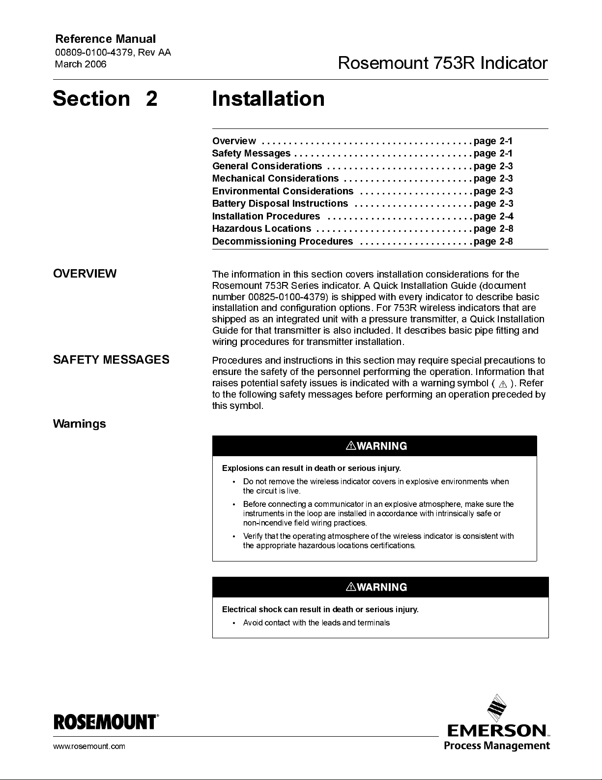
Explosions can result in death or serious injury.
• Do not remove the wireless indicator covers in explosive en vironm ents when
the circuit is live.
• Before connec t in g a c ommuni c at or in an explosive atmosph ere, make s ur e th e
instruments in the loop are installed i n accordance with intrinsically safe or
non-incendive field wiring practices.
• Verify that the operating atmosphere of the wireless indicator is consistent with
the appropriate hazardous locations certifications.
www.rosemount.com
Electrical shock can result in death or serious injury.
• Avoid co nta ct w ith the leads and te rm in als

Rosemount 753R Indicator
Replacement equipment or spare parts must be approved by Rosemount Inc. for use.
Spare parts not approved my Rosmount Inc. could reduce performance and may
render the instrument dangerous.
• Use only bolts supplied or sold by Rosemount Inc. as spare parts
• For attached sensors, refer to the respective manual for replacement equipment
and spare parts information.
The unit must be installed in a manner that provides a minimum separation distance
of 8 inches (20 centimeters) or more between the antenna and personnel in order to
satisfy FCC RF exposure requirements for mobile transmitting devices.
Reference Manual
00809-0100-4379, Rev AA
March 2006
Web based monitoring is intended for monitoring opoerations only, and is not
intended for any control operations. Data is not designed to integrate into Distributed
Control Systems. iTraX
Contact factory for more information.
Keep any source of fire or electri cal sparking away from the Remote Power Supply
(RPS) battery.
Battery disposal is the responsibility of the customer. Batteries must be disposed of
properly
Sealed batteries can emit hydrogen if overcharged. Temperatures over 572 °F (300
°C) may release combustible gases from battery.
.
®
data can be made available through optional connectivity.
2-2
When installing a Rosemount 753R with an Intrinsic Safety tr ansmitter, use the
appropriately sized Intrinsic Safety barrier.
Reference Manual
00809-0100-4379, Rev AA
March 2006
Rosemount 753 R Indica tor
GENERAL
CONSIDERATIONS
MECHANICAL
CONSIDERATIONS
ENVIRONMENTAL
CONSIDERATIONS
Meas urement accuracy depends upon proper i ns tallatio n of the sens or and
accessori es . M o unt the w ireless i ndi cat or accordi ng to bes t practi ces for the
installati on environment. Also, consi der th e need for easy access, personn el
safety, signal transmission integrity, access to power lines or direct or indirect
sunlight, and a sui ta ble wi reless indi cat or environment. I nsta ll the wire less
indicator to minimize vibration, sho ck, and temperature fluctuation. For
integrat ed uni ts , see tran smit ter-specific literature for more detailed
installati on i nstruct i ons .
RPS solar panel m ust be clean and clear of objects that could block access to
sunlight.
Due to the self discharge charact eri s tics of the batt ery, it must be charged
after 6-9 months of storage; otherwise, permanent loss of capacity might
occur as a result of sulfation
Avoi d i ns talling antenna around or near any large motors or other equipment
that could create strong Radi o Freq uency Interference (RFI).
Following suggested access requirements and proper transmitt er mounting
and cover in sta llation procedures can help optimize trans mit ter performance.
See “transmitter-specific” manual for details.
Direct or indirect sunlight is requi red for opti onal RPS to functi on .
If disposing of a battery, follow specified instructions below.
BATTERY DISPOSAL
INSTRUCTIONS
A Material Safety Data Sheet for the battery is available upon request.
Power-So ni c Sealed M aintenance Free Lead-Aci d B att eri es (M o del No.
PS-612) Rosemount Pa rt No. 753-90 02-0001
Waste Disposal M et hod:
Spent batteries must be treated as hazardou s waste and disposed of
according to local, state, and federal guidelines. A copy of the MSDS must be
supplied to any scrap dealer or secondary lead smelter along with the battery.
MSDS: www.power-sonic.com
Replacement batteries should be the same make and model as the factory
iss ued bat tery.
2-3
Rosemount 753R Indicator
INSTALLATION
PROCEDURES
Reference Manual
00809-0100-4379, Rev AA
March 2006
Site Evaluation
Device Installation
Consider Housing
Rotation
The 753R installation site must meet the followin g criteria for proper
operation:
1. Access to a power so urce
a. Direct or indirect sunlight for Remote Power Supply, or
b. 6 to 24 VDC line power
2. Installation locati on w i t hi n cellular (GPRS) cov erage area
Installi ng the 753 R Com m un ica tions Hou sin g
1. Mount the 753R upri ght us i ng the appropri at e brackets and fixtures.
2. Mount remote measurement transmitter(s) as recommended by its
respective installation instructions.
Installi ng a 753R with I n tegra ted Pr essu re Transmitter
1. Mount the 753R w i t h i nteg rated pres s ure trans mit ter cons i st ent w i t h i ts
respective Quick Installation Guide.
NOTE
Best practice is to ins tall the devi ce i n a v e rti cal and upri ght pos i t i on.
Posi tion the antenna in a vertical orientati on for best si gn al receptio n.
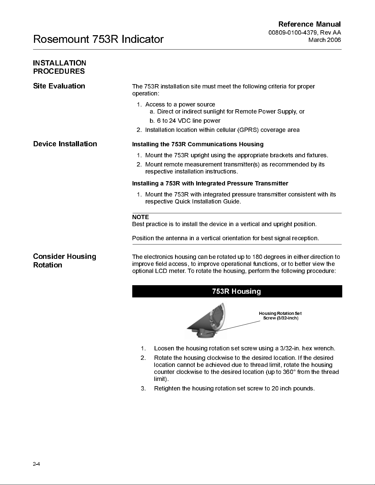
The electronics housing can be rotated up to 180 degrees in either direction to
improve field access, to improve operational functions, or to better view the
optional LCD meter. To rotate the housi n g, perform the following procedure:
2-4
753R Housing
Housing Rotation Set
Screw (3/32-inch)
1. Loosen the hous i ng rotat ion s et s crew usi n g a 3/32-i n. hex wrench.
2. Rotate the housing clockwise to the desired location. If the desired
location cannot be achi eved due to thread limit, rotate the hous i ng
counter clockwise t o the des ired locati on (up to 360 ° from the thread
limit).
3. Retight en the housing rotation set screw to 20 inch poun ds .
Reference Manual
00809-0100-4379, Rev AA
March 2006
Rosemount 753 R Indica tor
LCD Meter Rotation
Consider RPS
Positioning
In addition to housin g rotation, the optional LCD meter can be rotated in
90-degree increments. To rotate the LCD meter, remove the front housi n g
cover (this may require a wrench). Squeeze the tw o tabs located on the sides
of the LCD meter and lift the meter out. Rotat e the LCD meter to the des i red
directi on and s nap back into place. Replace the front hous i ng cover and
tighten.
NOTE
The jumpers may come loose while removi ng th e LCD meter. Be sure that
they are fully seated in the housing before snapping the LCD meter int o place.
When installing the optional Remote Power Supply (RPS), position the solar
panel so that it has t he best possible access to sunlight throughout the day. If
direct sunlight access is not available, indirect (reflected) sunlight sources can
be used.
2-5
Rosemount 753R Indicator
Reference Manual
00809-0100-4379, Rev AA
March 2006
Connect Wiring and
Power Up for Integrated
Transmitters
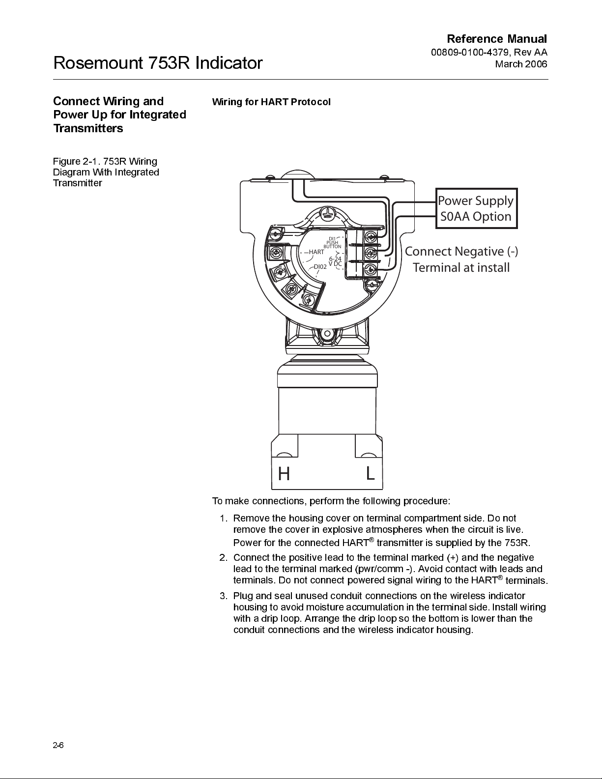
Figure 2-1. 753R Wiri n g
Diagram With Int egrat ed
Transmitter
Wiring for HART Protocol
BUTTON
HART
DI02
DI1
PUSH
6-24
V DC
Power Supply
S0AA Option
Connect Negative (-)
Terminal at install
2-6
H
To make connections, perform the following procedure:
1. Remove the housin g cov er on terminal compartment side. Do not
remove the cove r in explosi v e atmospheres w hen the ci rcuit i s li v e .
Power for the connected HA RT
2. Connect the posit i ve lead to the terminal marked (+) and the negati ve
lead to the terminal marked (pwr/comm -). Avoid contact with leads and
terminals. Do not connect powered signal wiring to t he HART
3. Plug and seal unused conduit connect i ons on the w i reless indicator
housing to avoid moisture accumul ation in the term inal side. Install wiring
with a drip loop. Arrange the drip loop so the bottom is lower than the
conduit connections and the wi reless i ndi cator hous i n g.
L
®
transmitter is supplied by the 753R.
®
terminals.
Reference Manual
00809-0100-4379, Rev AA
March 2006
Connect Wiring and
Power Up for Remote
Mounted Transmitters
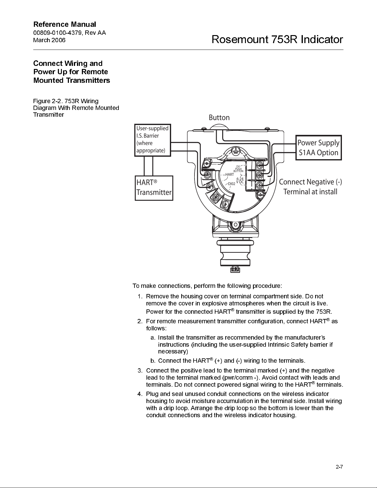
Figure 2-2. 753R Wiri n g
Diagram With Remote Mount ed
Transmitter
User-supplied
I.S. Barrier
(where
appropriate)
HART®
Transmitter
Rosemount 753 R Indica tor
Button
Power Supply
S1AA Option
DI1
PUSH
BUTTON
HART
6-24
DI02
V DC
Connect Negative (-)
Terminal at install
To make connections, perform the following procedure:
1. Remove the housin g cov er on terminal compartment side. Do not
remove the cove r in explosi v e atmospheres w hen the ci rcuit i s li v e .
Power for the connected HA RT
2. For remote measurement transmitter configurati on, connect HART
follows:
a. Ins tall the transmit ter as recommended by the manufacturer’s
instructions (including the user-supplied Intrinsic Safety barrier if
necessary)
®
b. Connect the HART
3. Connect the posit i ve lead to the terminal marked (+) and the negati ve
lead to the terminal marked (pwr/comm -). Avoid contact with leads and
terminals. Do not connect powered signal wiring to t he HART
4. Plug and seal unused conduit connect i ons on the w i reless indicator
housing to avoid moisture accumul ation in the term inal side. Install wiring
with a drip loop. Arrange the drip loop so the bottom is lower than the
conduit connections and the wi reless i ndi cator hous i n g.
(+) and (-) wiring t o the termina ls.
®
transmitter is supplied by the 753R.
®
terminals.
®
as
2-7
Rosemount 753R Indicator
Signal Wiring Grounding
Do not run signal wi ring in conduit or open trays wit h pow er w iri ng, or near
heavy electrical equipment.
Reference Manual
00809-0100-4379, Rev AA
March 2006
HAZARDOUS
LOCATIONS
Grounding the Wireless
Indicator Case
DECOMMISSIONING
PROCEDURES
The Rosemount 753R and any attache d dev ices must be installed according
to the guideli nes and certi fi cat ions lis t ed i n their respective user manuals.
NOTE
Once a devi ce labeled wi th multiple approv a ls is i ns talled, it sh ould not be
reinstalled usi ng any other approval ty pe(s ). Pe rmanently mark the
certificat ion label to dis t i nguish the ins talled approv al ty pe from unused
approval ty p es .
Always ground the wireless indicator case in accordance with national and
local electrical codes. The most effective wireless indicator case grounding
method is a direct connect i on t o earth ground w it h mini mal impedance.
Methods for grounding the wireless indicator case include:
•
Internal Ground Connection
is i ns i de th e terminal si de of the electronics hous i ng. The screw i s
identi fi ed by a grou nd sy mbol ( ), and is s tandard on all Model 753R
Series indicators.
Please be familiar wi th all warni ngs before attempti ng t o decommissi on your
753R. See “Warnings” on page 2-1.
Explosions can result in death or serious injury.
• Do not remove the wireless indicator covers in explosive en vironm ents when the
circuit is live.
• Before connecting a communicator in an explosive atmosphere, make sure the
instruments in the loop are installed i n accordance with intrinsically safe or
non-incendive field wiring practices.
• Verify that the operating atmosphere of the wireless indicator is consistent with the
appropriate hazardous locations certifications.
: The Internal Ground Connection screw
2-8
Electrical shock can result in death or serious injury.
• Avoid co nta ct w ith the leads and te rm in als

Reference Manual
00809-0100-4379, Rev AA
March 2006
Rosemount 753 R Indica tor
Physical/Process
Decommissioning
Service Decomissioning
753R with Inegr al P ressu re Transmitter
Please refer to the pressure transmitter manual for physical detachment from
the process.
753R with Remote Power Su pp ly
Open the si de of the hous i ng marked
negative (-)
753R with Line Power Su pp ly
Open the si de of the hous i ng marked
negative (-)
Please call RCC to cancel the iTraX® serv i ce. Tag information will be needed
to complete the decommissioning process.
Warning - service charges w i ll continue to be billed unless a decommissi on
request is made wi t h Rosemount.
terminal from the power sup ply.
terminal from the power sup ply.
FIELD TERMINALS
FIELD TERMINALS
. Disconnect the
. Disconnect the
2-9

Rosemount 753R Indicator
Reference Manual
00809-0100-4379, Rev AA
March 2006
2-10

Reference Manual
00809-0100-4379, Rev AA
March 2006
Rosemount 753 R Indica tor
Section 3 Web Interface-Connectivity
Overview . . . . . . . . . . . . . . . . . . . . . . . . . . . . . . . . . . . . . . .page 3-1
Starting iTraX® . . . . . . . . . . . . . . . . . . . . . . . . . . . . . . . . . .page 3-1
Navigating the iTraX® Applicatio n Win do w . . . . . . . . . . . page 3-2
Navigating the iTraX® Applicatio n Win do w . . . . . . . . . . . page 3-2
Account . . . . . . . . . . . . . . . . . . . . . . . . . . . . . . . . . . . . . . . .page 3-3
Manag in g iTraX® Accounts . . . . . . . . . . . . . . . . . . . . . . . . page 3-4
Security Provisions . . . . . . . . . . . . . . . . . . . . . . . . . . . . . .page 3-6
OVERVIEW
STARTING ITRAX
Figure 3-1. User Login
This section contains i nformation about how to use i TraX® interface.
®
To s ta rt i Tra X®:
1. Open a web browser and ent er the following si t e URL:
https://www.emersonprocess.com/rosemount/products/accessories/m75
3_content.html
2. Select the iTraX
®
icon at the top of th page or from the ITraX® tab at the
bottom.
®
3. In the iTraX
User Login, enter your User ID and Password and click the
“Login” butto n.
www.rosemount.com
S
F
I
T
.
B
A
N
I
G
O
L
/
3
5
7

Rosemount 753R Indicator
NOTE
The master User ID cannot be changed by the user. It is permanently
assigned by Rosem ount as the account holder name for the user. If it is lost or
forgotten, contact RCC.
Reference Manual
00809-0100-4379, Rev AA
March 2006
NAVIGATING THE
ITRAX® APPLICATION
WINDOW
Application Menu
Application Workspace
User Help
E-Mail Assistance
Reset
The iTraX®Application Window allows you to easily navigate the website and
features the following components:
The Application menu allows for quick and easy selection of the desired
functions w hi ch include:
• Reports - to view Summary, History, and Alert reports for any device
• Configuration - to set configurations for each device, including general,
measurement, alert, query request, and e-mail notification
configurations
• Account - manages account settings, i ncluding user profile and
additi on al accounts. Current user may also reload or log out from this
area.
The Applicatio n Workspace allows the user to v iew tables, enter data and
manage iTraX
®
account information.
The User Help button provi d es access to the on-li ne manual with d irecti o ns
on how to resolv e problems and implement desired applicat i ons .
The E-mail Assis tance but to n allows the user to s end an e-mail request for
information or help beyo nd the s cope of the manual and on-line help.
The Reset button (not shown) is found on each data entry page. Clicking the
Reset butt on returns all data entry spaces on a page to the default se tt i ngs.
Figure 3-2. iTraX
Window
3-2
®
Application
Application Tabs
E-mail
assistance
Application
Workspace
User Help
F
I
T
.
A
A
1
0
_
Y
R
A
M
M
U
S

Reference Manual
00809-0100-4379, Rev AA
March 2006
ACCOUNT
Rosemount 753 R Indica tor
User Profile
Figure 3-3. User Profile Settings
The User Profile page allows the user to v iew current user settings.
Time Zone
To change the Time Zone setti n g:
1. Select the
Time Zone
for this account us i ng the drop-dow n menu.
2. Choose the appropri at e regi on.
3. Click
Save
.
Password
To change the Us er Pas s w ord:
1. Select the
2. Enter the
3. Determine a new password and enter it in the
4. Re-enter the passw ord i n t he
Change Password
Old Password
in the field prov i de d.
link on the User Profi le page.
New Password
Confi rmed New Password
field to
confirm proper spelling.
5. Click
Submit
to activate the new password.
6. If a User Password is forgotten, it can be found using the User Master
account.
field.
F
I
T
.
A
A
_
3
1
_
3
5
7
/
3
5
7
Figure 3-4. Change User
Password
3-3
F
I
T
.
A
A
_
4
1
_
3
5
7
/
3
5
7

Rosemount 753R Indicator
Reference Manual
00809-0100-4379, Rev AA
March 2006
MANAGING ITRAX®
ACCOUNTS
Figure 3-5. Account
Management
Edit Existing Account
The iTraX® Account M anagement page lets y ou add or create addi t i ona l
sub-accounts to a User ID. It also provides the time and date that the account
was established and when it is s cheduled to expire.
To delete an account, click on the
Delete
link nex t t o the account login y ou
wish to remove.
To change the s et ti n gs of an existi ng account :
1. Select the highli ght ed login name you w i s h to edi t .
2. Change any of the des i red s ett ing s w hi ch i nclude:
•
Effective
•
Expiration
• Selecting the
- date and time that account access begi ns .
- date and time that account access ends .
Never Expires
box continues access indefinitely
and overri des the expirati o n setting.
•
Time Zone
- Set the appropriat e ti me zone to the spe ci fi c user
location.
•
Tags
- Set tags that the specific account user may access.
•
A c cess Rig hts
- A check mark in thi s box lets the user change
device configurations.
F
I
T
.
A
A
_
7
1
_
3
5
7
/
3
5
7
Figure 3-6. Edit Account
3-4
F
I
T
.
A
A
_
6
1
_
3
5
7
/
3
5
7

Reference Manual
00809-0100-4379, Rev AA
March 2006
Rosemount 753 R Indica tor
Set Up New Account
Figure 3-7. New Account Setup
To create a New Account:
1. Select the
2. Choose a
New Acco unt
User ID
box.
3. Choose a
Password
box.
4. Set the
5. Set the
Effective
Expiration
expiration date and time is not desi red or is currently unknown, check
the
Never Expi res
6. Choose the
7. Choose the
Time Zone
Tags
8. If desired, give the user
putting a check mark in the box.
9. Click
Submit
to establish the new account.
link in the Account M ana gement page.
for this sp eci fi c account use r and enter i t in th e
for this spe ci fi c account user and ent er it i n th e
date and time that the user account is active.
date and time, if des i red. I f a speci fi c account
box .
appropriate to t he locati on of the user.
that the us er is given access to.
Device Config ur atio n
access rights by
F
I
T
.
A
A
_
5
1
_
3
5
7
/
3
5
7
3-5

Rosemount 753R Indicator
Reference Manual
00809-0100-4379, Rev AA
March 2006
Changing Users
Figure 3-8. Logout
SECURITY PROVISIONS
To change users during an active session:
1. Click the
2. Enter the new
Logout
User ID
option on the left menu.
and
Password
information on the main
screen.
3. Click
Submit
.
F
I
T
.
A
A
_
8
1
_
3
5
7
/
3
5
7
The iTraX® internet portal incorporat es several key security provisions to
ensure that data s torage is bot h reliable and secure:
•
Password Protection
- Ensures that only the intended users have
access to trans mitt er data. I t is recommended that users change th e
login passw ord regularly to provide addi ti onal securi t y.
•
Website User Access Time-out
- When the iTraX
®
interface remains
unused for 15 minutes, t he use r must re-enter login i nformatio n.
®
•
Centralized, Secure Server
-The iTraX
system stores all user data
on a secure, thi rd party s erv e r.
•
Encrypted/Authenticated Data Transmissions
- The iTraX
®
sys t em
secures data through state-of-the-art encryption and authentication
techniques.
•
3-6

Reference Manual
00809-0100-4379, Rev AA
March 2006
Rosemount 753 R Indica tor
3-7

Rosemount 753R Indicator
Reference Manual
00809-0100-4379, Rev AA
March 2006
3-8

Reference Manual
00809-0100-4379, Rev AA
March 2006
Rosemount 753 R Indica tor
Section 4 W eb Interface-Configuration and
Maintenance
Overview . . . . . . . . . . . . . . . . . . . . . . . . . . . . . . . . . . . . . . .page 4-1
Device Configuration . . . . . . . . . . . . . . . . . . . . . . . . . . . . .page 4-1
Measurement . . . . . . . . . . . . . . . . . . . . . . . . . . . . . . . . . . . . page 4-2
Alert . . . . . . . . . . . . . . . . . . . . . . . . . . . . . . . . . . . . . . . . . . .page 4-3
Query Request . . . . . . . . . . . . . . . . . . . . . . . . . . . . . . . . . .page 4-4
E-Mail Notification . . . . . . . . . . . . . . . . . . . . . . . . . . . . . . .page 4-5
General . . . . . . . . . . . . . . . . . . . . . . . . . . . . . . . . . . . . . . . .page 4-6
Discrete Output . . . . . . . . . . . . . . . . . . . . . . . . . . . . . . . . . .page 4-7
Discrete Input . . . . . . . . . . . . . . . . . . . . . . . . . . . . . . . . . . . page 4-7
Master Reset . . . . . . . . . . . . . . . . . . . . . . . . . . . . . . . . . . . . page 4-7
OVERVIEW
DEVICE
CONFIGURATION
Figure 4-1. Device Configurati on
This section contains i nformation on configurat ion of the 753R i nd i cator. Full
devi ce confi gurat ion i s performed vi a the i TraX
®
web int erface.
The device configuration section of the iTraX® website allows you to select the
particular devi ce tag you wish to confi gure throu gh a pull-down menu. To
access the device configurati on, click the device on the left menu.
Once you have selected the device you wish to configure, the following
configurati on opt ions are av a i lable:
•
Measurement
- Change the device tag name; Set device
measurement parameters; Set transmission parameters; Enter an
e-mail address to receive a configuration acknow ledgement.
•
Alerts
- Set alert parameters; Define effective and expiration dates;
Configure e-mail setti ng s t o receive electronic alert notificat i on.
•
Query Request
- Request configurat i on from a transmitter at th e next
transmission.
•
E-mail Notification
- Establish e-mail addresses that will receive
electronic data transmis si ons duri ng device operati on .
•
General
- Configure setti n gs related to the physical devi ce; Ent er an
e-mail address to receive a configuration acknow ledgement.
•
Discrete Output
- Set discrete output parameters; Enter an e-mail
address to recei ve a configuration acknow ledgement.
•
Discrete Input
•
Master Reset
- See factory for av ai labi li ty.
- Perform a master reset of selected device tags; Enter
an e-mail address to receive a configuration acknowledgement.
F
I
T
.
A
A
_
2
0
_
3
5
7
www.rosemount.com

Rosemount 753R Indicator
Reference Manual
00809-0100-4379, Rev AA
March 2006
MEASUREMENT
Meas urement configurat i on allows y ou to set or change the following
measurement parameters for any trans mit ter:
•
Edit Tag Name
- wireless i nd i cators are shi pped w i t h pre-confi gured
tag names that are tied to the Device ID. Tag names can be changed at
any time by entering a new name in the space provided and clicking the
Submit butto n.
•
Type
- Choose from the following opt i ons to descri be t he spe cifi c
devi ce i dent ifi ed by the Tag Name:
•No Device
•HART Device
•
Variables to Transmit
- Select any of the following HART transmitter
vari ables t o trans mit:
•PV - Primary Variable (1st)
•SV - Secondary Variable (2nd)
•TV - Terti ary Variable (3rd)
•
QV
- Quaternary Variable (4th)
•
Read/Transmit Interval
- Set the int erval for reading and transmittin g
data.
•
HART Address
the system to assign it automatically (Auto), or by choosing an address
between 1 and 15 that matches the connect ed HART
•
Turn-On T i m e
Transm itter requires to provide valid data. (default is 2 seconds, refer to
respective HART
•
Device ID
•
Acknowledgement E-mail
- Select the HART mul tidrop address either by allowing
®
Transmitter.
- Enter the number of seconds that the HA RT
®
Transmitter manual for best practices)
- Indicates the HART ID of the installed transmitter.
- Enter an e-mail address to receive an
®
acknowledgement of the changes to the measurement configurat i on
settings, i f desired.
•
Submit
- After all settings have bee n chosen , click Submit to acti v at e
the settings.
Example: The following example shows a HART device with the tag name
753-MV T1-02 trans mitt i ng P rimary and Secondary Variables. The transmit
interval is set to read ev ery 15 minut es and trans mit every hour at HART
Address 1. Turn-On time is set to 4 se conds .
Figure 4-2. Measurement
Configuration
4-2
F
I
T
.
A
A
_
3
0
_
3
5
7

Reference Manual
00809-0100-4379, Rev AA
March 2006
Rosemount 753 R Indica tor
ALERT
To establish a new Alert setting, follow these steps:
1.
Alert Number
2.
Alert Mode
particular Tag, and
particular Tag. Note th at w hen an alert i s set to Di s able, the s et ti n gs
remain in the system, but no a larm notifications are sent.
3.
Alert Name
4.
Variable Assignment
a.PV - Primary Variable
b.SV - Secondary Variable
c.TV - Tertiary Variable
d.QV - Quaternary Variable
5.
Direction
a.
Rising
the pre-determined alert set poi nt .
b.
Falling
the pre-determined alert set poi nt .
c.
Both
across the pre-det ermined alert set poi nt (rising or falling).
6.
Unit
- Select which unit of measurement (e.g., psi) applies to the
measured variable. The unit must match the unit selected in the attached
™
HART
7.
Set Point
measured vari able should acti vate the alert notificat i on.
8.
Dead Band
must return beyond the se t poi nt before the device resets from an alert
status.
9.
E-mail Notification
Operatio ns E -mail account when the alert is activated. Su bject and
Mess ag e spaces are prov i de d to offer addition al details regarding the
specific alert notification being distributed.
10.
Acknowledgement E-mail
acknowledgement of the changes to the alert configurat i on set ti n gs, i f
desired.
11.
Submit
settings.
- Choose a number from the drop down menu 1-10.
- Toggle betwee n
Disable
- Enter a name in the space provi ded t o label the alert.
- Select which variable activates the alert:
- Select which di rection of change will activ at e the alarm:
- Activates the alert whe n the measured variable rises past
- Activates the alert when the measured variable falls below
- Activ a tes the alert when th e measured v ari able moves
transmitte r.
- Set the numeric va lue that repres ents the poi n t at which the
- Set the numeric va lue that repres ents how far the v ari able
- An electronic alert notifi cat i on i s se nt to the
- After all settings have been chosen, click Submit to activate the
Enable
, to deacti vate the Alert set tin gs for a
- Enter an e-mail address to receive an
, to activate the Alert s ettings for a
4-3

Reference Manual
00809-0100-4379, Rev AA
Rosemount 753R Indicator
Ex a mple: The following example shows configu rati o n for a Disab le Alert Mo de at Low
Level for the Primary Variable. It also show s the email notifi cati on messag e
that wi ll be deliv ered w hen the alarm is trigg ered.
Figure 4-3. Alert Confi gurat i on
Latching be havi or
March 2006
F
I
T
.
A
A
_
6
0
_
3
5
7
QUERY REQUEST
When a measurement crosses a predefined setpoint, the 753R sends an alert
back to the iTraX
®
websi t e. The 753R then waits for the measurement to
move a certain amount back within the “safe operating range” before resetting
the alert. This delay i s called “dead band” and helps prevents rapi d on/off
cycling of alerts.
Process
Dead
Band
Fill Level
S
P
E
.
G
N
I
H
C
T
A
L
_
3
5
7
\
3
5
7
Tan k
Fill
Alert 1 Clears
Alert 1:
Low Level
Tan k
Fill
Tan k
Low
Level
To perform a Query Request, which confirms teh 753R configuration
parameters via email at the next transmission:
1. Select the desired data type from the available
2. Enter an e-mail address in the space provided next to
Query Type
Query E-mail
list.
that
the data wi ll be sent to.
3. Click
Submit
to process the reques t.
4-4

Reference Manual
00809-0100-4379, Rev AA
March 2006
Example: The following example shows configuration for a General Query Request.
Figure 4-4. Query Request
Configuration
Rosemount 753 R Indica tor
F
I
T
.
A
A
_
7
0
_
3
5
7
E-MAIL NOTIFICATION
Figure 4-5. E-Mail Notification
Configuration
The notification e-mail configuration page lets the user set up e-mail accounts
that wi ll receiv e electroni c not i fications related to the selected tags .
E-mail accounts that may be entered include:
•
Main tenan ce E-m ai l
•
Operations/Dispatch E-mail
•
General E-mail
Click Submit to process the s etti ng s.
F
I
T
.
A
A
_
8
0
_
3
5
7
4-5

Rosemount 753R Indicator
Reference Manual
00809-0100-4379, Rev AA
March 2006
GENERAL
The general configuration se tt i ngs let the user change the followi ng set t i ngs :
•
Button Event Time-out
- Sets the time, in seconds, that the local LCD
screen displays data when the local user interface button has been
pressed.
•
Power Mode
- Toggle the power mode of the wi reless i ndi cat or
between tw o set tings:
• Normal - The wireless indicator is maintained in a power-saving sleep
mode until it is pow ered up to perform an operation . After operati on,
the wireless indicator returns to the sleep mode. This setting is best
when the device is powered locally with a Remote Power Supply
(RPS).
• Always On - The wireless indicator is in constant power mode (does
not enter a sleep m ode when not operating). This power mode should
only be used for dev i ces that a re line powered th rough a con tin uous
power supply.
NOTE
When used with the RPS, Always On mode will deplete the battery at a higher
rate than normal.
•
Acknowledgement E-mail
- Enter an e-mail address to receive an
acknowledgement of the changes to the general configuration settings,
if desired.
•
Submit
- After all settings have been chosen, click Submit to activate
the settings.
Ex a mple: The following example shows the Gene ral Configurat ion se tt i ngs . But to n
Event Time-out is set to 30 min. in normal Power Mode.
Figure 4-6. General
Configuration
F
I
T
.
A
A
_
3
0
_
3
5
7
4-6

Reference Manual
00809-0100-4379, Rev AA
March 2006
Rosemount 753 R Indica tor
DISCRETE OUTPUT
Discrete Outpu t functi on ality is only available when the Rosemount 753R i s
ordered wit h the Y1 Discrete I / O opt i on.
To configure the Discrete Output set tings of selected Tags, follow these steps:
1.
DO Mode
- Toggle this setting to
Enable
or
Disable
the Discrete Output
option
2.
DO Trigger Alert
3.
DO Direction
- Set the alert that w i ll trigger Dis crete Out put .
- The DO Direction can be set to Low >Hi gh or Hig h>Low
(see Alert on page 4-3 for more information).
4.
Acknowledgement E-mail
- Enter an e-mail address to receive an
acknowledgement of the changes to the di s crete out put configu ratio n
settings, i f desired.
5.
Submit
- After choosing all setti ngs , click
Submit
to activate.
Example: The following example shows configuration for the Discrete Output. It shows
that DO M ode i s enabled, DO Trigger Alert is L ow Lev el (Disa bled), and the
DO Directi on is Low >Hi g h.
Figure 4-7. Discrete Output
Configuration
DISCRETE INPUT
MASTER RESET
See factory for availability.
The iTraX® Mast er Res et opt i on performs a “reboot” of the selected w i reless
indi cators di rectly from the webs i te . The reboot w i ll occur at the nex t
scheduled transmission.
To activate a master reset operation:
1.
Acknowledgement E-mail
- Enter an e-mail address to receive an
acknowledgement of the Mast er Res et.
2.
Submit
- Click Submit to activate the master reset.
F
I
T
.
A
A
_
4
0
_
3
5
7
4-7

Reference Manual
00809-0100-4379, Rev AA
Rosemount 753R Indicator
Ex a mple: The following example shows configu rati o n for fiv e tags to be res et.
Figure 4-8. Master Reset
March 2006
F
I
T
.
A
A
_
9
0
_
3
5
7
4-8

Reference Manual
00809-0100-4379, Rev AA
March 2006
Rosemount 753 R Indica tor
Section 5 Web Interface-Data Viewing
Overview . . . . . . . . . . . . . . . . . . . . . . . . . . . . . . . . . . . . . . .page 5-1
Summary Reports . . . . . . . . . . . . . . . . . . . . . . . . . . . . . . . .page 5-1
History Reports . . . . . . . . . . . . . . . . . . . . . . . . . . . . . . . . . .page 5-3
Alert Reports . . . . . . . . . . . . . . . . . . . . . . . . . . . . . . . . . . . .page 5-5
OVERVIEW
SUMMARY REPORTS
This section contains i nformation on operati o n and maintena nce techni q ues
for the Rosemount 753R wireles s i nd i cato r.
This page allows the use r to v i ew a
operationa l status and the lates t read informati on for each wi reless i ndi cat or
in the user account .
To v i e w a summary of wireles s i nd i cato r data:
1. Select the desired
• Choose one speci fi c tag by highli ght i ng i t
• Choose multiple tags by holding t he Control (Ctrl) button on the
keyboard and s electi ng all desired tags
• Choose all applicable tags by selecting the asterisk (*)
2. Click
Summary Report data includes:
•
•
•
•
•
•
•
Submit
Tag
- Identi fie r ass oci ated w i t h a speci fi c w i reless i ndi cat or.
Time
- The last time that a reading was made by the identified wireless
indicator.
PV
- Primary Variable measurement reading
SV
- Secondary Variable measurement reading
TV
- Tertiary Variable measurement reading
QV
- Quaternary Variable measurement reading
Status
- Indicates any current operational problems with a specific
wireless i ndi cator, which can be v iewed by clicki ng on the hi gh light ed
value. Potential problems that may be identified include:
Tag(s)
.
Summary Report
by one of the following opti ons:
that presents
www.rosemount.com
Table 5-1. Status M es sa ges
First message since power was
753R Cold Start
753R Device Malfunction
753R Low Battery
applid or a master reset
occurred
Malfunction of 753R indicator Reconfigure all settings or
Battery voltage is low Recharge or replace battery
No action
replace unit

Rosemount 753R Indicator
Table 5-1. Status M es sa ges
753R DB Overrun
Slave Device
Disconnected
Slave Device Malfunction
Slave Device
Configuration Error
Discre te O utpu t Ac tive
Button Error
Slave Device Saturated
Data Packet Checksum
Error
753R Power Always On
Reference Manual
00809-0100-4379, Rev AA
March 2006
Buffer memory exceeded
capacity
Transmitter not reporting to
753R
Slave device is reporting a
malfunction
Alert unit mis-match or device
address mis-match
Alert has caused the DO to be
activated
Button event active or in
process
HART transmitter satura ted See device manual or check
Data associated with a packe t
implies an error; could be
corrupted
Device in Power Always On
mode
No action required
Check connections and/or
HART™ address
Replace HART™ transmitter,
refer to HART™ device manual
for corre ctive action
Check Alert units and/or see
device replacement instructions
No action required
No action required
process
If error persists, call RCC
If desired mode, no action
required. If not desired, change
pow e r mode.
Figure 5-1. Summary Report
•Alert
- Indicate s any current alert notificat i ons at tribu table to a speci fi c
wireless i ndicator tag name, which can be viewed by clickin g on the
highlight ed v alue for detailed alert information.
•
Battery Voltage
- Current voltage level of the wi reless i ndicat or’s
battery.
•
RSSI
- Radio Sig nal Strength Ind icato r - Show s t he st rengt h of the
radio signal reception at the specific device location.
•
Received Time
- Shows the time that the data was received.
F
I
T
.
A
A
1
0
_
Y
R
A
M
M
U
S
/
3
5
7
5-2

Reference Manual
00809-0100-4379, Rev AA
March 2006
Rosemount 753 R Indica tor
HISTORY REPORTS
This page allows the user to generate a histori ca l report on any device tag. To
vi ew a hi s tory report of wireless in di cat or data, us e the followi ng st eps :
1. Select the desired
• Choose one speci fi c tag by highli ght i ng i t
• Choose multiple tags by holding t he Control (Ctrl) button on the
keyboard and s electi ng all desired tags
• Choose all tags by selecti n g the as terisk (*)
2. Choose a starting date and time in the
using th e pull-down menus or clicking on the “…” i con to acces s an
interactive calendar.
3. Choose an ending date and t i me in the
using th e pull-down menus or clicking on the “…” i con to acces s an
interactive calendar.
4. Click
NOTE
Click
History Report
•
•
•
•
•
•
•
Submit
Reload
to refresh the page wi th the current s ett i ng s.
data includes:
Tag
- Identi fie r ass oci ated w i t h a speci fi c w i reless i ndi cat or.
Time
- The time the reading was taken by th e i dent i fi ed w i reless
indicator.
PV
- Primary Variable measurement reading
SV
- Secondary Variable measurement reading
TV
- Terti ary Variable measurement reading
QV
- Quaternary Variable measurement reading
Status
- Indicates any current operational problems with a specific
wireless i ndi cator, which can be v iewed by clicki ng on the hi gh light ed
value. Potential problems that may be identified include:
Tag(s)
by one of the following opti ons:
From:
data entry section by either
To:
data entry sect i on by either
.
5-3

Rosemount 753R Indicator
Table 5-2. Status M es sa ges
753R Cold Start
753R Device Malfunction
753R Low Battery
753R DB Overrun
Slave Device
Disconnected
Slave Device
Malfunction
Slave Device
Configuration Error
Discre te O utpu t Ac tive
Button Error
Slave Device Saturated
Data Packet Checksum
Error
753R Power Always On
Reference Manual
00809-0100-4379, Rev AA
March 2006
First message since power was
applid or a master reset occurred
Mal function of 753R indicator Reconf i gu re all s et ti ng s or r epl ace
Battery voltage is low Recharge or replace battery
Buffer memory exceeded
capacity
Transmitter not reporting to 753R Check connections and/or
Slave device is reporting a
malfunction
Alert unit mis-match or device
address mis-match
Alert has caused the DO to be
activated
Button event active or in process No action required
HART transmitter saturated See device manual or check
Data associated with a packet
implies an error; could be
corrupted
Device in Power Always On mode If desired mode, no action
No action
unit
No action required
HART™ address
Replace H AR T ™ t rans mitt er , r ef er
to HART™ device manual for
corrective action
Check Alert units and/or see
device replacement instructions
No action required
process
If error persists, call RCC
required. If not desired, change
power mode.
Figure 5-2. Hi sto ry Report
•
Alert
- Indicate s any current alert notificat i ons at tribu table to a speci fi c
wireless i ndicator tag name, which can be viewed by clickin g on the
highlight ed v alue for detailed alert information.
•
Battery Voltage
- Voltage level of the wireless indicator’s battery at the
time of the transmiss i on .
•
RSSI
- Radio Sig nal Strength Ind icato r - Show s t he st rengt h of the
radio signal reception at the specific device location.
•
Received Time
- Shows the time that the data was received.
F
I
T
.
A
A
1
0
_
Y
R
O
T
S
I
H
/
3
5
7
5-4

Reference Manual
00809-0100-4379, Rev AA
March 2006
Rosemount 753 R Indica tor
ALERT REPORTS
The Alert Report page allows the user to generate a s ummary of alerts
associated with a specific device. To view a history report of alert data, use
the following steps:
1. Select the desired
2. Choose the desi red
Tag
by highlighting it from the list of available tags.
Alert(s)
by one of the following options:
• Choose one speci fi c alert by highli ght i ng i t
• Choose multiple alerts by holding the Cont rol (Ctrl) button on the
keyboard and s electi ng all desired tags
• Choose all applicable alerts by selecti ng the as te ri s k (*)
3. Choose a starting date and time in the
From:
data entry section by either
using th e pull-down menus or clicking on the “…” i con to acces s an
interactive calendar.
4. Choose an ending date and t i me in the
To:
data entry sect i on by either
using th e pull-down menus or clicking on the “…” i con to acces s an
interactive calendar.
5. Click
Alert Report Summary
•
•
Submit
TagName
AlertName
.
data includes:
- Identifier associated with a specific wireless indicator.
- Identi fi es all current alert notificat ions at tri bu table to a
specific wireless indicator tag name, which can be viewed by clicking
on the highlighted value for detailed alert information.
•
Count
- Indicat es the number of occurences of the associ ated alert
wit hi n th e selected t i me span.
Alert Report Details
•
TagName
data includes:
- Identi fi er ass oci a ted w it h a spe ci fic w i reless i ndicator tag
name.
•
Time
- The time the alert was generated.
•
Battery
•
Alert Name
•
Variable
•
Value
- Current voltage level of the wi reless i ndicator battery.
- Label for the alert that was set by the user.
- Identifi es th e speci fi c variable being measured.
- Last measured numeric value associ a ted w i t h the id entified
variable.
•
Threshold
•
Status
- Value of the variable that will activate an alert.
- Indicates any current operational problems with a specific
wireless i ndi cator, which can be v iewed by clicki ng on the hi gh light ed
value. Potential problems that may be identified include:
Table 5-3. Status M es sa ges
753R Cold Start
753R Device Malfunction
753R Low Battery
753R DB Overrun
First message since power was
applied or a master reset
occurred
Malfunction of 753R indicator Reconfigure all settings or
Battery voltage is low Recharge or replace battery
Buffer memory exceeded
capacity
No action
replace unit
No action required
5-5

Rosemount 753R Indicator
Table 5-3. Status M es sa ges
Slave Device Disconnected
Slave Device Malfunction
Slave Device Configuration
Error
Discre te O utpu t Ac tive
Button Error
Slave Device Saturated
Data Packet Checksum
Error
753R Power Always On
Reference Manual
00809-0100-4379, Rev AA
March 2006
Transmitter not reporting to
753R
Slave device is reporting a
malfunction
Alert unit mis-match or device
address mis-match
Alert has caused the DO to be
activated
Button event active or in
process
HART transmitter saturated See device manual or check
Data associated with a packet
implies an erro r; co ul d be
corrupted
Dev ice in Po w e r Alw ays On
mode
Check connections and/or
HART™ address
Replace HART™ transmitter,
refer to HART™ device manual
for corrective action
Check Alert units and/or see
device replacement instructions
No action required
No action required
process
If error persists, call RCC
If desired mode, no action
required. If not desired, change
power mode.
Figure 5-3. Alert Report
•
RSSI
- Radio Sig nal Strength Ind icato r - Show s t he st rengt h of the
radio signal reception at the specific device location.
•
NotificationTime
- Time that each alert noti ficat i on i s se nt.
S
P
E
.
A
A
_
0
1
_
3
5
7
5-6

Reference Manual
00809-0100-4379, Rev AA
March 2006
Rosemount 753 R Indica tor
5-7

Rosemount 753R Indicator
Reference Manual
00809-0100-4379, Rev AA
March 2006
5-8

Reference Manual
00809-0100-4379, Rev AA
March 2006
Rosemount 753 R Indica tor
Section 6 Troubleshooting
Overview . . . . . . . . . . . . . . . . . . . . . . . . . . . . . . . . . . . . . . .page 6-1
Safety Messa ges . . . . . . . . . . . . . . . . . . . . . . . . . . . . . . . . . page 6-1
Disassemb ly P roc edu res . . . . . . . . . . . . . . . . . . . . . . . . . . page 6-3
Reassembl y Pro ced ures . . . . . . . . . . . . . . . . . . . . . . . . . . page 6-5
OVERVIEW
SAFETY MESSAGES
Warnings ( )
This section contains troub leshooti ng t echni que s for the most common
operating problems for the Rosemount 753R wireless indicator and the iTraX
web int erface.
Procedures and instructions in this section may require special precautions to
ensure the safety of the personnel performing the operations. Information that
raises potential safety i ssues is indicated by a warning symbol ( ). Refer to
the following safety messages before performing an operation preceded by
this symbol.
Explosions can result in death or serious injury.
• Do not remove the wireless indicator covers in explosive environments when
the circuit is live.
• Before connecting a communicator in an explosive atmosphere, make sure
that the instruments in the loop are installed according to intrinsically safe or
nonincendive field wiring practices.
Static electricity can dam a ge se ns itive com po ne nts.
• Observe safe handling precautions for static-sensitive components.
®
www.rosemount.com

Rosemount 753R Indicator
TROUBLESHOOTING
Symptom Addit iona l Sympto ms Recommended Action(s)
753R Not Responding
Not Recieving Email
Notifications
Not Recieving Alerts
No Discrete Output
Signal
Push-Button
Malfunction
LCD Not Working
All devices are not responding Probable server error
All devices in one geographic area not
responding
One unit not responding Check/replace battery
Other parts of device are working properly
®
(iTraX
)
Possible cell phone network outage. Check iTraX® for cell
coverage maintenance warnings.
Check RSSI (signal strength) in iTraX®. If <8, network quality
has be e n affecte d .
Check antenna connection
Examine all terminal connections
Cycle power and observe LCD
Press and hold Diagnostic Data Button for 10 seconds
Perform master reset of 753R
Verify email addresses entered correctly in iTraX
Make sure device is functioning
Check if alert is enabled in iTraX
Verify device is working properly and updating PV data.
Check alert configuration in iTraX
Check circuit connection
Check discrete output configuration in iTraX
Verify device is functioning and updating PV data.
Perform hold times according to instructions
Take resistive measurements across button terminals
Short circuit across button terminals
Cycle power
Re-seat LCD
Press and hold button for 4 seconds to initiate
reading/transmission
Reference Manual
00809-0100-4379, Rev AA
March 2006
®
®
®
®
6-2

Reference Manual
00809-0100-4379, Rev AA
March 2006
Rosemount 753 R Indica tor
DISASSEMBLY
PROCEDURES
Remove from Service
Remove from Service
Do not remove the ins t rument cov er i n explosive atmospheres when th e
circuit is live.
Be aware of the following:
• Follow all plant safety rules and procedures.
• Isolate and vent the process from t he transmitter before removing the
transmitte r from servi ce.
• Remove all electrical leads and conduit.
• Detach the process flange by removi ng t he four flange bolts and two
alignment screws t hat secure i t.
• Do not scratch, puncture, or depres s t he i so lati ng diaph ragms.
• Clean isolating diaphragms with a soft rag and a mild cleaning solution,
and rinse w i t h clear water.
• Whenever y ou remov e the proces s flange or flange adapters, v i s ually
inspect the Teflon o-rings. Replace the o-rings if they show any signs of
damage, such as nicks or cuts. I f they are not damaged, reuse them.
The 753R transmitter i s attached to the proces s connect i on by four bolts and
two cap screw s. Remove the bolts and se parate the trans mitt er from the
process connecti on . Leave the process connecti on i n place and ready for
re-installation.
To remove a wireless indicator from servi ce, “Decommissioning Procedures”
on page 2-8.
Remove Terminal Block
Electrical connectio ns are located on the t erminal block in the compartment
labelled “FIELD TERMINALS.”
PlantWeb Housing
Loosen the two small screws located at the 10 o'clock and 4 o'clock positions,
and pull the entire terminal block out.
6-3

Rosemount 753R Indicator
Reference Manual
00809-0100-4379, Rev AA
March 2006
Remove Assembly
Figure 6-1. SuperModule
connector view
The Standard Interface Assembly or Adjustment Interface Assembly is
located in the compartment opposite t he terminal si de in the Plant Web
housing. To remove the assembly, perform the following procedure:
1. Remove the housing cover opposite the field terminal side.
2. Remove the LCD Display. To do th i s , hold in t he tw o clips and pull
outward. This will expose the two screws located on the Standard
Interface Assembly.
3. Loosen the two s mall screws located on the ass embly i n the 8 o’clock
and 2 o’clock positi ons .
4. Pull out the assembly to expose and locate the SuperModule connector.
5. Grasp the SuperM odule connector and pull upwards
(avoi d pulling w i res ).
Remove the
SuperModule from the
Housing
6-4
IMPORTANT
To prev en t damage to the Su perM o dule cable, dis connect it from the
PlantWeb assembly or Junction B ox terminal block before you remove the
SuperM odule from the housing.
1. Loosen the housi ng rotat i on s et s crew wi th a
rotate back one full turn.
2. Unscrew the housing from the SuperModule.
Housing Rotation Set
Screw (3/32-inch)
3
/32-inch hex wrench, then

Reference Manual
00809-0100-4379, Rev AA
March 2006
REASSEMBLY
PROCEDURES
Rosemount 753 R Indica tor
Attach the SuperModule
to the Housing
Install Assembly in the
PlantWeb Housing
Install the Terminal Block
IMPORTANT
The V-Seal must be installed at the bottom of the housing.
1. Apply a light coat of low temperature silicon grease to the SuperModule
threads and o-ring.
2. Thread the housing completely onto the SuperModule. The housing must
be no more than one full turn from flush with the SuperModule to comply
with explosion-proof requirements.
3
3. Tighten the housing rotation set screw us i ng a
1. Apply a light coat of low temperature silicon grease to the SuperModule
connector.
2. Insert the S uperModule connector into the to p of the SuperModule.
3. Gently slide t he ass embly i nt o the hous i ng, making s ure the pi ns from
the PlantWeb housing properly engage the receptacles on the assembly.
4. Tighten the capti ve mounting screws .
5. Attach the PlantWeb housing cov er and ti g hten so tha t metal contacts
metal to meet ex plosion-proof requirements.
PlantWeb Housing
1. Gently slide t he terminal block into the hous i ng, making s ure the pi ns
from the PlantWeb housi ng properly enga ge the receptacles on the
terminal block.
2. Tighten the capti ve screws on the terminal block.
3. Attach the PlantWeb housing cov er and ti g hten so tha t metal contacts
metal to meet ex plosion-proof requirements.
/32-inch hex wrench.
Device ID
Locate a device I.D. for a known tag:
1. Log in to iTrax
2. Click
3. Choose the device from the
4. Click
5. The device I.D. appears in the list of Measurement Configuration options
Device
Allo w iTra X
Measurement
®
on the left hand side under the Configuration Menu
®
to load the devi ce confi gurati on options
Select tag to configure
menu
6-5

Rosemount 753R Indicator
Reference Manual
00809-0100-4379, Rev AA
March 2006
6-6

Reference Manual
00809-0100-4379, Rev AA
March 2006
Rosemount 753 R Indica tor
A ppendix A Reference Data
Functional Specifications . . . . . . . . . . . . . . . . . . . . . . . . .page A-1
Physical Specifications . . . . . . . . . . . . . . . . . . . . . . . . . . .page A-2
Dimensional Drawings . . . . . . . . . . . . . . . . . . . . . . . . . . . .page A-2
Ordering I nfo rm atio n . . . . . . . . . . . . . . . . . . . . . . . . . . . . . page A -5
FUNCTIONAL
SPECIFICATIONS
Power Supply
External Power Supply (Power Source Option S0AA)
Voltage = 6 to 24 Vdc
Power = 1.5 watts max
Remote Power Supply (Power Source Option S1AA)
Rosemount Remote Power Supply with solar panel and battery (advanced
power management for up to 5 years batte ry life)
Temperature Li m its
Ambient
-4 to 140 °F (-20 to 60 °C)
Storage
-40 to 185 °F (-40 to 85 °C)
Humidi ty Li m its
0-100% relative humidity
Vibration
Suitable for 60-2000 Hz 2g as speci fi ed in I E C 60770-1
www.rosemount.com

Rosemount 753R Indicator
Reference Manual
00809-0100-4379, Rev AA
March 2006
PHYSICAL
SPECIFICATIONS
DIMENSIONAL
DRAWINGS
753R with Integrated Coplanar Pressuse Transmitter
Note
Dimensions are in inches (millimeters)
Electrical Con necti on s
½ - 14 NPT conduit
Paint
Polyurethane
Cover O-rings
Buna-N
Shipping Weights
Table A-1. wireless indi cator Weights w i t hout Opt i ons
wireless indicator Package Add Weight In lb (kg)
753R Housing and RPS 5.7 (2.58)
753R Housing only 3.5 (1.59)
753R Housing, RPS, and Integrated Pressure wireless indicator 8.8 (3.99)
753R and Integrated Pressure Transmitter 6.6 (2.99)
4.20
(107)
6.60
(168)
1.38
(35)
8.5
(165)
4.42
(112)
A
A
2
0
_
3
5
7
,
A
A
1
0
_
3
5
7
/
R
3
5
7
A-2

Reference Manual
00809-0100-4379, Rev AA
March 2006
Rosemount 753 R Indica tor
753R with Integrated Coplanar Pressure Transmitter and Remote Power Supply
Note
Dimensions are in inches (millimeters)
4.42
4.20
(112)
(107)
8.95
(227)
5.72
(145)
7.06
(179)
3.14
(80)
11.53
(293)
5.01
(127)
4.20
(107)
1.40
(36)
6.5
(165)
A
A
4
0
_
3
5
7
,
A
A
3
0
_
3
5
7
/
R
3
5
7
753R with a Coplanar Mounting Bracket
Note
Dimensions are in inches (millimeters)
6.15
(156)
2.81
(71)
4.70
(120)
7.74
(197)
3.54
(90)
6.25
(158)
A
A
9
0
_
3
5
7
,
A
A
8
0
_
3
5
7
,
A
A
7
0
_
3
5
7
/
R
3
5
7
A-3

Rosemount 753R Indicator
753R - Remote Power Supply
Note
Dimensions are in inches (millimeters)
4.42
4.20
(107)
(112)
10.06
(256)
5.72
(145)
4.17
(106)
7.06
(179)
3.14
(80)
11.53
(293)
Reference Manual
00809-0100-4379, Rev AA
March 2006
5.01
(127)
6.5
4.20
(107)
1.40
(36)
(165)
A
A
6
0
_
3
5
7
,
A
A
5
0
_
3
5
7
/
R
3
5
7
753R Remote Power Supply In-Line Mounting Configuration
Note
Dimensions are in inches (millimeters)
2.58
(66)
7.97
(202)
6.15
(156)
2.81
(71)
4.72
(120)
6.90
(175)
3.08
(78)
U-Bolt
Bracket
6.24
(158)
A
A
2
1
_
3
5
7
,
A
A
1
1
_
3
5
7
,
A
A
0
1
_
3
5
7
/
R
3
5
7
A-4

Reference Manual
00809-0100-4379, Rev AA
March 2006
Rosemount 753 R Indica tor
ORDERING
INFORMATION
Model Product Description
753R Web Based Monitoring Indicator
Code Communications
G GSM/GPRS Wireless To iTraX
Code Assemb ly Configu ratio n
0 Assemble 753R to a 3051S Pressure Transmitter
1 Remote Mounted Housing Assembly
Code Measurement Point Protocol
H0 4-20mA/HART Transmitter Input
Code Housing Style Material Conduit Entry Size
1A PlantWeb Housing Aluminum
Code Power Source
S0 No Power Accessories (Local Line Power 6-24 Vdc)
S1 Solar Panel and Battery (Size: 1.5W)
Code Final Destination of Product (Communications Approval)
01 USA
02 Canada
Code Other Options
Discrete I/O
Y1 Discrete I/O (1 Dry Co n ta ct)
Meters
(1)
M5
N5 FM Class I, Division 2 (Non-incendive)
Typical Model Number: 753R G 1 H0 1A S1AA 01 M5
(1) Required on all units
PlantWeb LCD Displa y
Product Certi fica tio ns
Note: All units require M5 option.
®
1
/2-14 NPT
ITRAX® TRANSMISSION
ORDERING
INFORMATION
Description Invoice Interval Part Number
1Transmission per day, 1 Alarm allowanc e per day
3 Transmissions per day, 1 Alarm allowance per day
12 Transmissions per day, 2 Alarm allowances per day
18 Transmission per day, 2 Alarm allowances per day
24 Transmissions per day, 2 Alarm allowances per day
Monthly
Monthly
Monthly
Monthly
Monthly
00753-9100-0112
00753-9100-0312
00753-9100-1212
00753-91000-1812
00753-9100-2412
A-5

Rosemount 753R Indicator
Reference Manual
00809-0100-4379, Rev AA
March 2006
A-6

Reference Manual
00809-0100-4379, Rev AA
March 2006
Rosemount 753 R Indica tor
A ppendix B Product Certif icati ons
Overview . . . . . . . . . . . . . . . . . . . . . . . . . . . . . . . . . . . . . . .page B-1
A pp rov ed M a nufac turi ng Locati on s . . . . . . . . . . . . . . . . . page B-1
Telecommunication Compliance . . . . . . . . . . . . . . . . . . . .page B-1
Ordinary Lo cati ons Certifi catio ns . . . . . . . . . . . . . . . . . . . page B-1
Hazardous Locati on s Certifi cati ons . . . . . . . . . . . . . . . . . page B-1
OVERVIEW
APPROVED
MANUFACTURING
LOCATIONS
TELECOMMUNICATION
COMPLIANCE
ORDINARY LOCATIONS
CERTIFICATIONS
HAZARDOUS
LOCATIONS
CERTIFICATIONS
North American
Certifications
This section contains int ri ns i c safet y appro v al and stand ard compliance
information for the Rosemount 753R monito r.
Rosemount Inc. — Chanhassen, Minnesota, USA
FCC ID: I HDT56DB 1 i s contained w i t hi n.
Indus try Canada ID: I C ID: 109O-DB1 is contai ne d wi thin.
As standard, the w i reles s ind i cato r has been examined and tes ted t o
determine that the des i g n meets basi c electri cal, mechanical, and fire
protection requi rements by FM, a nationally recogni zed tes t i ng laboratory
(NRTL) as accredited by the Federal Occupational Safety and Health
Administration (OSHA).
Factory Mu tual (FM) Ap pro vals
N5
FM Class I , Di v i s i o n 2 (Non-in cendi ve)
Certifi cate Number: 3023264
Nonincendi v e for Class I , Di v ision 2, Groups A, B, C, and D
Temperature Class T5 Ta = 70° C
Indoor Hazardous (Classified) Locations
www.rosemount.com
WARNING
Substitution of components may impair suitability for Division 2.
Explosion hazard. Do not disconnect equipment when a flammable or
combustible atmosphere is pres ent .
Ex p losi on hazard. Do not open enclosure or replace battery w hen flammable
or combustible atmosphere is present.

Rosemount 753R Indicator
Reference Manual
00809-0100-4379, Rev AA
March 2006
B-2


Reference Manual
00809-0100-4801, Rev AA
March 2006
Rosemount 753 R Indica tor
Rosemount and the Rosemount logotype are registered trademarks of Rosemount Inc.
SuperModule and Coplanar trademarks of Rosemount Inc.
PlantWeb is a mark of one of the Emerson Process Management compa nies.
HART is a registered trademark of the HART Communications F oundation.
OUNDATION
F
Teflon is a registered trademark of E.I. du Pont de Nemours & Co.
All other marks are the property of their respective owners.
Cover Photo: 753/753R_wobase_angle_bw.tif
Emerson P roc es s Manage me nt
Rosemount Inc.
8200 Market Boulevard
Chanhassen, MN 55317 USA
T (U.S.) 1-800-999-9307
T (International) 952-906-8888
F (952) 949-7001
www.rosemount.com
fieldbus is a registered trademark of the Fieldbus Foundation.
Emerson P roc es s Manage me nt
Shared Services Ltd.
Heath Place
Bognor Regis
West Sussex PO22 9SH
England
T 44 (1243) 863 121
F 44 (1243) 867 554
Emerson Process Management
Asia Pacific Private Ltd.
1 Pandan Crescent
Singapore 128461
Tel (65) 777-8211
Fax (65) 777-0947
Enquiries@AP.EmersonProcess.com
¢00809-0100-4379V¤
©
2006 Ro se mount Inc. All rights re se rved.
 Loading...