

Page 1

Quick Start Guide
00825-0100-4890, Rev AB
October 2019
Rosemount™ 6888A
O2 Combustion Flue Gas Transmitter
Page 2

Quick Start Guide October 2019
Essential instructions
Read this page before proceeding!
Emerson designs, manufactures, and tests its products to meet many national and international
standards. Because these instruments are sophisticated technical products, you must properly install,
use, and maintain them to ensure they continue to operate within their normal specifications. The
following instructions must be adhered to and integrated into your safety program when installing,
using, and maintaining Emerson products. Failure to follow the proper instructions may cause any one
of the following situations to occur: loss of life, personal injury, property damage, damage to this
instrument, and warranty invalidation.
• Read all instructions prior to installing, operating, and servicing the product.
• If you do not understand any of the instructions, contact your Emerson representative for
clarification.
• Follow all warnings, cautions, and instructions marked on and supplied with the product.
• Inform and educate your personnel in the proper installation, operation, and maintenance of the
product.
• Install equipment as specified in the installation instructions of the appropriate Reference Manual
and per applicable local and national codes. Connect all products to the proper electrical and
pressure sources.
• To ensure proper performance, use qualified personnel to install, operate, update, program, and
maintain the product.
• Use only factory documented components for repair. Tampering or unauthorized substitution of
parts can affect product performance and cause unsafe operation of your process.
NOTICE
The Field Communicator must be upgraded to System Software 2.0 with graphic license for operation
with the Rosemount™ 6888A Transmitter. The AMS software must be upgraded to AMS 8.0 or above.
Contact Emerson's Global Service Center (GSC) at +1-800-833-8314 to upgrade the Field
Communicator software to System Software 2.0 with graphic license.
Symbols
Earth (ground) terminal
Protective conductor terminal
Risk of electrical shock
Refer to reference manual.
The following definitions apply to Warnings, Cautions, and Notes found throughout this publication.
WARNING
Highlights an operation or maintenance procedure, practice, condition, statement, etc., which if not
strictly observed, could result in injury, death, or long-term health hazards of personnel.
2 Emerson.com/Rosemount
Page 3

October 2019 Quick Start Guide
CAUTION
Highlights an operation or maintenance procedure, practice, condition, statement, etc., which if not
strictly observed, could result in damage to or destruction of equipment or loss of effectiveness.
Note
Highlights an essential operating procedure, condition, or statement.
WARNING
Explosions
Do not open when an explosive atmosphere may be present.
WARNING
Electrical shock
Do not open while energized.
CAUTION
Equipment damage
For the standard housing probe and direct replacement probe, only use supply cables & certified
cable glands rated > 221 °F (105 °C).
For the autocal housing, only use supply cables and certified cable glands rated > 185 °F (85 °C).
WARNING
Physical access
Unauthorized personnel may potentially cause significant damage to and/or misconfiguration of end
users’ equipment. This could be intentional or unintentional and needs to be protected against.
Physical security is an important part of any security program and fundamental to protecting your
system. Restrict physical access by unauthorized personnel to protect end users’ assets. This is true for
all systems used within the facility.
Contents
Install........................................................................................................................................... 5
Configuration, startup, and operation........................................................................................ 27
Product certifications................................................................................................................. 33
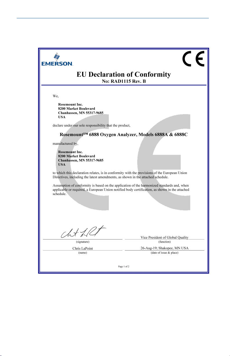
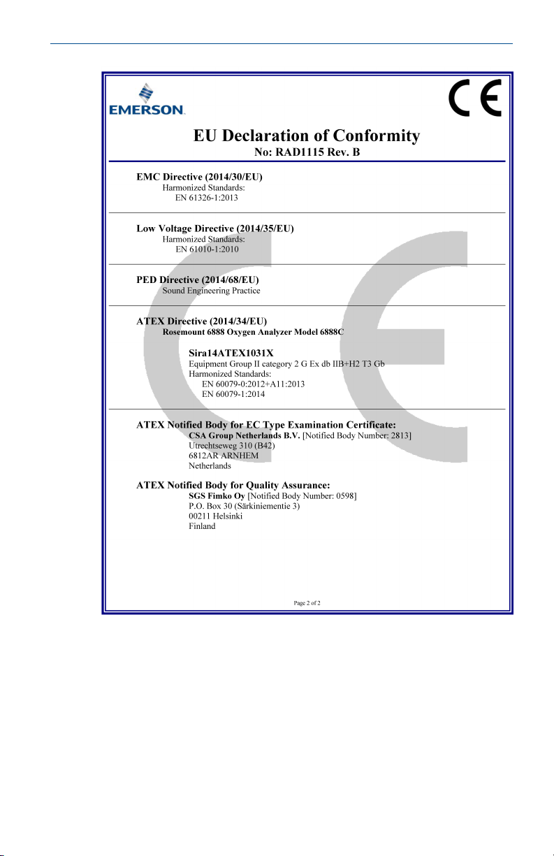
Declaration of Conformity..........................................................................................................36
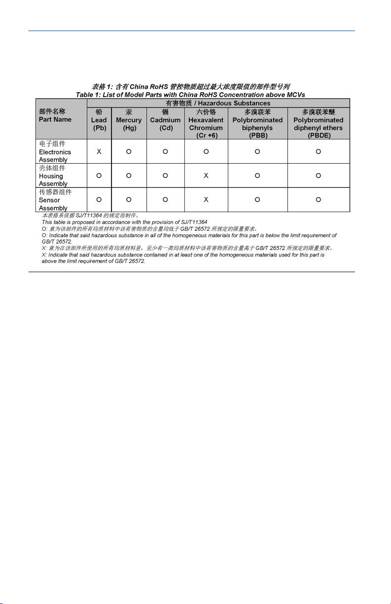
China RoHS Table....................................................................................................................... 38
Quick Start Guide 3
Page 4

Quick Start Guide October 2019
4 Emerson.com/Rosemount
Page 5

October 2019 Quick Start Guide
1 Install
WARNING
Failure to follow safety instructions could result in serious injury or death.
Before installing this equipment, read the Essential Instructions at the front
of this document.
WARNING
Electrical shock
Failure to install covers and ground leads could result in serious injury or
death.
Install all protective covers and ground leads after installation.
WARNING
Hazardous areas
The transmitter can be installed in general purpose areas only.
Do not install the transmitter in hazardous areas or in the vicinity of
flammable liquids.
CAUTION
Equipment damage
If external loop power is used, the power supply must be a safety extra low
voltage (SELV) type.
Quick Start Guide 5
Page 6

Quick Start Guide October 2019
1.1 Install probe
Most combustion processes run only slightly negative or positive in pressure,
so that the probe flange is for mechanical mounting only. The probe is not
rated for high pressures. If this is a new installation, a weld plate for welding
to the flue gas duct can be supplied.
WARNING
Electrical shock
Failure to install covers and ground leads could result in serious injury or
death.
Install all protective covers and ground leads after installation.
WARNING
Hazardous areas
The transmitter can be installed in general purpose areas only.
Do not install the transmitter in hazardous areas or in the vicinity of
flammable liquids.
Procedure
1. Ensure all components are available to install the probe.
If using the optional ceramic or Hastelloy diffusion element, make
sure to orient the vee deflector correctly.
2. Before inserting the probe, check the direction of gas flow in the
duct. Orient the vee deflector so the apex points upstream toward
the flow.
See Figure 1-1.
6 Emerson.com/Rosemount
Page 7

October 2019 Quick Start Guide
Figure 1-1: Orienting the Optional Vee Deflector
A. Gas flow direction
B. Vee deflector
C. Diffusion element
D. Setscrew
E. Vee deflector
F. Filter
G. Apex
3. If using the standard square weld plate or an optional flange
mounting plate, weld or bolt the plate onto the duct.
The through hole diameter in the stack or duct wall and refractory
material must be at least 2½-in. (63.5 mm).
Quick Start Guide 7
Page 8

Quick Start Guide October 2019
Figure 1-2: Rosemount 6888A Probe with Standard
Terminations/Electronic Housing
Note
All dimensions are in inches with millimeters in parentheses.
Figure 1-3: Rosemount 6888A Integral Autocal Housing
A. Dimension (see Table 1-1)
B. Dimension (see Table 1-1)
C. Hastelloy diffuser
D. Ceramic diffuser
Note
All dimensions are in inches with millimeters in parentheses.
8 Emerson.com/Rosemount
Page 9

October 2019 Quick Start Guide
Figure 1-4: Rosemount 6888A Integral Autocal Housing Close-up
A. Dimension (see Table 1-1)
B. Dimension (see Table 1-1)
C. Calibration gas ¼ tube fittings 5.0 SCFH (2.4 L/min) 20 psi (138
kPa)
D. #10 socket head cap screw (external ground)
E. ½ NPT conduit connection (power, signal)
F. Reference gas ¼ tube fitting 2.0 SCFH (1.0 L/min) 20 psi (138
kPa)
G. Reference air vents
Note
All dimensions are in inches with millimeters in parentheses.
Table 1-1: Removal/Installation
Probe length
18 in. (457 mm)
probe
3 ft. (0.91 m) probe 33.52 in. (826 mm) 46.6 in. (1182 mm) 50.1 in. (1271 mm)
6 ft. (1.83 m) probe 68.52 in. (1740 mm) 82.6 in. (2097 mm) 86.1 in. (2186 mm)
Quick Start Guide 9
(1)
Dim A insertion
depth
16.1 in. (409 mm) 15.77 in. (401 mm) 19.26 in. (490 mm)
Dim B removal
envelope standard
housing
Dim B removal
envelope accessory
housing
Page 10

Quick Start Guide October 2019
Table 1-1: Removal/Installation (continued)
Probe length
9 ft. (2.74 m) probe 104.52 in. (2655 mm) 118.6 in. (3011 mm) 122.1 in. (3100 mm)
12 ft. (3.66 m) probe 140.52 in. (3569 mm) 154.6 in. (3926 mm) 158.1 in. (4015 mm)
(1) Add 3.8 in. (96 mm) to Dim A and Dim B for probe with ceramic or Hastelloy diffuser.
(1)
Dim A insertion
depth
Dim B removal
envelope standard
housing
Dim B removal
envelope accessory
housing
The through hole diameter in the stack or duct wall and refractory
material must be at least 63.5 mm (2½ in.)
4. Insert probe through the opening in the mounting flange and bolt
the unit to the flange.
10 Emerson.com/Rosemount
Page 11

October 2019 Quick Start Guide
Figure 1-5: Probe Installation
A. Dimension (see Table 1-3)
B. Dimension (see Table 1-3)
C. Dimension (see Table 1-3)
D. Four studs, lockwashers, and nuts equally spaced on C dia. B C
Table 1-2: Mounting flange
ANSI DIN
Flange diameter 7.28 in. (185 mm)
Hole diameter .75 in. (20 mm)
(4) holes eq sp on BC 4.75 in. (121 mm) 5.71 in. (145 mm)
Table 1-3: Installation Weld Plate Outline
Dimension ANSI DIN
A 152 in. (600 mm) 191 in. (750 mm)
Quick Start Guide 11
Page 12

Quick Start Guide October 2019
Table 1-3: Installation Weld Plate Outline (continued)
Dimension ANSI DIN
B thread 11 in. (62.5 mm) M16x2
C diameter 121 in. (475 mm) 145 in. (579 mm)
Figure 1-6: Drip Loop and Insulation Removal
A. Line voltage
B. Logic I/O, 4-20 mA signal
C. Stack or duct metal wall
D. Adapter plate
E. Insulation
F. Note
Replace insulation after installing Rosemount 6888A
Note
Standard housing probe shown. Accessory housing is similar. Probe
installation may be vertical or horizontal.
12 Emerson.com/Rosemount
Page 13

October 2019 Quick Start Guide
1.2 Electrical installation
All wiring must conform to local and national codes. Multiple wiring
diagrams are shown in this section. Always refer to the diagrams that apply
to your transmitter configuration and disregard all other wiring diagrams.
WARNING
Electrical shock
Failure to install covers and ground leads could result in serious injury or
death.
Disconnect and lock out power before connecting the power supply.
Install all protective covers and ground leads after installation.
To meet the safety requirements of IEC 61010-1 (EC requirement) and
ensure safe operation of this equipment, connect the main electrical
power supply through a circuit breaker (min 10 A) which will disconnect
all current-carrying conductors during a fault situation.
This circuit breaker should also include a mechanically operated isolating
switch. If it does not, keep another external means of disconnecting the
power supply from the equipment located close by. Circuit breaks or
switches must complay with a recognized standard such as IEC 947.
To maintain proper earth grounding, ensure a positive connection exists
between the transmitter housing and earth. The connecting ground wire
must be 14 AWG minimum.
Line voltage, signal, and relay wiring should be rated for at least 221 °F
(105 °C).
1.2.1 Wire Rosemount 6888 Transmitter probe only (no Rosemount 6888 Xi Electronics)
The Rosemount 6888 transmitter probe has electronics in the blue housing
that controls the heater temperature and also amplifies the raw O2 millivolt
signal to a linear 4-20 mA. You can run the 4-20 mA signal lines directly to
the control room and also power the transmitter electronics. There is no O
display or keypad on the probe, so you must set up the transmitter through
HART® communications via a handheld communicator or via Asset
Management Solutions (AMS).
Procedure
1. Remove the cover from the probe.
2. Connect the line (L1 wire) to the L1 terminal, the netural (L2 wire) to
the L2/N terminal, and the ground wire to the ground lug.
The transmitter accepts 120/240 Vac ±10% line voltage and 50/60
Hz. No setup is required.
Quick Start Guide 13
2
Page 14
Quick Start Guide October 2019
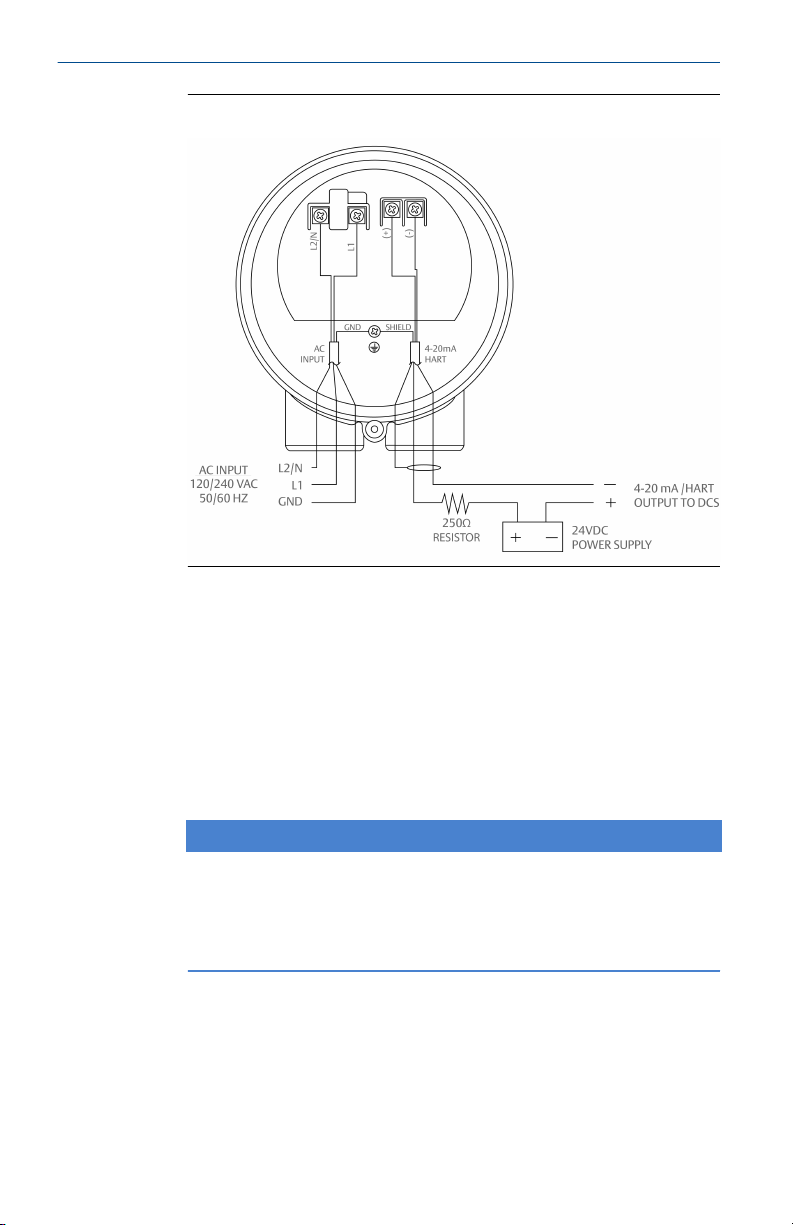
Figure 1-7: Rosemount 6888A Standard Probe Housing
3. Connect the 4-20 mA signal wires at the transmitter. Use a shielded
twisted wire pair.
Do not allow bare shield wires to contact the circuit boards. Insulate
the shield wires prior to termination. The transmitter electronics are
loop-powered, i.e., the 4-20 mA signal wires supply 24 Vdc from the
DCS or an external power supply.
4. Terminate the shield only at the transmitter electronics housing
unless using a Rosemount 6888 Xi. When using the Rosemount 6888
Xi Advanced Electronics, terminate the shield at both ends.
NOTICE
The 4-20 mA signal represents the O2 value and also powers the
probe-mounted electronics. Superimposed on the 4-20 mA signal is
HART information accessible through a Field Communicator or AMS
software.
5. Reinstall cover on transmitter.
6. Follow the remaining electrical instructions only if the Rosemount
6888 Xi is included with your system configuration.
14 Emerson.com/Rosemount
Page 15

October 2019 Quick Start Guide
1.2.2 Wire standard housing transmitter probe plus Rosemount™ 6888 Xi Electronics
The Rosemount 6888 Xi Electronics serve as an operator interface unit with a
back-lit display and keypad. It is capable of two channels, serving two
Rosemount 6888 probes.
Procedure
1. Remove cover screws from the front cover of the Rosemount 6888
Xi. Swing down the front cover of the interface box.
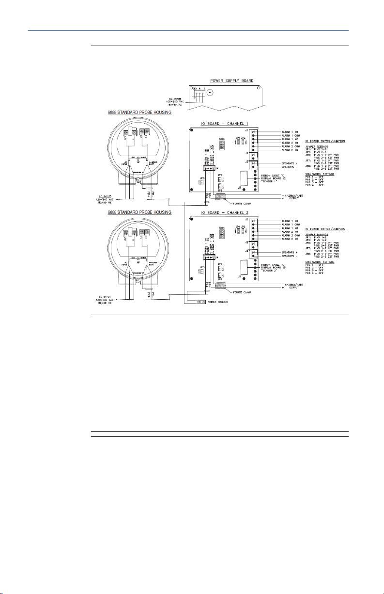
2. Pull out the I/O board on the right side of the card rack inside the
Rosemount 6888Xi.
If your system is configured to operate two transmitter probes, there
are two I/O interface boards. See Figure 1-8.
Quick Start Guide 15
Page 16
Quick Start Guide October 2019
Figure 1-8: Wiring Diagrams - Single/Dual Channel Wiring
Diagram
Note
A. Except for JP5, JP2, and JP8 on IO board, jumper and switch
settings are factory set and are shown for reference only.
B. IO board 4-20 mA/HART loop power settings:
JP5: Pins 1-2 internal power Rosemount 6888Xi to Rosemount
6888 transmitter, pins 2-3 external power Rosemount 6888Xi to
Rosemount 6888 transmitter (requires 2500 resistor across J4, PR
+ to PR-)
JP7/JP8: Pins 1-2 internal power Rosemount 6888Xi to DCS, pins
2-3 external power Rosemount 6888Xi to DCS.
16 Emerson.com/Rosemount
Page 17
October 2019 Quick Start Guide
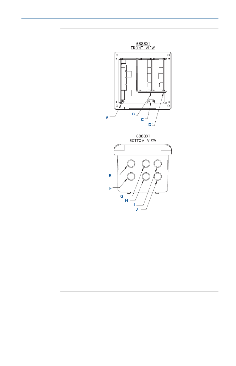
Figure 1-9: Rosemount 6888 Xi Front and Bottom View
A. Power supply board
B. Channel #2 IO board
C. Shield ground
D. Channel #1 IO board
E. AC input to P/S
F. Plug
G. Channel #2 alarm relay, SPS/IMPS
H. Channel #2 4-20 mA/HART® output
I. Channel #1 alarm relay SPS/IMPS
J. Channel #1 4-20 mA/HART output
3. Connect the 4-20 mA signal wires at J4 of the I/O board. Attach the
supplied ferrite clamp over the 4-20 mA out wires that extend past
the shield.
Quick Start Guide 17
Page 18

Quick Start Guide October 2019
NOTICE
Installation of the ferrite clamp over the 4-20 mA out wires is
required for the compliance with the European EMC directive.
4. Terminate the shield of the 4-20 mA signal wires at the designated
ground terminal of the Rosemount 6888 Xi. Do not allow bare shield
wires to contact the circuit boards. Insulate the shield wires prior to
termination.
5. Connect the signal wires from the Rosemount SPS or Rosemount
IMPS (if used) to the applicable terminals of J3.
Refer to the Rosemount SPS 4001B or Rosemount IMPS 4000
reference manual for wiring details.
6. Reinstall the I/O board in the card rack of the Rosemount 6888 Xi.
7. If your system is configured or two channel operation, repeat Step 2
through Step 6 to connect the other probe's signal wires.
8. Remove the probe's connector from the power supply board located
on the left side of the card rack inside the Rosemount 6888Xi.
9. Connect the line, or L1, wire to the L1 terminal and the neutral, or L2,
wire to the N terminal.
10. Reinstall the power supply connector in the power supply board.
1.2.3 Wire transmitter probe with integral autocal and HART
communications
You can initiate calibration via a calibration recommended diagnostic, time
since last calibration, manually via external dry contact, HART
communications, or from the Rosemount 6888 Xi local operator interface
keypad. You can only implement the integral autocal feature when using the
probe with the Rosemount 6888 Xi.
®
Procedure
1. Remove the two covers from the transmitter.
2. Connect the line (L1 wire) to the L1 terminal, the neutral (L2) wire to
the L2/N terminal, and the ground wire to the ground lug.
The Rosemount 6888A accepts line voltage at 120/240 Vac ±10%,
50/60 Hz. No setup is required.
3. Connect the 4-20 mA signal wires form the Rosemount 6888 Xi to
the connections in the side chamber of the transmitter.
Do not connect the signal wires to the terminals in the main chamber
where the AC input wires are connected. Use a shielded twisted wire
pair. Do not allow bare shield wires to contact the circuit boards.
18 Emerson.com/Rosemount
Page 19

October 2019 Quick Start Guide
Insulate the shield wires prior to termination. The 24 Vdc loop power
is sourced from the Rosemount 6888 Xi.
4. Terminate the shield at both the probe and the Rosemount 6888 Xi
Advanced Electronics.
NOTICE
The 4-20 mA signal represents the O2 value and also powers the
probe-mounted electronics. Superimposed on the 4-20 mA signal is
HART information accessible through a Field Communicator or AMS
software.
5. Reinstall both covers on transmitter.
6. Follow the remaining electrical installation instructions for the
Rosemount 6888 Xi included with your system configuration.
Quick Start Guide 19
Page 20
Quick Start Guide October 2019
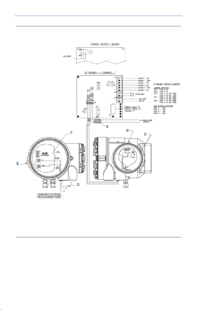
Figure 1-10: Integral Autocal and HART Communications
A. Ferrite clamp
B. Signal
C. Test points
D. #8 pan htd scr (internal ground)
E. Power
F. Test point group
Note
A. Except for JP5, JP7, and JP8 on IO board, jumper and switch settings are factory set and are
shown for reference only.
B. IO board: 4-20 mA/HART loop power settings
• JP5
20 Emerson.com/Rosemount
Page 21

October 2019 Quick Start Guide
— Pins 1-2: internal power Rosemount 6888 Xi to Rosemount 6888 transmitter
— Pins 2-5: external power Rosemount 6888 Xi to Rosemount 6888 transmitter
(requires 2,500 resistor across J4, PR+ to PR-)
• JP7/JP8
— Pins 1-2: internal power to DCS
— Pins 2-3: external power Rosemount 6888 Xi to DCS
Note
I/O board - Channel 2 is a duplicate of Channel 1.
See Figure 1-9 for the front and bottom view of the Rosemount 6888 Xi.
1.2.4 Wire transmitter probe with integral autocal and FOUNDATION
™
Fieldbus communications
This probe contains gas-switching solenoids so that the Rosemount™ 6888 Xi
electronics can control the introduction of calibration gases. You can initiate
calibrations manually via a calibration recommended diagnostic, time since
last calibration, external dry contact, FOUNDATION Fieldbus communications,
or from the Rosemount 6888 Xi local operator interface keypad. You can
only implement the integral autocal feature when using the probe with a
Rosemount 6888 Xi.
Procedure
1. Remove the two covers from the transmitter.
2. Connect the line (L1) wire to the L1 terminal, the neutral (L2) wire to
the L2/N terminal, and the ground wire to the ground lug.
The transmitter accepts 120/240 Vac ±10% line voltage and 50/60
Hz. No setup is required.
3. Connect the FOUNDATION Fieldbus wires from the Rosemount 6888
side housing to the FF segment.
The Rosemount 6888 probe is not rated as intrinsically safe and will
render any IS or FISCO segment it is wired to as non-IS. Use a shielded
twisted wire pair. Do not allow bare shield wires to contact the circuit
boards.
4. Terminate the shield at both the probe and the Rosemount 6888 Xi
Advanced Electronics.
Quick Start Guide 21
Page 22

Quick Start Guide October 2019
NOTICE
The FOUNDATION Fieldbus signal represents the O2 value and also
powers the probe-mounted electronics.
5. Reinstall both covers on transmitter.
6. Follow the remaining electrical installation instructions for the
Rosemount 6888 Xi included with your system configuration.
1.2.5 Connect traditional architecture system to the direct replacement probe
Use a traditional architecture configuration to provide for remote location of
the transmitter electronics. All electronics are housed inside the
Rosemount™ 6888 Xi. A multi-conductor power/signal cable connects the
probe to the Rosemount 6888 Xi. Use the following procedure to connect
the traditional architecture probe to the Rosemount 6888 Xi.
Note
The traditional architecture cable is provided at the specified length and is
ready for installation. The cable glands must be properly terminated to
maintain EMC/EMI noise protection.
Procedure
1. Run the 7-conductor cable between the traditional architecture
probe and the installation site for the Rosemount 6888 Xi.
Use new cable conduit or trough as needed.
2. Install the cable and lead wires to the probe per manufacturer's
instructions.
3. Install the cable at the probe housing and at the Rosemount 6888 Xi
enclosure.
a) Unscrew locking nut from gland assembly and slide locking
nut back along cable.
b) Pull the gland body away from the plastic insert.
Use care not to damage the cable shield braid.
c) Insert the cable wires into the proper entry port in either the
probe housing or the Rosemount 6888 Xi enclosure.
d) At the probe housing, apply Teflon tape or similar sealing
compound to the tapered pipe threads. Thread the gland
body into the probe housing until properly seated.
22 Emerson.com/Rosemount
Page 23

October 2019 Quick Start Guide
e) At the Rosemount 6888 Xi enclosure, insert the gland body
into the left front cable port from the inside of the enclosure.
Use the rubber O-ring provided to seal the cable port.
f) Ensure the cable shield braid is evenly formed over the gray
insert.
When properly formed, the braid should be evenly spaced
around the circumference of the insert and not extend
beyond the narrow diameter portion.
g) Carefully press the gray insert into the gland body.
The grooves on the insert should align with similar grooves
inside the gland body. Press the insert in until it bottoms out
in the gland body.
h) Slide the locking nut up and thread it onto the gland body.
Tighten the locking nut so the rubber grommet inside the
plastic insert compresses against the cable wall to provide an
environmental seal.
4. At the Rosemount 6888 Xi, connect the cable leads to the
connectors on the transmitter I/O board.
1.3 Pneumatic installation
1.3.1 Reference air package
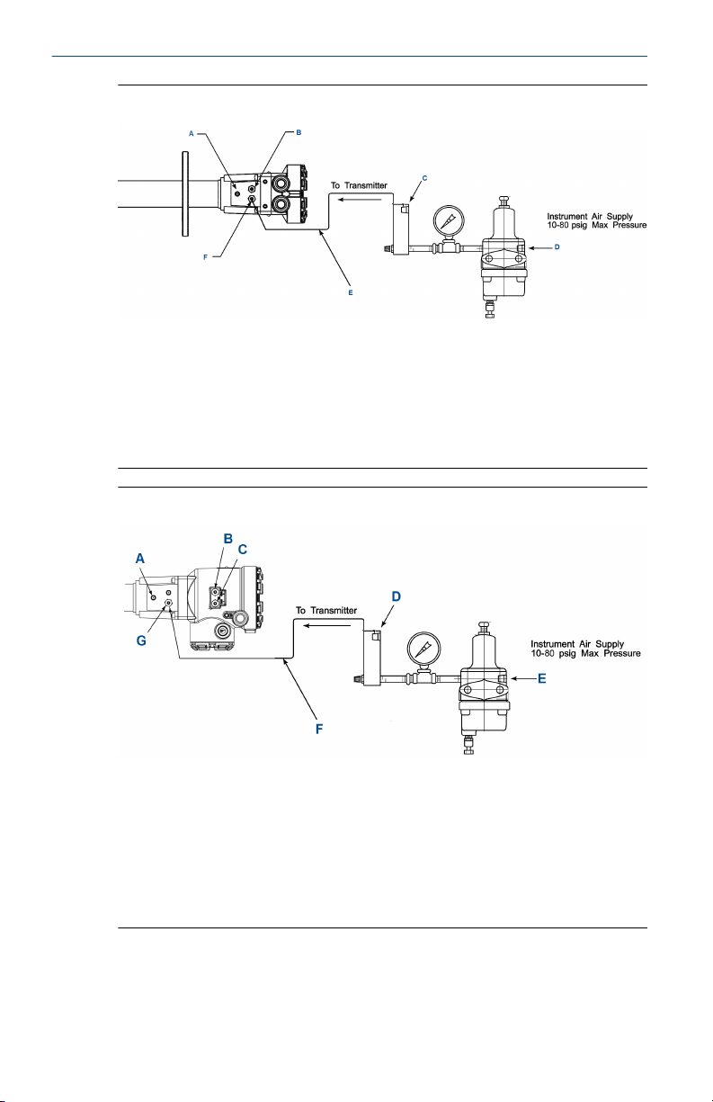
After the Rosemount™ 6888A is installed, connect the reference air set to the
transmitter unit.
Instrument air (reference air): 5 psi (34 kPa) minimum, 8 psi (54 kPa)
maximum at 2.0 scfh (1.01 L/min) maximum; less than 40 parts per million
total hydrocarbons. Set regulator outlet pressure at 5 psi (34 kPa).
Quick Start Guide 23
Page 24
Quick Start Guide October 2019
Figure 1-11: Plant Schematic Diagram, Standard Housing
A. Vent
B. Calibration gas: ¼-in. tube
C. Reference air flow meter
D. 0.25-18 national pipe thread (NPT) female inlet connection
E. 0.25 or 6 mm O.D. tubing (supplied by customer)
F. Reference gas: ¼-in. tube
Figure 1-12: Plant Air Schematic Diagram, Accessory Housing
A. Vent
B. Calibration gas 1: ¼-in. tube
C. Calibration gas 2: ¼-in. tube
D. Reference air flow meter
E. 0.25-18 NPT female inlet connection
F. 0.25 or 6 mm O.D. tubing (supplied by customer)
G. Reference gas: ¼-in. tube
24 Emerson.com/Rosemount
Page 25
October 2019 Quick Start Guide
1.3.2 Calibration gas
The transmitter uses two calibration gas concentrations, low gas - 0.4% O2,
balance N2, and high gas - 8% O2, balance N2.
CAUTION
Calibration reading errors
Failure to use proper gases will result in erroneous readings.
Do not use 100% nitrogen as a low gas (zero gas). Emerson suggests that
gas for the low (zero) be between 0.4% and 2.0% O2.
Do not use gases with hydrocarbon concentrations of more than 40
parts per million.
CAUTION
Equipment damage
If the ducts will be washed down during outage, verify that 6888A units have
been powered down and removed from the wash areas.
CAUTION
Equipment damage
Damage can result from having a cold unit exposed to the process gases.
Upon completing installation, ensure that the transmitter is turned on
and operating prior to firing up the combustion process.
During outages, if possible, leave all units running to prevent
condensation and premature aging from thermal cycling.
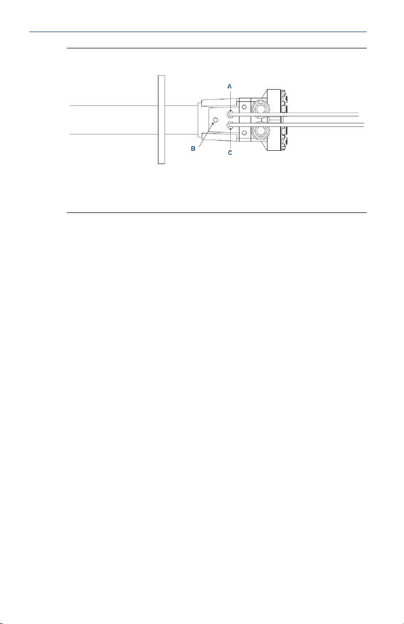
See Figure 1-13 for the calibration gas connections.
Quick Start Guide 25
Page 26
Quick Start Guide October 2019
Figure 1-13: Rosemount 6888A Calibration Gas Connections
A. Calibration gas in
B. Reference air vent
C. Reference air in
26 Emerson.com/Rosemount
Page 27
October 2019 Quick Start Guide
2 Configuration, startup, and operation
WARNING
Electrical shock
Failure to install covers and ground leads could result in serious injury or
death.
Install all protective covers and ground leads after installation.
CAUTION
Equipment damage
If external loop power is used, the power supply must be a safety extra low
voltage (SELV) type.
2.1 Power up transmitter without Rosemount™ 6888 Xi
Procedure
1. Apply AC line power to the transmitter.
2. Apply 24 Vdc loop power to the transmitter.
3. Using either the DCS control or a Field Communicator, verify
communications to the transmitter.
The transmitter probe takes approximately 45 minutes to warm up
to the 1357 °F (736 °C) heater setpoint. The 4-20 mA signal remains
at a default value of 3.5 mA, and the O2 reading remains at 0%
through this warm-up period. After warm-up, the probe begins
reading oxygen, and the 4-20 mA output is based on the default
range of 0-10% O2.
If there is an error condition at startup, an alarm message is
displayed.
2.2
Power up the Rosemount™ 6888 direct replacement probe (no electronics inside) with traditional architecture Rosemount 6888 Xi
Procedure
1. Apply AC line power to the Rosemount 6888 Xi.
2. Run the Quick Start Wizard as described in Run Rosemount™ 6888 Xi
Quick Start Wizard.
Quick Start Guide 27
Page 28

Quick Start Guide October 2019
3. At the Auto Cal Device screen, select None, SPS, or IMPS as
appropriate.
Do not select Integral or calibration will not be possible.
The transmitter probe takes approximately 45 minutes to warm up to the
736 °C (1357 °F) heater setpoint. The 4-20 mA signal remains at a default
value of 3.5 mA, and the O2 reading remains at 0% through this warm-up
period. After warm up, the probe begins reading oxygen, and the 4-20 mA
output is based on the default range of 0-10% O2.
If there is an error condition at startup, an alarm message is displayed on the
Rosemount 6888Xi.
2.3 Run Rosemount™ 6888 Xi Quick Start Wizard
When you first power up the Rosemount 6888 Xi, a short wizard program
guides you through the basic setup. Once configured, the Rosemount
6888Xi retains the setup, and the wizard will not repeat.
Procedure
1. Apply power to the Rosemount 6888 Xi.
Once boot-up is complete, the Quick Start Wizard screen appears.
With a dual channel Rosemount 6888 Xi, the wizard runs for both
channels in succession.
2. Press Enter to continue.
3. At the Sensor Type screen, use the Up and Down keys to select O2.
Do not select CO as this option is reserved for future use.
4. Press Enter to continue.
5. At the Device Type screen use the Up and Down keys to select
HART® or FF (FOUNDATION™ Fieldbus), whichever applies.
6. At the Auto Cal Device screen, use the Up and Down keys to select
the calibration method to be used. The methods are defined as
follows:
• None: Manual calibration with the standard probe housing
configuration.
• SPS: Automatic calibration with the standard probe housing
configuration using the Rosemount SPS 4001B.
• IMPS: Automatic calibration with the standard probe housing
configuration using the Rosemount IMPS.
• Integral: Automatic calibration with the integral autocal probe
housing configuration.
7. Press Enter to continue.
28 Emerson.com/Rosemount
Page 29

October 2019 Quick Start Guide
Note
If you select SPS, IMPS, or Integral, you must still configure automatic
calibration as On. Verify other parameters, such as test gas values
and gas times, as well. Refer to the Rosemount 6888 Xi Reference
Manual for calibration setup details.
8. When prompted by Setup Correct?, use the Up and Down keys
to select Yes.
If you select No, the wizard restarts.
9. Press Enter to continue.
The Rosemount 6888 Xi displays several screens while saving the
configuration, resets itself, and then returns to the main screen.
2.4 Calibration
2.4.1 Manual/semi-automatic calibration
A technician can calibrate the Rosemount 6888 probe with standard housing
by following prompts via the display of the Rosemount 6888 Xi Electronics
or via HART® communications to a Field Communicator or AMS console. The
technician needs to manually switch the gases based upon these prompts.
Emerson recommends using 0.4% O2 and 8% O2, balance nitrogen as
calibration gases. Always use a two-stage pressure regulator set to 20 psi.
Set the calibration gas flow meter for a maximum of 5 scfh with the cal gas
fitting removed from the probe. A diffuser/filter that is plugged over time
may cause the flow meter to deliver less flow to the sensing cell, but never
readjust the flow rate until a new diffuser is installed. Readjusting the flow
meter back up to the 5 scfh level could pressurize the cell during calibration
and cause the O2 reading to shift downwards.
The electronics determine if the calibration was successful and calculate new
calibration values. New calibration values are not automatically loaded into
the electronics after a successful calibration, however. The technician has
the opportunity to accept or reject the new values.
CAUTION
Reading errors
A loose or missing cap can permit fresh air to bias the O2 readings high in
processes that run at negative pressure.
Make sure the calibration gas port is capped tightly between calibrations.
2.4.2 Fully automatic calibration
For fully automatic calibration, the Rosemount™ 6888 Xi Electronics must
manage the actuation of solenoids to introduce gases into the probe.
Quick Start Guide 29
Page 30

Quick Start Guide October 2019
Calibrate probes with standard electronics housing
In addition to the Rosemount™ 6888 Xi, this arrangement requires a
separate single probe sequencer (SPS), which is a solenoid box for switching
calibration gases, or a larger intelligent multiprobe sequencer (IMPS), which
can handle the autocal for up to four probes in one box.
You can intiate automatic calibration in several ways:
• Via a calibration recommended diagnostic that is periodically checking cell
impedance.
• Via push button on the Rosemount 6888.Xi.
• Via HART® communications from a 475 handheld communicator or
AMS.
• Via an external contact closure.
• Via time since the last successful calibration.
The Rosemount 6888 Xi Electronics sequences the calibration gases in turn.
A 300 second flow time is the factory default for both gases and also for the
purge cycle, which lets the probe signal come back to the normal flue gas
readings. The 4-20 mA signal representing O2 can be held during the
calibration cycle or permitted to vary with the bottled gases, in which case a
record of the calibration can be trended at the DCS.
Calibrate probe with integral autocal housing
This probe contains the autocal solenoids within the blue electronics
housing, eliminating the need for a Rosemount™ SPS or IMPS solenoid
enclosure.
Note
The calibration sequence from the Rosemount 6888 Xi electronics will be
identical to that for manual/semiautomatic calibration, but with the integral
auto cal version of this probe it is not possible to conduct a manual
calibration.
Note
Calibration gas bottles are piped and under pressure at all times, so be sure
to leak-check all fittings, tubings, and connections. Always use dual-stage
pressure regulators.
2.4.3 Calibrate manually
This section covers manual calibration. For automatic calibration details, see
the reference manual for the Rosemount™ SPS 4001B Single Probe
30 Emerson.com/Rosemount
Page 31

October 2019 Quick Start Guide
Autocalibration Sequencer or the Rosemount IMPS 4000 Intelligent
Multiprobe Test Gas Sequencer.
Procedure
1. Use the Field Communicator to access the main HART® menu.
2. From the main menu, select CONFIGURE.
3. From the CONFIGURE menu, select CALIBRATION.
4. From the CALIBRATION menu, again select CALIBRATION.
5. From the CALIBRATION menu, select O2 CALIBRATION.
WARNING
Failure to remove the Rosemount 6888A from automatic control
loops prior to performing this procedure may result in a dangerous
operating condition.
In the first screen, a Loop should be removed from
automatic control warning occurs.
6. Remove the Rosemount 6888A from any automatic loop controls to
avoid a potentially dangerous operating condition. Press OK when
ready.
7. At the next screen, when the step shows APPLY GAS 1, press OK
to continue.
8. When Flow Gas 1 and Read Gas 1 are complete and the step shows
APPLY GAS 2, press OK to continue.
9. When Flow Gas 2 and Read Gas 2 are complete and the step shows
STOP GAS, press OK to continue the calibration with purge.
10. When the screen shows Loop may be returned to
automatic control, press OK to return to the CALIBRATION
screen.
11. At the CALIBRATION menu, select RESULT.
At the RESULT menu, the results of the calibration are displayed. In
the event the calibration cycle fails, the reason is displayed here as
well. The calibration results are described as follows:
• Success: Calibration completed successfully.
• Failed Constant: The calculated calibration constant is outside the
range of ±20.00.
• Failed Slope: The calculated calibration slope is outside the range
of 34.5 to 57.5.
Quick Start Guide 31
Page 32

Quick Start Guide October 2019
• WarmUp Abort: Attempted to perform a calibration during
warmup.
• Alarm Abort: Another alarm occurred and caused the calibration
cycle to abort.
12. In the event of a calibration failure, do the following:
a) From the RESULT menu, press HOME to return to the main
menu.
b) From the main menu, select SERVICE TOOLS.
c) From the OVERVIEW menu, select ALERTS.
d) Frpom the ALERTS menu, select ACTIVE ALERTS.
The ACTIVE ALERTS menu should contain an A:
CALIBRATION FAILED alarm.
e) Press the Left key to return to the ALERTS menu.
f) From the ALERTS menu, select DEVICE STATUS.
g) From the DEVICE STATUS menu, select ACKNOWLEDGE.
h) From the ACKNOWLEDGE menu, select ACK CALIBRATION
FAILED.
When the process is complete, the system returns to the
ACKNOWLEDGE menu.
32 Emerson.com/Rosemount
Page 33

October 2019 Quick Start Guide
3 Product certifications
Rev. 1.9
3.1 European Directive information
The most recent revision of the EU Declaration of Conformity can be found
at Emerson.com/Rosemount.
3.2 Ordinary location certification
As standard, the transmitter has been examined and tested to determine
that the design meets the basic electrical, mechanical, and fire protection
requirements by a nationally recognized test laboratory (NRTL) as accredited
by the Federal Occupational Safety and Health Administration (OSHA).
3.3 Installing equipment in North America
The US National Electrical Code® (NEC) and the Canadian Electrical Code
(CEC) permit the use of Division marked equipment in Zones and Zone
marked equipment in Divisions. The marking must be suitable for the area
classification, gas, and temperature class. This information is clearly defined
in the respective codes.
3.4 Rosemount™ 6888A In-Situ Oxygen Transmitter for General Purpose Locations
3.4.1 USA
FM Certificate
Standards
Markings
Special conditions for use
1. Type 4X and IP66 applies to the transmitter portion that is mounted
externally to the flue duct.
FM17NUS0009X
FM 3810:2005, ANSI/IEC-250:2003, ANSI/EC 60529:2004
Type 4X, IP66
3.4.2 Canada
CSA Certificate
Standards
Markings
Quick Start Guide 33
1913435
CAN/CSA C22.2 No. 61010-1-04, UL 61010-1:2004 (2nd
Edition), UL 50 (11th Ed.), IEC 60529 (Edition
2.1-2001-02), NEMA 250-2003
Type 4X, IP66
Page 34

Quick Start Guide October 2019
3.4.3 Europe
TUVRheinland QAL1
Certificate
Standards
MCERTS Certificate
Standards
0000038506
EN15267-1:2009, EN15627-2:2009,
EN15627-3:2007, EN14181:2004
Sira MC140270/00
EN15267-1:2009, EN15627-2:2009,
EN15627-3:2007, EN14181:2004
3.5 Rosemount™ 6888 Xi Digital Transmitter for General Purpose Locations
3.5.1 USA
FM Certificate
Standards
Markings
Special conditions for use
1. Mounting option 01 was not certified to provide Type 4X ingress
protection through the panel cut-out opening. The panel mount
gasket has not been tested for Type 4X installation.
3.5.2 Canada
FM17NUS0009X
FM 3810: 2005, ANSI/IEC: 2003, ANSI/EC 60529: 2004
Type 4X
CSA Certificate
Standards
Markings
1913435
CAN//CSA C22.2 No. 61010-1-04, UL 61010-1:2004 (2nd
Edition), CAN/CSA-C22.2 No.94-M91 (R2001), UL 50
(11th Ed.)
, Type 4X IP66
3.6 Rosemount™ SPS4001B and Rosemount IMPS4000 Autocalibration Devices for general purpose locations
3.6.1 USA/Canada
CSA certificate
Standards
34 Emerson.com/Rosemount
1640823
CAN/CSA C22.2 No. 61010-1-04; ANSI/UL 61010-1:2004,
(2nd Edition); CSA C22.2 No. 94.1-07; ANSI/UL 50 (12th
Edition); CSA C22.2 No. 94.2 (1st Edition); ANSI/UL 50 E
Page 35

October 2019 Quick Start Guide
First Edition; CSA C22.2 No. 60529:05 (R2010); ANSI/IEC
60529-2004 (R2011)
Markings
Type 4X, IP66
Quick Start Guide 35
Page 36
Quick Start Guide October 2019
A Declaration of Conformity
36 Emerson.com/Rosemount
Page 37
October 2019 Quick Start Guide
Quick Start Guide 37
Page 38
Quick Start Guide October 2019
B China RoHS Table
38 Emerson.com/Rosemount
Page 39

October 2019 Quick Start Guide
Quick Start Guide 39
Page 40

*00825-0100-4890*
00825-0100-4890, Rev. AB
Quick Start Guide
October 2019
GLOBAL HEADQUARTERS
Emerson Automation Solutions
6021 Innovation Blvd
Shakopee, MN 55379, USA
+1 800 999 9307 or +1 952 906 8888
+1 952 949 7001
[email protected]
EUROPE
Emerson Automation Solutions
Neuhofstrasse 19a P.O. Box 1046
CH-6340 Baar
Switzerland
+ 41 (0) 41 768 6111
+ 41 (0) 41 768 6300
[email protected]
Linkedin.com/company/Emerson-
Automation-Solutions
twitter.com/rosemount_news
Facebook.com/Rosemount
youtube.com/RosemountMeasurement
NORTH AMERICA
Rosemount
8200 Market Boulevard
Chanhassen, MN 55317
+1 800 999 9307
+1 952 949 7001
[email protected]
MIDDLE EAST AND AFRICA
Emerson Automation Solutions
Emerson FZE
Jebel Ali Free Zone
Dubai, United Arab Emirates, P.O. Box
17033
+971 4 811 8100
+971 4 886 5465
[email protected]
©
2019 Emerson. All rights reserved.
The Emerson logo is a trademark and service
mark of Emerson Electric Co. Rosemount is a
mark of one of the Emerson family of companies.
All other marks are the property of their
respective owners.
 Loading...