

Page 1

Quick Start Guide
00825-0200-4648, Rev EJ
March 2022
Rosemount™ 648 Wireless Temperature
Transmitter
with Rosemount X-well™ Technology
Page 2

Quick Start Guide March 2022
Rosemount 648 Wireless Temperature Transmitter
Rosemount 648 Hardware Revision 1
HART® Device Revision 4
Device Install Kit/DD Revision Revision 4, DD Revision 1 or higher
NOTICE
This guide provides basic information for the Rosemount 648 Wireless. It does not provide instructions
for detailed configuration, diagnostics, maintenance, service, troubleshooting, or installations. Refer
to the Rosemount 648 Wireless Reference Manual for more instruction. The manual and this guide are
also available electronically on Emerson.com/Rosemount.
WARNING
Failure to follow these installation guidelines could result in death or serious injury. Explosions could
result in death or serious injury.
Physical access
Unauthorized personnel may potentially cause significant damage to and/or misconfiguration of end
users’ equipment. This could be intentional or unintentional and needs to be protected against.
Physical security is an important part of any security program and fundamental to protecting your
system. Restrict physical access by unauthorized personnel to protect end users’ assets. This is true for
all systems used within the facility.
NOTICE
Shipping considerations for wireless products: (Lithium battery: Black Power Module, model number
701PBKKF). The unit was shipped to you without the Black Power Module installed. Remove the Black
Power Module prior to shipping the unit. Each Black Power Module contains two “C” size primary
lithium batteries. Primary lithium batteries are regulated in transportation by the U. S. Department of
Transportation, and are also covered by IATA (International Air Transport Association), ICAO
(International Civil Aviation Organization), and ARD (European Ground Transportation of Dangerous
Goods). It is the responsibility of the shipper to ensure compliance with these or any other local
requirements. Consult current regulations and requirements before shipping.
Contents
Wireless considerations................................................................................................................5
Physical installation...................................................................................................................... 8
Verify operation......................................................................................................................... 14
Reference Information............................................................................................................... 17
Power module replacement....................................................................................................... 20
Product certifications................................................................................................................. 22
2 Rosemount 648
Page 3

March 2022 Quick Start Guide
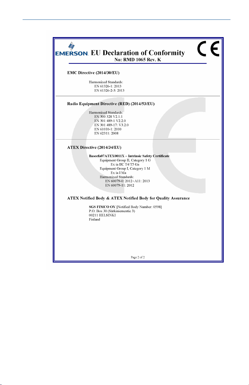
Declaration of Conformity..........................................................................................................30
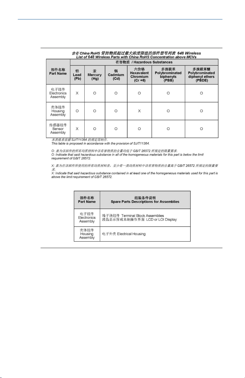
China RoHS................................................................................................................................ 32
Quick Start Guide 3
Page 4

Quick Start Guide March 2022
4 Rosemount 648
Page 5

March 2022 Quick Start Guide
1 Wireless considerations
1.1 Power up sequence
The Rosemount 648 Wireless and all other wireless devices should be
installed only after the Wireless Gateway (“Gateway”) has been installed and
is functioning properly. Wireless devices should also be powered up in order
of proximity from the Gateway, beginning with the closest. This will result in
a simpler and faster network installation. Enable active advertising on the
Gateway to ensure new devices join the network faster. For more
information, see the Wireless Gateway Reference Manual.
1.2 Antenna position
The antenna should be positioned vertically, either straight up or straight
down, and it should be approximately 3 ft. (1 m) from any large structure,
building, or conductive surface to allow for clear communication to other
devices.
Figure 1-1: Antenna Position
1.3 Conduit entry
Upon installation, ensure each conduit entry is either sealed with a conduit
plug using approved thread sealant, or has an installed conduit fitting or
cable gland with appropriate threaded sealant.
Quick Start Guide 5
Page 6

AA
Quick Start Guide March 2022
Note
The conduit entries are threaded ½–14 NPT.
Figure 1-2: Conduit Entry
A. Conduit entry
1.4 Field Communicator connections
The Black Power Module needs to be installed in the device for the Field
Communicator to interface with the Rosemount 648 Wireless. For HART
Wireless Transmitter communication via a Field Communicator, a
Rosemount 648 Wireless Device Dashboard (DD) is required. Rosemount
648 Wireless Transmitters equipped with Rosemount X-well Technology
requires DD revision 648 Dev. 4 Rev. 1 or higher to view Rosemount X-well
functionality. To obtain the latest DD, visit the Field Communicator System
Software and Device Description site at: Emerson.com/Field-Communicator.
Refer to Figure 1-3 for instructions on connecting the Field Communicator to
the Rosemount 648 Wireless Transmitter.
6 Rosemount 648
Page 7

COMM
P/N 00753-9200-0020
1
2
3
4
March 2022 Quick Start Guide
Figure 1-3: Connection
Quick Start Guide 7
Page 8

Quick Start Guide March 2022
2 Physical installation
2.1 Transmitter installation
The transmitter can be installed in one of two configurations:
• Direct Mount, where the sensor is connected directly to the Rosemount
648 Wireless housing’s conduit entry.
• Remote Mount, where the sensor is mounted separate from the
Rosemount 648 Wireless housing, then connected to the transmitter
using conduit.
Select the installation sequence that corresponds to the mounting
configuration.
2.2 Direct mount
The direct mount installation should not be used when installing with a
Swagelok® fitting.
Procedure
1. Install sensor according to standard installation practices using
approved thread sealant on all connections.
2. Attach transmitter housing to the sensor using the threaded conduit
entry.
3. Attach sensor wiring to the terminals as indicated on the wiring
diagram.
4. Connect Black Power Module.
Note
Wireless devices should be powered up in order of proximity from
the Wireless Gateway, beginning with the closest device to the
gateway. This will result in a simpler and faster network installation.
8 Rosemount 648
Page 9

March 2022 Quick Start Guide
Figure 2-1: Installing Electronics Housing Cover
5. Close housing cover and tighten to safety specification. Always
ensure a proper seal by installing the electronics housing covers so
metal touches metal, but do not over tighten.
6. Position antenna vertically, either straight up or straight down. The
antenna should be approximately 3 ft. (1 m) from any large
structures or buildings, to allow clear communication to other
devices.
Figure 2-2: Possible Antenna Rotation
2.3
Quick Start Guide 9
Remote mount
Procedure
1. Install sensor according to standard installation practices using an
approved thread sealant on all connections.
Page 10

Quick Start Guide March 2022
2. Run wiring (and conduit, if necessary) from the sensor to the
transmitter.
3. Pull wiring through the threaded conduit entry of the transmitter.
4. Attach sensor wiring to the terminals as indicated on the wiring
diagram.
5. Connect Black Power Module.
Note
Wireless devices should be powered up in order of proximity from
the wireless gateway, beginning with the closest device to the
Gateway. This will result in a simpler and faster network installation.
Figure 2-3: Installing Electronics Housing Cover
6. Close housing cover and tighten to safety specification. Always
ensure a proper seal by installing the electronics housing covers so
metal touches metal, but do not over tighten.
7. Position antenna vertically, either straight up or straight down.The
antenna should be approximately 3 ft. (1 m) from any large
structures or buildings to allow clear communication to other
devices.
10 Rosemount 648
Page 11

March 2022 Quick Start Guide
Figure 2-4: Possible Antenna Rotation
Quick Start Guide 11
Page 12
Quick Start Guide March 2022
2.4 Rosemount X-well Installation
Rosemount X-well Technology is only available in the Rosemount 648
Wireless and 0085 pipe clamp sensor factory assembled complete point
solution. Rosemount X-well Technology will only work as specified with
factory supplied and assembled pipe clamp sensor.
In general, pipe clamp sensor installation best practices shall be followed
(see Rosemount 0085 Pipe Clamp Sensor Reference Manual) with
Rosemount X-well Technology specific requirements noted below:
Procedure
1. Direct mounting of transmitter on pipe clamp sensor is required for
Rosemount X-well Technology to properly function.
2. Transmitter head shall be placed away from dynamic external
temperature sources such as a boiler.
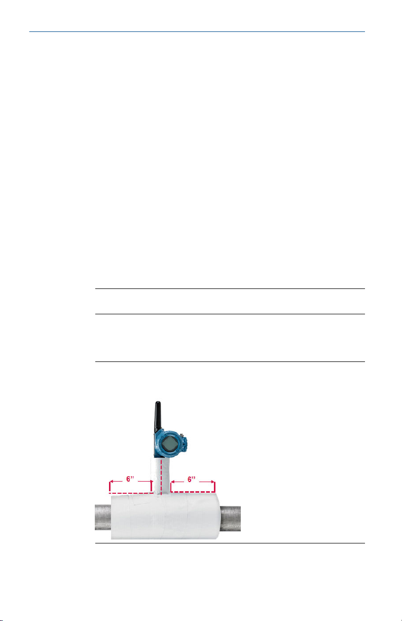
3. Insulation (½-in. thick minimum) is required over the sensor clamp
assembly and sensor extension up to transmitter head to prevent
heat loss. Apply a minimum of six inches of insulation on each side of
the pipe clamp sensor. Care should be taken to minimize air gaps
between insulation and pipe. See Figure 2-5.
Note
DO NOT apply insulation over transmitter head.
4. Although it will come factory configured as such, ensure that pipe
clamp RTD sensor is assembled in 3-wire configuration. See Figure
4-1 for more information.
Figure 2-5: Rosemount 648 Wireless with Rosemount X-well
Technology Installation Drawing
12 Rosemount 648
Page 13
A
B
C
March 2022 Quick Start Guide
2.5 LCD display
Transmitters ordered with the optional LCD display will be shipped with the
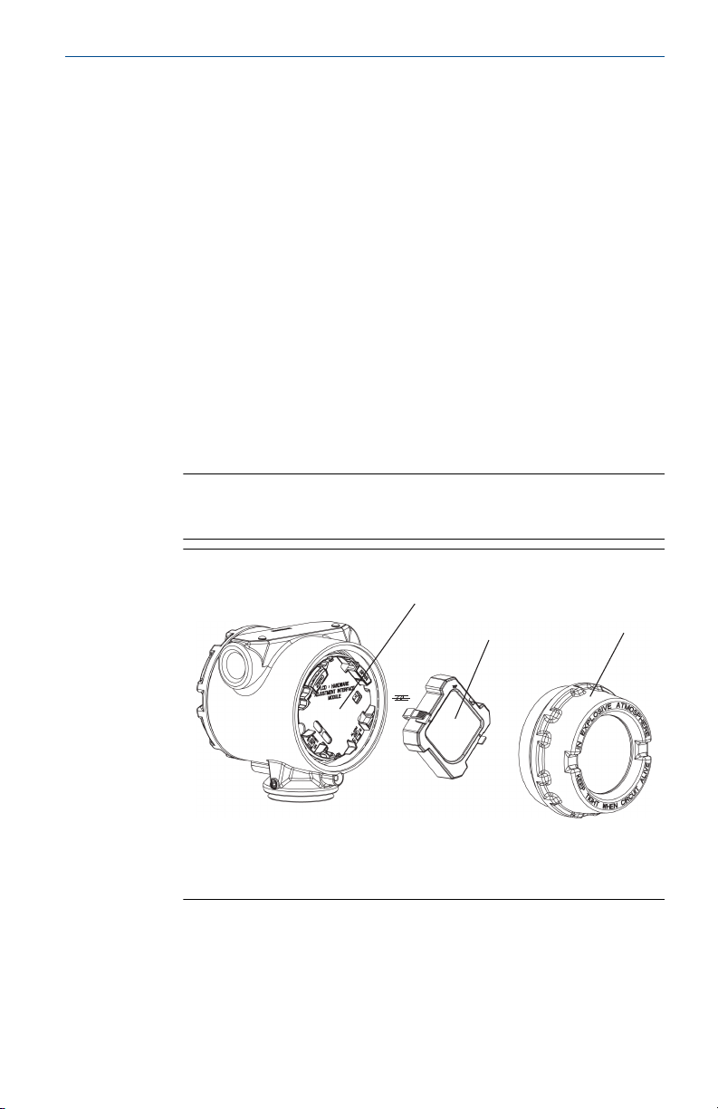
display installed. The LCD display can be rotated in 90 degree increments by
squeezing the two tabs, pulling out, rotating and snapping back into place. If
LCD display pins are inadvertently removed from the interface board,
carefully re-insert the pins before snapping the LCD display back into place.
Procedure
1. Remove the LCD display cover. Do not remove the instrument covers
in explosive environments when the circuit is live.
2. Put the 4-pin connector into the LCD display, rotate to the desired
position and snap into place.
3. Replace the transmitter cover.
The following LCD display temperature limits:
• Operating:–4 to 175 °F (–20 to 80 °C)
• Storage:–40 to 185 °F (–40 to 85 °C)
Note
Only use Rosemount Wireless LCD Display part number:
00753-9004-0002.
Figure 2-6: Optional LCD Display
A. LCD display pins
B. LCD display display
C. LCD display cover
Quick Start Guide 13
Page 14
n e t w k
A - s r c h
n e t w k
J O I N G
n e t w k
1 P A R N T
n e t w k
2 P A R N T
Quick Start Guide March 2022
3 Verify operation
3.1 Four methods of verification
Operation can be verified using four methods at the device via the LCD
display, using the Field Communicator, at the Gateway via the Wireless
Gateway’s integrated web server, or using AMS Wireless Suite or AMS Device
Manager.
LCD display
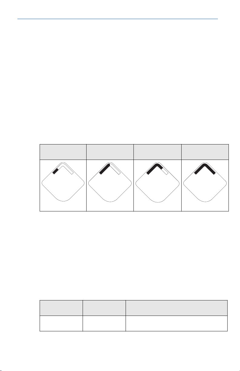
During normal operation, the LCD display will show the PV value at the
confirmed update rate. Refer to the Rosemount 648 Wireless Reference
Manual for error codes and other LCD display messages. Select the
Diagnostic button to display the TAG, Device ID, Network ID, Network Join
Status, and Device Status screens.
Searching for
network
Joining network Connected with
one parent
Connected with
two parents
Field Communicator
For HART Wireless transmitter communication via a Field Communicator, a
Rosemount 648 Wireless Device Dashboard (DD) is required. Rosemount
648 Wireless transmitters equipped with Rosemount X-well Technology
requires DD revision 648 Dev. 4 Rev. 1 or higher to view Rosemount X-well
functionality. To obtain the latest DD, visit the Field Communicator System
Software and Device Description site at: Emerson.com/Field-Communicator.
The communication status may be verified in the wireless device using the
following Fast Key sequence:
Table 3-1: Rosemount 648 Wireless Fast Key Sequence
Function Fast Key
sequence
Communications 3, 4 Comm, Join Mode, Neighbor Count,
Menu items
Advertisement Count, Join Attempts
14 Rosemount 648
Page 15
March 2022 Quick Start Guide
Wireless Gateway
If the Rosemount 648 Wireless was configured with the Network ID and Join
Key and sufficient time for network polling has passed, the transmitter will
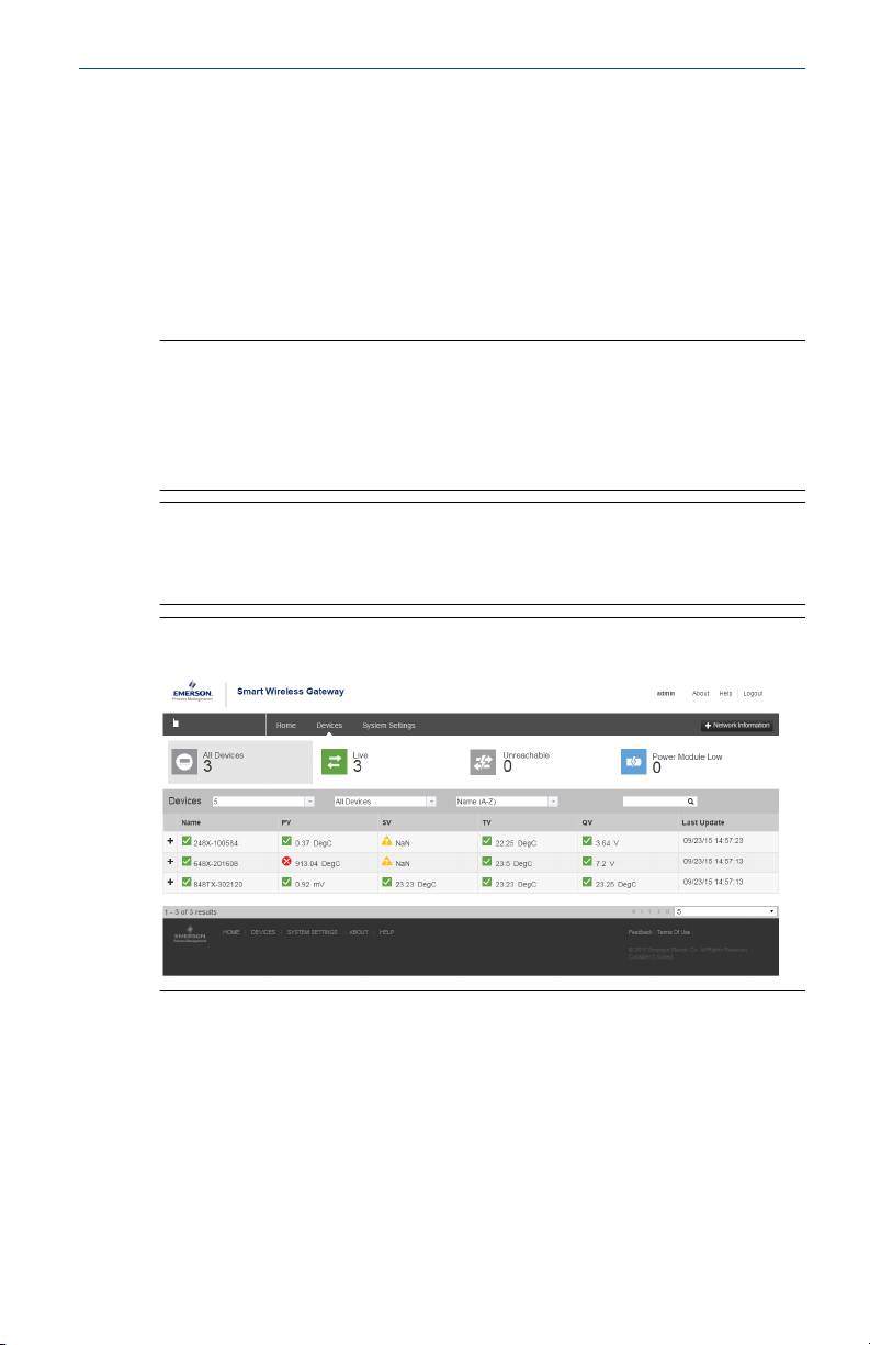
be connected to the network. To verify device operation and connectivity
using the Wireless Gateway's web based user interface, navigate to the
Devices page. This page will also display the transmitter's tag, PV, SV, TV,
QV, and Last Update time. Refer to Wireless Gateway User Interface Manual
Supplement for terms, user fields, and parameters used in the Wireless
Gateway web based user interface.
Note
The time to join the new device(s) to the network is dependent upon the
number of devices being joined and the number of devices in the current
network. For one device joining an existing network with multiple devices, it
may take up to five minutes. It may take up to 60 minutes for multiple new
devices to join the existing network.
Note
If the device joins the network and immediately has an alarm present, it is
likely due to sensor configuration. Check the sensor wiring (see Figure 4-1)
and the sensor configuration (see Table 1).
Figure 3-1: Wireless Gateway Network Settings
AMS Wireless Configurator
For HART Wireless transmitter communication via AMS Device Manager, a
Rosemount 648 Wireless Device Dashboard (DD) is required. Rosemount
648 Wireless Transmitters equipped with Rosemount X-well Technology
requires DD revision 648 Dev. 4 Rev. 1 or higher to view Rosemount X-well
functionality. To obtain the latest DD, visit the Emerson Easy Upgrade site at:
Emerson.com/Device-Install-Kits
Quick Start Guide 15
Page 16
Quick Start Guide March 2022
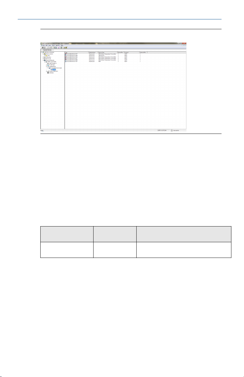
Figure 3-2: AMS Wireless Configurator Explorer Window
Troubleshooting
If the device is not joined to the network after power up, verify the correct
configuration of the network ID and join key, and verify that Active
Advertising has been enabled on the Wireless Gateway. The network ID and
join key in the device must match the network ID and join key of the
Gateway.
The network ID and join key may be obtained from the Wireless Gateway on
the Setup > Network > Settings page on the web server (see Figure 3-1). The
network ID and join key may be changed in the wireless device by using the
following Fast Key sequence.
Table 3-2: Wireless Configuration Fast Key Sequence
Function Fast Key
sequence
Wireless Configuration 2, 2, 1 Network ID, Join to Network, Broadcast
16 Rosemount 648
Menu items
Info
Page 17
1 2 3 4
1 2 3 4
1 2 3 4
1 2 3 4
2-wire
RTD and Ω
3-wire
RTD and Ω
4-wire
RTD and Ω
T/C and mV
March 2022 Quick Start Guide
4 Reference Information
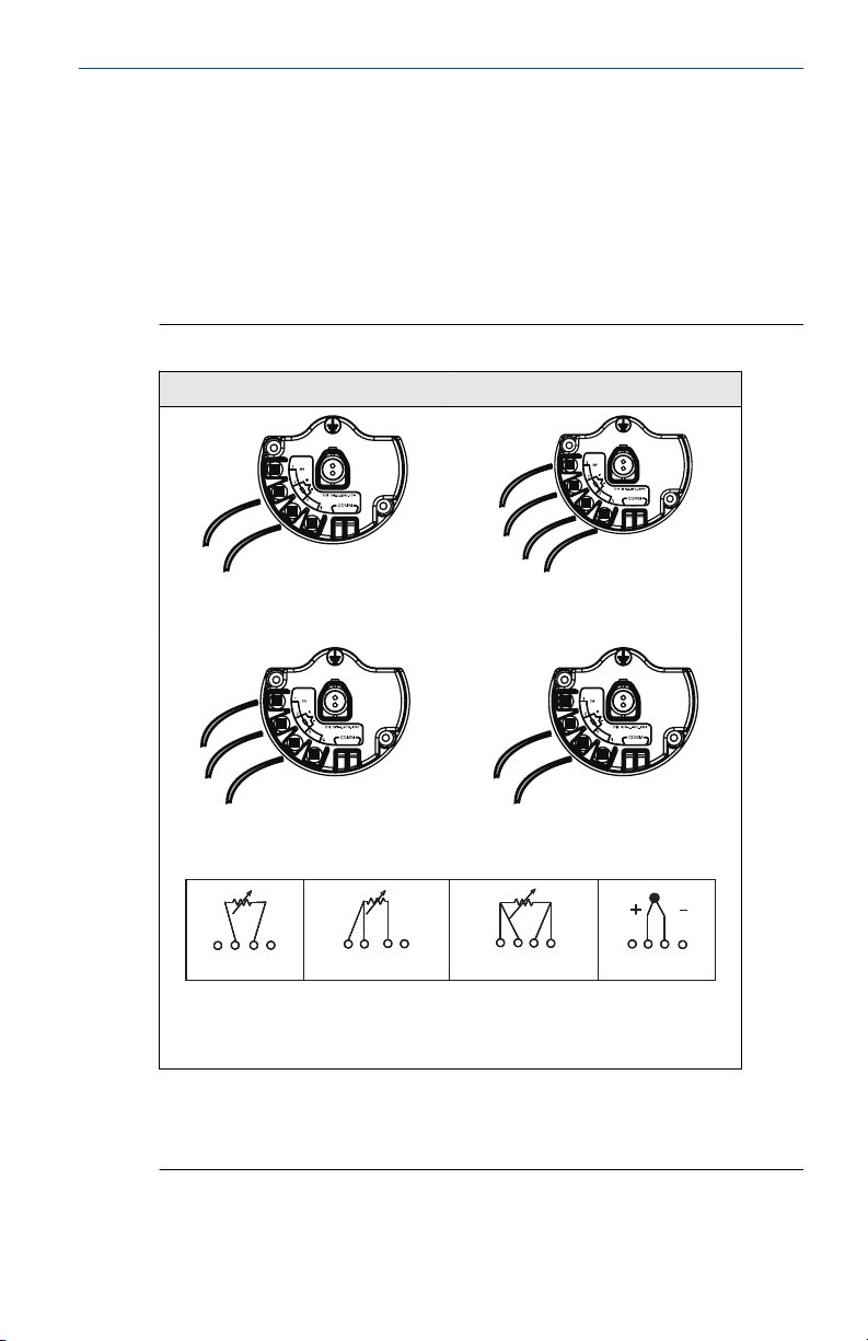
The Rosemount 648 Wireless is compatible with a number of RTD and
thermocouple sensor types.Figure 4-1 shows the correct input connections
to the sensor terminals on the transmitter. Figure 4-2, Figure 4-3, and Figure
4-4 show the lead wire configurations for Rosemount sensors. To ensure
proper sensor connection, anchor the sensor lead wires into the appropriate
compression terminals and tighten the screws.
Figure 4-1: Sensor Wiring
Thermocouple/mV 4-wire RTD and Ω
3-wire RTD and Ω 2-wire RTD and Ω
Quick Start Guide 17
Rosemount 648 Wireless Sensor connections diagram
Emerson provides 4-wire sensors for all single element RTDs. Use these RTDs
in 3-wire configurations by leaving the unneeded leads disconnected and
insulated with electrical tape.
Page 18
White (1)
White (2)
Red (3)
Red (4)
+ White (2)
– Red (3)
+ Purple (2)
– Red (3)
+ Yellow (2)
– Red (3)
+ Blue (2)
– Red (3)
+ Black (2)
– White (3)
+ Pink (2)
– White (3)
+ Green (2)
– White (3)
Quick Start Guide March 2022
Note
In order to communicate with a Field Communicator, the device must be
powered by connecting the black power module.
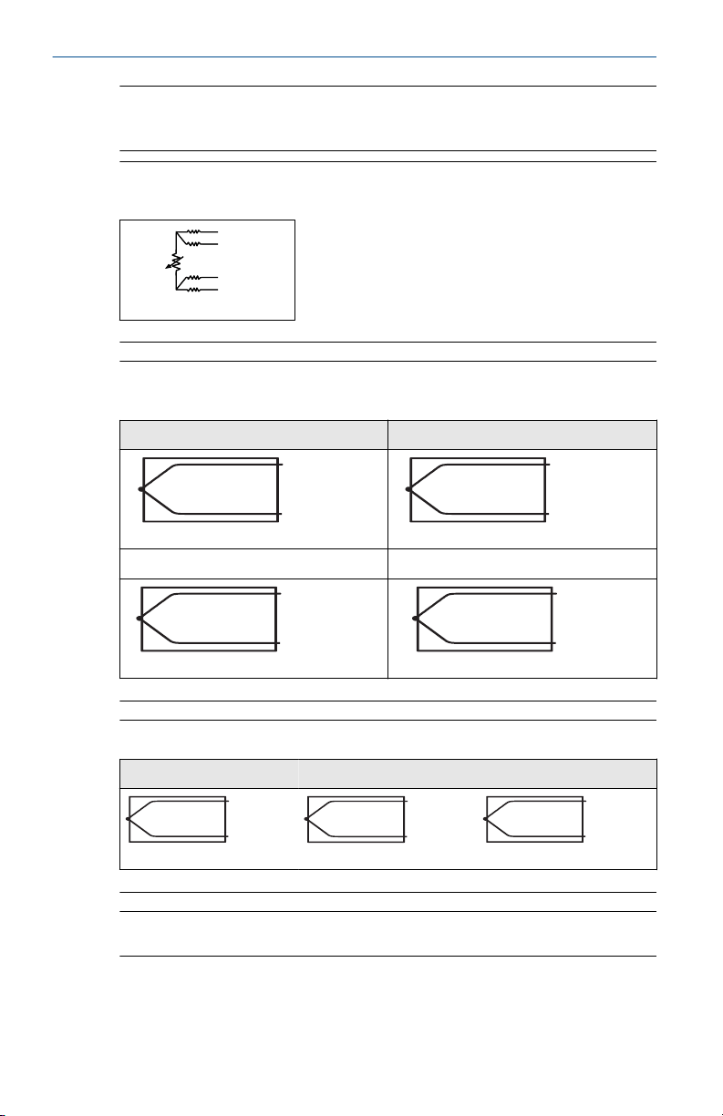
Figure 4-2: Single Element Rosemount 65, 68, 78 Series, and 58C Lead
Wire Configurations
Figure 4-3: Rosemount 183 Series Thermocouple Lead Wire
Configurations
Type J Type E
Type K Type T
Figure 4-4: Series 185 Thermocouple Lead Wire Configurations
Type J
Type N Type K
Note
The wiring diagrams shown above apply only to Rosemount sensors.
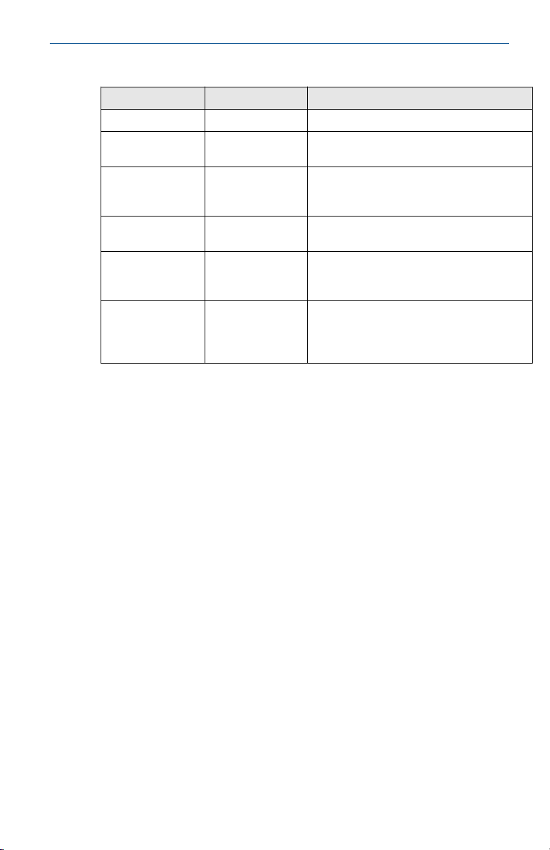
Table 4-1 lists the Fast Key sequences for common transmitter functions.
18 Rosemount 648
Page 19
March 2022 Quick Start Guide
Table 4-1: Rosemount 648 Wireless Fast Key Sequence
Function Fast Key sequence Menu items
Device Information 2, 2, 7 Tag, Long Tag, Descriptor, Message, Date
Guided Setup 2, 1 Configure Sensor, Join to Network, Config
Manual Setup 2, 2 Wireless, Sensor, Display, HART, Device
Wireless
Configuration
Sensor
Configuration
Sensor Calibration 3, 5, 2 Sensor Value, Sensor Status, Current Lower
2, 2, 1 Network ID, Join to Network, Broadcast Info
2, 2, 2, 5 Type, Connection, Units, Serial Number,
Advance Broadcasting, Calibrate Sensor
Temperature, Terminal Temp, Device
Information, Power, Security
Transmitter-Sensor Matching, RMT X-well
Setup
Trim, Current Upper Trim, RTD 2 Wire Offset,
Lower Sensor Trim, Upper Sensor Trim,
Device variable trim reset
Quick Start Guide 19
Page 20

Quick Start Guide March 2022
5 Power module replacement
Expected black power module life is 10 years at reference conditions.
When module replacement is required perform the following procedure.
5.1 Replace the power module
Procedure
1. Remove the cover and module.
2. Replace the module (part number 701PBKKF) and cover.
3. Tighten to specification and verify operation.
5.2 Handling considerations
The Black Power Module with the wireless unit contains two “C” size primary
lithium-thionyl chloride battery (Black Power Module, model number
701PBKKF). Each battery contains approximately 5.0 grams of lithium.
Under normal conditions, the battery materials are self-contained and are
not reactive as long as the batteries and the pack integrity are maintained.
Care should be taken to prevent thermal, electrical, or mechanical damage.
Contacts should be protected to prevent premature discharge.
Black Power Module should be stored in a clean and dry area. For maximum
Black Power Module life, storage temperature should not exceed 86 °F (30
°C).
Note
Continuous exposure to ambient temperature limits of –40 °F or 185 °F (–40
°C or 85 °C) may reduce specified life by less than 20 percent.
(1)
Use caution when handling the Black Power Module, it may be damaged if
dropped from heights in excess of 20 ft.
Battery hazards remain when cells are discharged.
5.3
20 Rosemount 648
Environmental considerations
As with any battery, local environmental rules and regulations should be
consulted for proper management of spent batteries. If no specific
requirements exist, recycling through a qualified recycler is encouraged.
Consult the materials safety data sheet for battery specific information.
(1)
Reference conditions are 70 °F (21° C), transmit rate of once per minute, and routing
data for three additional network devices.
Page 21

March 2022 Quick Start Guide
5.4 Shipping considerations
The unit was shipped to you without the Black Power Module installed.
Remove the module prior to shipping the unit.
Quick Start Guide 21
Page 22

Quick Start Guide March 2022
6 Product certifications
Rev 3.10
6.1 European Directive Information
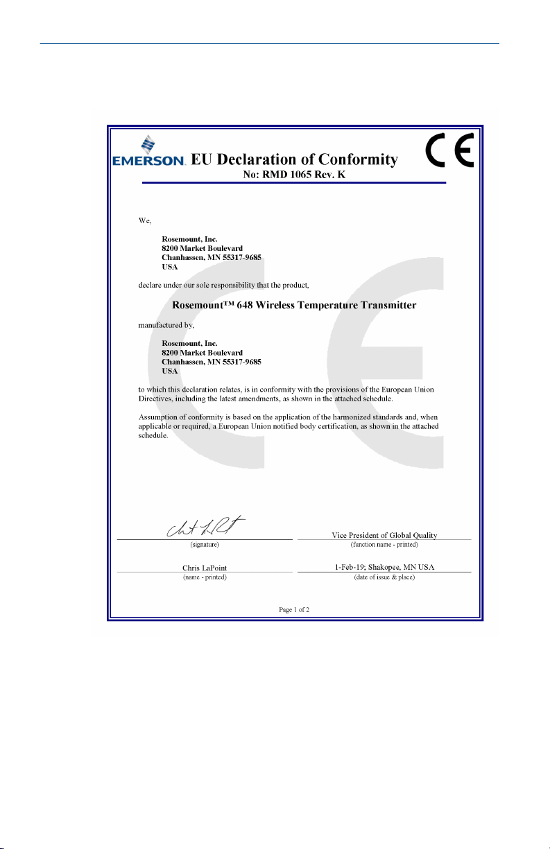
A copy of the EU Declaration of Conformity can be found at the end of the
Quick Start Guide. The most recent revision of the EU Declaration of
Conformity can be found at Emerson.com/Rosemount.
6.2 Telecommunication Compliance
All wireless devices require certification to ensure they adhere to regulations
regarding the use of the RF spectrum. Nearly every country requires this type
of product certification.
Emerson is working with governmental agencies around the world to supply
fully compliant products and remove the risk of violating country directives
or laws governing wireless device usage.
6.3 FCC and IC
This device complies with Part 15 of the FCC Rules. Operation is subject to
the following conditions: This device may not cause harmful interference.
This device must accept any interference received, including interference
that may cause undesired operation. This device must be installed to ensure
a minimum antenna separation distance of 20 cm from all persons.
6.4
6.5
6.6
Ordinary Location Certification
As standard, the transmitter has been examined and tested to determine
that the design meets the basic electrical, mechanical, and fire protection
requirements by a nationally recognized test laboratory (NRTL) as accredited
by the Federal Occupational Safety and Health Administration (OSHA).
North America
The US National Electrical Code® (NEC) and the Canadian Electrical Code
(CEC) permit the use of Division marked equipment in Zones and Zone
marked equipment in Divisions. The markings must be suitable for the area
classification, gas, and temperature class. This information is clearly defined
in the respective codes.
USA
6.6.1 I5 U.S. Intrinsic Safety (IS), Nonincendive (NI), and Dust Ignitionproof (DIP)
Certificate
22 Rosemount 648
FM 18US0009X
Page 23
March 2022 Quick Start Guide
Standards
FM Class 3600 — 2011, FM Class 3610 — 2010, FM Class 3611
— 2004, FM Class 3810 — 2005, ANSI/NEMA® 250 — 2003,
ANSI/ISA-60079-0 — 2009, ANSI/ISA-60079-11 — 2009
Markings
IS CL I, DIV 1, GP A, B, C, D; CL II, DIV 1, GP E, F, G; Class III,
T4/T5; Class 1, Zone 0 AEx ia IIC T4/T5; T4(–50 °C ≤ Ta ≤ +70
°C), T5(–50 °C ≤ Ta ≤ +40 °C) when installed per Rosemount
drawing 00648-1000; NI CL I, DIV 2, GP A, B, C, D T4/T5; T4(–
50 °C ≤ Ta ≤ +70 °C), T5(–50 °C ≤ Ta ≤ +40 °C) when installed
per Rosemount drawing 00648-1000; DIP CL II, DIV 1, GP E, F,
G; CL III, T5;T5(–50 °C ≤ Ta ≤ +85 °C); Type 4X; IP66
Special Conditions for Safe Use (X):
1. The Rosemount 648 Transmitter housing contains aluminum and is
considered a potential risk of ignition by impact or friction. Care must
be taken into account during installation and use to prevent impact
and friction.
2. The surface resistivity of the antenna is greater than 1 GΩ . To avoid
electrostatic charge build-up, it must not be rubbed or cleaned with
solvents or dry cloth.
3. The Rosemount 648 Wireless Transmitter shall only be used with the
701PBKKF Rosemount SmartPower™ Battery Pack (P/N
00753-9220-0001), Computational Systems Inc Battery Pack (P/N
MHM-89004) or alternatively the Perpetuum Intelligent Power
Module Vibration Harvester (P/N IPM71008).
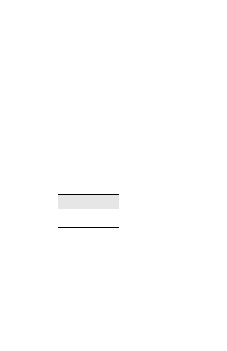
Sensor terminal
parameters
Uo = 6.6 V
Io = 26.2 mA
Po = 42.6 mW
Co = 23.8 μF
Lo = 50 mH
6.6.2 N5 U.S. Nonincendive (NI) and Dust Ignition-proof (DIP)
Certificate
Standards
Quick Start Guide 23
FM 3027705
FM Class 3600 — 2011, FM Class 3611 — 2004, FM Class 3810
— 2005, ANSI/NEMA 250 — 2003
Page 24
Quick Start Guide March 2022
Markings
NI CL I, DIV 2, GP A, B, C, D T4/T5; T4(–50 °C ≤ Ta ≤ +70 °C),
T5(–50 °C ≤ Ta ≤ +40 °C); DIP CL II, DIV 1, GP E, F, G; CL III, T5;
T5(–50 °C ≤ Ta ≤ +85 °C); Type 4X; IP66/67
Special Condition for Safe Use (X):
For use only with the Model 701PBKKF (P/N 753-9220-0001) Smart Power
Battery Module, Computational Systems Inc Battery Pack (P/N MHM-89004)
or alternatively the Perpetuum Intelligent Power Module Vibration Harvester
(P/N IPM71008).
6.7 Canada
6.7.1 I6 Canada Intrinsically Safe
Certificate
Standards
Markings
CSA 1143113
CAN/CSA C22.2 No. 0-10, CAN/CSA C22.2 No. 94-M91, CSA
Std C22.2 No. 142-M1987, CSA Std C22.2 No. 157-92, CSA
Std C22.2 No. 60529:05
Intrinsically Safe Class I, Division 1, Groups A, B, C and D T3C;
Class 1, Zone 0, IIC, T3C; when connected per Rosemount
drawing 00648-1020; Type 4X
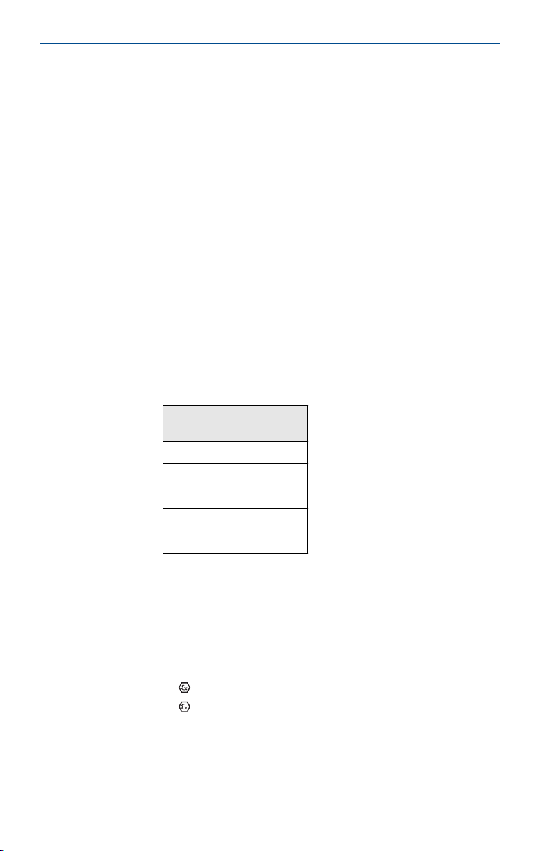
Sensor terminal
parameters
Uo = 6.6 V
Io = 26.2 mA
Po = 42.6 mW
Co = 23.8 μF
Lo = 50 mH
6.8 Europe
6.8.1 I1 ATEX Intrinsic Safety
Certificate:
Standards:
Markings:
For use with Rosemount SmartPower power module part number
753-9220-0001, or for use with Emerson SmartPower option 701PBKKF.
24 Rosemount 648
Baseefa07ATEX0011X
EN 60079-0: 2012 + A11:2013, EN 60079-11: 2012
II 1 G Ex ia IIC T4 Ga, T4(-60 °C ≤ Ta ≤ +70 °C)
II 1 G Ex ia IIC T5 Ga, T5(-60 °C ≤ Ta ≤ +40 °C)
Page 25
March 2022 Quick Start Guide
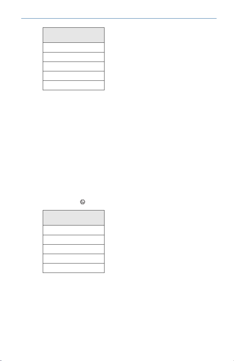
Sensor terminal
parameters
Uo = 6.6 V
Io = 26.2 mA
Po = 42.6 mW
Co = 11 μF
Lo = 25 mH
Special Conditions for Safe Use (X):
1. The surface resistivity of the antenna is greater than 1 GΩ. To avoid
electrostatic charge build-up, it must not be rubbed or cleaned with
solvents or dry cloth.
2. The power module may be replaced in a hazardous area. The power
module has a surface resistivity greater than 1 GΩ and must be
properly installed in the wireless device enclosure. Care must be
taken during transportation to and from the point of installation to
prevent electrostatic charge build-up.
6.8.2 NM ATEX Intrinsic Safety for Mining
Certificate:
Standards:
Markings:
Sensor terminal
parameters
Uo = 6.6 V
Io = 26.2 mA
Po = 42.6 mW
Co = 11 μF
Lo = 25 mH
Baseefa07ATEX0011X
EN 60079-0: 2012 + A11:2013, EN 60079-11: 2012
I M 1 Ex ia I Ma(-60 °C ≤ Ta ≤ +70 °C)
Special Conditions for Safe Use (X):
1. The surface resistivity of the antenna is greater than 1 GΩ. To avoid
electrostatic charge build-up, it must not be rubbed or cleaned with
solvents or dry cloth.
2. The power module may be replaced in a hazardous area. The power
module has a surface resistivity greater than 1 GΩ and must be
properly installed in the wireless device enclosure. Care must be
Quick Start Guide 25
Page 26
Quick Start Guide March 2022
taken during transportation to and from the point of installation to
prevent electrostatic charge build-up.
6.9 International
6.9.1 I7 IECEx Intrinsic Safety
Certificate
Standards
Markings
Special Conditions for Safe Use (X):
1. The surface resistivity of the antenna is greater than 1 GΩ . To avoid
electrostatic charge build-up, it must not be rubbed or cleaned with
solvents or dry cloth.
2. The Model 701PBKKF Power Module may be replaced in a hazardous
area. The Power Modules have a surface resistivity greater than 1 GΩ
and must be properly installed in the wireless device enclosure. Care
must be taken during transportation to and from the point of
installation to prevent electrostatic charge build-up.
IECEx BAS 07.0007X
IEC 60079-0: 2011, IEC 60079-11: 2011
Ex ia IIC T4 Ga, T4 (–60 °C ≤ Ta ≤ +70 °C)
Ex ia IIC T5 Ga, T5 (–60 °C ≤ Ta ≤ +40 °C)
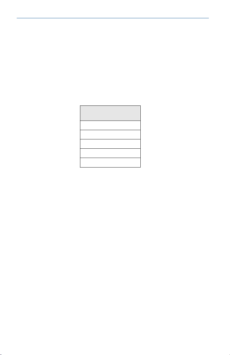
Sensor terminal
parameters
Uo = 6.6 V
Io = 26.2 mA
Po = 42.6 mW
Co = 11 μF
Lo = 25 mH
3. The Rosemount 648 enclosure may be made of aluminum alloy and
given a protective polyurethane paint finish; however, care should be
taken to protect it from impact or abrasion if located in a Zone 0
area.
6.10
Brazil
6.10.1 I2 Brazil Intrinsic Safety
Certificate
Standards
26 Rosemount 648
UL-BR 15.0140X
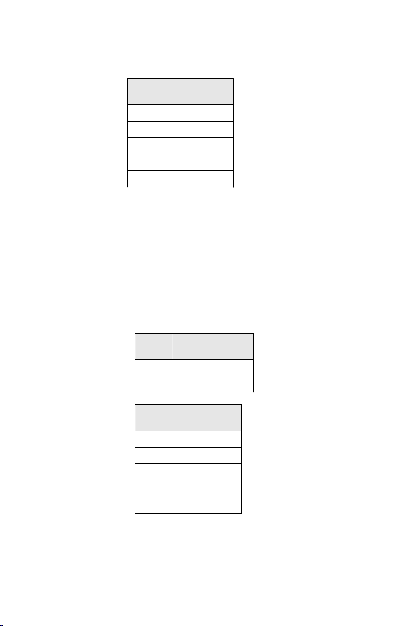
ABNT NBR IEC 60079-0:2013, ABNT NBR IEC 60079-11:2013
Page 27
March 2022 Quick Start Guide
Markings
Ex ia IIC T4 (–60 °C ≤ Ta ≤+70 °C), Ex ia IIC T5 (–60 °C ≤ Ta ≤ +40
°C); IP66
Sensor terminal
parameters
Uo = 6.6 V
Io = 26.2 mA
Po = 42.6 mW
Co= 11 μF
Lo = 25 mH
Special Condition for Safe Use (X):
See certificate for special conditions.
6.11 China
6.11.1 I3 China Intrinsic Safety
Certificate
Standards
Markings
GYJ21.3298X
GB3836.1-2010, GB3836.4-2010, GB3836.20-2010
Ex ia IIC T4/T5 Ga
T code Ambient
T4 -60 °C ≤ Ta ≤ +70 °C
T5 -60 °C ≤ Ta ≤ +40 °C
temperature
Sensor terminal
parameters
Uo = 6.6 V
Io = 26.2 mA
Po = 42.6 mW
Co = 11 μF
Lo = 25 mH
Special Condition for Safe Use (X):
See certificate for special conditions.
Quick Start Guide 27
Page 28
Quick Start Guide March 2022
6.12 Japan
6.12.1 I4 Japan Intrinsic Safety
Certificate
Markings
CML 18JPN2105X
Ex ia IIC T5/T4 Ga
See certificate for ambient temperature ranges.
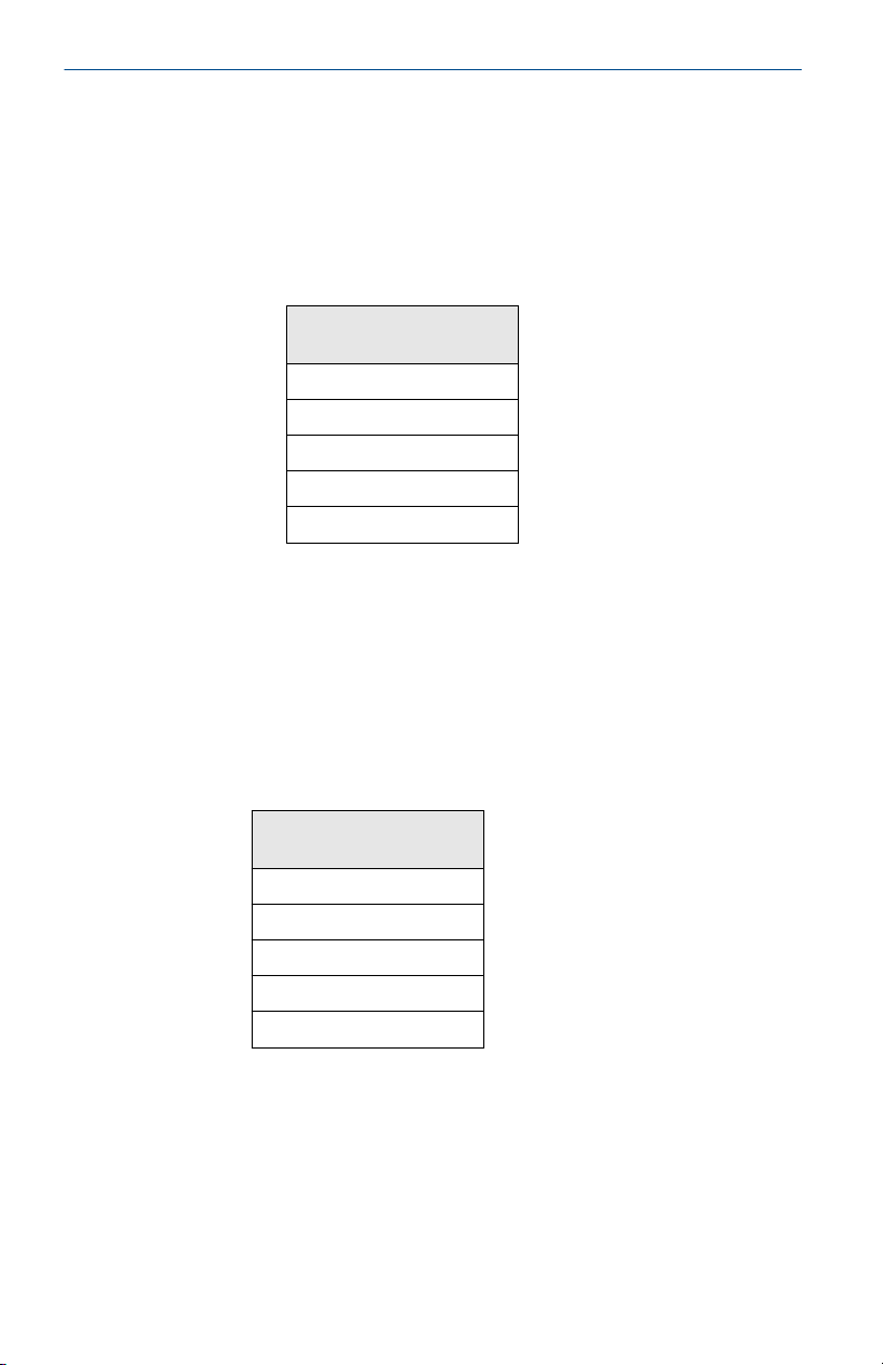
Sensor terminal
parameters
Uo = 6.6 V
Io = 26.2 mA
Po = 42.6 mW
Co = 11 μF
Lo = 25 mH
Special Condition for Safe Use (X):
See certificate for special conditions.
6.13 EAC - Belarus, Kazakhstan, Russia
6.13.1 IM Technical Regulation Customs Union Intrinsic Safety
Markings
0Ex ia IIC T4/T5 Ga X, T4 (–60 °C ≤ Ta ≤ +70 °C) T5 (–60 °C ≤ Ta ≤
+40 °C)
Sensor terminal
parameters
Uo = 6.6 V
Io = 26.2 mA
Po = 42.6 mW
Co = 11 μF
Lo = 25 mH
Special Condition for Safe Use (X):
See certificate for special conditions.
28 Rosemount 648
Page 29
March 2022 Quick Start Guide
6.14 Republic of Korea
6.14.1 IP Republic of Korea Intrinsic Safety
Certificate
Markings
11-KB4BO-0071
Ex ia IIC T4/T5 T4 (–60 °C ~ +70 °C) T5 (–60 °C ~ +40 °C)
Special Condition for Safe Use (X):
See certificate for special conditions.
6.15 Combination
KQ
Combination of I1, I5, and I6
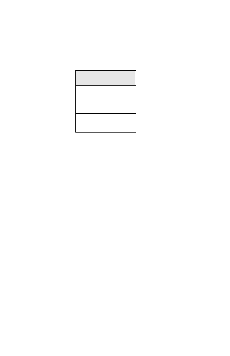
Sensor terminal
parameters
Uo = 6.6 V
Io = 26.2 mA
Po = 42.6 mW
Co = 10.9 μF
Lo = 25 mH
Quick Start Guide 29
Page 30
Quick Start Guide March 2022
7 Declaration of Conformity
30 Rosemount 648
Page 31
March 2022 Quick Start Guide
Quick Start Guide 31
Page 32
Quick Start Guide March 2022
8 China RoHS
32 Rosemount 648
Page 33

March 2022 Quick Start Guide
Quick Start Guide 33
Page 34

Quick Start Guide March 2022
34 Rosemount 648
Page 35

March 2022 Quick Start Guide
Quick Start Guide 35
Page 36

*00825-0200-4648*
Quick Start Guide
00825-0200-4648, Rev. EJ
March 2022
For more information:
©
2022 Emerson. All rights reserved.
Emerson Terms and Conditions of Sale are
available upon request. The Emerson logo
is a trademark and service mark of
Emerson Electric Co. Rosemount is a mark
of one of the Emerson family of
companies. All other marks are the
property of their respective owners.
Emerson.com
 Loading...