

Page 1
Product Data Sheet
December 2017
CMB-PDS-6888
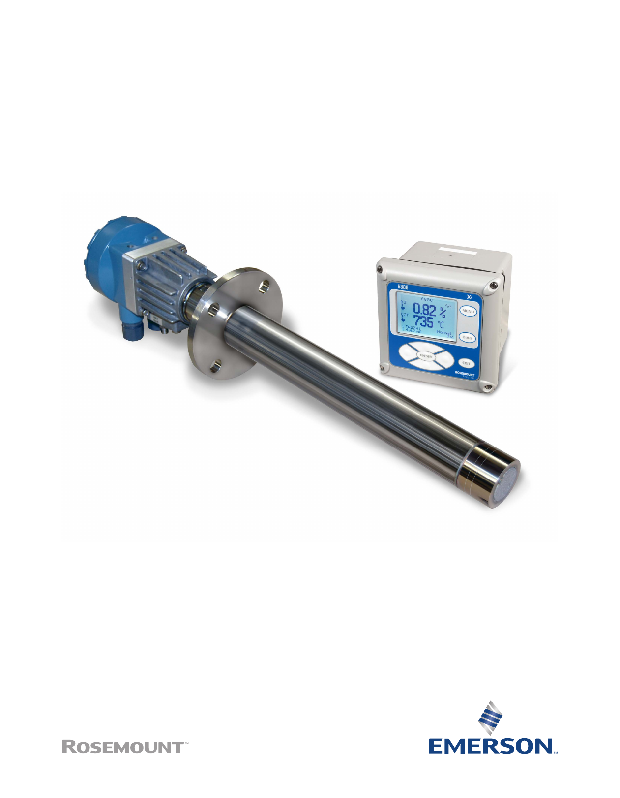
Rosemount™ 6888 In-Situ Oxygen Transmitter
The new standard for combustion flue gas analysis
The RosemountTM 6888 combustion ue gas transmitter provides a continuous, accurate measurement of the oxygen remaining
in ue gases coming from any combustion process. Accurate measurements of furnace exhaust excess oxygen are critical for
combustion optimization, resulting in reduced energy costs, increased safety, and lower emissions. Reduction of overall downtime
and maintenance can be achieved with the Rosemount 6888's robust oxygen sensor and autocalibration capabilities.
Page 2
Overview
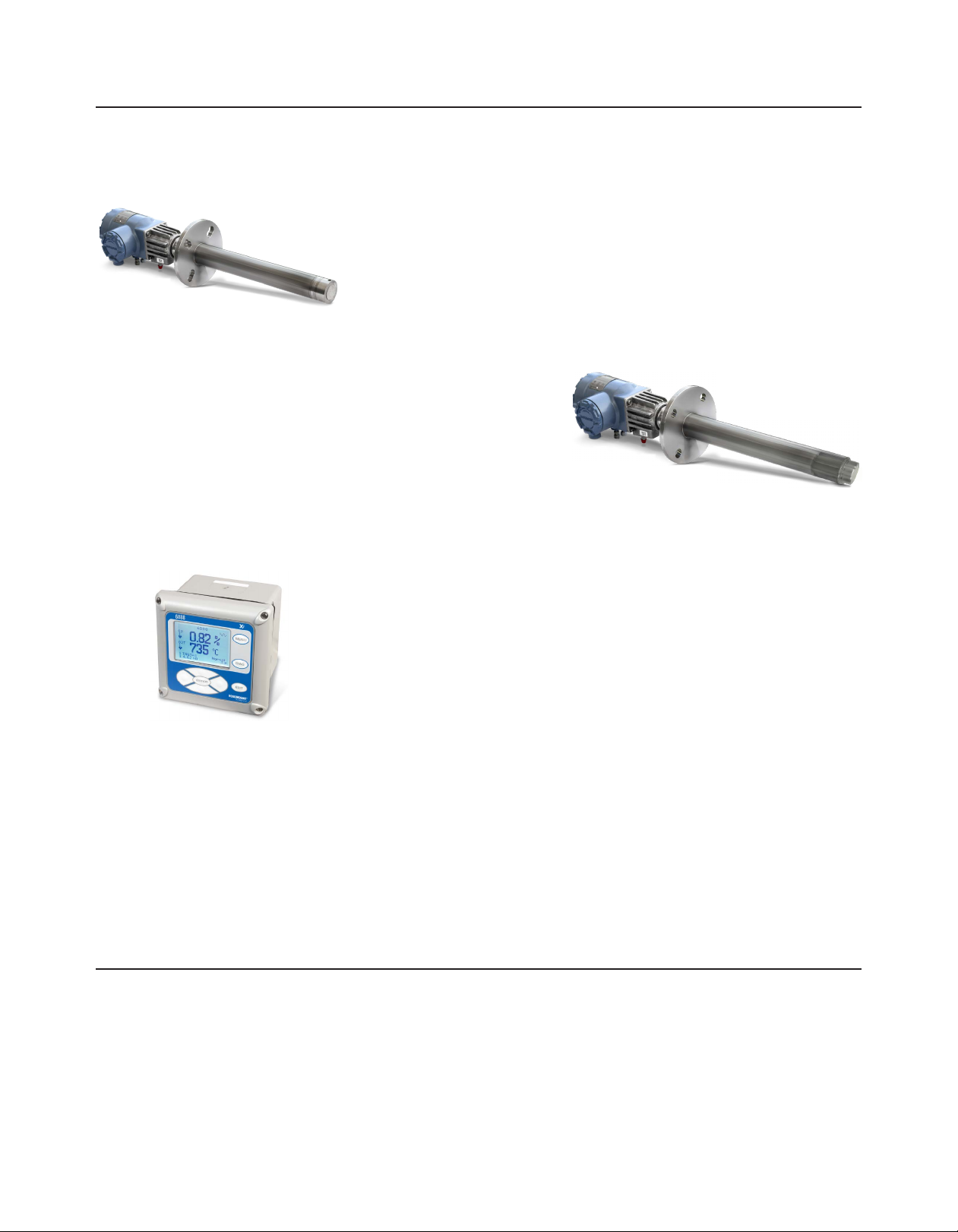
Proven performance and reliability
Robust zirconia oxygen sensing cell with catalytic platinized beads increases cell
lifetime in presence of sulfur and other poisoning agents.
Outstanding accuracy: ±0.75% of reading or ±0.05% O2.
Rugged explosion-proof design for hazardous area approvals satises ATEX/IECEX Ex d
and CSA Class 1, Division 1/Zone 1.
Advanced sensor diagnostics
Calibration recommended diagnostics.
Plugged diffuser/lter diagnostics.
Low oxygen diagnostics and O2 readings during reducing conditions.
Adaptability
Completely eld repairable and adaptable to nearly any existing O2 probe installation
(Westinghouse World Class, Rosemount Oxymitter, and most competitive O2 probe
installations).
Variable probe insertion options.
Contents
RosemountTM 6888A In-Situ Oxygen Transmitter for general
purpose locations ........................................................................3
RosemountTM 6888C In-Situ Oxygen Transmitter for hazardous
locations .....................................................................................6
RosemountTM SPS 4001B and Rosemount IMPS 4000
Autocalibration Devices for general purpose locations ...............10
2 3
2
How to order: Complete Oxygen Analysis system ............... 12
Specications ..................................................................... 13
RosemountTM 6888 product certications...........................16
Dimensions ........................................................................19
Accessories......................................................................... 27
www.Emerson.com/RosemountGasAnalysis
Page 3
December 2017 December 2017Rosemount 6888 Oxygen Transmitter Rosemount 6888 Oxygen Transmitter
RosemountTM 6888A In-Situ Oxygen Transmitter for
general purpose locations
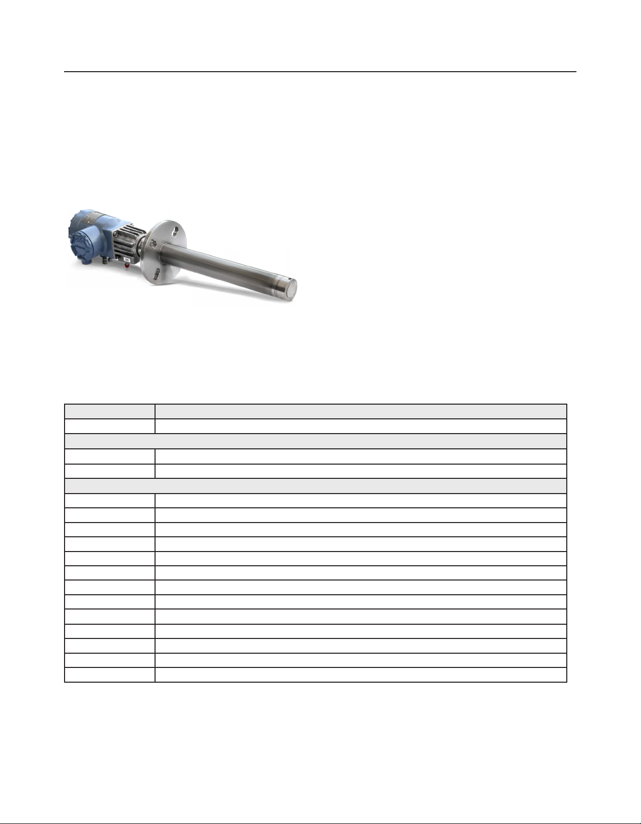
The RosemountTM 6888A combustion ue gas transmitter is a
solution for optimizing any industrial or large commercial boiler,
red heater, or kiln. The Rosemount 6888A, as part of an oxygen
trim system, improves plant energy efciency and lowers energy
costs. It not only meets application requirements but also is
simple to install, commission, and operate. The sensor, diffusers,
and accessories for the Rosemount 6888A were developed to
provide the greatest performance and longevity even in the
harshest of process conditions.
World-class performance and outstanding accuracy: ±0.75% of
reading or ±0.05% O
Digital communications: HART® 5 and Foundati onTM Fieldbus
Resilient sensing cells provide protection to sulfur and other
poisoning agents present in ue gas
Specication and selection of product materials, options, or components must be made by the purchaser of the equipment. See
page 13 for more information on material selection.
2
Table 1. Rosemount 6888A In-Situ Oxygen Transmitter for General Purpose Locations
Model Sensor type
6888A In-Situ Oxygen Transmitter
Measurement
1
1OXY
2
2OXY
Probe length and type/shield
1 18 in. (457 mm) standard probe tube
3
2
3 18 in. (457 mm) abrasion-resistant probe tube
4 3 ft (0.91 m) standard probe tube
3
5
6 3 ft (0.91 m) abrasion-resistant probe tube
7 6 ft (1.83 m) standard tube
3
8
9 6 ft (1.83 m) abrasion-resistant probe tube
3
A
AA 9 ft (2.74 m) probe with abrasive shield accessory package (mounting hardware included)
3
B
BA 12 ft (3.66 m) probe with abrasive shield accessory package (mounting hardware included)
Oxygen - standard sensing cell
Oxygen - acid resistant sensing cell
18 in. (457 mm) probe with abrasive shield accessory package (mounting hardware included)
3 ft (0.91 m) probe with abrasive shield accessory package (mounting hardware included)
6 ft (1.83 m) probe with abrasive shield accessory package (mounting hardware included)
9 ft (2.74 m) probe with abrasion-resistant probe body
12 ft (3.66 m) probe with abrasion-resistant probe body
www.Emerson.com/RosemountGasAnalysis
3
Page 4

Diffuser
1 Snubber diffuser for service to 400 °C (750 °F)
1A Snubber diffuser for service to 400 °C (750 °F) with dust seal for use with abrasive shield
1F Snubber diffuser for service to 400 °C (750 °F) with ashback arrestor
2 Ceramic diffuser for service to 825 °C (1517 °F)
2A Ceramic diffuser for service to 825 °C (1517 °F) with dust seal for use with absrasive shield
2F Ceramic diffuser for service to 825 °C (1517 °F) with ashback arrestor
3 Hastelloy diffuser for service to 705 °C (1300 °F)
3A Hastelloy diffuser for service to 705 °C (1300 °F) with dust seal for use with abrasive shield
Housing & electronics
1HT Standard housing, digital probe, HART protocol
2HT Integral autocalibration housing, digital probe, HART protocol
4FF Integral autocalibration housing, digital probe, Foundation Fieldbus protocol
5DR Standard housing, direct replacement probe, traditional architecture
6DRY Standard housing, direct replacement probe, with cold junction for YEW electronics
Mounting plate
00 No additional mounting hardware
04 New installation - square weld plate, ANSI: 6 x 6 in. (152.4 x 152.4 mm), 2.5 in. (63.5 mm) clearance hole, 4.75 in.
(120.65 mm) bolt circle, 5/8-11 studs
05 New installation - square weld plate, DIN 6 x 6 in. (152.4 x 152.4 mm), 2.5 in. (63.5 mm) clearance hole, 4.75 in.
(120.65 mm) bolt circle, 5/8-11 studs
06 New installation - variable insertion mount, abrasion-resistant probe only
07 New installation - variable insertion mount, mounted to existing OXT/WC abrasive shield mount; abrasion resistant probe only
08 Adapter plate for existing ANSI 3 in. (76.2 mm) 150# ange
09 Adapter plate for existing ANSI 4 in. (101.6 mm) 150# ange
10 Adapter plate for existing ANSI 6 in. (152.4 mm) 150# ange
11 Adapter plate for existing ANSI 3 in. (76.2 mm) 300# ange
12 Adapter plate for existing ANSI 4 in. (101.6 mm) 300# ange
99 Special adapter -provide existing ange dimensions, including thru-hole diameter
Manual calibration accessories
00 None
01 Calibration and reference gas owmeters and reference air lter regulator, provided loose
02 Calibration and reference gas owmeters and reference air lter regulator, mounted in a panel
Enable: Stochiometer indicator for reducing conditions
0 No
1 Yes
Enable: Programmable reference function
0 No
1 Yes
Enable: Extended temperature function
0 No
1 Yes
4
4
4
4 5
www.Emerson.com/RosemountGasAnalysis
Page 5

December 2017 December 2017Rosemount 6888 Oxygen Transmitter Rosemount 6888 Oxygen Transmitter
Enable: Diffuser warning
4
0 No
1 Yes
1. Standard sensing cell includes catalytic protection beads which protect the sensor from sulfur and other poisoning agents.
2. Acid-resistant sensing cell includes additional catalytic protection beads compared to standard sensing to protect the sensor from sulfur and other poisoning
agents.
3. Abrasive shield tube ordered separately.
4. Foundation Fieldbus versions only (for HART versions, order this feature with Rosemount Xi Electronics).
www.Emerson.com/RosemountGasAnalysis
Page 6
RosemountTM 6888C In-Situ Oxygen Transmitter for
hazardous locations
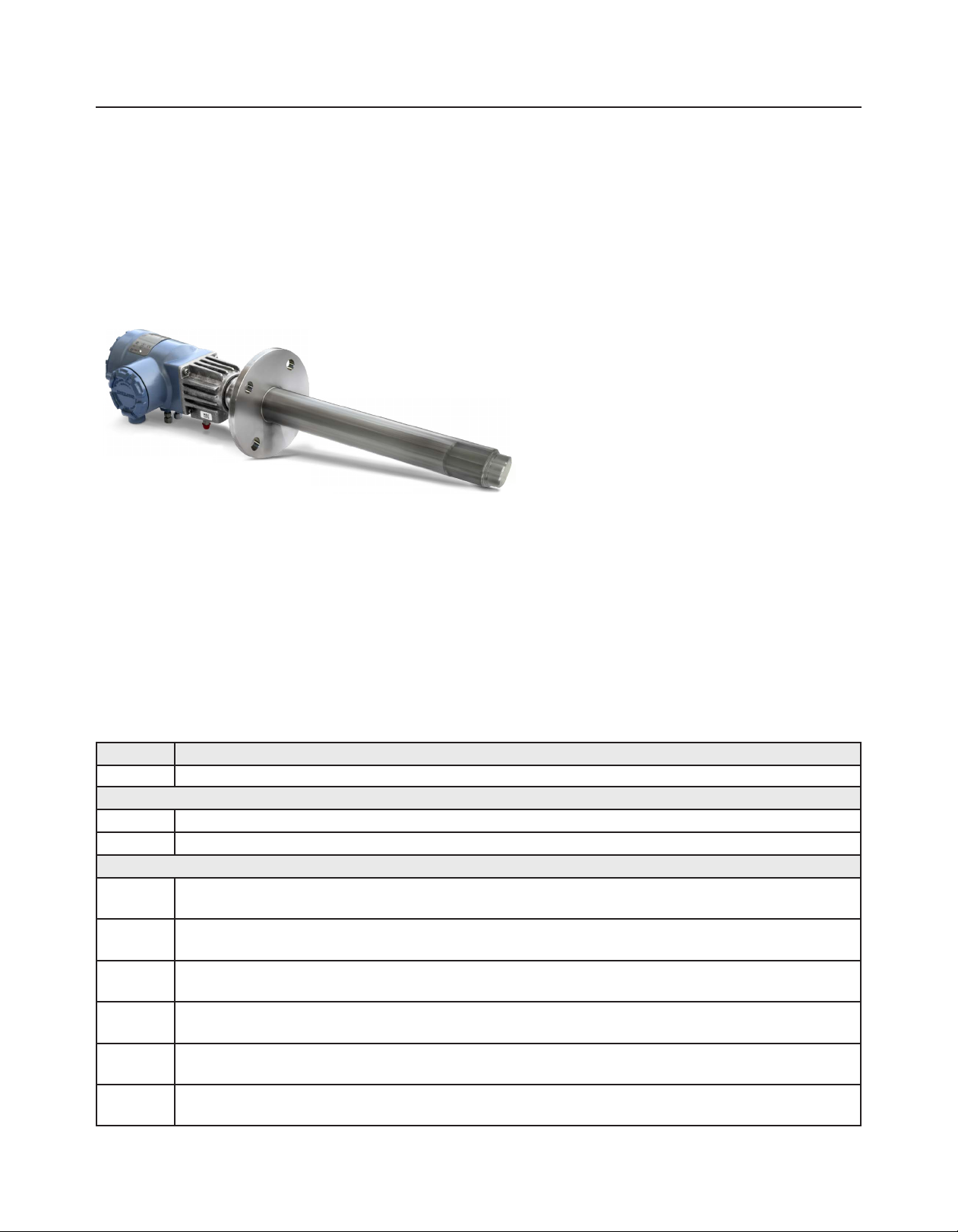
The RosemountTM 6888C combustion ue gas
transmitter is a solution for optimizing boilers or red
heaters located in areas with hazardous requirements.
The Rosemount 6888C's calibration equipment is
simplied in hazardous areas with the approved
integrated automatic calibration housing option.
Maintenance costs are reduced with the redesigned
modular diffuser and process ame arrestor assembly.
Rugged explosion-proof design satises ATEX/
IECEx Ex d and CSA Class 1, Division/Zone 1 approval
requirements.
Digital communications: HART® 5 standard,
FoundationTM Fieldbus, and AMS/PlantWeb
Resilient sensing cells provide protection to sulfur and
other poisoning agents present in ue gas.
Additional information
Specications can be found on page 13. Drawings are
provided on page 19.
®
Specication and selection of product materials, options, or components must be made by the purchaser of the equipment. See
page 13 for more information on material selection.
Table 2. Rosemount 6888C In-Situ Oxygen Transmitter for Hazardous Locations
Model Product description
6888C In-Situ Oxygen Transmitter for hazardous locations
Measurement
1OXY Oxygen - standard sensing cell
2OXY Oxygen - acid resistant sensing cell
Probe length and mounting flange
1A 18 in. (457 mm) probe with ANSI ange: 7.5 in (190.5 mm). O.D., 6.00 in. (152.4 mm) bolt hole pattern diameter, 0.75 in.
1D 18 in. (457 mm) probe with DIN ange: 8.25 in. (209.55 mm) O.D., 6.69 in. (170 mm) bolt hole pattern diameter, .71 in. (18 mm)
2A 3 ft (0.91 m) probe with ANSI ange: 7.5 in (190.5 mm). O.D., 6.00 in. (152.4 mm) bolt hole pattern diameter, 0.75 in.
2D 3 ft (0.91 m) probe with DIN ange: 8.25 in. (209.55 mm) O.D., 6.69 in. (170 mm) bolt hole pattern diameter, .71 in. (18 mm) bolt
3A 6 ft (1.83 m) probe with ANSI ange: 7.5 in (190.5 mm). O.D., 6.00 in. (152.4 mm) bolt hole pattern diameter, 0.75 in.
3D 6 ft (1.83 m) probe with DIN ange: 8.25 in. (209.55 mm) O.D., 6.69 in. (170 mm) bolt hole pattern diameter, .71 in. (18 mm) bolt
1
(19.05 mm) bolt hole diameter
bolt hole diameter
(19.05 mm) bolt hole diameter
hole diameter
(19.05 mm) bolt hole diameter
hole diameter
6 7
www.Emerson.com/RosemountGasAnalysis
Page 7

December 2017 December 2017Rosemount 6888 Oxygen Transmitter Rosemount 6888 Oxygen Transmitter
Diffuser
1 Snubber diffuser for service to 400 °C (750 °F)
2 Ceramic diffuser for service to 825 °C (1517 °F)
3 Hastelloy diffuser for service to 705 °C (1300 °F)
Housing and electronics
1HT Standard housing, digital probe, HART protocol
2HT Integral autocalibration housing, digital probe, HART protocol
4FF Integral autocalibration housing, digital probe, Foundation Fieldbus protocol
5DR Standard housing, direct replacement probe, traditional architecture
6DRY Standard housing, direct replacement probe, with cold junction for YEW electronics
Certifications
A ATEX/IECEx
C CSA
Mounting plate
00 No additional mounting hardware
04 New installation plate - 7.75 in. (196.85 mm) square diameter, 3.25 in. (82.55 mm) clearance hole, 6.00 in. (152.4 mm) bolt circle,
5/8-11 UNC studs
05 New installation plate - 8.46 in. (215 mm) square diameter, 3.25 in. (82.5) mm clearance hole, 6.7 in. (170 mm) bolt circle, M16 x
2 studs
09 Adapter plate for existing ANSI 4 in. (101.6 mm),150# ange
10 Adapter plate for existing ANSI 6 in. (152.4 mm), 150# ange
11 Adapter plate for exisiting ANSI 3 in. (76.2 mm), 300# ange
12 Adapter plate for existing ANSI 4 in. (101.6 mm), 300# ange
99 Special adapter - provide existing ange dimensions, including thru-hole diameters
Manual calibration accessories
00 None
01 Calibration and reference gas owmeters and reference air lter regulator, provided loose
02 Calibration and reference gas owmeters and reference air lter regulator, mounted in a panel
Enable: Stoichiometer indicator for reducing conditions
0 No
1 Yes
Enable: Programmable reference function
0 No
1 Yes
Enable: Extended temperature function
0 No
1 Yes
Enable: Diffuser warning
0 No
1 Yes
1. Foundation Fieldbus versions only (for HART versions, order this feature with Rosemount Xi Electronics).
1
1
1
1
www.Emerson.com/RosemountGasAnalysis
Page 8
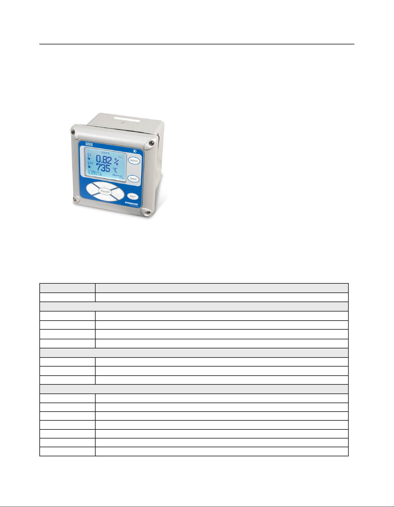
RosemountTM 6888 Xi Digital Transmitter for general purpose
locations
The Rosemount 6888 Xi brings an at a glance view of pertinent
information provided by an easy to use display and interface
which effortlessly connects with a PLC or DCS via HART®/4-20 mA.
It creates a centralized infrastructure for remote autocalibration
devices, diagnostic tools, alarm relay(s), and advanced application
features. The Roesmount 6888Xi is congurable to have up to
two channels for digital inputs or one channel for supporting
traditional architectures.
Easy to use operator interface and design
Plugged diffuser diagnostic measures response time and
detects a plugged diffuser or empty gas bottle
Stochiometer provides an oxygen reading during reducing
conditions, indicating extent of O2 deciency
Additional information
Specications can be found on page 13. Drawings are provided
on page 19.
Specication and selection of product materials, options, or components must be made by the purchaser or the equipment. See
page 13 for more information on material selection.
Table 3. Rosemount 6888 Xi Digital Transmitter for General Purpose Locations
Model Product description
6888Xi Digital Transmitter
Measurement
1OXY Single digital input (HART)
2OXY Single digital input (HART) and ame safety interlock for heater
3OXY Two digital inputs (HART)
1
4OXY
Mounting
00 No hardware
01 Panel mount kit with gasket
02 2 in. pipe/wall mount kit
2
Cable
00 No cable
10 20 ft (6 m) cable, use with traditional architecture probe only
11 40 ft (12 m) cable, use with traditional architecture probe only
12 60 ft (18 m) cable, use with traditional architecture probe only
13 80 ft (24 m ) cable, use with traditional architecture probe only
14 100 ft (30 m) cable, use with traditional architecture probe only
15 150 ft (45 m) cable, use with traditional architecture probe only
1
Single traditional architecture input
8 9
www.Emerson.com/RosemountGasAnalysis
Page 9

December 2017 December 2017Rosemount 6888 Oxygen Transmitter Rosemount 6888 Oxygen Transmitter
Enable: Stochiometer indicator for reducing conditions
00 No
01 Single channel
02 Dual channel
Enable: Programmable reference function
00 No
01 Single channel
02 Dual channel
Enable: Extended temperature function
00 No
01 Single channel
02 Dual channel
Enable: Plugged diffuser diagnostics
00 No
01 Single channel
02 Dual channel
1. Compatible with oxygen probes utilizing a 120 V heater only.
2. Cables are not rated for use in hazardous locations and must be installed in accordance with local and national codes.
www.Emerson.com/RosemountGasAnalysis
Page 10
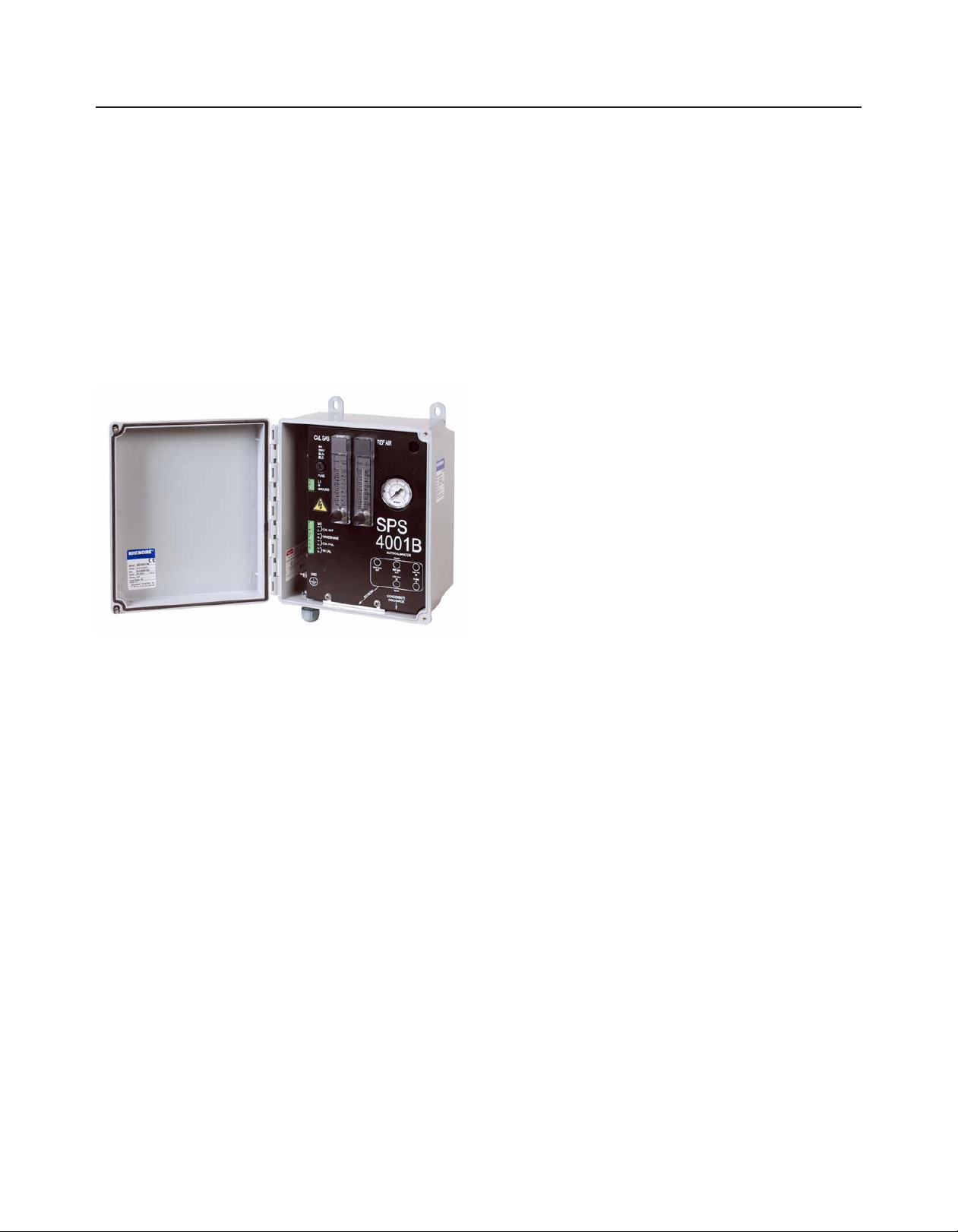
RosemountTM SPS 4001B and Rosemount IMPS 4000
Autocalibration Devices for general purpose locations
The Rosemount SPS 4001B and Rosemount IMPS 4000
are cost-effective calibration systems which conveniently
sequence calibration gases without any labor from an operator
or maintenance technician. Calibration owmeter(s) and
reference air owmeter(s)/regulator(s) are included with the
autocalibration manifold. The calibration can be initiated
by a contact relay or timer or automatically via calibration
recommended diagnostic. The Rosemount SPS 4001B is
designed to automatically calibrate one oxygen analysis system.
The Rosemount IMPS 4000 is congurable to automatically
calibrate one to four oxygen analysis systems. Both the
Rosemount SPS 4001B and Rosemount IMPS 4000 require a
Rosemount 6888 Xi Transmitter or Oxymitter electronics.
Complete autocalibration assembly: includes calibration
owmeter and reference air owmeter/regulator and
solenoids mounted on a single manifold
Automatic calibrations reduce operator time to ensure
continuously accurate readings
Rosemount IMPS 4000 enclosure designed to accept
a customer's z-purge system to meet hazardous area
requirements
Additional information
Specications can be found on page 13. Drawings can be
found on page 19.
Specication and selection of product materials, options, or components must be made by the purchaser of the equipment. See
page 13 for more information on material selection.
10 11
www.Emerson.com/RosemountGasAnalysis
Page 11

December 2017 December 2017Rosemount 6888 Oxygen Transmitter Rosemount 6888 Oxygen Transmitter
Table 4. Rosemount SPS 4001B and Rosemount IMPS 4000 Autocalibration Devices for General Purpose
Locations
Model Product description
XSO2CAL Autocalibration accessories
Single probe autocalibration options
00 None
01 SPS 4001B single probe sequencer
Multiprobe autocalibration options
00 None
01 Intelligent multiprobe sequencer (IMPS) - 1 probe
02 Intelligent multiprobe sequencer (IMPS) - 2 probes
03 Intelligent multiprobe sequencer (IMPS) - 3 probes
04 Intelligent multiprobe sequencer (IMPS) - 4 probes
05 Intelligent multiprobe sequencer (IMPS) with 115 V heater - 1 probe
06 Intelligent multiprobe sequencer (IMPS) with 115 V heater - 2 probes
07 Intelligent multiprobe sequencer (IMPS) with 115 V heater - 3 probes
08 Intelligent multiprobe sequencer (IMPS) with 115 V heater- 4 probes
09 Intelligent multiprobe sequencer (IMPS) with 220 V heater - 1 probe
10 Intelligent multiprobe sequencer (IMPS) with 220 V heater - 2 probes
11 Intelligent multiprobe sequencer (IMPS) with 220 V heater - 3 probes
12 Intelligent multiprobe sequencer (IMPS) with 220 V heater - 4 probes
www.Emerson.com/RosemountGasAnalysis
Page 12
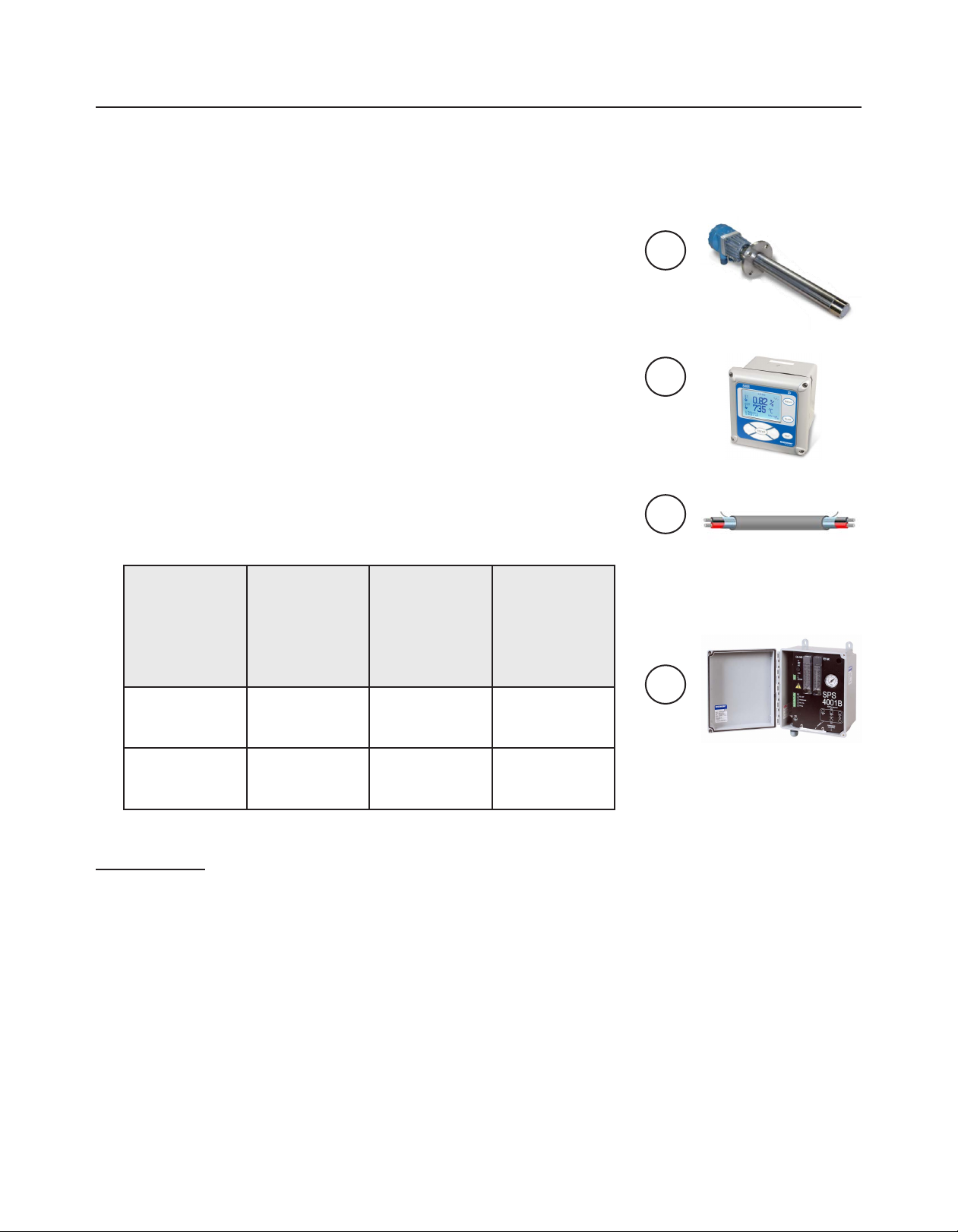
How to order: Complete Oxygen Analysis system
The RosemountTM In-Situ Oxygen Analysis system can be congured as two types of
architectures.
Digital: A digital output of either 4-20 mA with digital signal based on HART® or
FoundationTM Fieldbus is transmitted directly from the probe.
Traditional: Raw sensor and thermocouple voltages are output from the probe to a
remote transmitter. The remote transmitter outputs the 4-20 mA with digital signal
based on HART.
How to order:
1. Choose a Rosemount 6888A or Rosemount 6888C model and decide which type
of architecture is desired. The architecture type is specied in the Housing and
electronics code in the model number.
2. Choose a corresponding Rosemount 6888Xi model1 to match the architecture type
of the Rosemount 6888A or Rosemount 6888C. The architecture type is specied by
the Remote Type code in the model number.
3. Based on the architecture type, choose the appropriate interconnect cable.
4. Rosemount SPS 4001B and Rosemount IMPS 4000 autocalibration devices are
optional to include with an oxygen analysis system.
Architecture Rosemount
6888A/
Rosemount
6888C Housing
and electronics
code
Digital 1HT, 2HT, 4FF 1OXY, 2OXY, 3OXY 18 AWG two wire
Traditional 5DR 4OXY 7 conductor cable,
Rosemount 6888
Xi Remote type
code
Interconnect
cable
shielded cable,
customer supplied
available through
Rosemount
2
1
2
3
4
1. For digital architecture, Rosemount 6888 Xi, Rosemount Field Communicator, or PLC/DCS required to interface
with Rosemount 6888A or 6888C models.
2. 7 conductor cable orderable through Rosemount 6888Xi model matrix or by part number.
12 13
www.Emerson.com/RosemountGasAnalysis
Page 13
December 2017 December 2017Rosemount 6888 Oxygen Transmitter Rosemount 6888 Oxygen Transmitter
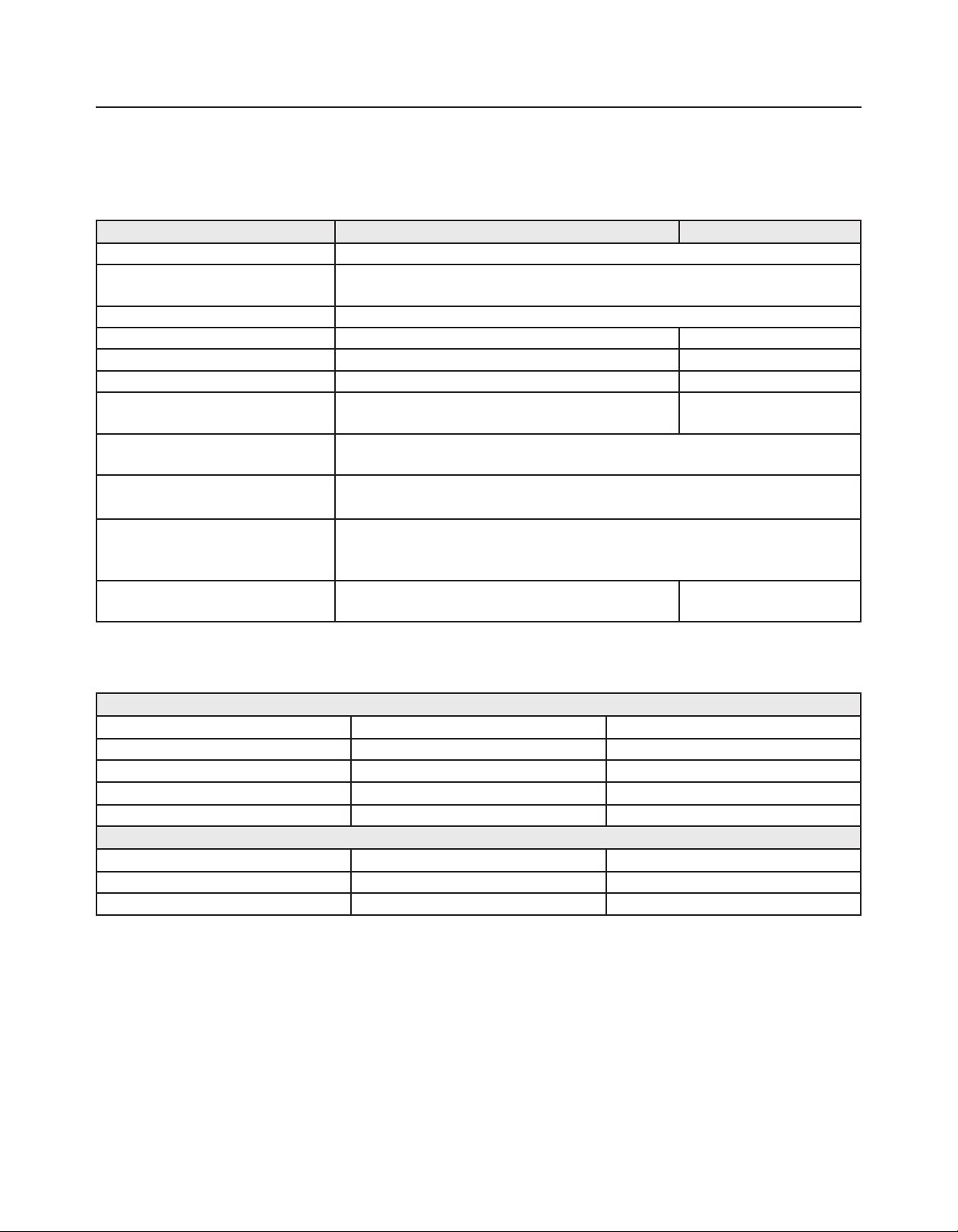
Specifications
Table 5. Performance Specifications
Specification Rosemount
Factory calibrated O2 range 0-10%
User congurable O2 range Lower (LRL) O2: 0 - 10%
Upper (URL) O2: 0 - 50%
Repeatability ±0.75% of reading or 0.05% of O2, whichever is greater
Process temperature effect on repeatability 0.05% O2 for 100 to 700 °C (212 to 1292 °F) temperature range N/A
Lowest detection limit 0.02% O
Calibration gas repeatability ±0.02% O
System speed of response to calibration
1
gas
Accuracy of stochiometer reducing
condition indicator
Reducing conditions: system response From oxidizing to reducing - T90 in 120 sec
Calibration gases Low: 0.4 to 2% O2, balance nitrogen
Reference air (recommended) Instrument air (clean, dry)
T
< 3 seconds
initial
T90 < 8 seconds
±0.1% of reading or 0.1% O2, whichever is greater
From reducing to oxidizing - T90 in 30 sec
High: 8 to 21% O2, balance nitrogen
Regulate to 20 psi (137.9 kPa), 5 schf (2.36 L/min)
Regulate to 5 psi (34 kPa), 2 scfh (0.94 L/min)
TM
6888A, Rosemount 6888C Rosemount 6888 Xi
2
2
N/A
N/A
N/A
N/A
1. Response to process gas changes may vary depending on process conditions and product lifetime.
Table 6. Calibration Modes
Standard housing: Rosemount 6888A, Rosemount 6888C
Additional devices Initiation Gas sequencing
None DCS or eld communicator Manually
Rosemount 6888Xi Manually Manually
Rosemount 6888Xi, Rosemount SP4001B Manually, timer, or contact relay Automated
Rosemount 6888Xi, Rosemount IMPS4000 Manually, timer, or contact relay Automated
Integral autocalibration housing: Rosemount 6888A, Rosemount 6888C
Additional devices Initiation Gas sequencing
None Manually or timer Automated
Rosemount 6888Xi Manually, timer, or contact relay Automated
www.Emerson.com/RosemountGasAnalysis
Page 14
Functional specifications
Temperature limits
Table 7. Process Temperature Limits
Process Process mounting
With snubber diffuser 0 to 400 °C (32 to 750 °F) 200 °C (392 °F) maximum
With ceramic diffuser 0 to 705 °C (32 to 1301 °F) 200 °C (392 °F) maximum
With Hastelloy diffuser 0 to 705 °C (32 to 1301 °F) 200 °C (392 °F)maximum
Bypass accessory 0 to 1050 °C (32 to 1922 °F) 200 °C (392 °F) maximum
Abrasive shield accessory 0 to 705 °C (32 to 1301 °F) 200 °C (392 °F) maximum
1. 190 °C (374 °F) for hazardous locations (only applies to the Rosemount 6888C)
Table 8. Ambient Temperature Limits
Rosemount 6888A Rosemount 6888C Rosemount
6888 Xi
-40 to 70 °C
(-40 to 158 °F)
-40 to 70 °C
(-40 to 158 °F)
-20 to 50 °C
(4 to 122 °F)
Storage temperature limits
-40 to 70 °C (-40 to 158 °F )
Electrical
Rosemount
SPS 4001B
-40 to 65 °C
(-40 to 149 °F)
Rosemount
IMPS 4000
0 to 55 °C
(32 to 131 °F)
1
1
1
Rosemount IMPS
4000 with heater
-35 to 55 °C
(-31 to 131 °F )
Rosemount 6888A/Rosemount 6888C power requirements and consumption
Digital: 120/240 Vac, 50/60 Hz, 260/1020 VA max
Traditional: 120/240 Vac, 50/60 Hz, 260/1020 VA max
Rosemount 6888Xi power requirements
Digital, single/dual inputs: 120/240 Vac, 50/60 Hz, 12 VA max
Digital, single input with ame safety interlock: 120/240 Vac, 50/60 Hz, 260/1020 VA max
1
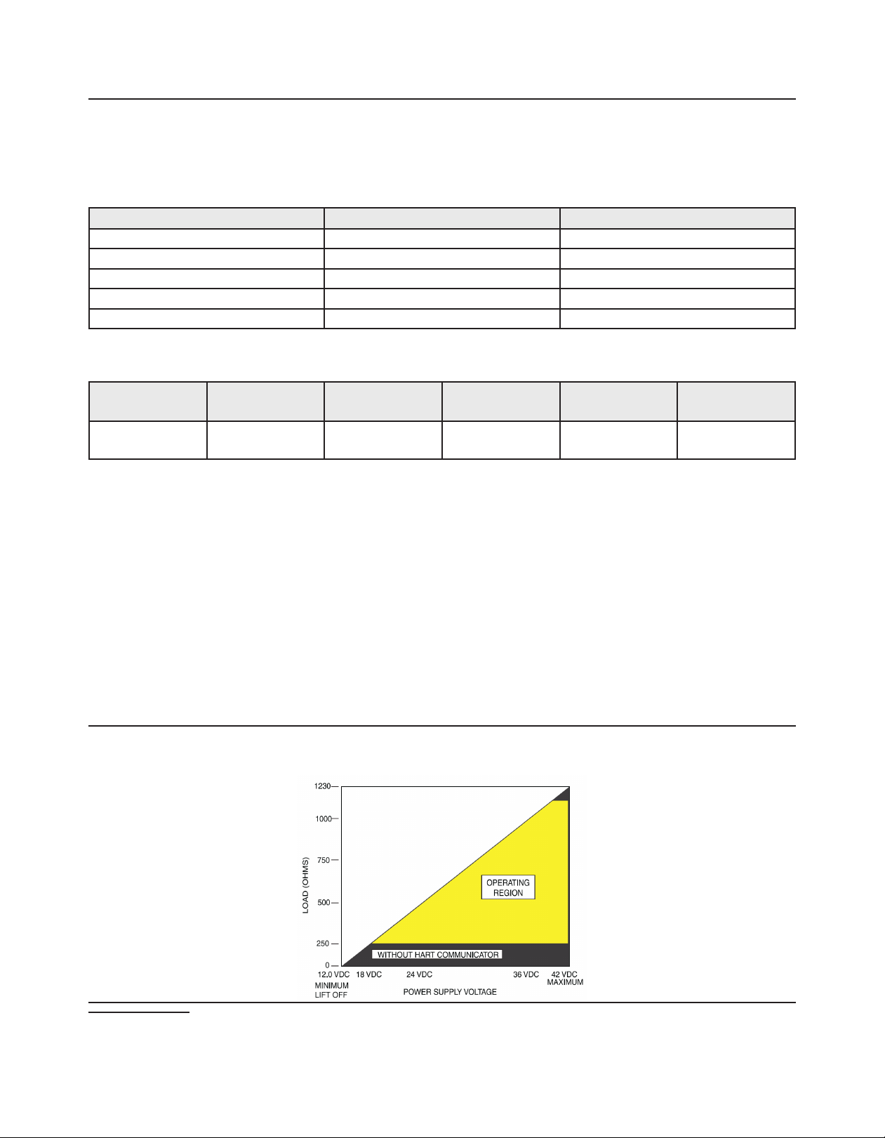
Figure 1. Rosemount 6888A/Rosemount 6888C Transmitter Electronics and Rosemount 6888 Xi Maximum Loop
Resistance is Determined by the Voltage Level of the External Power Supply, as Described by:
1. Power consumption is primarily driven by the oxygen probe.
14 15
www.Emerson.com/RosemountGasAnalysis
Page 15

December 2017 December 2017Rosemount 6888 Oxygen Transmitter Rosemount 6888 Oxygen Transmitter
Load limitations
The Field Communicator requires a minimum loop resistance of 250 Ω for communication.
Rosemount SPS 4001B
100 to 240 Vac, 50/60 Hz, 15 VA
Rosemount IMPS 4000
85 to 264 Vac, 50/60 Hz, 50 VA
Physical specifications
Process wetted parts: 316L or 304 stainless steel
Process connections: 2 in. 150# (4.75 in. (121 mm) bolt circle) DIN (5.71 in. (145 mm) bolt circle)
Orientation: Vertical or horizontal mount
Table 9. Mounting Hardware and Adapter Plates
O.D. Bolt circle Studs
Square weld plate, ANSI studs 7.75 x 7.75 in. (196.85 x 196.85 mm) 6.00 in. (152.4 mm) 5/8-11 UNC
Square weld plate, DIN studs 8.46 x 8.46 in. (215 x 215 mm) 6.69 in. (170 mm) M16 x 2
Adapter to existing ANSI 4 in., 150# ange 9.00 in. (228.6 mm) 7.50 in. (190.5 mm) 5/8-11 UNC
Adapter to existing ANSI 6 in., 150# ange 11.00 in. (297.4 mm) 8.50 in. (215.9 mm) 3/4 - 10 UNC
Adapter to existing ANSI 3 in., 300# ange 8.25 in. (209.55 mm) 6.62 in. (166.15 mm) 3/4 - 10 UNC
Adapter to existing ANSI 4 in., 300# ange 10.00 in. (254 mm) 7.88 in. (200.15 mm) 3/4 - 10 UNC
Spool piece P/N is available to offset probe electronics housing from hot duct work.
ANSI DIN
A 6.00 (153) 7.50 (1.91)
B thread 0.625 (11) M-16 x 2
C diameter 4.75 (121) 5.71 (145)
Table 10. Electrical Conduit Size
Rosemount 6888A Rosemount 6888C Rosemount
6888 Xi
Conduit tting 1/2 - 14 NPT 1/2 - 14 NPT 1/2 - 14 NPT 1/2 - 14 NPT 1/2 - 14 NPT
Number of ttings 2 2 6 2 2
Rosemount
SPS 4001B
Rosemount
IMPS 4000
Table 11. Shipping Weights
6888A 6888C
18 in. (457 mm) standard probe tube 16 lb (7.3 kg) 21 lb (9.5 kg)
3 ft (0.91 m) standard probe tube 21 lb (9.5 kg) 26 lb (11.8 kg)
6 ft (1.83 m) standard probe tube 27 lb (12.2 kg) 32 lb (14.5 kg)
9 ft (2.74 m) standard probe tube 33 lb (15.0 kg) N/A
12 ft (3.66 m) standard probe tube 39 lb (17.7 kg) N/A
www.Emerson.com/RosemountGasAnalysis
Page 16

RosemountTM 6888 product certifications
European Directive information
A copy of the EC Declaration of Conformity can be found at the end of the Rosemount 6888C Quick Start Guide. The most recent
version of the EC Declaration of Conformity can be found at Emerson.com/Rosemount.
Ordinary location certification
As standard, the transmitter has been examined and tested to determine that the design meets the basic electrical, mechanical, and
re protection requirements by a nationally recognized test laboratory (NRTL) as accredited by the Federal Occupational Safety and
Health Administration (OSHA).
Installing equipment in North America
The US National Electrical Code (NEC) and the Canadian Electrical Code (CEC) permit the use of Division marked equipment in Zones
and Zone marked equipment in Divisions. The markings must be suitable for the area classication, gas, and temperature class.
This information is clearly dened in the respective codes.
Rosemount 6888A In-Situ Oxygen Transmitter for general purpose locations
USA
FM Certificate: 3042889
Standards: FM 3810: 2005, ANSI/IEC 250: 2003, ANSI/IEC
60529: 2004
Markings: Type 4X, IP66
Special conditions for use
1. Type 4X and IP66 applies to the transmitter portion that is
mounted externally to the ue duct.
Canada
CSA Certificate: 1913435
Standards: CAN/CSA C22.2 No. 61010-1-04, UL 61010-1:2004
(2nd Edition), UL 50 (11th Ed.), IEC 60529 (Edition
2.1-2001-02), NEMA 250-2003
Markings: Type 4X, IP66
Europe
TUVRheinland
QAL1 Certificate: 0000038506
Standards: EN15267-1:2009, EN15627-2:2009, EN15627-
3:2007, EN14181:2004
MCERTS
Certificates: Sira MC140270/00
Standards: EN15267-1:2009, EN15627-2:2009, EN15627-
3:2007, EN14181:2004
16 17
www.Emerson.com/RosemountGasAnalysis
Page 17

December 2017 December 2017Rosemount 6888 Oxygen Transmitter Rosemount 6888 Oxygen Transmitter
Rosemount 6888C In-Situ Oxygen Transmitter for hazardous locations
USA/Canada
Model String Option Code: C
CSA Certificate: 70100758
Standards: CAN/CSA Standard C22.2 No.0-10:2015, CAN/
CSA C22.2 No.61010-1-12 Harmonized UL 610101:2012 (3rd Edition), CAN/CSA Standard C22.2 No.
94.1-15 Harmonized ANSI/UL Standard 50 (2nd
Edition), CAN/CSA Standard C22.2 No. 94.2-15
Harmonized ANSI/UL Standard 50 (2nd Edition),
CAN/CSA C22.2 No. 60529:16 and ANSI/ISA
60529:04, CAN/CSA Standard C22.2 No. 30-M1986:
2016, CAN/CSA-C22.2 No. 60079-0: 2015, CAN/
CSA-C22.2 No. 60079-1:2016, FM 3600:2011, FM
3615:2006, ANSI/UL-60079-0:2013 (6th Edition),
ANSI/UL-60079-1:2015 (7th Edition))
Markings: Type 4X, IP66, Class 1, Division 1, Groups B, C
and D; T3, Class 1, Zone 1, AEx db IIB+H2 T3 Gb, Ex
db IIB+H2 T3 Gb: -40°C ≤ Ta ≤ +70°C (Autocal Housing
and Probe assembly); -40°C ≤ Ta ≤ +90°C (Standard
Housing and Probe assembly eq. “DR Probe”)
Conditions of acceptability
1. The unit is to be connected to supply mains by qualied
personnel in accordance with national (e.g., CEC, NEC, etc.)
and local codes.
2. Suitable APPROVED switch and fuse or a circuit breaker
shall be provided to facilitate the disconnection of mains
power..
3. The maximum operating ambient is considered as follows:
90 °C for 6888C DR Probe, 70 °C for 6888C Transmitter.
4. Mounting Flange temperature shall not exceed 190 °C
during combustion process.
5. Calibration air lines and reference air lines shall not contain
pure oxygen or combustible gas other than inert/oxygen
gas mixture of which oxygen represents no more than that
normally present in air.
6. The pressure within the enclosure and gas lines shall not be
higher than 1.1 times the atmospheric pressure during the
normal operations of the equipment
7. The 6888C O2 Analyzers are used with the 6888 Xi
Advanced Electronics, which must be installed in a NonHazardous Location, per wiring diagram 6R00131.
8. Meets Enclosure Type 4X & IP66 ratings when the reference
air vent is routed to a dry area.
9. Units installed with conduit runs must have suitably
certied conduit seals installed at the enclosure
10. Units installed with other than conduit runs and conduit
seals, must be tted with certied or listed cable glands
for use in “Class I, Zone 1, Ex/AEx d IIB+H2” and “Class I,
Division 1, Group B, C and D” or better, suitable for the
ambient temperature range.
11. Flameproof joints are not intended to be repaired.
Europe
Model String Option Code: A
ATEX Certificate: Sira 14ATEX1031X
Standards: EN 60079-0:2012/A11:2013, EN 60079-1:2014
Markings: II 2 G Ex db IIB+H2 T3 Gb; IP66;
-40 °C ≤ Ta ≤ +70 °C (Autocal Housing and Probe assembly);
-40 °C ≤ Ta ≤ +90 °C (Standard Housing and Probe assembly eq.
“DR Probe”)
Special conditions for safe use (X):
1. Mounting Flange temperature shall not exceed 190 °C
during combustion process.
2. The 6888C O2 Analyzers are used with the 6888 Xi
Advanced Electronics (associated equipment not part of
this certication) which must be installed in a Safe Area.
3. Calibration air lines and reference air lines shall not contain
pure oxygen or combustible gas other than inert/oxygen
gas mixture of which oxygen represents no more than that
normally present in air.
4. The pressure within the enclosure and gas lines shall not be
higher than 1.1 times the atmospheric pressure during the
normal operations of the equipment.
5. Fasteners property class must be A2-70 Stainless Steel.
6. Flameproof joints are not intended to be repaired.
Model String Option Code: A
IECEx Certificate: IECEx CSA 14.0044X
Standards: IEC 60079-0:2012/A11:2013, IEC 60079-1:2014
Markings: Ex db IIB+H2 T3 Gb; IP66; -40° C ≤ Ta ≤ +70 °C
(Autocal Housing and Probe assembly); -40 °C ≤ Ta ≤ +90 °C
(Standard Housing and Probe assembly eq. “DR Probe”))
Special conditions for safe use (X):
1. Mounting Flange temperature shall not exceed 190 °C
during combustion process.
2. The 6888C O2 Analyzers are used with the 6888 Xi
Advanced Electronics (associated equipment not part of
this certication) which must be installed in a Safe Area.
3. Calibration air lines and reference air lines shall not contain
pure oxygen or combustible gas other than inert/oxygen
gas mixture of which oxygen represents no more than that
normally present in air.
www.Emerson.com/RosemountGasAnalysis
Page 18

4. The pressure within the enclosure and gas lines shall not be higher than 1.1 times the atmospheric pressure during the normal
operations of the equipment.
5. Fasteners property class must be A2-70 Stainless Steel.
6. Flameproof joints are not intended to be repaired.
Rosemount 6888Xi Digital Transmitter for general purpose locations
USA
FM Certificate: 3042889
Standards: FM 3810:2005, ANSI/IEC:2003, ANSI/EC 60529:2004
Markings: Type 4X
Special Conditions for Use:
1. Mounting option 01 was not certied to provide Type 4X ingress protection through the panel cut-out opening. The panel
mount gasket has not been tested for Type 4X installation.
Canada
CSA Certificate: 1913435
Standards: CAN//CSA C22.2 No. 61010-1-04, UL 61010-1:2004 (2nd Edition), CAN/CSA-C22.2 No.94-M91 (R2001), UL 50 (11th
Ed.)
Markings: Type 4X
Rosemount SPS 4001B and Rosemount IMPS 4000 Autocalibration Devices for
general purpose locations
USA/Canada
CSA Certificate: 1640823
Standards: CAN/CSA C22.2 No. 61010-1-04; ANSI/UL 61010-1:2004, (2nd Edition); CSA C22.2 No. 94.1-07; ANSI/UL 50 (12th
Edition); CSA C22.2 No. 94.2 (1st Edition); ANSI/UL 50 E First Edition; CSA C22.2 No. 60529:05 (R2010); ANSI/IEC 605292004 (R2011)
Markings: Type 4X, IP66
18 19
www.Emerson.com/RosemountGasAnalysis
Page 19
December 2017 December 2017Rosemount 6888 Oxygen Transmitter Rosemount 6888 Oxygen Transmitter
Dimensions
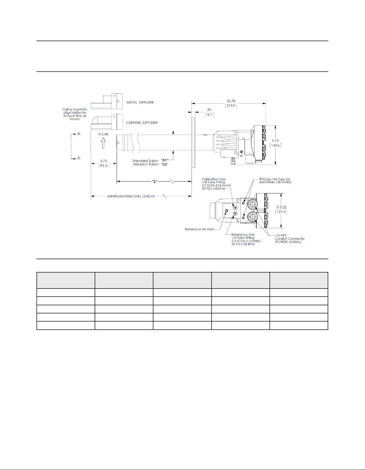
Figure 2. RosemountTM 6888A with Standard Housing
Dimensions are in inches [millimeters].
Table 12. Rosemount 6888A with Standard Housing - Removal/Installation
Probe length Insertion depth (L) Minimum removal
length
18 in. (457 mm) 16.10 in. (409 mm) 27 in. (686 mm) 2.25 in. (57.15 mm) 2.38 in. (60.45 mm)
3 ft (0.91 m) 32.52 in. (826 mm) 46.6 in. (1182 mm) 2.25 in. (57.15 mm) 2.38 in. (60.45 mm)
6 ft (1.83 m) 68.52 in. (1740 mm) 82.6 in. (2097 mm) 2.25 in. (57.15 mm) 2.38 in. (60.45 mm)
9 ft (2.74 m) 104.52 in. (2655 mm) 118.6 in. (3011 mm) N/A 2.38 in. (60.45 mm)
12 ft (3.66 m) 140.52 in. (3569 mm) 154.6 in. (3926 mm) N/A 2.38 in. (60.45 mm)
Standard Tube (D1) Abrasion Tube (D2)
www.Emerson.com/RosemountGasAnalysis
Page 20
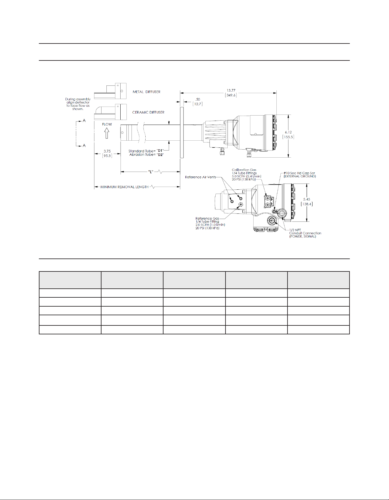
Figure 3. Rosemount 6888A with Autocalibration Housing
Dimensions are in inches [millimeters].
Table 13. Rosemount 6888A with Autocalibration Housing - Removal/Installation
Probe length Insertion depth (L) Minimum removal
length
18 in. (457 mm) 16.10 in. (409 mm) 29.87 in. (759 mm) 2.25 in. (57.15 mm) 2.38 in. (60.45 mm)
3 ft (0.91 m) 32.52 in. (826 mm) 50.1 in. (1271 mm) 2.25 in. (57.15 mm) 2.38 in. (60.45 mm)
6 ft (1.83 m) 68.52 in. (1740 mm) 86.1 in. (2186 mm) 2.25 in. (57.15 mm) 2.38 in. (60.45 mm)
9 ft (2.74 m) 104.52 in. (2655 mm) 122.1 in. (3100 mm) N/A 2.38 in. (60.45 mm)
12 ft (3.66 m) 140.52 in. (3569 mm) 158.1 in. (4015 mm) N/A 2.38 in. (60.45 mm)
Standard Tube (D1) Abrasion Tube (D2)
20 21
www.Emerson.com/RosemountGasAnalysis
Page 21
December 2017 December 2017Rosemount 6888 Oxygen Transmitter Rosemount 6888 Oxygen Transmitter
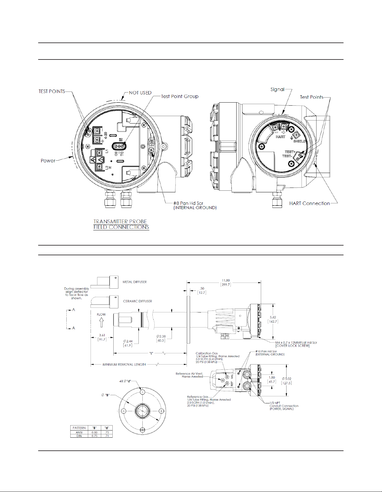
Figure 4. Rosemount 6888A with Autocalibration Housing Field Connections - HART Output
Figure 5. Rosemount 6888C with Standard Housing
Dimensions are in inches [millimeters].
www.Emerson.com/RosemountGasAnalysis
Page 22
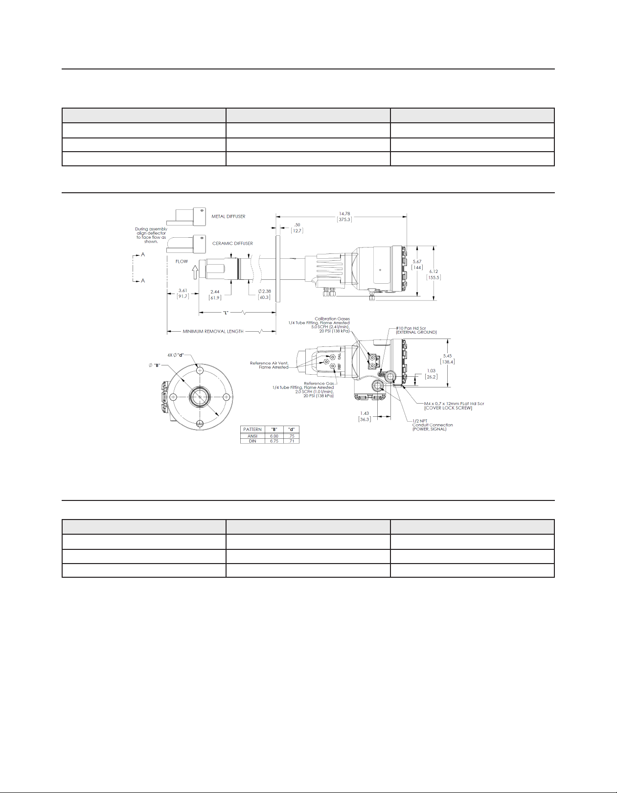
Table 14. Rosemount 6888C with Standard Housing - Removal/Installation
Probe length Insertion Depth (L) Overall product length
18 in. (457 mm) 18.86 in. (479 mm) 27 in. (686 mm)
3 ft (0.91 m) 36.86 in. (936 mm) 46.6 in. (1182 mm)
6 ft (1.83 m) 72.86 in. (1851 mm) 82.6 in. (2097 mm)
Figure 6. Rosemount 6888C with autocalibration housing
Dimensions are in inches [millimeters].
Table 15. Rosemount 6888C with Autocalibration Housing - Removal/Installation
Probe length Insertion depth (L) Minimum removal length
18 in. (457 mm) 16.10 in. (409 mm) 29.87 in. (759 mm)
3 ft (0.91 m) 32.52 in. (826 mm) 50.1 in. (1271 mm)
6 ft (1.83 m) 68.52 in. (1740 mm) 86.1 in. (2186 mm)
22 23
www.Emerson.com/RosemountGasAnalysis
Page 23
December 2017 December 2017Rosemount 6888 Oxygen Transmitter Rosemount 6888 Oxygen Transmitter
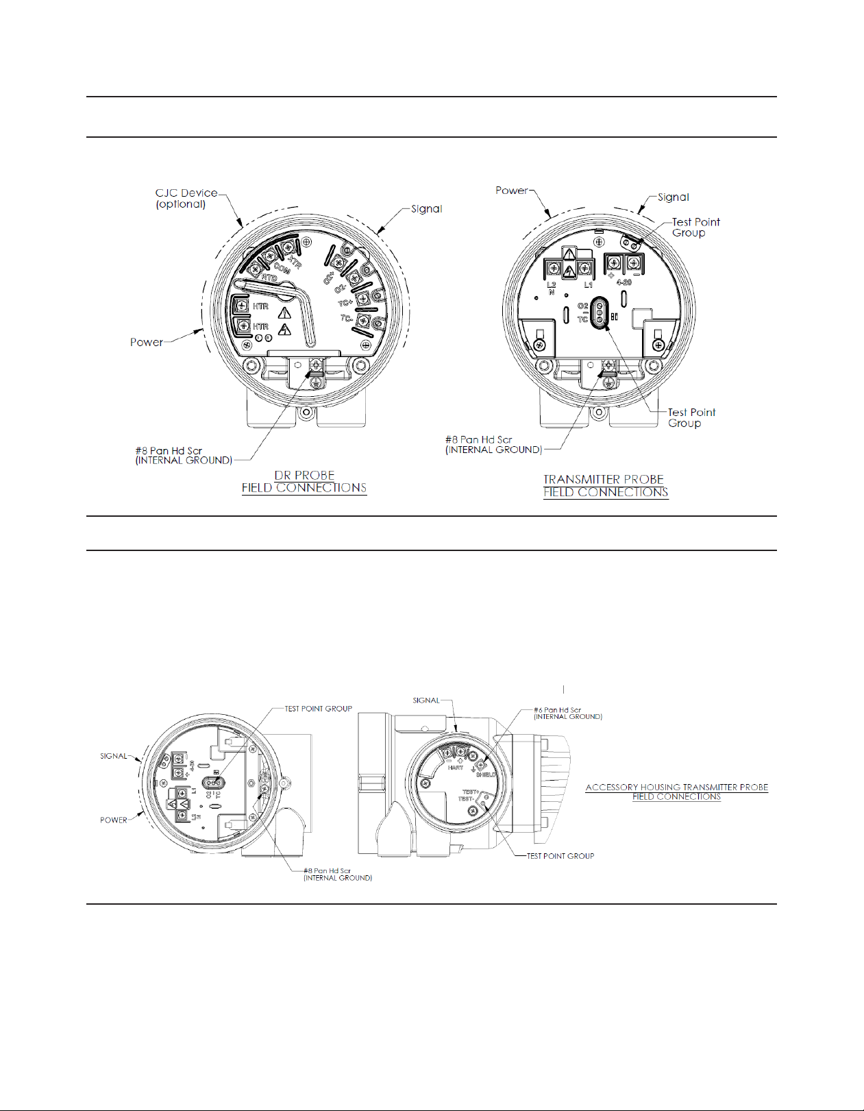
Figure 7. Rosemount 6888C with Standard Housing Field Connections - HART® Output
Figure 8. Rosemount 6888A/6888C with Autocalibration Housing Field Connections - HART Output
www.Emerson.com/RosemountGasAnalysis
Page 24
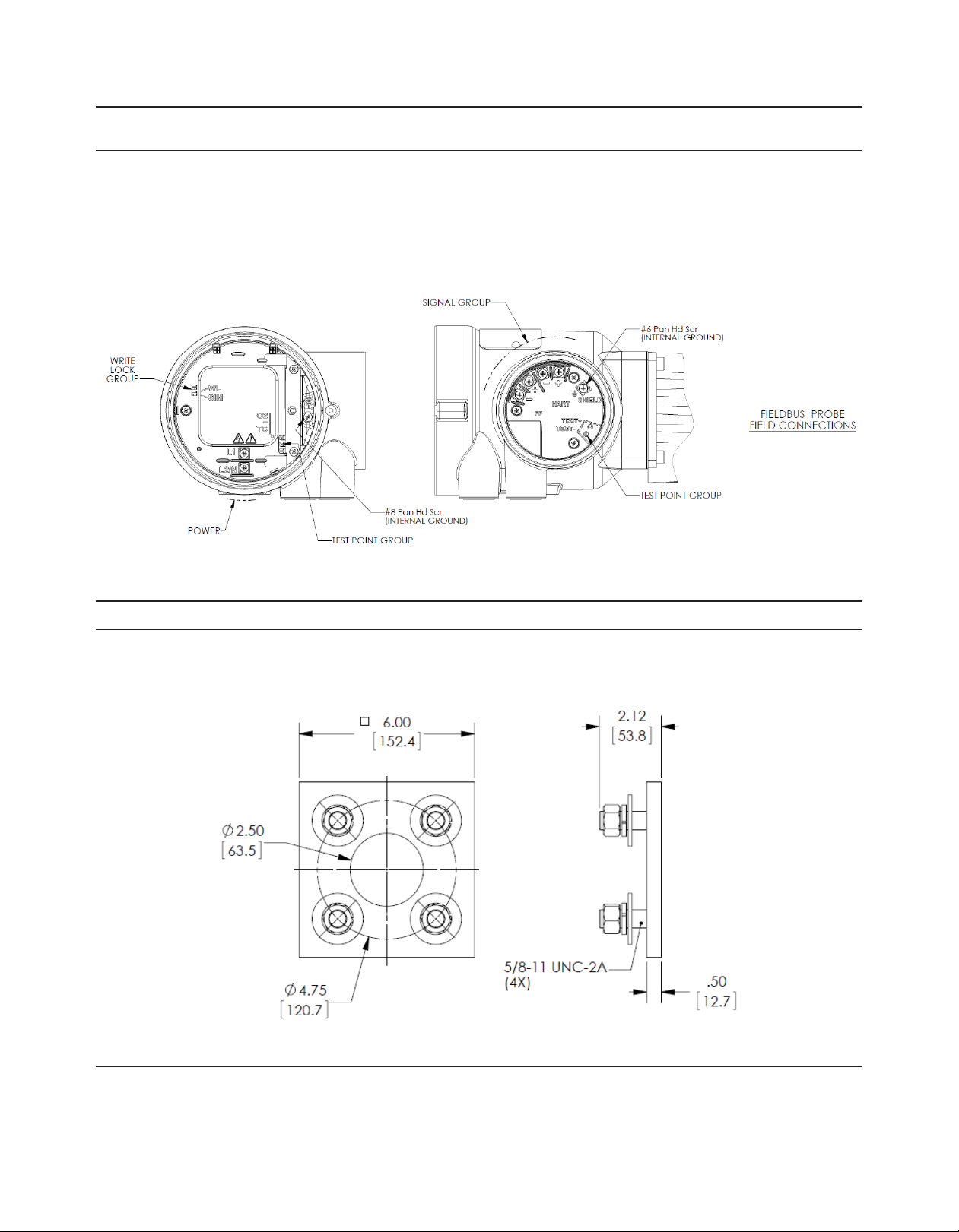
Figure 9. Rosemount 6888A/6888C with Autocalibration Housing Field Connections - FoundationTM Fieldbus
Output
Figure 10. Rosemount 6888A New Installation: Square Weld Plate
Dimensions are in inches [millimeters].
24 25
www.Emerson.com/RosemountGasAnalysis
Page 25
December 2017 December 2017Rosemount 6888 Oxygen Transmitter Rosemount 6888 Oxygen Transmitter
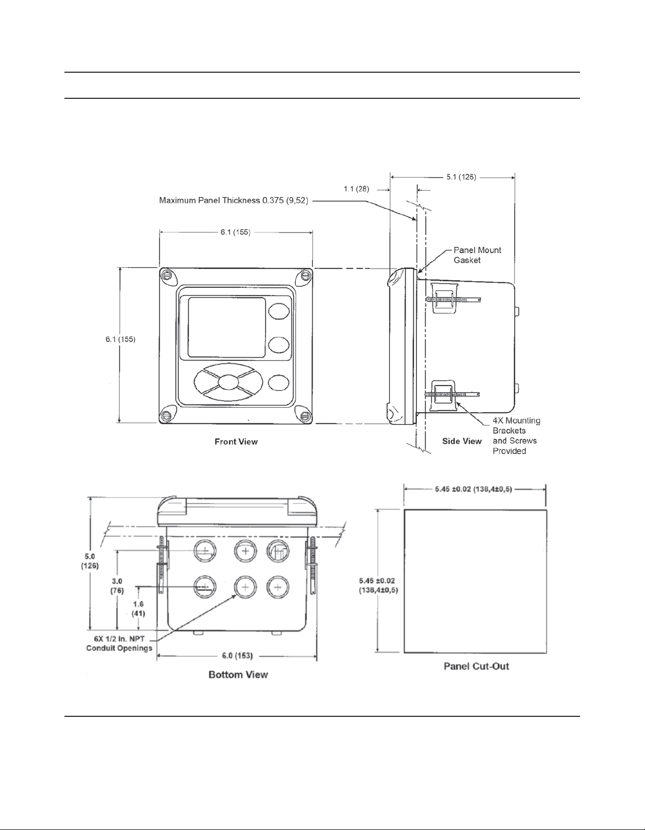
Figure 11. Rosemount 6888Xi with Panel Mount
Dimensions are in inches [millimeters].
www.Emerson.com/RosemountGasAnalysis
Page 26
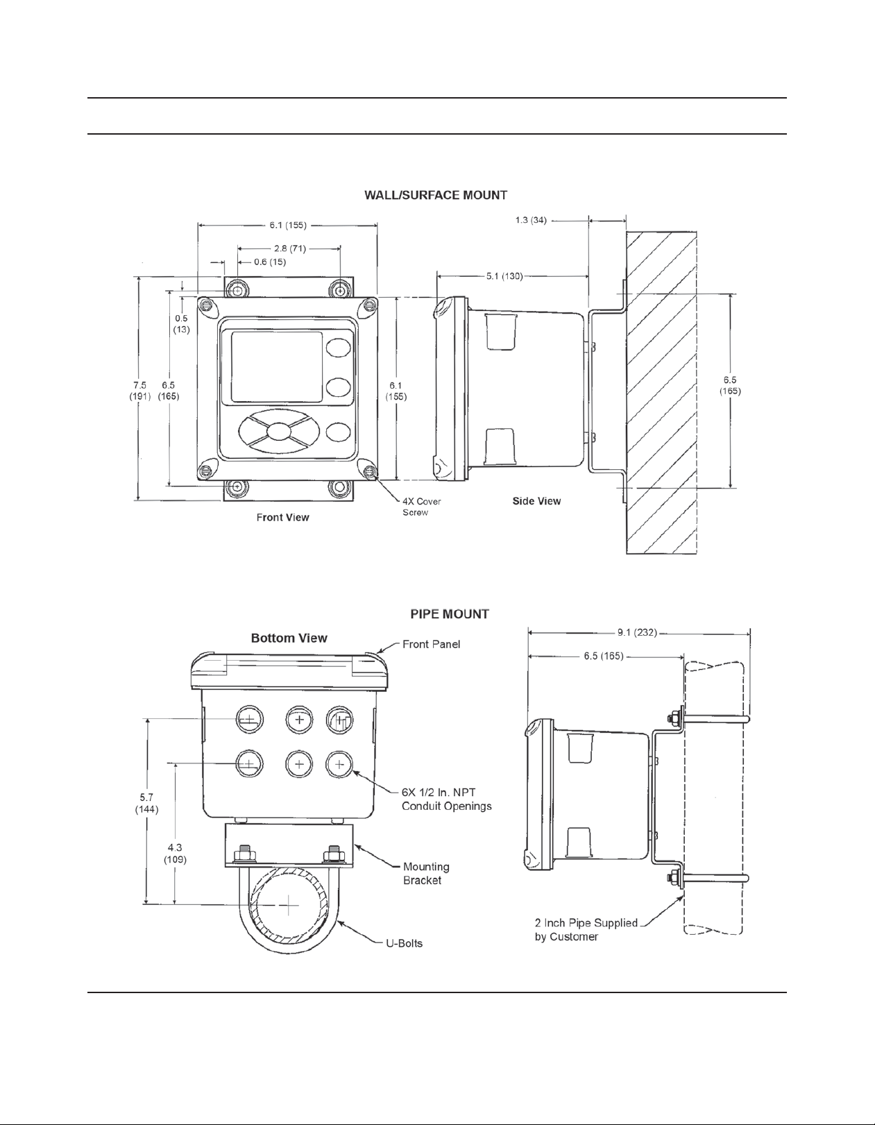
Figure 12. Rosemount 6888 Xi with Wall/Pipe Mount
Dimensions are in inches [millimeters].
26 27
www.Emerson.com/RosemountGasAnalysis
Page 27
December 2017 December 2017Rosemount 6888 Oxygen Transmitter Rosemount 6888 Oxygen Transmitter
Accessories
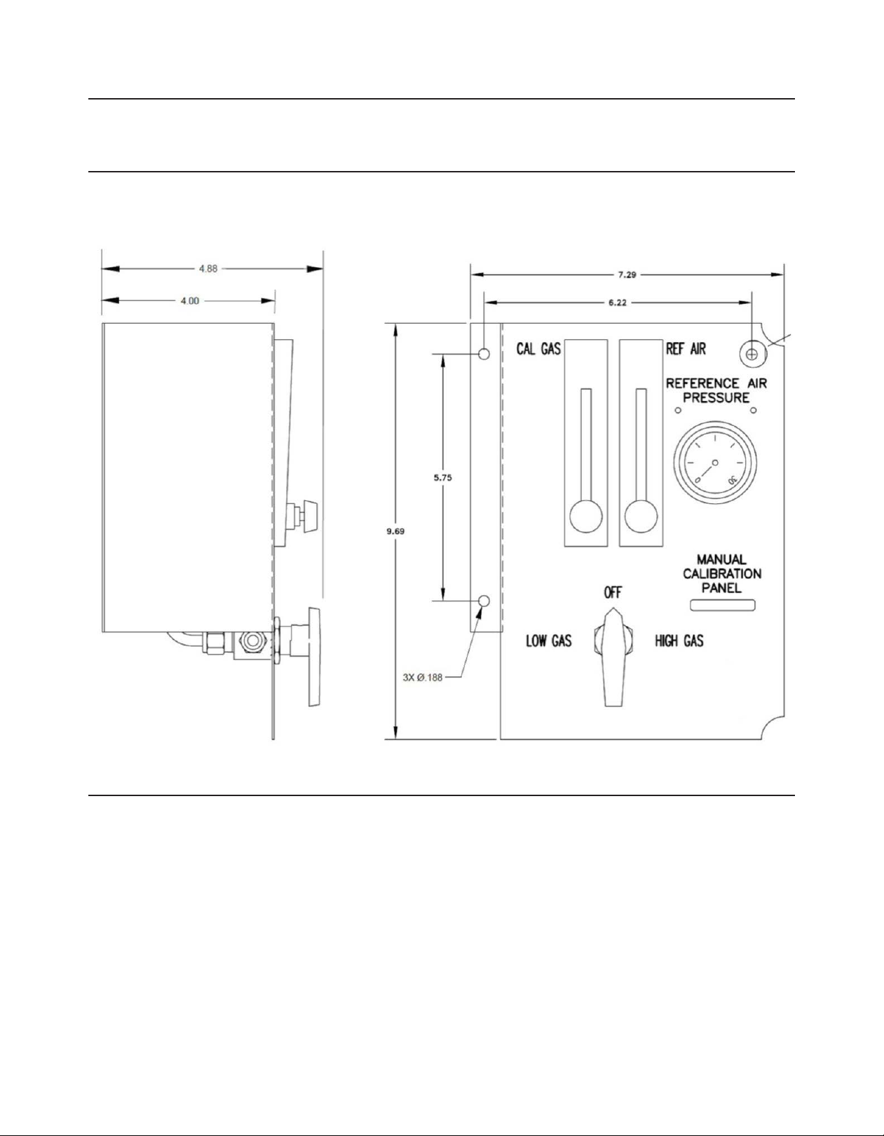
Figure 13. Manual Calibration Panel
Dimensions are in inches.
www.Emerson.com/RosemountGasAnalysis
Page 28
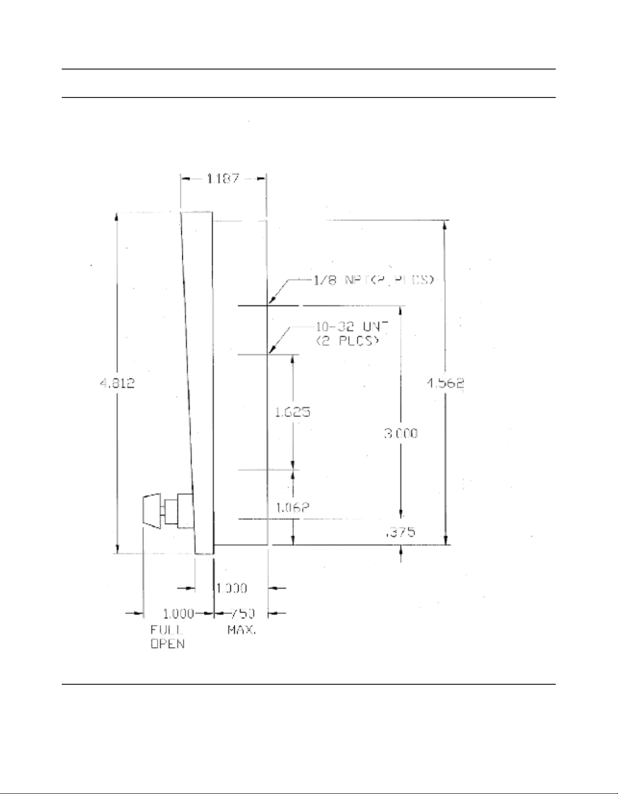
Figure 14. Calibration Gas Flowmeter
Dimensions are in inches.
28 29
www.Emerson.com/RosemountGasAnalysis
Page 29
December 2017 December 2017Rosemount 6888 Oxygen Transmitter Rosemount 6888 Oxygen Transmitter
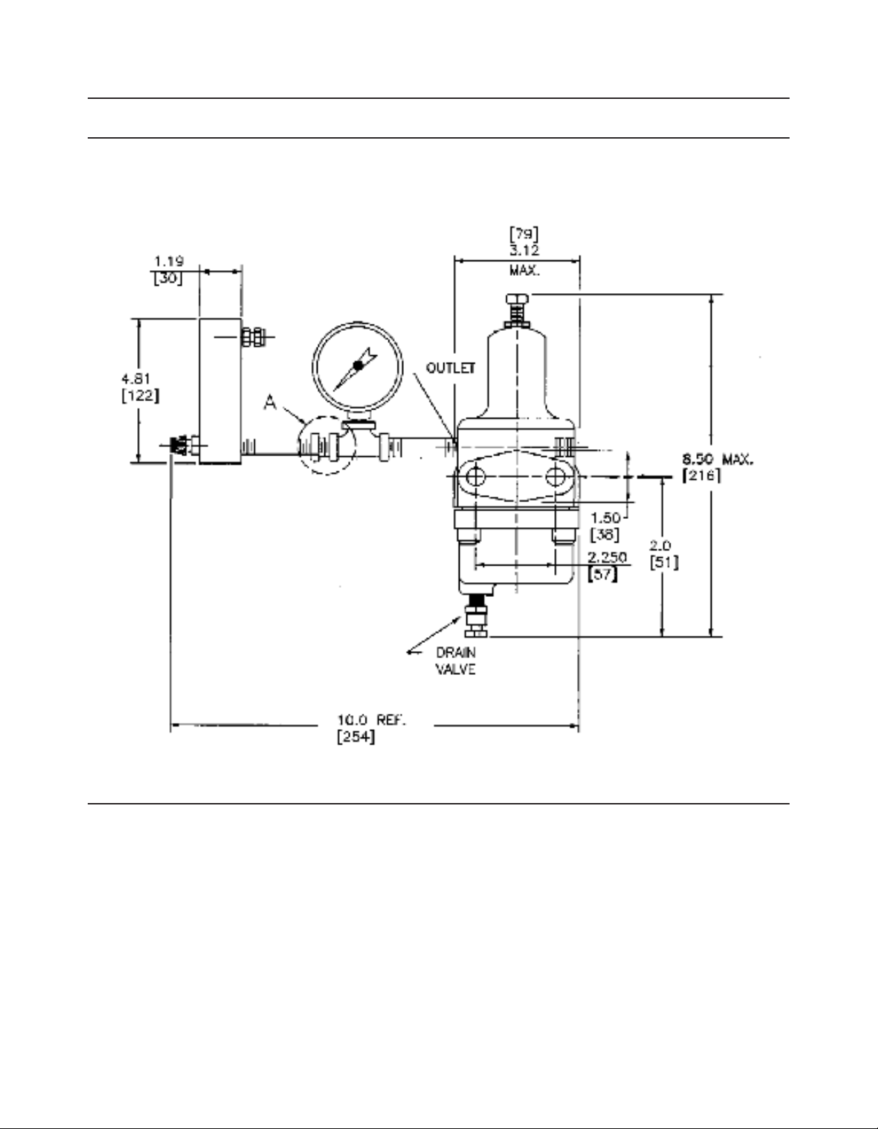
Figure 15. Reference Air Flowmeter and Regulator
Dimensions are in inches [millimeters].
www.Emerson.com/RosemountGasAnalysis
Page 30

Table 15. Rosemount 6888A and Rosemount 6888C Accessories
Rosemount 6888A
part number
6A00444G01
6A00444G02
6A00444G03
6A00444G04
6A00444G05
6A00444G06
6A00444G07
3D39004G01 3 ft (0.9 m) ANSI bypass and mounting hardware package for use with 18 in. (457.2 mm)ANSI
3D39004G02 6 ft (1.8 m) ANSI bypass and mounting hardware package for use with 18 in. (457.2 mm) ANSI
3D39004G03 9 ft (2.7 m) ANSI bypass and mounting hardware package for use with 18 in. (457.2 mm) ANSI
3D39004G07 3 ft (0.9 m) DIN bypass and moutning hardware package for use with 18 in. (457.2 mm) DIN
3D39004G08 6 ft (1.8 m) DIN bypass and mounting hardware package for use with 18 in. (457.2 mm) DIN
3D39004G09 9 ft (2.7 m) DIN bypass and mounting hardware package for use with 18 in. (457.2 mm) DIN
3D39003G01 Abrasive shield assembly: ANSI 3 ft (0.9 m)
3D39003G02 Abrasive shield assembly: ANSI 6 ft (1.8 m)
3D39003G05 Abrasive shield assemby: DIN 3 ft (0.9 m)
3D39003G06 Abrasive shield assembly: DIN 6 ft (1.8 m)
3D39003G07 Abrasive shield assembly: ANSI 9 ft (2.7 m)
3D39003G08 Abrasive shield assembly: ANSI 12 ft (3.7 m)
3D39003G11 Abrasive shield assembly: DIN 9 ft (2.7 m)
3D39003G12 Abrasive shield assembly: DIN 12 ft (3.7 m)
3D39003G13 Abrasive shield assembly: ANSI 18 in. (457.2 mm)
3D39003G15 Abrasive shield assembly: DIN 18 in. (457.2 mm)
3D39003G25 Abrasive shield assembly: ANSI 15 ft (4.6 m)
3D39003G27 Abrasive shield assembly: DIN 15 ft (4.6 m)
3D39003G28 Abrasive shield assembly: ANSI 18 ft (5.5 m)
3D39003G30 Abrasive shield assembly: DIN 18 ft (5.5 m)
4512C36G01 New installation square weld plate: 6 in. (152.4 mm) sq., 4.75 in. (120.7) bolt circle, 5/8-11
4512C36G02 New installation, square weld plate: 7.5 in. (190.5 mm) sq., 5.7 in. (145 mm) bolt circle, M16x2
353B30G04 Adapter plate: OXT4A/OCX/6888A ANSI to 3 in. (76.2 mm) 150# ANSI
353B30G01 Adapter plate: OXT4A/OCX/6888A ANSI to 4 in. (101.6 mm) 150# ANSI
353B30G05 Adapter plate: OXT4A/OCX/6888A ANSI to 6 in. (152.4 mm) 150# ANSI
353B30G10 Adapter plate: OXT4A/OCX/6888A ANSI to 3 in. (76.2 mm) 300# ANSI
4851B78G21 Adapter plate: OXT4A/OCX/6888A ANSI to 4 in. (101.6 mm) 300# ANSI
3D39761G02 Spool piece 12 in. (304.8 mm)
1. Cables are supplied with Exd Rated Glands; the cable is not Exd rated, and installation in a hazardous area is the responsibility of the installer/customer. Cables must
be installed in accordance with national and local electrical codes.
1
1
1
1
1
1
1
30 31
Rosemount 6888C
part number
6A00202G09
6A00202G10
6A00202G11
6A00202G12
6A00202G13
6A00202G14
6A00202G15
1
1
1
1
1
1
1
Description
20 ft (6.1 m) cable, traditional architecture, 1/2 NPT / 1/2 NPT
40 ft (12.2 m) cable, traditional architecture, 1/2 NPT / 1/2 NPT
60 ft (18.3 m) cable, traditional architecture, 1/2 NPT / 1/2 NPT
80 ft (24.4 m) cable, traditional architecture, 1/2 NPT / 1/2 NPT
100 ft (30.5 m) cable, traditional architecture, 1/2 NPT / 1/2 NPT
150 ft (45.7) cable, traditional architecture, 1/2 NPT / 1/2 NPT
200 ft (60.1 m) cable, traditional architecture, 1/2 NPT / 1/2 NPT
general purpose Rosemount 6888A, OXT4A, WC3000 O2 probes
general purpose Rosemount 6888A, OXT4A, WC3000 O2 probes
general purpose 6888A, OXT4A, WC3000 O2 probes
general purpose Rosemount 6888A, OXT4A, WC3000 O2 probes
general purpose Rosemount 6888A, OXT4A, WC3000, O2 probes
general purpose Rosemount 6888A, OXT4A, WC3000, O2 probes
studs
studs
www.Emerson.com/RosemountGasAnalysis
Page 31
December 2017 December 2017Rosemount 6888 Oxygen Transmitter Rosemount 6888 Oxygen Transmitter
Table 16. Calibration Gas and Reference Air Accessories
Part number Description
6A00252G02 Manual calibration panel, includes reference air regulator and owmeter, calibration gas owmeter
263C152G01 Reference air regulator and owmeter set
771B635H01 Calibration gas owmeter
1A9919G01 O2 cal gas kit: contains 0.4% and 8.0% O2 bottles, 550 L each (requires two CGA 590 regulators)
1A9919G02 O2 cal gas regulators kit: contains two CGA 590 regulators
1A9911G03 Wall bracket kit for two O2 gas bottles
Table 17. Rosemount 6888 Xi Accessories
Part number Description
6P00285H01 Xi/6888Xi panel gasket
6A00237H33 Xi/6888Xi panel mount hardware
6A00237H24 Xi/6888Xi pipe and wall mount hardware
www.Emerson.com/RosemountGasAnalysis
Page 32

Rosemount 6888 Oxygen Transmitter
CMB-PDS-6888
Global Headquarters
Emerson Automation Solutions
6021 Innovation Blvd.
Shakopee, MN 55379, USA
+1 800 999 9307 or +1 952 906 8888
+1 952 949 7001
[email protected]
North America Regional Office
Emerson Automation Solutions
8200 Market Blvd.
Chanhassen, MN 55317, USA
+1 800 999 9307 or +1 952 906 8888
+1 952 949 7001
[email protected]
Latin America Regional Office
Emerson Automation Solutions
1300 Concord Terrace, Suite 400
Sunrise, FL 33323, USA
+1 954 846 5030
+1 952846 5121
[email protected]
Product Data Sheet
December 2017
Europe Regional Office
Emerson Automation Solutions Europe GmbH
Neuhofstrasse 19a P.O. Box 1046
CH 6340 Baar
Switzerland
+1 954 846 5030
+1 952846 5121
R[email protected]
Asia Pacific Regional Office
Emerson Automation Solutions
1 Pandan Crescent
Singapore 128461
+65 6777 8211
+65 6777 0947
[email protected]
Middle East and Africa Regional Office
Emerson Automation Solutions
Emerson FZE P.O. Box 17033
Jebel Ali Free Zone - South 2
+971 4 8118100
+971 4 88665465
[email protected]
Analyticexpert.com
Linkedin.com/company/Emerson-Automation-Solutions
Twitter.com/Rosemount_News
Facebook.com/Rosemount
Youtube.com/user/RosemountMeasurement
Google.com/+RosemountMeasurement
The Emerson logo is a trademark and service mark of Emerson Electric
Co.
Rosemount and Rosemount logotype are trademarks of Emerson.
All other marks are the property of their respective owners.
© 2017 Emerson. All rights reserved.
 Loading...