

Page 1
Quick Start Guide
00825-0100-4585, Rev AB
Rosemount™ 585 Annubar™ Flanged
Assembly
June 2016
Page 2
Quick Start Guide
June 2016
NOTICE
This guide provides basic guidelines for Rosemount 585 Annubar Assembly. It does not provide instructions
for configuration, diagnostics, maintenance, service, troubleshooting, Explosion-proof, Flame-Proof, or
intrinsically safe (I.S.) installations. Refer to the Rosemount 585 Reference Manual (document number
00809-0100-4585) for more instruction. This manual is also available electronically on
www.rosemount.com.
If the Rosemount Annubar was ordered assembled to a Rosemount Pressure Transmitter, see the following
Quick Start Guides for information on configuration and hazardous locations certifications:
Rosemount 3051S Series Pressure Transmitter and Rosemount 3051SF Series Flowmeter Quick Start
Guide.
Rosemount 3051S MultiVariable Transmitter and Rosemount 3051SF Series Flowmeter MultiVariable
Tra ns mi tte r Quick Start Guide
Rosemount 3051 Pressure Transmitter and Rosemount 3051CF Series Flowmeter Transmitter Quick
Start Guide.
Rosemount 2051 Pressure Transmitter and Rosemount 2051CF Series Flowmeter Transmitter Quick
Start Guide.
Process leaks may cause harm or result in death. To avoid process leaks, only use gaskets designed to seal with
the corresponding flange and o-rings to seal process connections. Flowing medium may cause the
Rosemount 585 Annubar Assembly to become hot and could result in burns.
If pipe/duct wall is less than 0.125-in. (3,2 mm) use extreme caution when installing sensor. Thin walls can
deform during welding, installation or from the weight of a cantilevered flowmeter. These installations may
require a fabricated outlet, saddle or external flowmeter support. Consult factory for assistance
.
Contents
Location and orientation . . . . . . . . . . . 4
Drill holes into pipe . . . . . . . . . . . . . . . . 7
Assemble and check fit-up . . . . . . . . . . 8
Weld mounting hardware . . . . . . . . . . 9
2
Insert the Rosemount Annubar Sensor . . . . . . . . . . 12
Mount the transmitter . . . . . . . . . . . . . . . . . . . . . . . . 12
Product certifications . . . . . . . . . . . . . . . . . . . . . . . . . 18
Page 3
June 2016
A
B
F
G
C
D
H
A
E
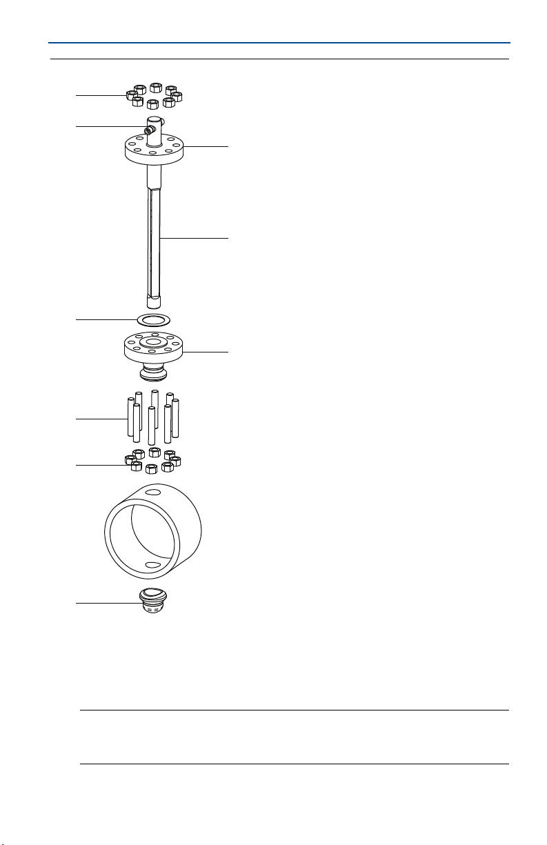
Figure 1. Rosemount 585 Annubar Assembly Exploded View
Quick Start Guide
A. Nuts
B. Remount mount instrument connection
C. Gasket
D. Studs
Note
Use an appropriate pipe sealing compound rated for the service temperature on all
threaded connections.
E. Opposite side support
F. S en sor fla ng e
G. Rosemount 585 Annubar Sensor
H. Mounting flange assembly
3
Page 4
Quick Start Guide
1.0 Location and orientation
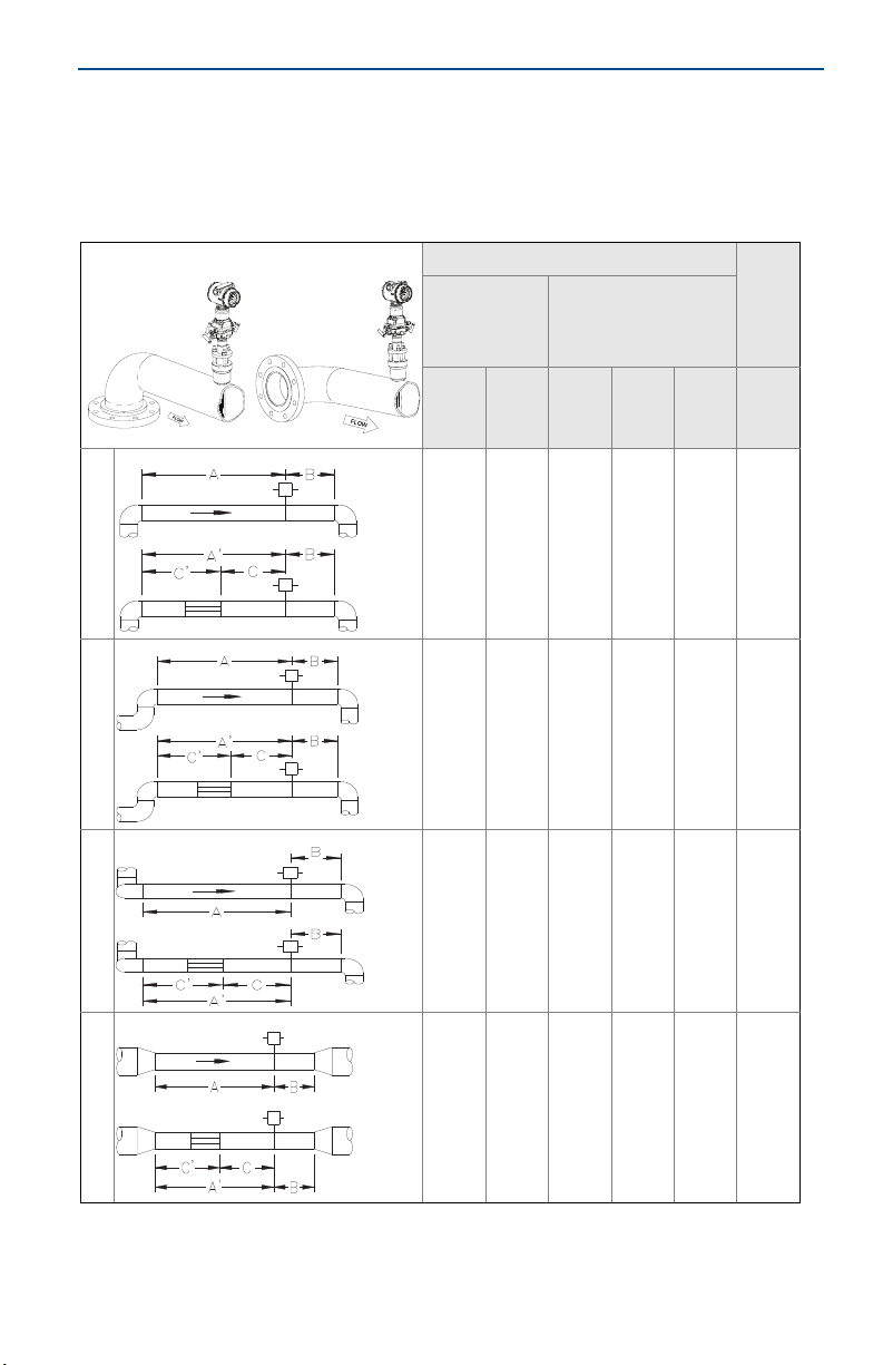
Correct orientation and straight run requirements must be met for accurate and
repeatable flow measurements. Refer to Table 1 for minimum pipe diameter
distances from upstream disturbances.
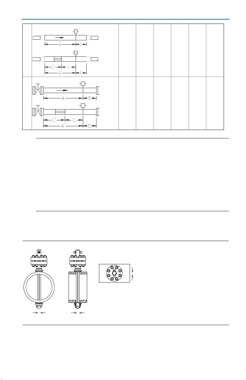
Table 1. Straight Run Requirements
In plane____________Out of plane Upstream pipe diameters
June 2016
Without
straightening
vanes
In
Out of
plane
plane
A
8
1
N/A10N/A
11
2
N/A16N/A
23
3
With straightening
vanes
A’ C C’ B
A
N/A8N/A4N/A
N/A8N/A4N/A
N/A8N/A4N/A
Downstream
pipe diameters
4
4
4
4
4
4
4
N/A28N/A
12
4
N/A12N/A
N/A8N/A4N/A
4
4
4
4
4
4
Page 5
June 2016
Quick Start Guide
18
5
N/A18N/A
30
6
N/A30N/A
N/A8N/A4N/A
4
N/A8N/A4N/A
4
Note
Consult the factory for instructions regarding use in square or rectangular
ducts.
“In plane A” means the sensor is in the same plane as the elbow. “Out of plane
A” means the bar is perpendicular to the plane of the elbow.
If proper lengths of straight run are not available, position the mounting such
that 80% of the run is upstream and 20% is downstream.
Use straightening vanes to reduce the required straight run length.
Row 6 in Ta bl e 1 applies to gate, globe, plug, and other throttling valves that
are partially opened, as well as control valves.
4
4
4
4
1.1 Misalignment
Rosemount 585 Annubar installation allows for a maximum misalignment of 3°.
Figure 2. Misalignment
±3°
±3°±3°
5
Page 6
Quick Start Guide
45°
45°
Recommended
zone 90°
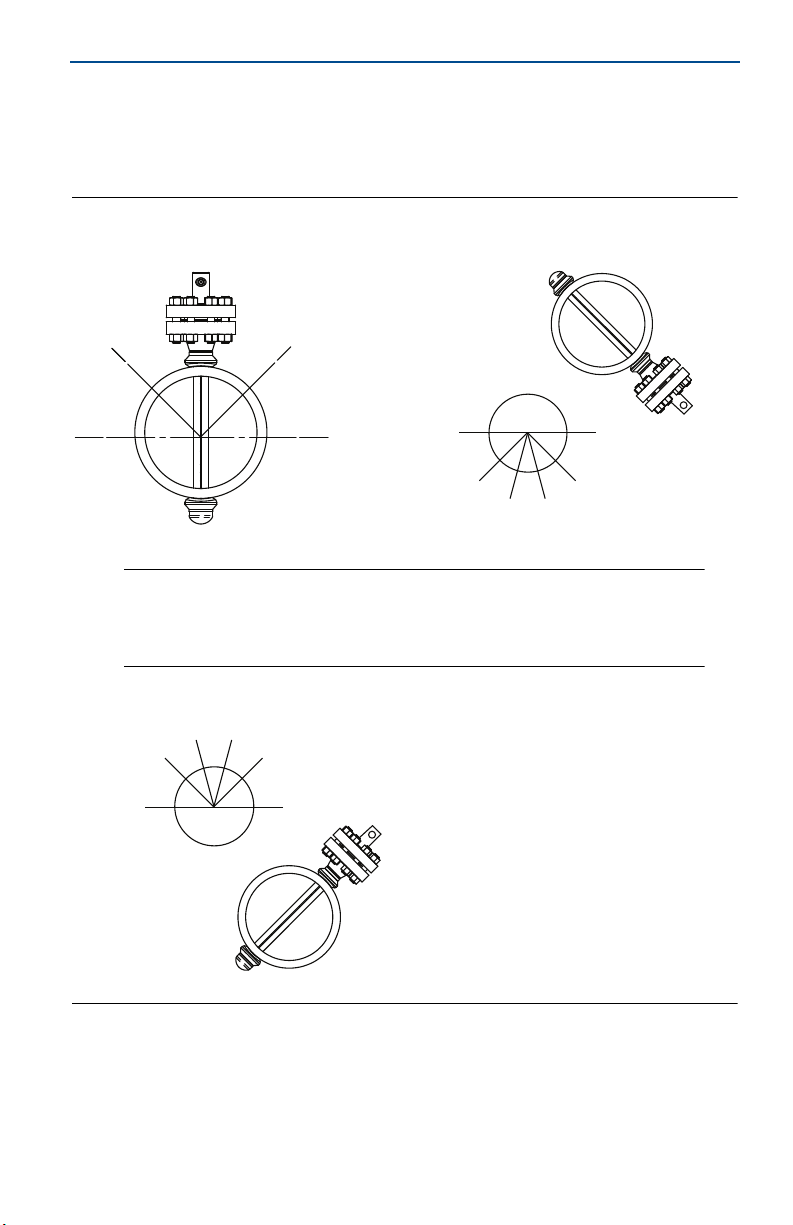
1.2 Horizontal Orientation
For proper venting and draining, the sensor should be located in the upper half of
the pipe for gas applications. For liquid and steam applications, the sensor should
be located in the bottom half of the pipe.
Figure 3. Horizontal Orientation
Gas Liquid and steam
45°45°
June 2016
Recommended
zone 30°
Recommended
30°
zone 30°
Note
Top mounting for steam applications is an appropriate mounting option in many
cases. Consult Rosemount Customer Central for instructions regarding steam on top
mounting.
Steam on top
Recommended
zone 30°
45°
Recommended
30°
zone 30°
45°
6
Page 7
June 2016
Quick Start Guide
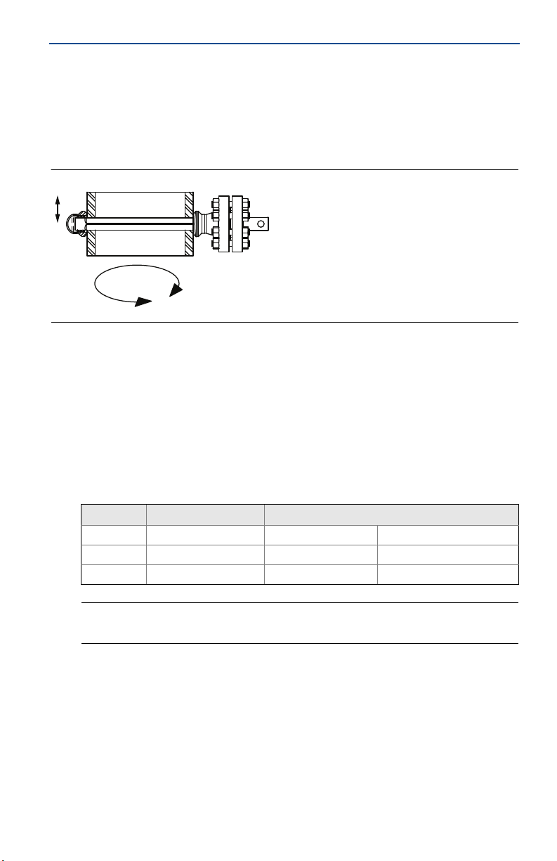
1.3 Vertical Orientation
The sensor can be installed in any position around the circumference of the pipe,
provided the vents are positioned properly for bleeding or venting. Optimal
results for liquid or steam are obtained when flow is up. For steam applications, a
90° spacer is included to provide water legs to ensure the transmitter stays within
temperature limits.
Figure 4. Liquid, Gas, or Steam
Flow
360°
2.0 Drill holes into pipe
1. Determine the sensor size based on the probe width (see Ta bl e 2).
2. Depressurize and drain the pipe.
3. Select the location to drill the hole.
4. Determine the diameter of the hole to be drilled according to the
specifications in Ta bl e 2 . Drill the mounting hole into the pipe with a hole saw
or drill. DO NOT TORCH CUT THE HOLE.
Table 2. Sensor Size/Hole Diameter Chart
Sensor size Sensor width Hole diameter
11 0.80-in. (20,32 mm)
22 1.20-in. (30,48 mm) 15/16-in. (34 mm) +1/16-in. (1,6 mm) – 0.00
44 2.30-in. (58,42 mm) 21/2-in. (64 mm) +1/16-in. (1,6 mm) – 0.00
7
/8-in. (19 mm) +1/32-in (0,8 mm) – 0.00
Note
Drill the hole 180° from the first hole for opposite- side support models.
7
Page 8

Quick Start Guide
Drill the appropriate diameter hole
through the pipe wall.
5. A second identically sized hole must be drilled opposite the first hole so that
the sensor can pass completely through the pipe. To drill the second hole,
follow these steps:
a. Measure the pipe circumference with a pipe tape, soft wire, or string. (For
the most accurate measurement the pipe tape needs to be perpendicular to
the axis of flow.)
b. Divide the measured circumference by two to determine the location of the
second hole.
c. Re-wrap the pipe tape, soft wire, or string from the center of the first hole.
Then, using the number calculated in the preceding step, mark the center of
what will become the second hole.
d. Using the diameter determined in step 3, drill the hole into the pipe with a
hole saw or drill. DO NOT TORCH CUT THE HOLE.
6. Deburr the drilled holes on the inside of the pipe.
3.0 Assemble and check fit-up
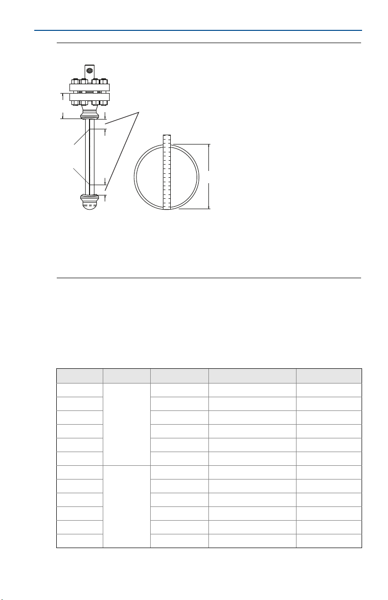
For accurate measurement, use the following steps to ensure that Ports A and B
are equal distances from the inside walls of the pipe.
1. Assemble the Rosemount 585 to the mounting hardware with the gaskets and
bolts.
2. Hand tighten the bolts just enough to hold the position of the sensor centered
in the mounting hardware.
3. Check the fit of the assembly to the pipe by inserting a rule or stiff wire
through both mounting holes. Note the distance. All sensing holes must be
inside the pipe inner diameter. See Figure 5.
4. Add
5. Measure the distance from the high point of the butt weld branch connection
6. Measure the distance from the end of the transferred length in step 4 to the
7. Compare the numbers obtained in steps 5 and 6.
Small discrepancies can be compensated for with the fit-up of the mounting
hardware. Large discrepancies may cause installation problems or error.
1
/16-in. (1,6 mm) to the measured distance for the weld gap and transfer
to the assembly starting at the high point of the butt weld branch connection.
1
to the first sensing hole, port B, then subtract
/16-in (1,6 mm).
last sensing hole, port A.
June 2016
8
Page 9
June 2016
A
C
B
E
D
Quick Start Guide
Figure 5. Fit-up Check for Rosemount 585 with Opposite-Side Support
A. Outer Diameter to Flange (ODF)
B. Port A
C. Port B
D. The same within
E. Pipe outside diameter
1
/8-in. (3 mm)
4.0 Weld mounting hardware
1. Center the flanged assembly over the mounting hole, gap 1/16-in. (1,6 mm),
and measure the distance from the outer diameter of the pipe to the face of
the flange. Compare this to Ta bl e 3 and adjust the gap as necessary.
Table 3. Flange Sizes and ODF per Sensor Size
Sensor size Flange type Pressure class Flange size/rating/type ODF in. (mm)
11
11 3 11/2-in. 300# RF 4.13 (105)
11 6 11/2-in. 600# RF 4.44 (113)
11 N 11/2-in. 900# RF 4.94 (125)
11 F 11/2-in. 1500# RF 4.94 (125)
11 T 11/2-in. 2500# RF 6.76 (172)
11
11 3 11/2-in. 300# RTJ 4.32 (110)
11 6 11/2-in. 600# RTJ 4.44 (113)
11 N 11/2-in. 900# RTJ 4.94 (125)
11 F 11/2-in. 1500# RTJ 4.94 (125)
11 T 11/2-in. 2500# RTJ 6.82 (173)
A
R
1 11/2-in. 150# RF 3.88 (99)
1 11/2-in. 150# RTJ 4.07 (103)
(1)
9
Page 10

Quick Start Guide
June 2016
11
11 3 DN40 PN40 RF 3.21 (81)
11 6 DN40 PN100 RF 3.88 (99)
22
22 3 2.0-in. 300# RF 4.38 (111)
22 6 2.0-in. 600# RF 4.76 (121)
22 N 2.0-in. 900# RF 5.88 (149)
22 F 2.0-in. 1500# RF 5.88 (149)
22 T 3.0-in. 2500# RF 9.87 (251)
22
22 3 2.0-in. 300# RTJ 4.63 (117)
22 6 2.0-in. 600# RTJ 4.82 (122)
22 N 2.0-in. 900# RTJ 5.94 (151)
22 F 2.0-in. 1500# RTJ 5.94 (151)
22 T 3.0-in. 2500# RTJ 10.00 (254)
22
22 3 DN50 PN40 RF 3.52 (89)
22 6 DN50 PN100 RF 4.31 (109)
44
44 3 3.0-in. 300# RF 5.00 (126.9)
44 6 3.0-in. 600# RF 5.38 (136.6)
44 N 4.0-in. 900# RF 8.19 (208.0)
44 F 4.0-in. 1500# RF 8.56 (217.5)
44 T 4.0-in. 2500# RF 11.19 (284.2)
44
44 3 3.0-in. 300# RTJ 5.25 (133)
44 6 3.0-in. 600# RTJ 5.44 (138)
44 N 4.0-in. 900# RTJ 8.25 (209)
44 F 4.0-in. 1500# RTJ 8.63 (219)
44 T 4.0-in. 2500# RTJ 11.38 (289)
44
44 3 DN80 PN40 RF 4.16 (106)
44 6 DN80 PN100 RF 4.95 (126)
D
A
R
D
A
R
D
1 DN40 PN16 RF 3.21 (81)
1 2.0-in. 150# RF 4.13 (105)
1 2.0-in. 150# RTJ 4.32 (110)
1 DN50 PN16 RF 3.40 (86)
1 3.0-in. 150# RF 4.63 (117.5)
1 3.0-in. 150# RTJ 4.82 (122)
1 DN80 PN16 RF 3.85 (98)
1. Tolerances for the ODF dimension above a 10-in. (254 mm) line size is ±0.060-in. (1,6 mm). Below
10-in. (254 mm) line size is ±0.030-in. (0,8 mm).
10
Page 11
June 2016
B
A
Quick Start Guide
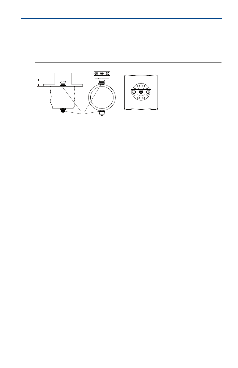
2. Place four 1/4-in. (6-mm) tack welds at 90° increments. Check alignment of the
mounting both parallel and perpendicular to the axis of flow (see Figure 6). If
alignment of the mounting is within tolerances, finish weld per local codes. If
alignment is outside of specified tolerance, make adjustments prior to making
the finish weld.
Figure 6. Alignment
A. Tack welds
B. ODF
3. Center the fitting for the opposite side support over the opposite side hole,
gap 1/16-in. (1,6 mm), and place four 1/4-in. (6 mm) tack welds at 90°
increments. Insert the sensor into the mounting hardware. Verify that the tip
of the sensor is centered in the opposite side fitting and the plug will fit around
sensor. Finish weld per local codes. If alignment of the bar does not allow
enough clearance to insert the opposite side plug, make adjustments prior to
making the finish weld.
4. To avoid serious burns, allow the mounting hardware to cool before
continuing.
5.0 Insert the Rosemount Annubar Sensor
1. Align the flow arrow on the head with the direction of flow. Assemble the bar to
the mounting flange using a gasket, bolts, and nuts.
2. Tighten the nuts in a cross pattern to allow even compression of the gasket.
3. If opposite side support is threaded, apply an appropriate thread sealing
compound to the support plug threads and tighten.
4. If opposite side support is a socket-weld fitting, insert the plug into it fitting
until the parts contact. Retract the plug
Rosemount Annubar Sensor, and apply fillet weld per local codes.
1
/16-in. (1,6 mm), remove the
11
Page 12

Quick Start Guide
June 2016
6.0 Mount the transmitter
6.1 Transmitter mounting, direct mount head with valves
It is not necessary to retract the Annubar when direct mounting a transmitter
with valves.
1. Place O-rings into grooves on the face of head.
2. Align the high side of the transmitter to the high side of the sensor (“Hi” is
stamped on the side of the head) and install.
3. Tighten the nuts in a cross pattern to 384 in-lb (43 N-m).
6.2 Transmitter mounting, direct mount head without valves
1. Place O-rings into grooves on the face of head.
2. Orient the equalizer valve(s) so they are easily accessible. Install a manifold
with the smooth face mating to the face of the head. Tighten in cross pattern
to a torque of 384 in-lb (43 N-m).
3. Place O-rings into grooves on the face of the manifold.
4. Align the high side of the transmitter to the high side of the sensor (“Hi” is
stamped on the side of the head) and install.
5. Tighten the nuts in a cross pattern to 384 in-lb (43 N-m).
6.3 Transmitter mounting with remote mount head
Temperatures in excess of 250 °F (121 °C) at the electronics will damage the
transmitter. Remote mounted electronics are connected to the sensor by means
of impulse piping, which allows service flow temperatures to decrease to a point
where the transmitter is no longer vulnerable.
Different impulse piping arrangements are used depending on the process fluid
and must be rated for continuous operation at the pipeline design pressure and
temperature. A minimum of
with a wall thickness of at least 0.035-in. (0,9 mm) is recommended including and
under 600# ANSI (DN 50 PN100). Above 600# ANSI (DN 50 PN100), use
(1,6 mm) stainless steel tubing. Threaded pipe fittings are not recommended
because they create voids where air can become entrapped and create leakage
points.
The following restrictions and recommendations apply to impulse piping
location:
1. Impulse piping that runs horizontally must slope at least one inch per foot
(83 mm/m).
- Slope downward (toward the transmitter) for liquid and steam applications
- Slope upward (toward the transmitter) for gas applications.
2. For applications with temperature below 250 °F (121 °C), impulse piping
should be as short as possible to minimize temperature changes. Insulation
may be required.
1
/2-in. (12 mm) outer diameter stainless steel tubing
1
/16-in.
12
Page 13
June 2016
To PL
ME
To PH
MH
DVH
ML
DVL
2
1
Quick Start Guide
3. For applications above 250 °F (121 °C), impulse piping should have a minimum
length of 1 ft. (0,3048 m) for every 100 °F (38 °C) temperature increase over
250 °F (121 °C). Impulse piping must be non-insulated to reduce fluid
temperature. Any threaded connections should be checked after the system
reaches the intended temperature because connections may come loose with
contraction and expansion caused by temperature change.
4. Outdoor installations for liquid, saturated gas, or steam may require insulation
and heat tracing to prevent freezing.
5. When impulse piping is longer than 6 ft. (1,8 m) the high and low impulse
lines must be positioned together to maintain equal temperature. They must
be supported to prevent sagging and vibration.
6. Impulse lines should be positioned in protected areas or against walls or
ceilings. Use appropriate pipe sealing compound rated for the service
temperature on all threaded connections. Do not place the impulse piping
near high temperature piping or equipment.
An instrument manifold is recommended for all installations. Manifolds allow an
operator to equalize the pressures prior to zeroing and isolates the process fluid
from the transmitter.
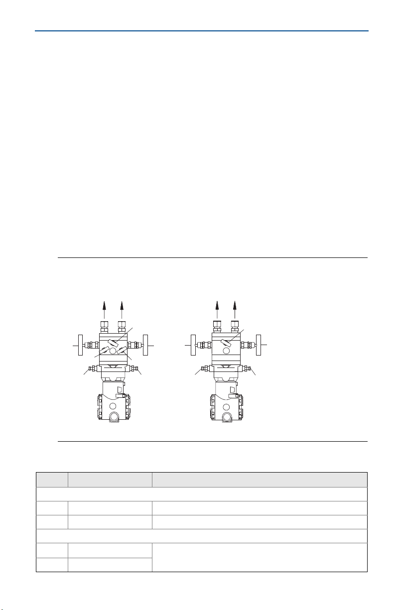
Figure 7. Valve Identification for 5-Valve and 3-Valve Manifolds
5-valve manifold 3-valve manifold
To PH To PL
MV
MH
2
MEH
DVH
1
ML
MEL
DVL
Table 4. Description of Impulse Valves and Components
Name Description Purpose
Component s
1 Tra ns m it te r Reads Differential Pressure
2 Manifold Isolates and equalizes transmitter
Manifold and impulse valves
PH
PL Primary sensor
Primary sensor
(1)
(2)
High and low side pressure process connections.
13
Page 14
Quick Start Guide
Name Description Purpose
DVH Drain/vent valve
DVL Drain/vent valve
MH Manifold
ML Manifold
MEH Manifold equalizer
MEL Manifold equalizer
ME Manifold equalizer Allows high and low side pressure to equalize
MV Manifold vent valve Vents process fluid
1. High pressure
2. Low pressure
(1)
(2)
(1)
(2)
(1)
(2)
Drains (for gas service) or vents (for liquid or steam service) the DP
transmitter chambers
Isolates high side or low side pressure from the process
Allows high and low pressure side access to the vent valve, or for
isolating the process fluid
6.4 Recommended installations
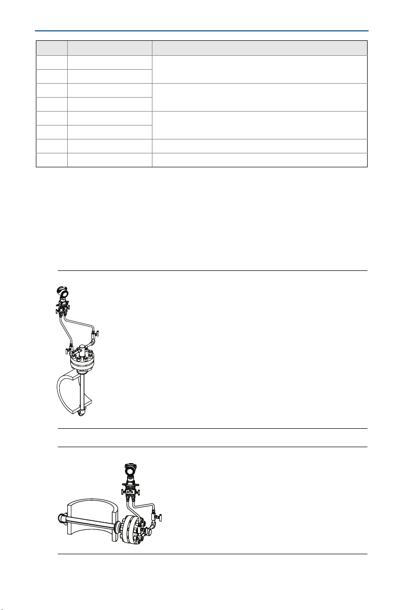
Gas service
Secure the transmitter above the sensor to prevent condensable liquids from
collecting in the impulse piping and the DP cell.
Figure 8. Horizontal Gas
June 2016
Figure 9. Vertical Gas
14
Page 15
June 2016
Quick Start Guide
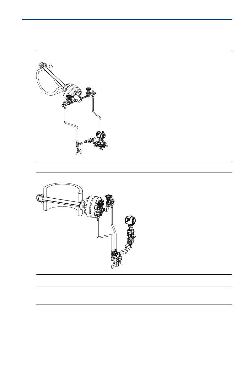
Steam and liquid service
Mount the transmitter below the process piping. Route the impulse piping down
to the transmitter and fill the system with cool water through the two tee fittings.
Figure 10. Horizontal Steam and Liquid
Figure 11. Vertical Steam and Liquid
Note
Ensure the drain legs are long enough to capture the dirt particles and sediment.
15
Page 16
Quick Start Guide
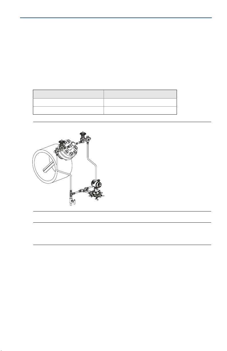
Steam on top service
For remote mount installations the impulse piping should slope up slightly from
the instrument connections on the Rosemount 585 to the cross fittings allowing
condensate to drain back into the pipe. From the cross fittings, the impulse
piping should be routed downward to the transmitter and the drain legs. The
transmitter should be located below the instrument connections of the
Rosemount 585. Depending on the environmental conditions, it may be
necessary to insulate the mounting hardware.
Table 5. Steam on Top Temperature Limits
Transmitter connection platform Maximum temperature
Remote mount 850 °F (455 °C)
Direct mount 400 °F (205 °C)
Figure 12. Horizontal Steam on Top
June 2016
Note
Top mounting for steam applications is an appropriate mounting option in many cases.
Consult Rosemount Customer Central for instructions regarding steam on top mounting.
16
Page 17

June 2016
Quick Start Guide
7.0 Product certifications
7.1 Approved Manufacturing Locations
Emerson Process Management – Shakopee, Minnesota USA
Rosemount DP Flow Design and Operations – Boulder, Colorado USA
Emerson Process Management GmbH & Co. OHG – Wessling, Germany
Emerson Process Management Asia Pacific Private Limited – Singapore
Emerson Beijing Instrument Co., Ltd – Beijing, China
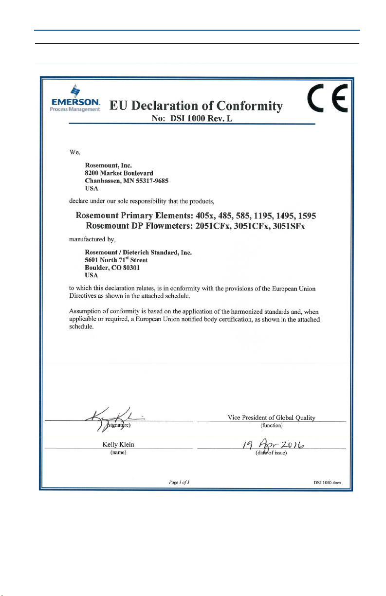
7.2 European Directive Information
The EC declaration of conformity for all applicable European directives for this
product can be found on the Rosemount website at
EmersonProcess.com/Rosemount
our local sales office.
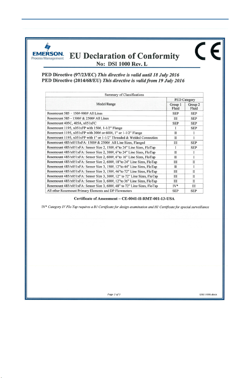
European Pressure Equipment Directive (PED) (97/23/EC)
Rosemount 585 Annubar — Refer to EC declaration of conformity for conformity
assessment
Pressure Transmitter — See appropriate Pressure Transmitter QSG
7.3 Hazardous Locations Certifications
For information regarding the transmitter product certification, see the
appropriate transmitter QSG:
Rosemount 3051S Series Pressure Transmitter and Rosemount 3051SF Series
Flowmeter Quick Start Guide.
Rosemount 3051S MultiVariable Transmitter and Rosemount 3051SF Series
Flowmeter MultiVariable Transmitter Quick Start Guide
Rosemount 3051 Pressure Transmitter and Rosemount 3051CF Series
Flowmeter Transmitter Quick Start Guide.
Rosemount 2051 Pressure Transmitter and Rosemount 2051CF Series
Flowmeter Transmitter Quick Start Guide.
. A hard copy may be obtained by contacting
.
17
Page 18
Quick Start Guide
Figure 13. Rosemount 585 Declaration of Conformity
June 2016
18
Page 19
June 2016
Quick Start Guide
19
Page 20

Quick Start Guide
June 2016
20
Page 21
June 2016
表表格
1B: 含有China RoHS
管控物峐超彯㚨⣏㳻⹎旸ῤ的部件型号列表
Rosemount 585
Table 1B: List of Rosemount 585 Parts with China RoHS Concentration above MCVs
部件名称
Part Name
有害物峐ġİġHazardous Substances
摭
Lead
(Pb)
汞
Mercury
(Hg)
擱
Cadmium
(Cd)
六价撔
Hexavalent
Chromium
(Cr +6)
多ⓤ俼劗
Polybrominated
biphenyls
(PBB)
多ⓤ俼劗慂
Polybrominated
diphenyl ethers
多ⓤ俼劗慂
(PBDE)
䬍ࡦᓖՐ
ᝏಘཆ༣㓴
Ԧ
Aluminum
RTD
Housing
Assembly
O O O X O O
本表格系依据
SJ/T11364
的奬⭂侴⇞ἄįġ
This table is proposed in accordance with the provision of SJ/T11364
O:
意宍悐ẞ䘬㚱⛯峐㛸㕁宍㚱⭛䈑峐䘬⏓慷⛯ỶḶ
GB/T 26572
所奬⭂䘬旸慷天㯪įġ
O: Indicate that said hazardous substance in all of the homogeneous materials for this part is below the limit requirement of
GB/T 26572.
X:
意⛐宍悐ẞἧ䓐䘬㚱⛯峐㛸㕁慴炻军⮹㚱ᶨ䰣⛯峐㛸㕁宍㚱⭛䈑峐䘬⏓慷檀Ḷ
GB/T 26572
所奬⭂䘬旸慷天㯪įġ
X: Indicate that said hazardous substance contained in at least one of the homogeneous materials used for this part is above
the limit requirement of GB/T 26572.
к䘠⭣᰾ӵ䘲⭘Ҿ䘹ᤙ䬍ࡦཆ༣㓴ԦⲴӗ૱DŽަԆᡰᴹᐞ⍱䟿а⅑ݳԦⲴ㓴ԦᡰᴹⲴ China RoHS ㇑᧗⢙䍘⎃
ᓖ൷վҾ GB/T 26572 ᡰ㿴ᇊⲴ䲀䟿㾱≲DŽޣҾᐞ⍱䟿䇑䘱ಘ㓴ԦⲴ㇑᧗⢙䍘⎃ᓖⲴ⭣᰾ˈ䈧৲ⴻ䘱ಘⲴᘛ
䙏ᆹ㻵ᤷইDŽ
The disclosure above applies to units supplied with aluminum connection heads. No other components supplied
with DP Flow primary elements contain any restricted substances. Please consult the transmitter Quick Start
Guide (QIG) for disclosure information on transmitter components.
Quick Start Guide
21
Page 22

Global Headquarters
Emerson Process Management
6021 Innovation Blvd.
Shakopee, MN 55379, USA
+1 800 999 9307 or +1 952 906 8888
+1 952 949 7001
[email protected]
North America Regional Office
Emerson Process Management
8200 Market Blvd.
Chanhassen, MN 55317, USA
+1 800 999 9307 or +1 952 906 8888
+1 952 949 7001
[email protected]
Latin America Regional Office
Emerson Process Management
1300 Concord Terrace, Suite 400
Sunrise, FL 33323, USA
+1 954 846 5030
+1 954 846 5121
[email protected]
Europe Regional Office
Emerson Process Management Europe GmbH
Neuhofstrasse 19a P.O. Box 1046
CH 6340 Baar
Switzerland
+41 (0) 41 768 6111
+41 (0) 41 768 6300
[email protected]
Asia Pacific Regional Office
Emerson Process Management Asia Pacific Pte Ltd
1 Pandan Crescent
Singapore 128461
+65 6777 8211
+65 6777 0947
[email protected]
Middle East and Africa Regional Office
Emerson Process Management
Emerson FZE P.O. Box 17033,
Jebel Ali Free Zone - South 2
Dubai, United Arab Emi rates
+971 4 8118100
+971 4 8865465
*00825-0100-4585*
Quick Start Guide
00825-0100-4585, Rev AB
Linkedin.com/company/Emerson-Process-Management
Twitter.com/Rosemount_News
Facebook.com/Rosemount
Youtube.com/us er/RosemountMeasur ement
Google.com/+RosemountMeasurement
Standard Terms and Conditions of Sale can be found at
www.Emerson.com/en-us/pages/Terms-of-Use.aspx
The Emerson logo is a trademark and service mark of Emerson
Electric Co.
Annubar, Rosemount, and Rosemount logotype are trademarks of
Emerson Process Management.
All other marks are the property of their respective owners.
© 2016 Emerson Process Management. All rights reserved.
June 2016
 Loading...